Article

Vision-Assisted Interactive Human-in-the-Loop Distal Upper Limb Rehabilitation Robot and its Clinical Usability Test

1
Department of Biomedical Engineering, Seoul National University College of Medicine, Seoul 03080, Korea
2
Department of Rehabilitation Medicine, Seoul National University Hospital, Seoul 03080, Korea
3
Interdisciplinary Program for Bioengineering, Seoul National University Graduate School, Seoul 08826, Korea
4
Korea Electrotechnology Research Institute, Ansan 15588, Korea
5
Institute of Medical and Biological Engineering, Seoul National University, Seoul 03080, Korea
*
Authors to whom correspondence should be addressed.
Appl. Sci. 2019, 9(15), 3106; https://doi.org/10.3390/app9153106
Submission received: 24 June 2019 / Revised: 17 July 2019 / Accepted: 29 July 2019 / Published: 1 August 2019

Abstract

:

Featured Application

The main contribution of this study is the development of a novel concept of a rehabilitation robot for stroke, helping to close the neuro-feedback loop. To facilitate neuroplasticity, a vision-assisted control algorithm was implemented to meet user-intent.

Abstract

In the context of stroke rehabilitation, simple structures and user-intent driven actuation are relevant features to facilitate neuroplasticity as well as deliver a sufficient number of repetitions during a single therapy session. A novel robotic treatment device for distal upper limb rehabilitation in stroke patients was developed, and a usability test was performed to assess its clinical feasibility. The rehabilitation robot was designed as a two-axis exoskeleton actuated by electric motors, consisting of forearm supination/pronation and hand grasp/release, which were selected based on a kinematic analysis of essential daily activities. A vision-assisted algorithm was utilized for user-intent extraction in a human-in-the-loop concept. A usability test was performed on six physiatrists, five biomedical engineers, five rehabilitation therapists, two chronic stroke patients, and two caregivers of the patients. After sufficient instruction, all subjects tested the robot for a minimum of 10 min and completed the evaluation form using a 7-point Likert scale. The participants found the device interesting (5.7 ± 1.2), motivating (5.8 ± 0.9), and as having less possibility of causing injury or safety issues (6.1 ± 1.1); however, the appropriateness of difficulty (4.8 ± 1.9) and comfort level (4.9 ± 1.3) were found to be relatively low. Further development of the current device would provide a good treatment option as a simple, low-cost, and clinically feasible rehabilitation robot for stroke.

1. Introduction

The high incidence of stroke [1] and the recent trend toward developing rehabilitation robots have led to the development of several types of rehabilitation robots [2]. Over the past few years, there have been considerable improvements in neurorehabilitation robotics. However, not many types of neurorehabilitation robots have entered the developmental stage for large-scale randomized controlled clinical trials, nor have they been widely commercialized. Part of the reason for this would be the regulation issues pertaining to medical devices; however, a more important factor could be a lack of sustainable motivation to practically achieve sufficient “task-specific high repetition” throughout the long-term rehabilitation process [3,4,5]. From a clinical perspective, it is undeniable that more task-specific repetition of the paralyzed extremity would lead to better recovery in patients with limb paralysis caused by central nervous system (CNS) injuries or disorders. In fact, most of the rehabilitation robots focus on providing high repetitions and maintain motivation by applying virtual reality or gamification factors, such as providing disturbance during desired movements [6,7,8,9,10]. Robots that are developed as assistive devices, which interact with real objects, would primarily provide ultimate task-specific movements [11,12,13,14].
In general, electromechanical devices and robots for upper limb rehabilitation are classified into three major categories: Grounded end-effector robots, grounded exoskeletons, and wearable exoskeletons [8,15]. Grounded end-effector type robots are relatively simple in structure. These robots usually let the patients hold a handle with their hands and the handle generates power according to its trajectory and direction. The joint of the robot does not correspond with human anatomical structure; therefore, there are various types of end-effector robots [16]. InMotion is the most representative type of the end-effector type robot [17]. End-effector robots are generally not in a wearable form; therefore, they are mostly fixed or grounded in one space and are mainly used in the clinics. Grounded exoskeletons have a structure in which the robot joints correspond to human joints [16]. These types of robot are generally large and expensive, and they are usually fixed in space, which makes them only usable in occupational therapy rooms in hospitals. Armeo series exoskeleton robots are the most representative exoskeletons [18]. Wearable exoskeletons are similar to grounded exoskeletons in structural concept, however, they require a light-weight to be portable. This type usually falls into the assistive device category and include a robotic interface, mostly in hand exoskeleton form, for interaction with real objects. Examples of this type are Gloreha and Hand of hope [13,19]. Another type of upper limb rehabilitation robot could be arm support devices [10,20,21]. While it is not clear whether either type of rehabilitation robot is better than another, numerous systematic reviews and meta-analyses showed conflicting results on the efficacy of robot-assisted arm rehabilitation [2,15]. There is growing evidence that robot-assisted training improves both muscle strength and functional abilities, however, whether the amount of increase in outcome measures is clinically significant remains questionable, especially when considering cost-effectiveness.
Regardless of the robot type, the most important reason that the efficacy of robot-assisted training is currently not as high as expected [2] seems to be that it simply does not provide a sufficient amount of task-specific repetition [22]. Many factors contribute to this limitation, including the patient’s medical status, functional status, socioeconomic factors, hospital accessibility, insurance policies, etc. Because all these factors are not easily controllable in many aspects, it is necessary to develop a rehabilitation robot that is affordable, clinically feasible, and portable, which will make the robot more accessible, and eventually maximize the task-specific repetition of the paralyzed limb.
For the robots to be applicable in daily activities, they need to be portable, simple, controllable according to the user’s intent, and be able to involve real target objects instead of providing a monitor screen or virtual reality. Most of the robots use force sensors, torque sensors, or surface electromyography to recognize the user’s intent [23]. However, it is difficult for people with severe limb impairment to generate sufficient input signals for such sensors. Recently, active research on brain-machine interface (BMI) is being conducted to extract user-intent directly from the brain signals. However, it is very challenging to perform precise control of the robot with electroencephalography signals, which is the most commonly used non-invasive brain signal, because the signal-to-noise ratio is very low. Furthermore, BMI technology involving invasive brain signals, such as intracortical signals or electrocorticography (ECoG), is far from practical utilization [24,25,26]. To maximize neuroplasticity in using rehabilitation robots, the robot should move according to the user’s intent, or at least the patient should be able to anticipate the robot’s movement. Electromyography (EMG) and torque sensor-based controls are not applicable to patients with flaccid paralysis or with only minimal volitional movements.
In this study, we attempted to apply an image processing-based approach that can reflect user-intent. Visual compensation using camera images in the BMI control of the robotic arm has recently been introduced [27]. Bang et al. [28] suggested an upper limb rehabilitation robot system for precision control by camera-based image processing. We hypothesized that visual compensation using a camera image-processing algorithm could assist the exoskeleton robot to be actuated according to the user-intent, and therefore complete the eye–brain–limb–object neural feedback loop, which may facilitate neuroplasticity. The purpose of this study was to develop a two-axis rehabilitation robot for the distal upper limb, which is controlled by the user-intent through vision assistance in a human-in-the-loop concept (Figure 1). The basic concept was to mount a camera on the exoskeleton, and when the user targets an object to grasp and confirm with a hardware control panel, the user would move the robot to the target using proximal upper limb residual power (human contribution). The orientation of the robot would be adjusted automatically according to the shape and usage of the target image acquired by the camera (robot contribution), and the robot would eventually grasp the object following user confirmation. We also aimed to investigate its clinical feasibility through a pilot usability test.
In the next sections, the design and assembly of the new concept rehabilitation robot is presented, followed by a preliminary usability test performed on developers, clinicians, and patients.

2. Materials and Methods

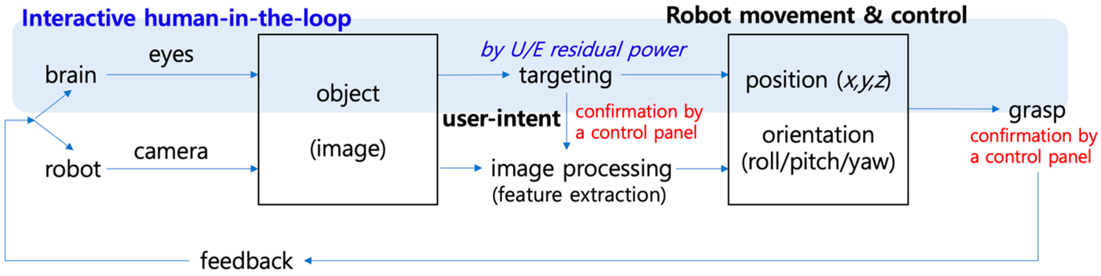
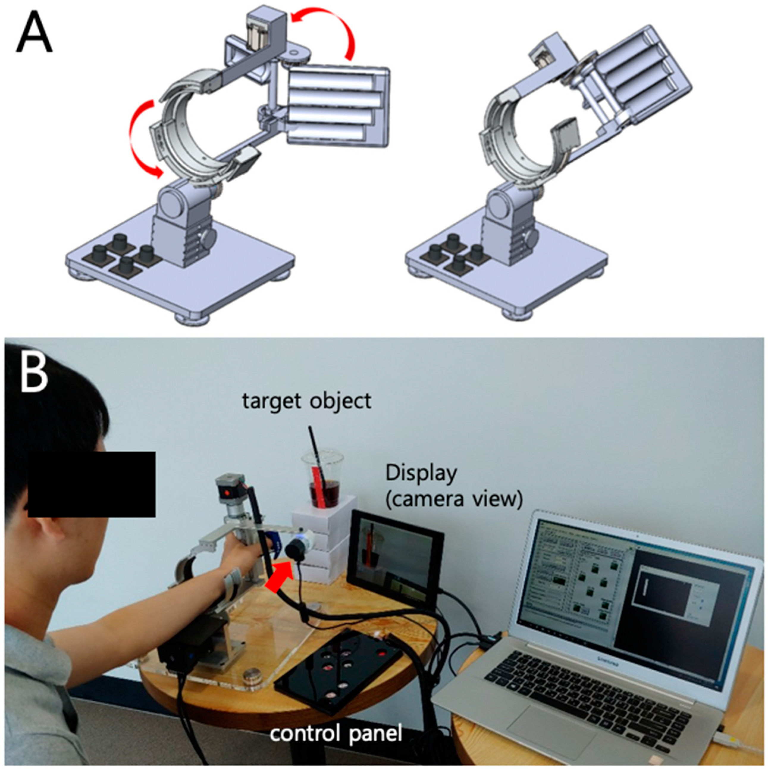
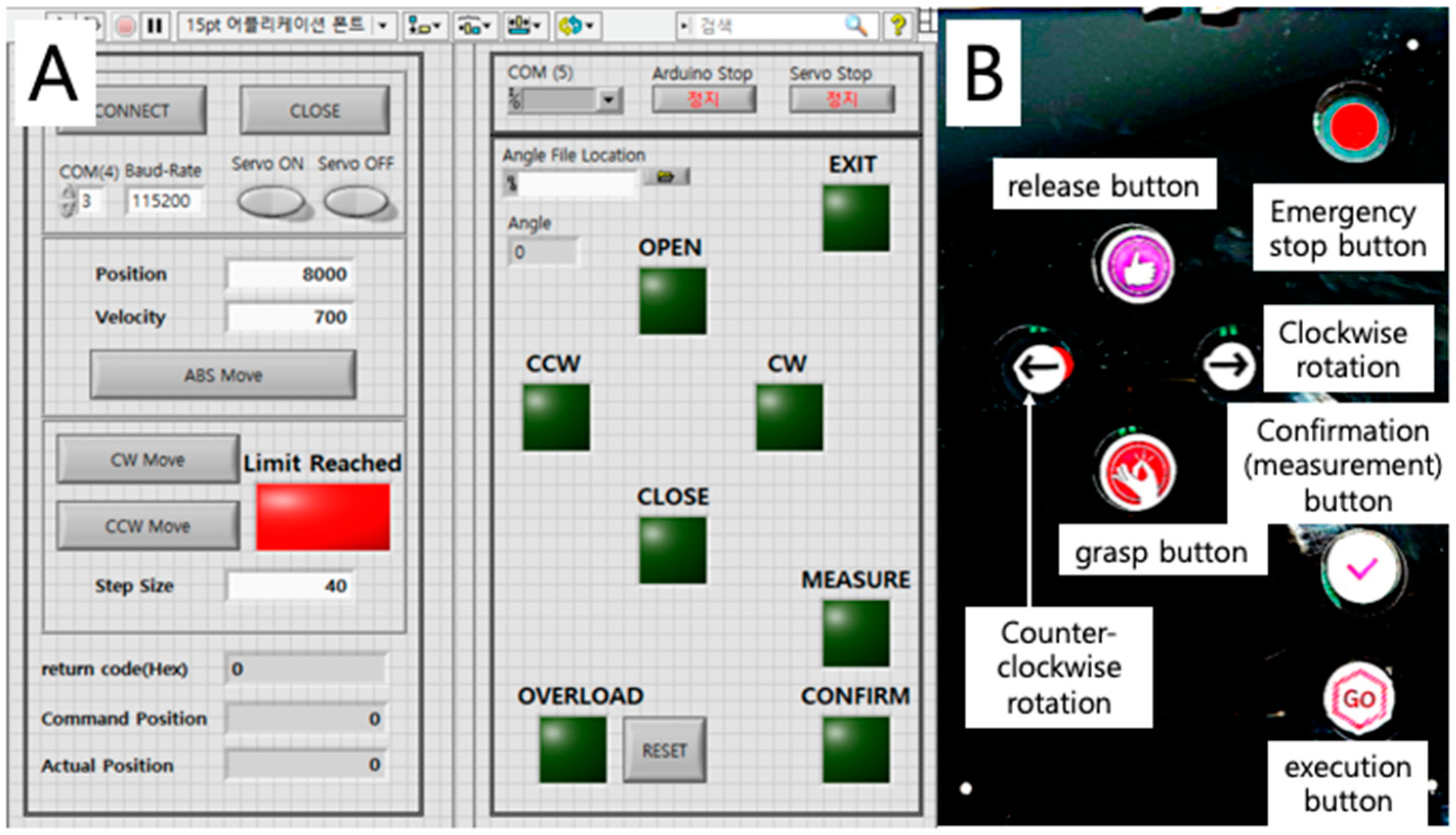
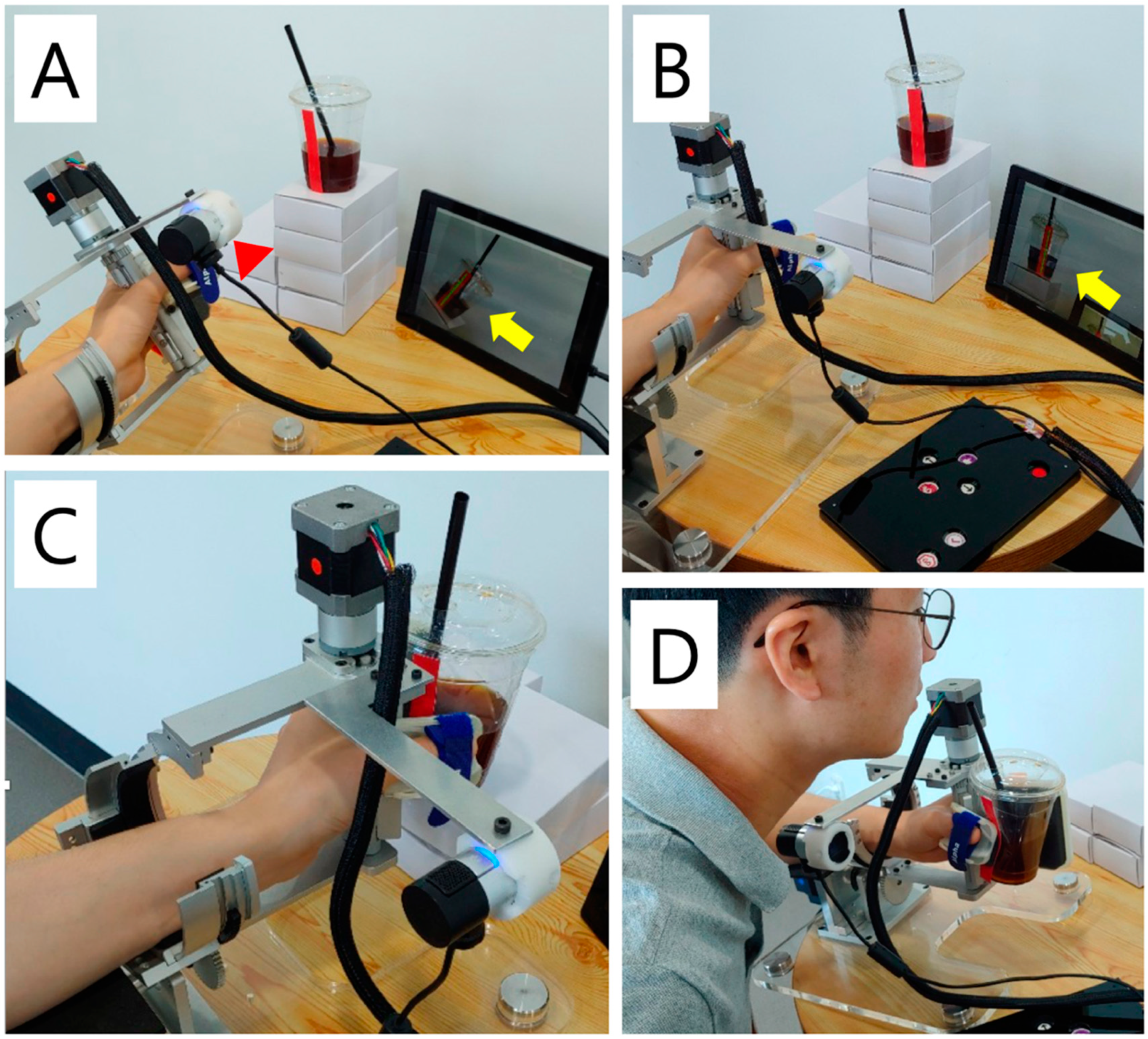
2.1. Development of a Vision-Assisted Distal Upper Limb Rehabilitation Robot

2.1.1. Design of a Two-Axis Distal Upper Limb Rehabilitation Robot

We selected forearm supination/pronation as the essential joint motion in recovery from stroke, based on our previous studies using kinematic analysis for important activities of daily living [29]. For the execution of the task, a hand grasp/release motion was included in the design. Based on the fact that most stroke patients experience proximal limb recovery in the early stage, we assumed that most of the potential users for this device would have a certain extent of shoulder power and movement. The forearm support structure was manufactured in the form of a skateboard with four small wheels mounted at the bottom, so that the user could roll the whole device freely in any direction with their residual and/or recovered shoulder movement. Contrary to our initial design (Figure 2A), in this pilot study, the height adjustment function was excluded for simplicity. This design structure was intended to make the device feasible to use at the hospital bedside or at home. The whole system used in this study is shown in Figure 2B.
In the current design, the exoskeleton body part for the hand was placed at the volar side of the hand, while most of the hand robots’ exoskeleton body are placed at the dorsum side [12,13,19,30,31]. This was to prevent hand injury that may be caused by the excessive grasp motion of the robot. In addition, this prototype was designed for patients with left hemiplegia considering a planned usability test, which requires less language deficit to learn and understand how to control the robot and also provides usability related feedback. It is known that the language function is lateralized in the left hemisphere of the brain [32], so patients with a right hemispheric lesion (left hemiplegia) would be more appropriate for the usability test study.

2.1.2. Assembly of the Robot

The distal upper limb rehabilitation robot proposed and developed in this study consists of two parts, forearm and hand regions, each containing a motor. The first part is the forearm region, providing supination and pronation motion through the servo motor (Ezi-Servo Series, Fastech, Bucheon, Korea) placed at the back of the robot. The motor movement is translated to forearm supination/pronation motion through the use of gears. A small circular gear is placed at the tip of the motor and a larger circular gear containing the hand region is matched with the small gear. The motor movement is controlled using LabVIEW® program (LabVIEW® 2013, National Instruments, Austin, TX, USA) and can be manipulated automatically and manually through the use of buttons on the control panel. The motion was limited to a certain range (approximately ± 30°) for safety.
The second part of the rehabilitation robot enables grasp motion of the hand. Similar to the forearm region, the hand region produces gripping motion from a stepping motor (PGM32-NK243, Robot Mart, Gimpo, Korea) by the use of a geared mechanism, where one part of the gripping plate connected to the motor’s shaft is matched with the other for opening and closing motions. This motor is controlled by the buttons on the control panel and the information from the buttons is collected and transferred via Arduino (Arduino UNO, Arduino, Italy).
The control panel for the rehabilitation robot consists of seven pressure sensors (400 FSR, Interlink Electronics, Inc., Camarillo, CA, USA) and the data from them are processed via Arduino. The buttons on the control panel consist of forearm supination/pronation motion, closing/opening of grasp motion, emergency stop, confirmation (measurement) button for image processing, and execution button for automatic movement according to the result of image processing (Figure 3).
The LabVIEW control program collects data from the control panel via Arduino, visualizes the image from the camera, and controls the forearm supination/pronation motion both manually and automatically. The camera (LifeCam StudioTM, Microsoft®, Redmond, WA, USA) is mounted on the bar connected to the grasping axis of the robot in parallel, so that the robot hand axis and the camera axis is the same. The camera image is displayed on a separate LCD display panel (Camel Co., Ltd., Seoul, Korea).

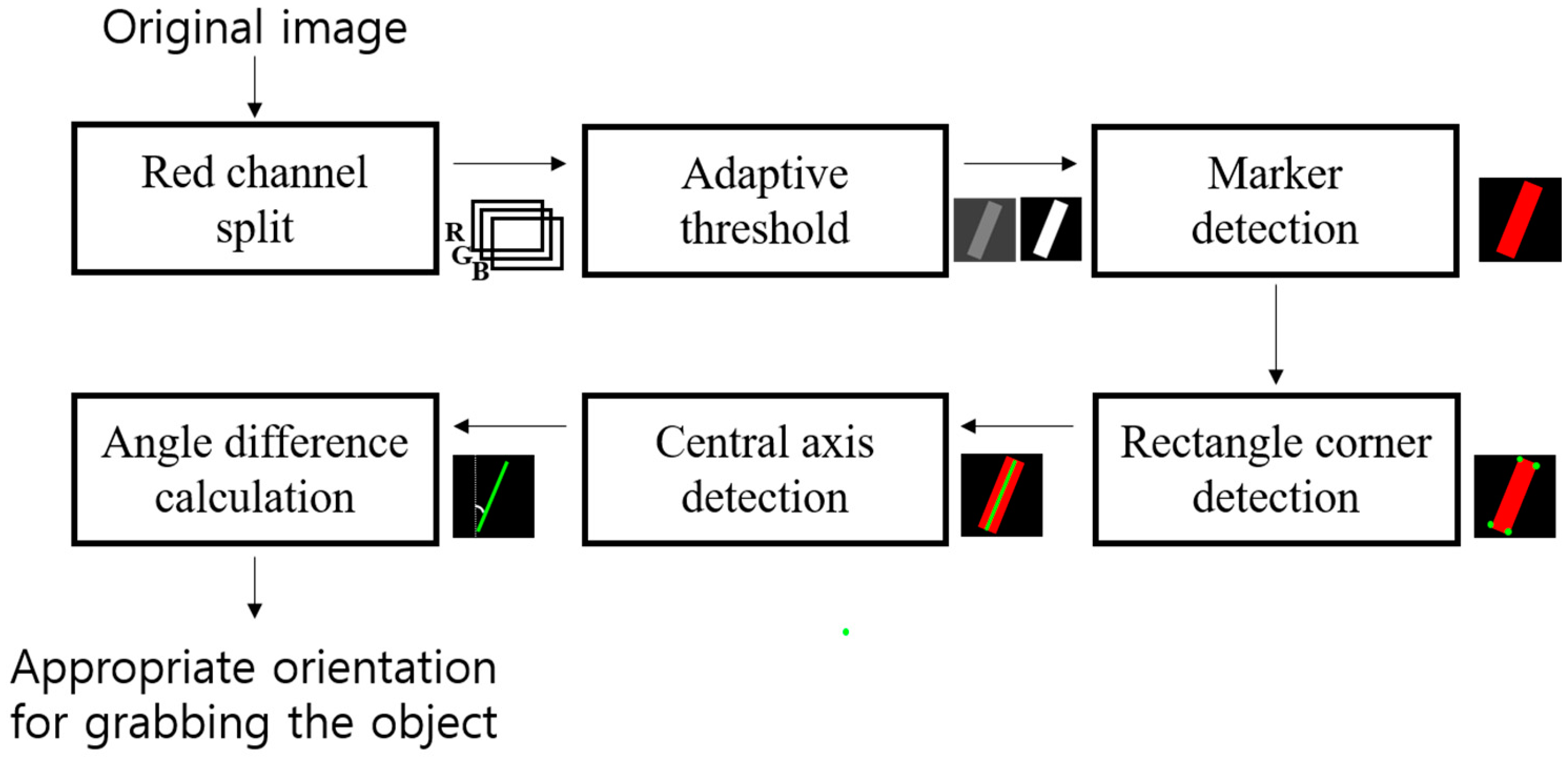
2.1.3. Image-Processing Algorithm for Recognizing User-intent

In this distal upper limb rehabilitation robot, the camera is mounted on the exoskeleton. This is different from other types of image-guided robot control devices, in which most of the cameras in other robots are placed externally in a fixed coordinate system [27,33]. This concept comes from a snake-eye view [34], in contrast to the human-eye view. A similar concept has been proposed in laboratories for navigation and exploration [35]. In this robot, the “image-guided” concept refers to targeting the object and deriving the appropriate orientation for grabbing the object.
When the user wearing the robot attempts to grasp a target object, the user moves the robot in the direction of the target object so that the mounted camera aims the object and the image from the camera is shown on the LCD display. This stage is done by the user themselves, using the residual proximal muscle power of the impaired limb and the wheels on the bottom of the plate. When the object is shown near the center of the display, the camera detects the long axis of the object. In the current preliminary study, we used a red rectangular marker to track the object and calculate the desired rotation angle. To clearly detect the red color, image processing was applied to the red channel. As shown in Figure 4, the coordinates of the four corners are obtained from the marker detected in the red channel, and the center axis of the rectangle is calculated. An image-processing algorithm was implemented to the system using Visual Studio 2017 (Microsoft®, Redmond, WA, USA), C# and Opencvsharp 2.4.5. After image processing, the display shows the detected long-axis on the screen waiting for the user’s confirmation. Then, the confirmation (measurement) button is pressed by the user and the software calculates the difference between the grasp axis and the long axis of the object. Then, the supination/pronation axis of the robot automatically rotates to provide an appropriate orientation to grab the object upon pressing the execution button. The rotation speed is set to a moderate speed in order to prevent any possible musculoskeletal injuries. Although the ultimate goal of the development would not need confirmation and execution buttons as the recognition software will automatically analyze the object, these buttons were added to prevent recognition errors, which may induce malfunction and patient injury.
Once the robot is oriented in the right position, the user confirms the position with the grasp button and the robot hand grabs the object. Figure 5 shows the basic concept and process of the robot.

2.2. Preliminary Usability Test

2.2.1. Participants

A total of 20 subjects participated in the usability test for the developed robot. They consisted of six rehabilitation doctors (6 men), five robot engineers (2 men; 3 women), rehabilitation therapists (5 women: 1 physical therapist, 4 occupational therapists), two chronic stroke patients with left hemiplegia (2 men, 59-year old and 72-year old), and their long-term caregivers (2 women). All participants had sufficient experience regarding rehabilitation robots in their point-of-view, and they were instructed to evaluate the device in their perspectives of professional experience. The caregivers in this study had taken care of the stroke patients for several years and had experience with various rehabilitation robots in many different hospitals. Therefore, they were categorized as ‘patients’ in the point-of-view that they would know patient demands well, distinct from subjects in other categories. This study was approved by the Institutional Review Board (IRB) of Seoul National University Hospital (IRB No. 1610-043-797).

2.2.2. Procedure

All participants wore the robot with their left limb. Following 10 min of demonstration and instruction, they were told to use the robot freely for 10 min, including the bottle grasping task. Then, they were asked to fill out the survey form. The survey consisted of 10 items in a seven-point Likert scale [36], asking for the respondent’s overall satisfaction, interest, motivation, expected improvement in recovery, difficulty, discomfort, safety, comparison to other therapeutic robots, willingness to use, and expected efficacy after commercialization. For the rating instructions, 7 points represented most satisfactory or safe, and 0 points represented least satisfactory or unsafe. Opinions on limitations and points to improve the robot were also obtained.

2.2.3. Statistical Analysis
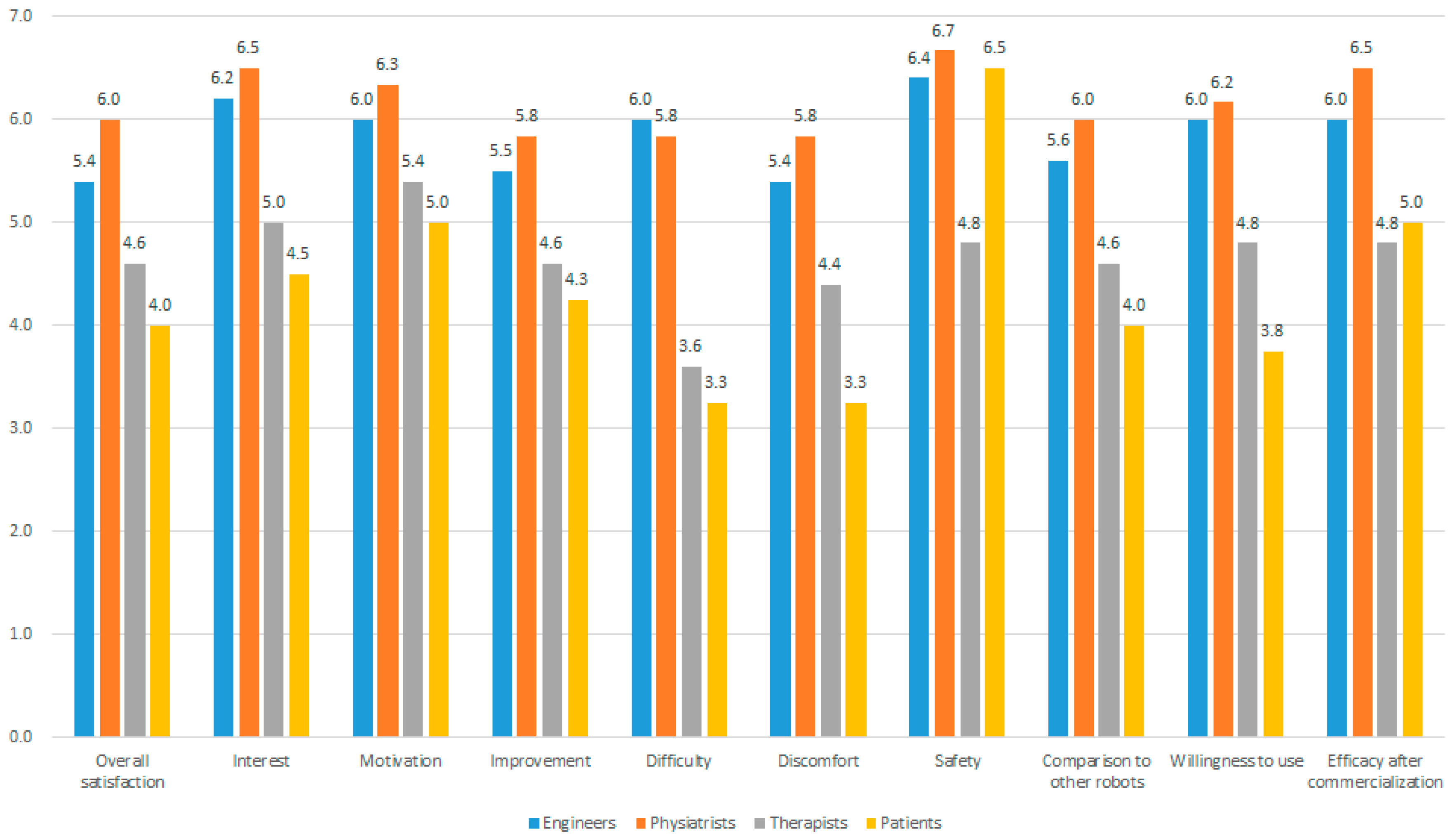
Descriptive statistical analyses (mean, standard deviation) were performed for each survey item in each respondent group and also for total subjects. Kruskal–Wallis tests were performed for each item followed by Mann–Whitney tests as a post-hoc analysis for comparison between each group. All statistical analyses in this study were performed using SPSS v21.0 (SPSS Inc., Chicago, IL, USA).

3. Results

For overall satisfaction regarding the robot’s ability to help stroke rehabilitation, physiatrists rated with the highest score (6.0 ± 0.9), followed by robot engineers (5.4 ± 0.5), therapists (4.6 ± 0.5), and patients (4.0 ± 1.2). Among the survey items with high scores were interest (5.7 ± 1.2), motivation (5.8 ± 0.9), and having less possibility of injury or safety issues (6.1 ± 1.1). Ratings on enhancing motivation did not show a significant difference between the subgroups by the Kruskal–Wallis test (p = 0.094). However, the level of difficulty (4.8 ± 1.9), expectance of improvement (5.1 ± 1.0), and comfort (4.9 ± 1.3) were rated relatively low. Patients significantly responded with low scores for difficulty and comfort compared to physicians (p = 0.038 and 0.010, respectively) and therapists (p = 0.032 and 0.032, respectively). Results from the Mann–Whitney test demonstrated that physicians and engineers did not show significant differences for all survey items (p > 0.05), and therapists and patients also did not show significant differences for all items (p > 0.05). Detailed response results are shown in Figure 6.
A number of issues were raised during the usability test. Major issues included a need for sensory feedback at the end of the range of motion while grasping, height adjustment function, and modification of the control method to support an active assistive range of motion exercise. The issues raised and possible solutions are shown in Table 1.

4. Discussion

The main concept of the developed rehabilitation robot is to close the loop to provide continuous feedback to enhance neuroplasticity in stroke recovery. Zrenner et al. [37] proposed two conceptual loops in brain modulation. One is “brain-state dynamics” loop and another is the “task dynamics” loop. The task dynamics loop involves motor-sensory feedback between the brain and the environment (object). In the design and development of the proposed robot, the main idea was to directly deliver visual information to the robot using the mounted camera instead of decoding occipital electroencephalography, while securing accurate visual information and actuating the robot according to the user-intent at the same time, therefore, closing the loop for the motor–visual–sensory feedback. It was also expected to promote patient motivation, which is an important factor for securing high repetition using the robot [38], because the rehabilitation robot system uses real objects instead of virtual interfaces, such as computer monitors or tablet displays.
In this research, we applied Tseng’s approach for a development and usability test of a new product [39]. The usability test results showed high scores for interest, motivation, and safety issues, but relatively low scores for difficulty, comfort, and expectance of improvement. Because this system did not use a computer display as the main interface, using real objects instead, which may be used at home or at the bedside, the respondents replied that these features were interesting and that the robot may help patients to be motivated for the therapy. The response from the patient group showed lower scores in most of the categories except safety. The patients responded that the device was not appropriate for their stroke recovery stage; however, they also commented that the device would be very useful for patients that are not able to move the distal upper limb.
The survey results showed that learning how to use the robot was difficult especially in responses by therapists and patients. A short training time may have affected this result. However, it is definite that the user interface and the control method should be improved in the next step of development for pertinent use in clinical studies or commercial use.
The main issues from the free comments were that the gripping was not highly secure, and that the task was limited due to the low degree of freedom. In the initial design, a height adjustment system was proposed so that the robot could grasp objects at various heights; however, for the current prototype, it was not applied due to the structural complexity. In the next version, the height adjustment system using a gravity compensation method is planned. Another feature of the current prototype was that the hand part was placed at the palm side of the hand, in contrast to other commercial hand exoskeletons, where it is place at the dorsum of the hand [7,30,31,40]. The reason for this design was to prevent injury since it is difficult to control gripping pressure. However, in this prototype, it was a problem in that it was not easy for the user to determine if the object was sufficiently grasped so that it would not fall down. The structure and position of the motors seemed to interfere with the user’s workspace, which should be modified in the next prototype. The use of pressure sensors should be considered in the next step as well [41].
In addition, a clinical proof-of-concept study should be performed, which was not available during this study due to IRB approval and Food and Drug Administration (FDA) clearance issues. It is necessary that the investigational device exemption (IDE) for medical robots with non-significant risk is practically applied in Korea to facilitate the development and proof-of-concept clinical studies for medical robots, so that clinically relevant robots may enter the market and be used in clinics as soon as possible, whereas clinically irrelevant robots may stop development at an earlier stage [42].
The proposed distal upper limb rehabilitation robot prototype had a number of limitations. The height adjustment system was not applied, resulting in a limited function of the robot. The contour of the hand part needs to be better customized to the real contour of the user’s hand to provide a better sense of grabbing objects. This may be solved by using three-dimensional printers.

5. Conclusions

In conclusion, a prototype of a simple, light-weight, distal upper limb exoskeleton rehabilitation robot, which recognizes user-intent by direction of the robot hand and camera image processing, was developed and its clinical usability and feasibility were supported from various aspects of professions and patients. Although the device requires further development for practical clinical application, providing high motivation and repetition with the proposed concept may assist in enhancing neuroplasticity in stroke recovery by helping to close the loop between the brain and the object.

Author Contributions

Conceptualization, H.S.N., H.G.S. and S.K.; Data curation, H.S.N.; Funding acquisition, H.S.N. and H.G.S.; Investigation, H.S.N., N.H., M.C., C.L. and S.K.; Methodology, M.C.; Resources, N.H., M.C. and S.K.; Software, N.H., M.C. and C.L.; Supervision, H.G.S.; Writing–original draft, H.S.N., N.H., M.C. and C.L.; Writing–review & editing, H.S.N., H.G.S. and S.K.

Funding

This work was supported by grant from The Health Fellowship Foundation, Seoul, Korea. The research was also supported by grant no. 04-2016-0870 from the Seoul National University Hospital Research Fund.

Declaration

Part of the authors (Nam H.S., Lee C., Seo H.G., Kim S.) has a Korean patent for the upper limb rehabilitation robot system for precision control by image processing registered to Seoul National University R & DB Foundation. This manuscript is a revision of part of the first author’s (Nam H.S.) Ph.D. thesis from Seoul National University. Otherwise, the authors declared no conflicts of interest with respect to the authorship and/or publication of this article.

Conflicts of Interest

The authors declare no conflict of interest.

References

  1. Carolei, A.; Sacco, S.; De Santis, F.; Marini, C. Epidemiology of stroke. Clin. Exp. Hypertens. 2002, 24, 479–483. [Google Scholar] [CrossRef] [PubMed]
  2. Mehrholz, J.; Pohl, M.; Platz, T.; Kugler, J.; Elsner, B. Electromechanical and robot-assisted arm training for improving activities of daily living, arm function, and arm muscle strength after stroke. Cochrane Database Syst. Rev. 2012, 6. [Google Scholar] [CrossRef]
  3. Huang, V.S.; Krakauer, J.W. Robotic neurorehabilitation: A computational motor learning perspective. J. Neuroeng. Rehabil. 2009, 6, 5. [Google Scholar] [CrossRef] [PubMed]
  4. Mazzoleni, S.; Duret, C.; Grosmaire, A.G.; Battini, E. Combining Upper Limb Robotic Rehabilitation with Other Therapeutic Approaches after Stroke: Current Status, Rationale, and Challenges. Biomed. Res. Int. 2017, 2017, 8905637. [Google Scholar] [CrossRef] [PubMed]
  5. Colombo, R.; Pisano, F.; Mazzone, A.; Delconte, C.; Micera, S.; Carrozza, M.C.; Dario, P.; Minuco, G. Design strategies to improve patient motivation during robot-aided rehabilitation. J. Neuroeng. Rehabil. 2007, 4, 3. [Google Scholar] [CrossRef]
  6. Novak, D.; Nagle, A.; Keller, U.; Riener, R. Increasing motivation in robot-aided arm rehabilitation with competitive and cooperative gameplay. J. Neuroeng. Rehabil. 2014, 11, 64. [Google Scholar] [CrossRef] [PubMed]
  7. Shin, J.H.; Kim, M.Y.; Lee, J.Y.; Jeon, Y.J.; Kim, S.; Lee, S.; Seo, B.; Choi, Y. Effects of virtual reality-based rehabilitation on distal upper extremity function and health-related quality of life: A single-blinded, randomized controlled trial. J. Neuroeng. Rehabil. 2016, 13, 17. [Google Scholar] [CrossRef]
  8. Gassert, R.; Dietz, V. Rehabilitation robots for the treatment of sensorimotor deficits: A neurophysiological perspective. J. Neuroeng. Rehabil. 2018, 15, 46. [Google Scholar] [CrossRef]
  9. Stroppa, F.; Loconsole, C.; Marcheschi, S.; Mastronicola, N.; Frisoli, A. An Improved Adaptive Robotic Assistance Methodology for Upper-Limb Rehabilitation. In Haptics: Science, Technology, and Applications; EuroHaptics. Lecture Notes in Computer Science; Springer: Cham, Switzerland, 2018; pp. 513–525. [Google Scholar]
  10. Steinisch, M.; Tana, M.G.; Comani, S. A post-stroke rehabilitation system integrating robotics, VR and high-resolution EEG imaging. IEEE Trans. Neural Syst. Rehabil. Eng. 2013, 21, 849–859. [Google Scholar] [CrossRef]
  11. Buongiorno, D.; Sotgiu, E.; Leonardis, D.; Marcheschi, S.; Solazzi, M.; Frisolo, A. WRES: A novel 3DoF WRist ExoSkeleton with tendon-driven differential transmission for neuro-rehabilitation and teleoperation. IEEE Robot. Autom. Lett. 2018, 3, 2152–2159. [Google Scholar] [CrossRef]
  12. Sarac, M.; Solazzi, M.; Sotgiu, E.; Bergamasco, M.; Frisoli, A. Design and kinematic optimization of a novel underactuated robotic hand exoskeleton. Meccanica 2017, 52, 749–761. [Google Scholar] [CrossRef]
  13. Villafane, J.H.; Taveggia, G.; Galeri, S.; Bissolotti, L.; Mulle, C.; Imperio, G.; Valdes, K.; Borboni, A.; Negrini, S. Efficacy of Short-Term Robot-Assisted Rehabilitation in Patients with Hand Paralysis After Stroke: A Randomized Clinical Trial. Hand 2018, 13, 95–102. [Google Scholar] [CrossRef] [PubMed]
  14. In, H.; Cho, K.J.; Kim, K.; Lee, B. Jointless structure and under-actuation mechanism for compact hand exoskeleton. In Proceedings of the 2011 IEEE International Conference on Rehabilitation Robotics, Zurich, Switzerland, 29 June–1 July 2011. [Google Scholar]
  15. Bertani, R.; Melegari, C.; De Cola, M.C.; Bramanti, A.; Bramanti, P.; Calabro, R.S. Effects of robot-assisted upper limb rehabilitation in stroke patients: A systematic review with meta-analysis. Neurol. Sci. 2017, 38, 1561–1569. [Google Scholar] [CrossRef] [PubMed]
  16. Lo, H.S.; Xie, S.Q. Exoskeleton robots for upper-limb rehabilitation: State of the art and future prospects. Med. Eng. Phys. 2012, 34, 261–268. [Google Scholar] [CrossRef] [PubMed]
  17. Mazzoleni, S.; Sale, P.; Tiboni, M.; Franceschini, M.; Carrozza, M.C.; Posteraro, F. Upper limb robot-assisted therapy in chronic and subacute stroke patients: A kinematic analysis. Converg. Clin. Eng. Res. Neurorehabilit. 2013, 92, 129–133. [Google Scholar] [CrossRef] [PubMed]
  18. Klamroth-Marganska, V.; Blanco, J.; Campen, K.; Curt, A.; Dietz, V.; Ettlin, T.; Felder, M.; Fellinghauer, B.; Guidali, M.; Kollmar, A.; et al. Three-dimensional, task-specific robot therapy of the arm after stroke: A multicentre, parallel-group randomised trial. Lancet Neurol. 2014, 13, 159–166. [Google Scholar] [CrossRef]
  19. Ho, N.S.; Tong, K.Y.; Hu, X.L.; Fung, K.L.; Wei, X.J.; Rong, W.; Susanto, E.A. An EMG-driven exoskeleton hand robotic training device on chronic stroke subjects: Task training system for stroke rehabilitation. In Proceedings of the IEEE International Conference on Rehabilitation Robotics, Zurich, Switzerland, 29 June–1 July 2011; pp. 1–5. [Google Scholar] [CrossRef]
  20. Krabben, T.; Prange, G.B.; Molier, B.I.; Stienen, A.H.; Jannink, M.J.; Buurke, J.H.; Rietman, J.S. Influence of gravity compensation training on synergistic movement patterns of the upper extremity after stroke, a pilot study. J. Neuroeng. Rehabil. 2012, 9, 44. [Google Scholar] [CrossRef] [PubMed]
  21. Masiero, S.; Armani, M.; Ferlini, G.; Rosati, G.; Rossi, A. Randomized trial of a robotic assistive device for the upper extremity during early inpatient stroke rehabilitation. Neurorehabil. Neural Repair 2014, 28, 377–386. [Google Scholar] [CrossRef]
  22. Krakauer, J.W. Arm function after stroke: From physiology to recovery. Semin. Neurol. 2005, 25, 384–395. [Google Scholar] [CrossRef] [PubMed]
  23. Jarrasse, N.; Proietti, T.; Crocher, V.; Robertson, J.; Sahbani, A.; Morel, G.; Roby-Brami, A. Robotic exoskeletons: A perspective for the rehabilitation of arm coordination in stroke patients. Front. Hum. Neurosci. 2014, 8, 947. [Google Scholar] [CrossRef]
  24. Collinger, J.L.; Wodlinger, B.; Downey, J.E.; Wang, W.; Tyler-Kabara, E.C.; Weber, D.J.; McMorland, A.J.; Velliste, M.; Boninger, M.L.; Schwartz, A.B. High-performance neuroprosthetic control by an individual with tetraplegia. Lancet 2013, 381, 557–564. [Google Scholar] [CrossRef] [Green Version]
  25. Kwak, N.S.; Muller, K.R.; Lee, S.W. A lower limb exoskeleton control system based on steady state visual evoked potentials. J. Neural. Eng. 2015, 12, 056009. [Google Scholar] [CrossRef]
  26. Kim, Y.J.; Park, S.W.; Yeom, H.G.; Bang, M.S.; Kim, J.S.; Chung, C.K.; Kim, S. A study on a robot arm driven by three-dimensional trajectories predicted from non-invasive neural signals. Biomed. Eng. Online 2015, 14, 81. [Google Scholar] [CrossRef] [Green Version]
  27. Downey, J.E.; Weiss, J.M.; Muelling, K.; Venkatraman, A.; Valois, J.S.; Hebert, M.; Bagnell, J.A.; Schwartz, A.B.; Collinger, J.L. Blending of brain-machine interface and vision-guided autonomous robotics improves neuroprosthetic arm performance during grasping. J. Neuroeng. Rehabil. 2016, 13, 28. [Google Scholar] [CrossRef] [Green Version]
  28. Bang, M.S.; Kim, S.; Nam, H.S.; Kim, Y.J.; Oh, B.M.; Beom, J.; Seo, H.G.; Leigh, J.H.; Koh, S.; Park, S.W. Upper Limb Rehabilitation Robot Module and Upper Limb Rehabilitation System for Precision Control by Image Processing. Korean Patent 1018316020000, 19 February 2018. [Google Scholar]
  29. Nam, H.S.; Lee, W.H.; Seo, H.G.; Kim, Y.J.; Bang, M.S.; Kim, S. Inertial measurement unit based upper extremity motion characterization for action research arm test and activities of daily living. Sensors 2019, 19, 1782. [Google Scholar] [CrossRef]
  30. Kang, B.B.; Choi, H.; Lee, H.; Cho, K.J. Exo-Glove Poly II: A Polymer-Based Soft Wearable Robot for the Hand with a Tendon-Driven Actuation System. Soft Robot 2018. [Google Scholar] [CrossRef] [PubMed]
  31. Sale, P.; Mazzoleni, S.; Lombardi, V.; Galafate, D.; Massimiani, M.P.; Posteraro, F.; Damiani, C.; Franceschini, M. Recovery of hand function with robot-assisted therapy in acute stroke patients: A randomized-controlled trial. Int. J. Rehabil. Res. 2014, 37, 236–242. [Google Scholar] [CrossRef] [PubMed]
  32. Crinion, J.T.; Leff, A.P. Recovery and treatment of aphasia after stroke: Functional imaging studies. Curr. Opin. Neurol. 2007, 20, 667–673. [Google Scholar] [CrossRef] [PubMed]
  33. Rao, D.; Le, Q.V.; Phoka, T.; Quigley, M.; Sudsang, A.; Ng, A.Y. Grasping novel objects with depth segmentation. In Proceedings of the Intelligent Robots and Systems, Taipei, Taiwan, 18–22 Octember 2010; pp. 2578–2585. [Google Scholar]
  34. Zhao, X.; Dou, L.; Su, Z.; Liu, N. Study of the navigation method for a snake robot based on the kinematics model with MEMS IMU. Sensors 2018, 18, 879. [Google Scholar] [CrossRef] [PubMed]
  35. Coad, M.M.; Blumenschein, L.H.; Cutler, S.; Reyna Zepeda, J.A.; Naclerio, N.D.; El-Hussieny, H.; Mehmood, U.; Ryu, J.H.; Hawkes, E.W.; Okamura, A.M. Vine robots: Design, teleoperation, and deployment for navigation and exploration. arXiv 2019, arXiv:1903.00069. [Google Scholar]
  36. Bishop, P.A.; Herron, R.L. Use and Misuse of the Likert Item Responses and Other Ordinal Measures. Int. J. Exerc. Sci. 2015, 8, 297. [Google Scholar]
  37. Zrenner, C.; Belardinelli, P.; Muller-Dahlhaus, F.; Ziemann, U. Closed-loop neuroscience and non-invasive brain stimulation: A tale of two loops. Front. Cell. Neurosci. 2016, 10, 92. [Google Scholar] [CrossRef]
  38. Alia, C.; Spalletti, C.; Lai, S.; Panarese, A.; Lamola, G.; Bertolucci, F.; Vallone, F.; Di Garbo, A.; Chisari, C.; Micera, S.; et al. Neuroplastic changes following brain ischemia and their contribution to stroke recovery: Novel approaches in neurorehabilitation. Front. Cell. Neurosci. 2017, 11, 76. [Google Scholar] [CrossRef]
  39. Pei, Y.C.; Chen, J.L.; Wong, A.M.K.; Tseng, K.C. An evaluation of the design and usability of a novel robotic bilateral arm rehabilitation device for patients with stroke. Front. Neurorobot. 2017, 11, 36. [Google Scholar] [CrossRef]
  40. Yang, J.; Xie, H.; Shi, J. A novel motion-coupling design for a jointless tendon-driven finger exoskeleton for rehabilitation. Mech. Mach. Theory 2016, 99, 83–102. [Google Scholar] [CrossRef]
  41. Almassri, A.M.; Wan Hasan, W.Z.; Ahmad, S.A.; Ishak, A.J.; Ghazali, A.M.; Talib, D.N.; Wada, C. Pressure sensor: State of the art, design, and application for robotic hand. J. Sens. 2015, 2015, 12. [Google Scholar] [CrossRef]
  42. He, Y.; Eguren, D.; Luu, T.P.; Contreras-Vidal, J.L. Risk management and regulations for lower limb medical exoskeletons: A review. Med. Devices 2017, 10, 89. [Google Scholar] [CrossRef]
Figure 1. The basic concept of the interactive human-in-the-loop algorithm for the developed robot is shown. The components with a blue background indicate human contribution while other components indicate robot contribution. The red text indicates user confirmation by pressing a button on the control pad.
Applsci 09 03106 g001
Figure 2. (A) Initial design for the two-axis distal upper limb rehabilitation robot is shown. (B) The developed system for this study is shown. The camera on the robot is indicated with red arrow.
Applsci 09 03106 g002
Figure 3. The LabVIEW control panel (A) and corresponding hardware control panel with seven buttons (B) are shown.
Applsci 09 03106 g003
Figure 4. The image-processing algorithm for detecting the long axis of the target object using a red rectangular marker is shown.
Applsci 09 03106 g004
Figure 5. Main concept of the image processing-based user-intent driven distal upper limb rehabilitation robot is shown. (A) The user aims the robot hand at the target (coffee cup) and confirms the target object shown in the display using the control panel (shown on right lower hand of Figure B). A red arrowhead is the camera on the robot. The robot recognizes the target object and the long axis (yellow arrow); (B) when the user presses the execution button on the control panel to adjust the orientation, it automatically rotates the forearm supination/pronation axis to the appropriate orientation to grasp the object. Note the long axis rotated on the display screen (yellow arrow); (C) the user moves the robot to the object with the proximal muscle power (mainly shoulder), and press the grasp button on the control panel; (D) the user rotates the axis with the control panel so that he can drink water.
Applsci 09 03106 g005
Figure 6. Usability test results for an image-processing based distal upper limb rehabilitation robot are shown for four categories of respondents. The scores are in a 7-point Likert scale, with 7 points representing most satisfactory or safe and 0 points for least satisfactory or unsafe. Patient data include responses of both chronic stroke patients and their long-term caregivers.
Applsci 09 03106 g006
Table 1. Issues and potential solutions of the proposed distal upper limb rehabilitation robot from the usability test.
Raised IssuePotential Solution
- Need for feedback at the end of range while grasping to avoid over-actuation.- Insertion of pressure sensors for tactile feedback.
- Contour and fitting of the hand part needs improvement.- Individualized manufacture of the hand part with three-dimensional printers.
- It would be better if active assistive exercise function was included.- Insertion of force sensors to recognize active movements of the patients.
- Switch pad should be more simple and easier to use and control, especially when considering elderly patients.- Object recognition and consequent robot movement could be automatized using image-based machine learning algorithm.
- The size of the robot needs to be reduced and redundant cables should be minimized.- Design modification necessary when developing final prototype for mass production and also medical device approval process.

