Electrospun Nanomaterials for Energy Applications: Recent Advances


Dipartimento di Ingegneria Civile, dell’Energia, dell’Ambiente e dei Materiali, Università “Mediterranea”, 89122 Reggio Calabria, Italy
Appl. Sci. 2019, 9(6), 1049; https://doi.org/10.3390/app9061049
Submission received: 1 February 2019
/
Revised: 28 February 2019
/
Accepted: 7 March 2019
/
Published: 13 March 2019
(This article belongs to the Section Nanotechnology and Applied Nanosciences)
Abstract
:Electrospinning is a simple, versatile, cost-effective, and scalable technique for the growth of highly porous nanofibers. These nanostructures, featured by high aspect ratio, may exhibit a large variety of different sizes, morphologies, composition, and physicochemical properties. By proper post-spinning heat treatment(s), self-standing fibrous mats can also be produced. Large surface area and high porosity make electrospun nanomaterials (both fibers and three-dimensional fiber networks) particularly suitable to numerous energy-related applications. Relevant results and recent advances achieved by their use in rechargeable lithium- and sodium-ion batteries, redox flow batteries, metal-air batteries, supercapacitors, reactors for water desalination via capacitive deionization and for hydrogen production by water splitting, as well as nanogenerators for energy harvesting, and textiles for energy saving will be presented and the future prospects for the large-scale application of electrospun nanomaterials will be discussed.
1. Introduction
Electrospinning is one of the most widely adopted techniques for the production of high aspect-ratio nanostructures featured by high porosity, great surface area-to-volume ratio, and cross-sectional diameters ranging from tens to hundreds of nanometers. It is a very simple, scalable, and cost-effective technique, particularly suitable for the manufacturing of fibrous nanomaterials on an industrial scale since the production process, involving two well distinct steps (namely, fibrous film deposition and subsequent thermal treatment, if any), can progress without any interruption.
The wide variety of intriguing nanomaterials with outstanding physical and chemical properties that can be produced by electrospinning (natural and synthetic polymers, ceramic oxides, carbon and composite carbon-based fibers, and fibrous flexible membranes with hierarchical porosity) find application in a plethora of both well-assessed and emerging applications, spanning from healthcare and biomedical engineering (e.g., wound dressing, biological sensing, drug and therapeutic agent delivery, tissue regeneration, and engineering) to environmental protection and remediation (e.g., chemical and gas sensing, photocatalytic abatement of pollutants, water treatment), from energy harvesting, generation, and storage (e.g., solar cells, hydrogen production and storage, supercapacitors, batteries, and fuel cells) to electronics (e.g., field-effect transistors, diodes, photodetectors, and electrochromic devices) [1,2,3,4,5,6,7,8,9,10].
The huge number of potential applications in which electrospun nanomaterials (ENMs) can have significant impact hinders from exhaustively describing all of them in a single review. On the other hand, several excellent reviews illustrating the current status, challenges, and emerging development of nanofiber technology for specific application fields are already available in the literature (see f.i. [3,4,5,6,8,9,10,11,12,13,14,15,16,17,18], just to cite a few of them).
This paper deals with a specific theme—the energy-related applications of ENMs, which are increasingly gathering interest by the scientific community, as demonstrated by the impressive rate at which the number of published papers dealing with this subject is growing. Figure 1 displays the numbers relative to a single database. Among them, those concerning rechargeable alkali metal-ion batteries, supercapacitors, reactors for water desalination via capacitive deionization and for hydrogen production by photo-assisted water splitting (which presently represent the field on which the scientific interest of the author’s research group is mainly focused), as well as redox flow batteries, metal-air batteries, nanogenerators for energy harvesting, and textiles for energy saving through personal thermal management are selected and discussed, trying to report aspects, which can attract the interest and stimulate the inventiveness of the readers to produce further remarkable advances not only in the presented application fields, but also in others.
A brief description of the principle on which electrospinning is based and of the parameters to be tuned to control the physicochemical properties (size, morphology, texture, alignment, porosity, composition, etc.,) of the produced ENMs is first given. Aiming at facilitating the comprehension of the subject to readers experienced in different fields, each section begins with a very short introductive outline on the discussed application. Finally, the concluding section discusses the future prospects for the commercialization of ENM-related applications and their entrance in our daily life.
2. Principle of Electrospinning, Experimental Setup, and Production of Fibrous Nanomaterials
The history of the amazing technique that nowadays allows producing a wide variety of functional nanostructured materials endowed with unique physicochemical properties and outstanding characteristics for applications in the most diverse fields starts in 1902 [19,20] and proceeds through a sequence of patents [21,22,23,24,25,26,27,28] and related literature “milestones” [29,30,31,32,33]. Nonetheless, it only truly gained attention since the 1990–2000s thanks to the studies conducted to deepen the knowledge of the process [34,35,36,37,38,39,40,41,42,43,44]. For the interested readers, a comprehensive illustration of all the advancements in the electrospinning technique, from its invention in 1900 until nowadays, can be found in reference [5].
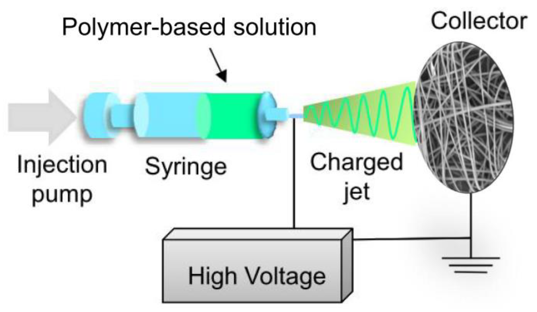
The electrospinning technology exploits electric forces to draw charged threads of a viscoelastic fluid (polymeric solution). The needed experimental setup is very simple and widely accessible. Basically, it consists of a syringe equipped with a needle and a pump to feed the solution, a collector, and a high-voltage power supply (Figure 2). Due to surface tension, a small amount of the fluid pumped out through the syringe needle tends to form a spherical droplet. If a high voltage is applied between the tip of the needle and the collector, the charged liquid droplet elongates assuming a conical shape (Taylor cone) due to electrostatic repulsion between the charges inside it. When the applied voltage is sufficiently high, the electric field force overcomes the surface tension and, if the molecular cohesion of the liquid is sufficiently high, a stable charged liquid jet is ejected from the apex of the cone. The jet continues to decrease in diameter until it starts to bend and enters an instability regime. As a result, it undergoes a continuous elongating-and-whipping process leading to the formation of a long and thin thread that finally deposits onto the collector. Since the solvent almost completely evaporates during the motion of the jet towards the collector, a non-woven mat of solid fibers is obtained by this process [5,12,14,15,45].
Nowadays, industrial spinners are commercially available and able to produce a continuous spun layer having an effective width of 1.6 m. Depending on the specifics required by the application for which the fibers are designed, spinners with different nozzle number and/or symmetry (single- or multi-nozzle, uni-, multi-, or co-axial nozzle spinners), as well as collectors with different shapes (plate-, disk-, or drum-collectors), can be utilized [15].
Multi-needle and needle-less systems allow for higher productivity with respect to the conventional electrospinners, whereas by the use of co-axial systems, in which precursors are fed through separate co-axial channels, hollow, or composite core-shell nanofibers with additional functionalities can be produced [4]. Mats consisting of uni-axially aligned rather than randomly-oriented fibers can be obtained by utilizing rotating drum-collectors in place of the conventional plate, or by the aid of suitably applied magnetic or electric fields [3]. Besides, through rational design and/or patterning of the collectors, nanofibers with very complex orientation patterns can be prepared [3]. Two separate polymer solutions can simultaneously and independently be spun on a same rolling collector thanks to the horizontally-opposed blending electrospinning method to achieve a bi-component fibrous mat.
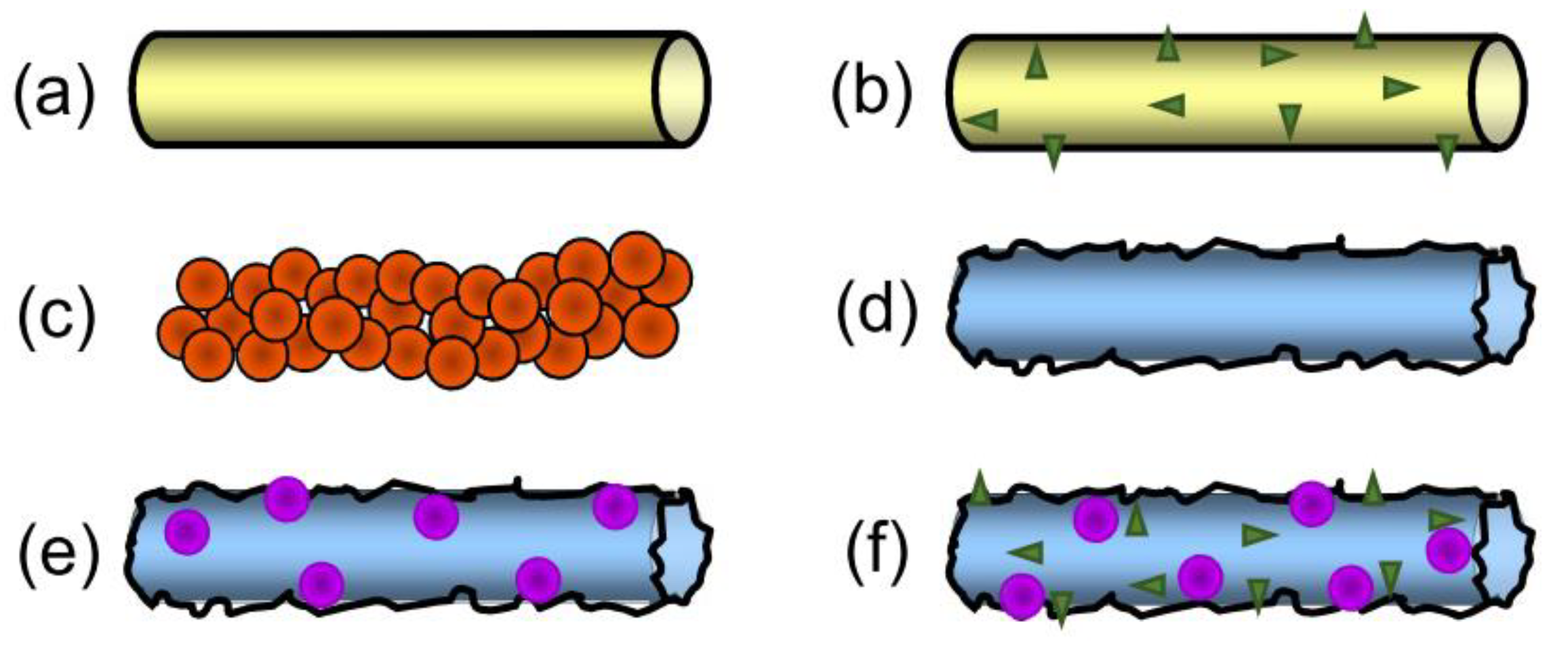
Also, manifold are the ambient, instrument, and solution parameters that can be tuned in order to obtain the desired fiber properties (temperature, atmosphere, humidity, needle gauge, needle-tip/collector distance, solution feeding-rate, applied voltage, nature and molecular weight of the polymer(s), polymer mass-ratio in the case of blend, type and relative amount of the solvent, addition of precursors, preformed nano-sized components or sacrificial templating agents and their relative-to-polymer amount, use of conductive additives). At last, a single-step (calcination) or multi-step post-spinning heat treatment (stabilization and carbonization, sometimes followed by activation) upon different atmospheres (air, inert gases, gas mixture, activating gases) can be necessary to finalize the production process of the various fiber typologies (Figure 3). Polymer fibers do not require any treatment [46,47]; pure (and doped) oxide fibers are obtained by removing the organic component of the precursor(s) via an oxidative process [48,49,50,51], whereas stabilization of the polymer enabling its subsequent processing at higher temperature for graphitization is needed to obtain carbon and composite carbon-based fibers [52,53,54,55,56,57,58]. Activation upon gaseous atmosphere [53] or chemical etching to remove sacrificial templating agents [59] are utilized to enhance the fiber porosity and surface area. The produced ENMs can be in the form of powders (oxide fibers), self-standing non-woven membranes (polymer fibers), or self-standing flexible paper-like membranes (carbon and composite carbon-based fibers).
For the sake of completeness, it has to be mentioned that, in the latest years, several novel alternative strategies to fabricate nanofibers are emerging, such as plasma-induced synthesis, CO2 laser supersonic drawing, electro-hydrodynamic direct writing, solution blow spinning, and centrifugal jet spinning. The readers interested in this subject can refer to reference [5].
In the following, an overview of some energy-related applications of ENMs is given. Recent advances in the field of rechargeable alkali metal-ion batteries, redox flow batteries, metal-air batteries, and supercapacitors are illustrated. Also, reactors for water desalination via capacitive deionization (based on energy storage) and for hydrogen production by water splitting, as well as nanogenerators for energy harvesting and textiles for energy saving through personal thermal management, exploiting EMNs, are briefly presented.
3. Rechargeable Lithium-Ion and Sodium-Ion Batteries
Nowadays, energy and environment represent key factors for the social development and long-term survival of human beings. The increasing energy demand associated with the growth of the world population and the enhancement of living standards, coupled to the need for decreasing greenhouse gas (GHG) emissions to limit effects on environmental pollution, global warming, and climate changes and to the progressive depletion of fossil-based resources, has strongly encouraged the utilization of clean and renewable energy sources. However, the stochastic and discontinuous nature of these sources calls for the use of efficient energy storage systems (EESs) to be settled in the electrical grid distribution [60]. The development of cost-effective, efficient, and large-scale EESs for the expected coming growth of renewable energy production is one of the key challenges of the 21st century.
Among the different EESs, those based on electrochemical methods, such as the rechargeable electric batteries, represent one of the most interesting alternatives because they are suitable to meet the different needs of power supply, while offering other intrinsic advantages, such as the compact size and the lack of emissions associated with their operation. Globally, electric batteries account for a total power of ~2.2 GW [61]. Among them, lithium-ion batteries (LIBs), which deliver 1.7 GW [61], presently represent the primary EES systems, with a production higher than 100 million cells/month and about 1500 tons/month of electrode materials. They are widely utilized to power small/portable electronic devices, as well as hybrid and fully electric vehicles; thanks to the recent advances, LIBs might also represent a viable solution for bulk EES at power stations and load leveling of renewable sources.
3.1. Lithium-Ion Batteries
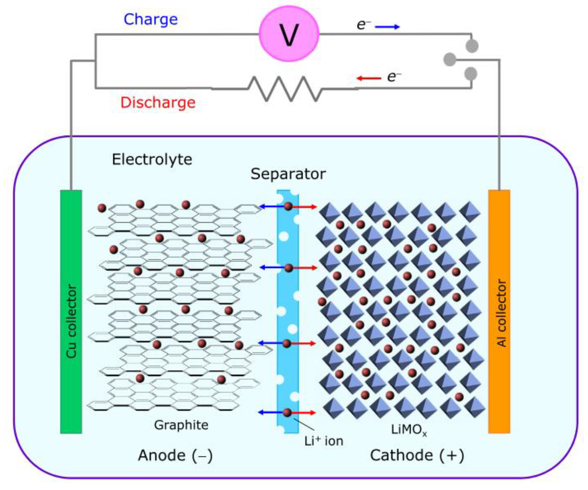
As sketched in Figure 4, a LIB cell consists of anode (e.g., graphite), cathode (e.g., a Li-containing transition metal oxide, LiMO2, with M standing for Mn, Fe, Co, or Ni), and a separator permeable to the ions and the electrolyte (e.g., LiPF6 in an organic solvent). It is able to supply energy thanks to the spontaneous oxidation-reduction reactions occurring at the electrodes. During the charging process (de-lithiation), energy is supplied by an external source; Li+ ions are extracted from the cathodic material, diffused in the electrolyte, and enter the anodic material (according to the reaction Cx + LiMO2 → Li(1−y)MO2 + CxLiy, in the case of a traditional LIB [62,63]), while electrons are transferred to the positive electrode through the external circuit. In the discharge process (lithiation), the opposite process takes place (i.e., Li(1−y)MO2 + CxLiy → Cx + LiMO2, in the considered example): Li+ ions, extracted from the anodic material, are re-inserted into the lithiated cathodic material, and the cell provides energy.
The gravimetric capacities of the commonly used electrodes (372 mAh/g for graphite and 274–286 mAh/g for LiMO2 [64]) are inadequate to meet the ever-increasing requirements for ESS devices. The search for alternative highly performing, durable, low-cost, and eco-friendly electrode materials is continuously progressing. As for the anodes, the focus is mainly on transition metal oxides MOx [56,65,66,67,68], which store Li+ ions through the conversion reaction MOx + 2x Li+ + 2x e− ↔ M0 + x Li2O, and IV group elements M0 [69,70,71,72,73] that are able to store larger amount of Li+ ions through the alloying reaction M0 + y Li+ +y e− ↔ LiyM [74], whereas transition metal oxides with olivine structure seem to be promising materials for cathodes [75]. However, some problems limiting the performance and life of the new electrode materials and thus hampering their commercialization still need to be solved. Various strategies have been proposed to enhance electronic conductivity and to reduce pulverization of the active material, to limit the use of inactive battery components (binder and current collectors), as well as to meet the additional requirements imposed by the development of flexible electronics. It is widely recognized that carbon incorporation and nano-sizing improve the electrochemical and mechanical performance of the electrode materials [72,76,77,78,79], providing them with enhanced electronic conductivity and increased resistance against the large volume changes, from which they suffer during the lithiation/de-lithiation process. It has been further shown that the use of binder-free self-supporting flexible carbon-based membranes as electrode materials [56,57,58,66,80,81,82,83,84] translates into a beneficial reduction of the inactive weights with a consequent gain in the effective gravimetric and volumetric capacities of the batteries. These benefits are of crucial importance in manifold applications including transportation, aerospace, and portable and wearable electronics.
Electrospinning is a viable route to simultaneously implement all these ameliorative strategies. Therefore, it has been increasingly and extensively utilized for the production of all the battery components—not only anodes [12,56,57,58,72,74,81,82,84,85,86,87,88,89,90,91] and cathodes [12,92,93,94,95], but also electrolytes [12,96,97,98] and separators [12,99,100], which makes it feasible to manufacture secondary batteries by assembling components produced exclusively by electrospinning (Figure 5).
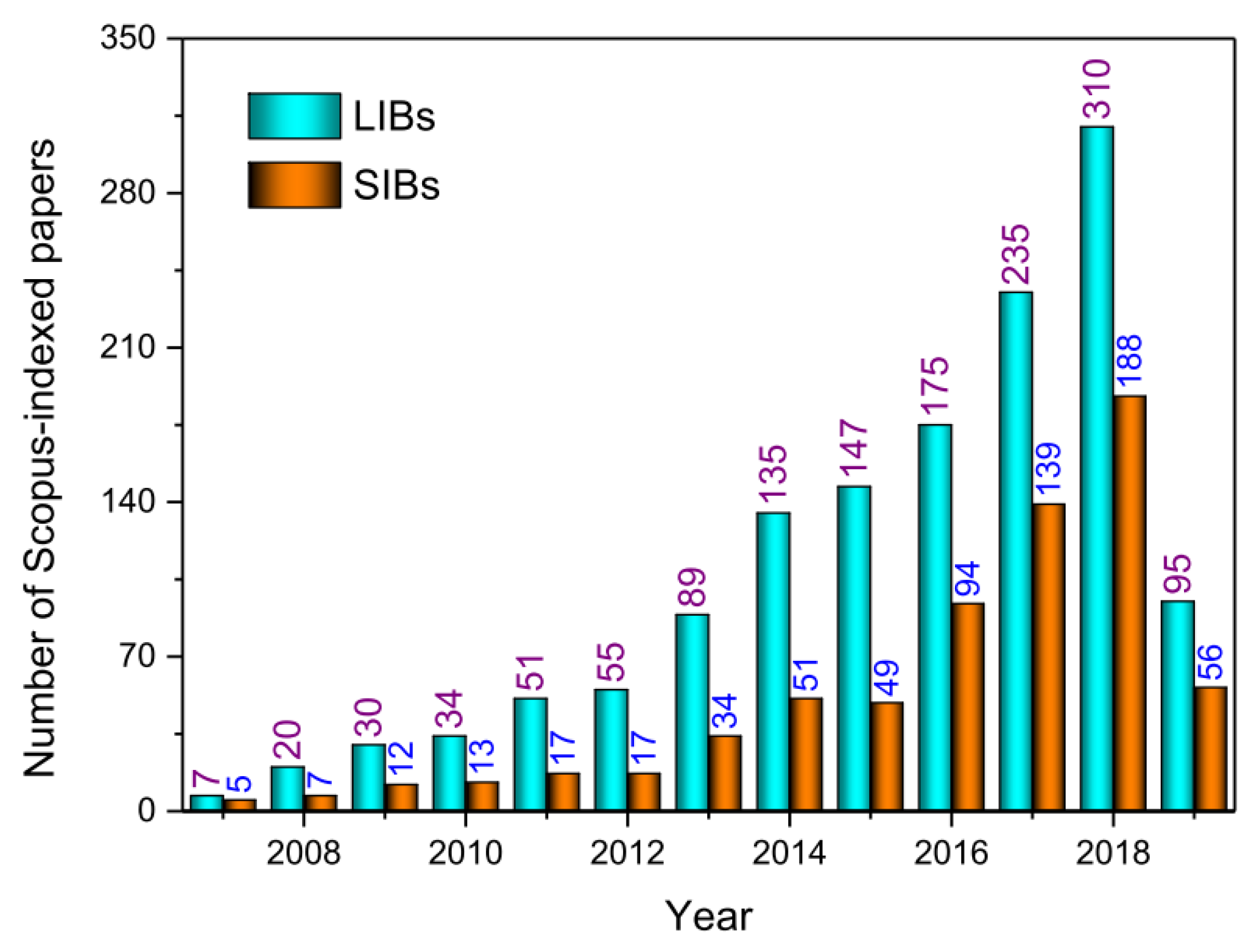
Actually, the increasing number of published papers focused on this subject witnesses the growing interest of the scientific community for the use of this technique in the manufacturing of LIB components. Figure 6 displays the numbers relative to a single database. Several exhaustive review papers are available in the literature that report the outstanding electrochemical properties that suitably engineered ENMs exhibit compared to the commercial references (see f.i. [10,11,12,14,15,18,101], just to cite a few of them).
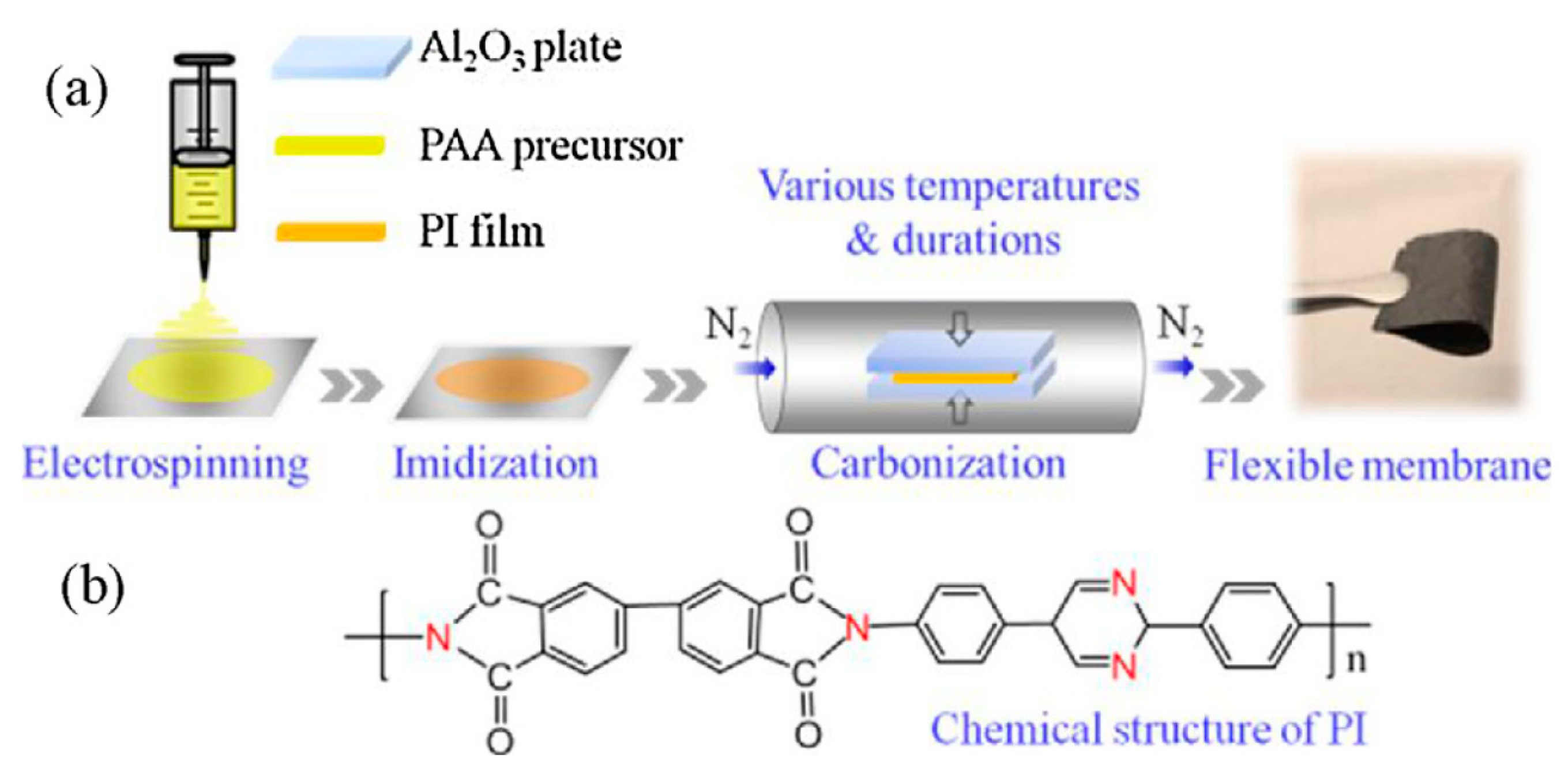
Indeed, the LIB-technology exploiting ENMs continuously progresses thanks to the incessant efforts made to enhance their performance and to render easier and more efficient their production process. For instance, Zhao et al. [80] have recently proposed to utilize polyimide (PI), in place of the commonly selected polyacrylonitrile (PAN), to fabricate flexible self-standing paper-like electrospun carbon membranes. According to Zhao et al., the oxidative stabilization, through which PAN is converted to an infusible stable ladder polymer [102], is a slow and not easily controllable step, whereas PI, containing aromatic heterocyclic rings with semi-ladder structure, can be easily obtained through a thermal or chemical imidization process from the polyamic acid (PAA) precursor [80]. Flexible self-standing paper-like electrospun nitrogen-doped carbon fibrous membranes produced via the multi-step process schematically illustrated in Figure 7a, using PI with biphenyl and pyrimidine rings (Figure 7b), are able to deliver a reversible specific capacity of 695 mAh/g at a rate of 0.1 A/g. This value is higher than that reported, at the same rate, by Dufficy et al. [78] for composite anodes consisting of PAN-derived carbon fibers enriched with thermally reduced graphene oxide. Flexible anodes derived from heterocyclic PI further exhibit good stability, retaining 245 mAh/g after 300 cycles at a rate of 1.5 A/g [80].
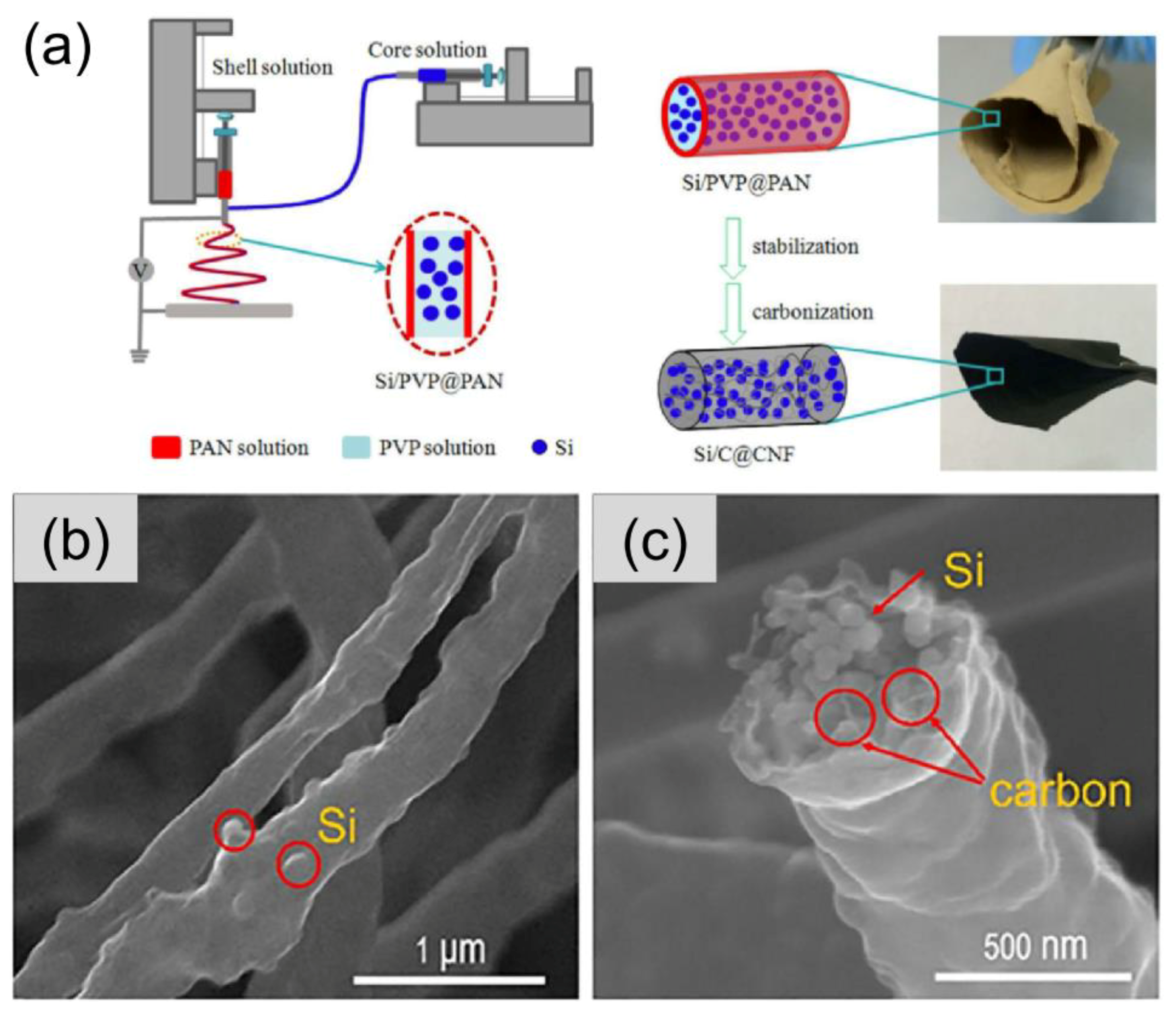
Owing to the very high theoretical specific capacity of silicon (4200 mAh/g), carbon fibers with embedded Si nanoparticles (NPs) have received great attention as a possible solution to the rapid capacity fading caused by the pulverization of the bare silicon electrode due to its mechanical failure upon repeated Li insertion and extraction. In particular, Xu et al. [82] have designed flexible non-woven membranes consisting of electrospun silicon/carbon@carbon fibers (Si/C@CNFs). The fibers, fabricated by the use of a co-axial electrospinning configuration (Figure 8a), exhibit a core-shell structure (Figure 8b–e), where the external shell is constituted by PAN-derived carbon, and the internal core consists of well-dispersed Si NPs wrapped to PVP-derived carbon. The Si/C core acts as an efficient conductive network (Figure 8f), enabling the membranes with 40 wt% Si loading to deliver up to 1507 and 555 mAh/g at current densities of 0.1 and 2 A/g, respectively [82]. Thanks to the buffering action of the PVP-derived carbon protecting Si NPs from the mechanical damage, after 500 cycles at a rate of 0.2 A/g, the electrode retains 86% of the initial capacity.
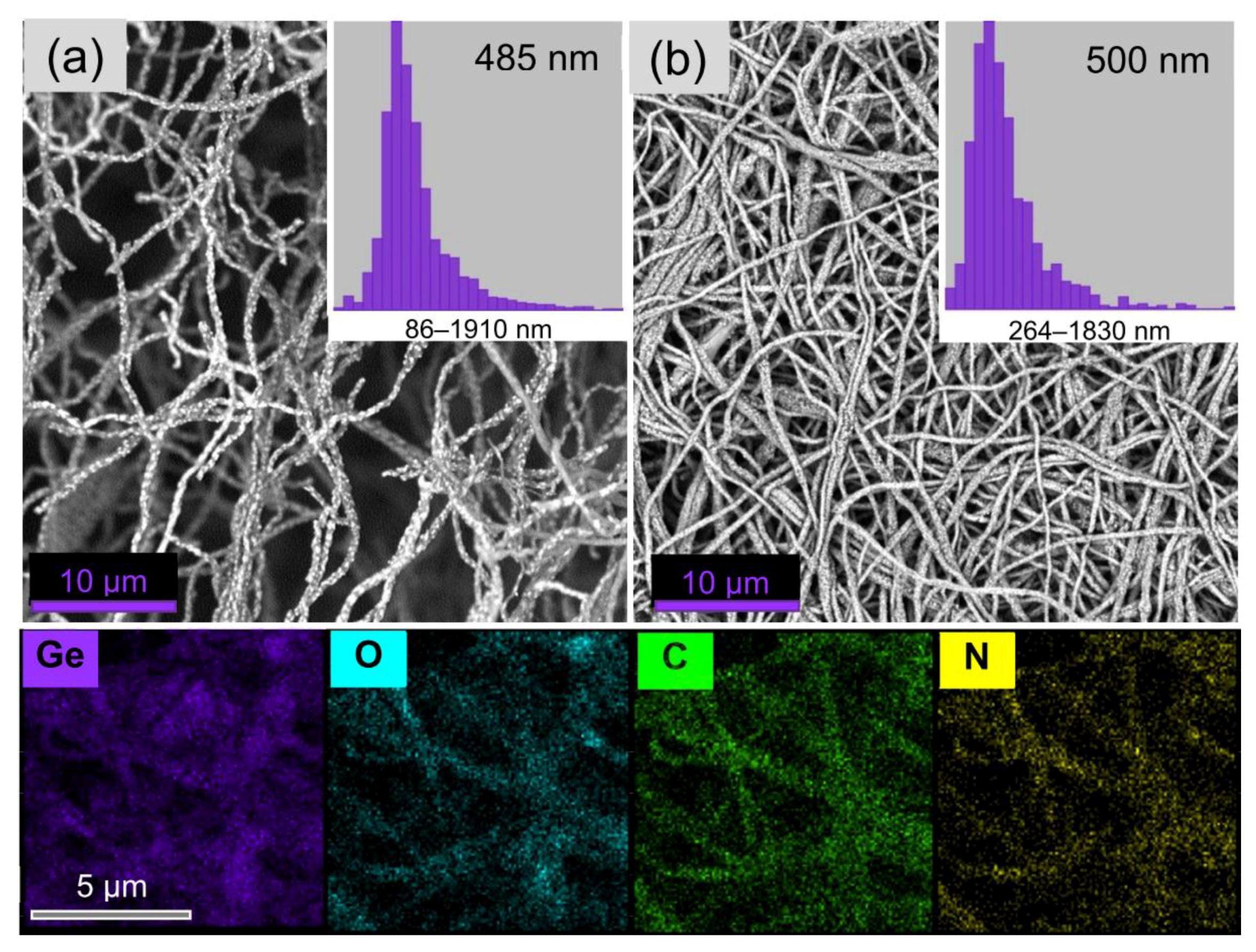
Although flexible self-supporting paper-like fibrous membranes synthesized via electrospinning need neither binders nor metal substrates as current collectors, conversely, their open and loose structure, affording Li+ ion diffusion and strain accommodation, results in low-density and, hence, in a low volumetric specific capacity of the electrode. Recently, Pantò et al. [57] have demonstrated that the hollow space within the fibers can be noticeably reduced by cold pressing the as-membrane. This extremely simple procedure that allows for obtaining rigid self-standing membranes having a more compact and tight structure (compare Figure 9a,b). In the case of nitrogen-doped carbon fibers encapsulating GeOx NPs (bottom of Figure 9), the anodes are able to deliver initial discharge volumetric capacities up to 3580 mAh/cm3 [58].
Although some unsolved problems persist and further ameliorative actions are still needed [58], the efforts spent by the Scientific Community in this research field ensure the full exploitation of the huge ENM potential in the near future.
Nonetheless, different aspects also deserve consideration. The advancement of LIB technology, alone, is not sufficient for a LIB-based economy. It is of fundamental importance that the future systems for EES, besides exhibiting outstanding electrochemical performance to meet the ever-increasing market requirements, also be sustainable. Since their first commercialization by Sony in 1991, the pricing of LIBs has continuously been dropping due to the expansion of worldwide production capacity, increased by 11% between 2015 and 2016 [103], and oversupply of the produced power (only 40% of available 53 GWh produced in 2015 was used [104]). However, due to the LIB penetration in automotive and on-grid storage markets and the consequent increasing consumption of lithium, this trend is destined to reverse. Moreover, at the average 5% yearly growth rate in lithium mining necessary to pace up the demand increase, reserves are expected to encounter a severe shortage in less than 65 years [105], with consequent serious concerns for the future production costs of lithium raw material. This is the reason why, in the latest years, a growing interest has been focused on secondary batteries based on different alkali metal ions (i.e., sodium [105,106,107,108,109,110] and, more recently, even potassium [109,111,112,113,114,115]) with similar chemistry to lithium.
3.2. Sodium-Ion Batteries
The use of sodium would remarkably reduce storage costs since its resources are more abundant and better distributed on Earth. A study based on a prospective life-cycle-assessment has demonstrated that sodium-ion batteries (SIBs), showing, per kWh of storage capacity, impacts at the lower end of the range reported for current LIBs [116], represent a more sustainable, cost-effective, and eco-friendly alternative to LIBs in the energy- and climate-related challenges of the 21st century. Of course, many efforts are still required to meet the increasing demands of the market on zero-emission electric vehicles and on-grid energy storage and to fill the gap between LIB and SIB technology. The development of SIB technology requires the identification/design and preparation of new electrode materials with reversible Na+ intercalation/conversion/alligation reaction to reduce the technological gap with LIBs.
In principle, in spite of the higher weight of sodium compared to lithium (23 g/mol against 6.9 g/mol), its higher standard electrode potential (−2.71 V vs. SHE against −3.02 V vs. SHE for lithium) and the larger size of its ions (1.02 Å against 0.76 Å), the transition from LIBs to SIBs should not cause any consequence in terms of energy density, since the capacity primarily depends on the characteristics of the nanostructures acting as electrodes [105].
Various materials have been evaluated as cathode materials for SIBs obtaining interesting results, in terms of stability and charge retention [105,117,118,119]. They include layered sodiated transition metal oxides (Na1−xMO2, where M stands for Ti, V, Cr, Mn, Fe, Co and Ni, Ru) with O3- and P2-type structure (for x close to 0 or in the range 0.3–0.7, respectively) and their derivatives, layered transition metal oxides and fluorides, transition metal polyanion materials, phosphates, fluorophosphates, pyrophosphates, mixed phosphates, carbonophosphates, sulfates, fluorosulfates, cyanides, and organic compounds, with theoretical (measured) specific capacities ranging between 79 and 710 mAh/g (30 and 300 mAh/g) [105].
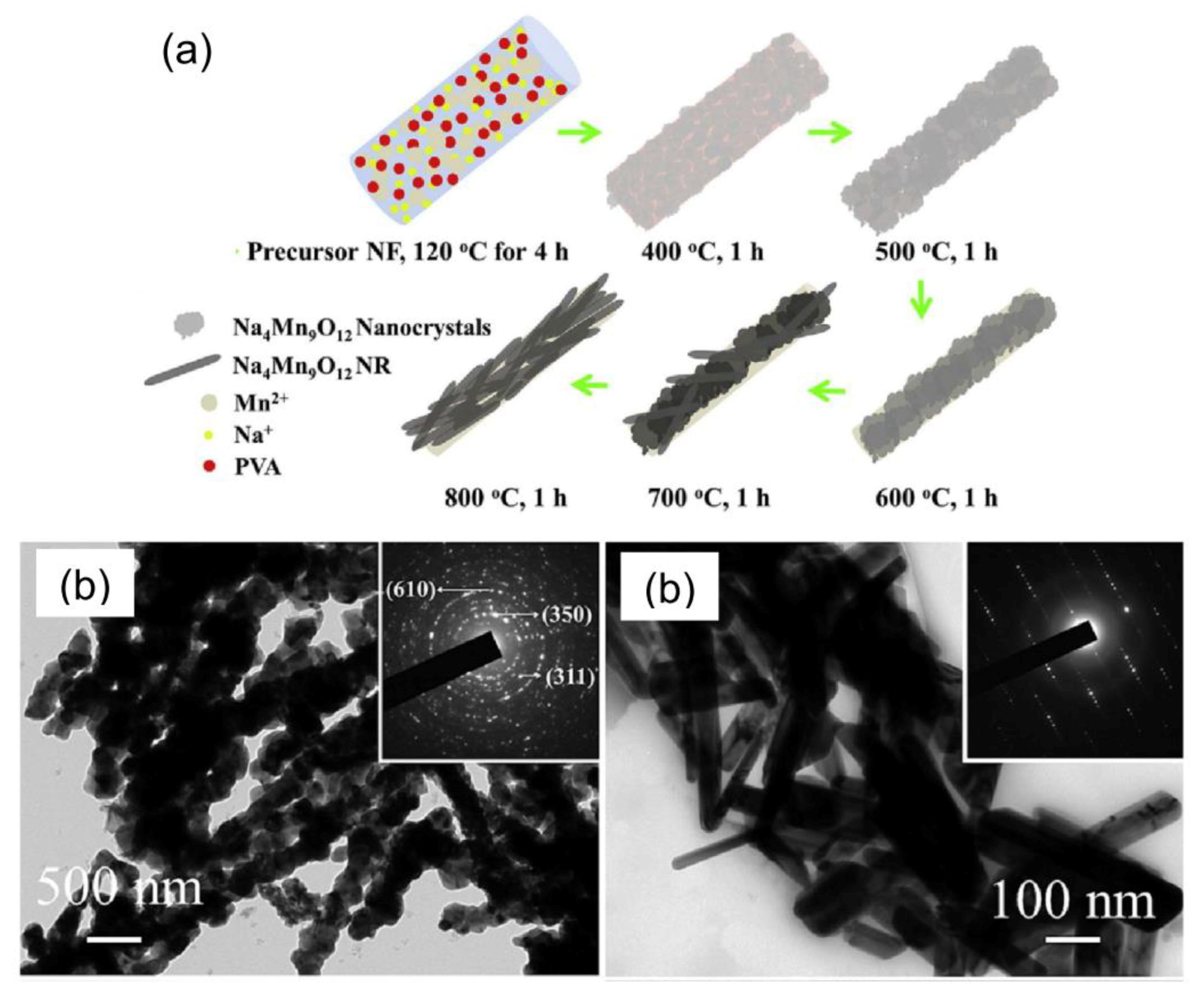
Table S1 reports some examples of ENMs for SIB cathodes and their preparation conditions; the main parameters describing their performance are reported in Table S2. Polyvinyl pyrrolidone (PVP) [120,121,122,123] and polyvinylacetate (PVAc) [124,125] are frequently used as polymers for the preparation of the spinnable solution. The fibers of sodiated transition metal oxides, obtained after thermal removal of the organic component of the as-spun fibers, generally consist of interconnected building blocks, whose shape may evolve with changing the heating temperature (Figure 10) [120,122,124].
As in the case of LIBs, the preparation of the working electrode by utilizing these kinds of materials (in the form of powders) requires the use of binder and carbonaceous additive (Table S2). Besides, a current collector is necessary to complete the SIB assembly. On the contrary, paper-like flexible membranes, consisting of carbon fibers encapsulating very small-sized oxide particles (Figure 11), can be directly used as self-supporting working electrodes—they do not need any binder, conductive additive, and collector [123,125,126,127], which improves the overall energy density of batteries. These cathode materials generally offer a variety of advantages and exhibit relevant electrochemical performance for Na-storage. For instance, the self-standing membranes formed by a non-woven network of composite NaVPO4F/C fibers synthesized by Jin et al. [123] are able to deliver a reversible capacity of 103 mAh/g at a rate of 1 C, and to retain 56 mAh/g even at a very high rate (50 C), further exhibiting a ultra-long cyclability with 96.5% capacity retention after 1000 cycles at 2 C. The shortened length of Na-ion transport associated to the very small size of the oxide particles, together with the fiber porosity, favoring the permeation of the electrolyte, and the material structure consisting of a three-dimensional network of interconnected fibers that results in improved ionic and electronic transport, is responsible for this behavior [123].
Different from cathode materials, for which satisfactory results in terms of stability and charge retention have been achieved [105], anode materials still represent a challenge [128]. Graphite, the standard anode material for LIBs, exhibits poor performance in SIBs since Na+ ions hardly intercalate between its layers because of the energetic instability of the Na-graphite intercalation compounds [105,129]. Non-graphitic disordered anode materials, such as hard carbons, where the enlarged interlayer spacing and/or the smaller size of the parallel graphitic domains allows for the sodium insertion, are currently utilized. Recently, self-standing membranes consisting of fulvic acid-based electrospun hard-carbon nanofibers have been evaluated as binder- and collector-free anode materials [130]. They have shown a reversible sodium intercalation capacity of 248 mAh/g with a capacity retention ratio of 91% after 100 cycles at a current density of 100 mA/g. The proper interlayer distance, coupled with the abundance of oxygenated functional groups and benefits deriving from the high aspect-ratio morphology of the electrospun fibers (i.e., short ion diffusion distance and excellent stress tolerance) account for their good storage performance.
However, since the production of hard carbons generally has great environmental impact [116], different, more eco-friendly anode materials have been recently investigated for rechargeable SIBs [117,128,129,131].
Conversion materials, such as transition metal oxides (TMOs) and transition metal sulfide (TMSs), conversion-alloying materials, such as transition metal phosphide (TMPs), and alloying materials, such as elements of the 14th and 15th groups in the periodic table, have received particular attention [105,129,131]. The highest theoretical capacity (~2600 mAh/g) pertains to phosphorus. Nevertheless, the large volume changes (up to ~400%) undergone by the alloying materials during the sodiation/de-sodiation process, with consequent electrode pulverization and rapid capacity fading, is still an unresolved problem, which hampers their use in practical applications [105,131]. Conversely, TMSs and TMOs exhibit still high theoretical capacities (up to ~900 and ~1000 mAh/g, respectively) and the main limitations of their use as anode materials, namely structural damage leading to pulverization and poor electronic conductivity, can be effectively tackled with nano-sizing [132,133], confinement in a carbonaceous matrix [131,134,135,136,137,138,139], and doping with aliovalent elements [140].
Tables S3 and S4 respectively report the preparation conditions of some ENMs for SIB anodes and the main parameters describing their performance. As in the case of LIB anodes, PAN [130,133,135,136,140,141] and polyvinyl PVP [134,137,138,139] are the polymers most frequently selected to prepare the spinnable solution, whereas polymethyl methacrylate (PMMA) generally acts as a sacrificial pore-forming agent [136,141].
As for anode materials consisting of electrospun TMO-fibers, the high aspect ratio fiber morphology is responsible for the interestingly high initial specific capacity (983 mAh/g) recently reported for spinel cobalt oxide (Co3O4) fibers [133]. However, after the first sodiation/de-sodiation cycle, their capacity lowers down to 576 mAh/g as an effect of the formation of CoO as a stable intermediate. The CoO-based anode retains 71% of its initial capacity over 30 cycles [133].
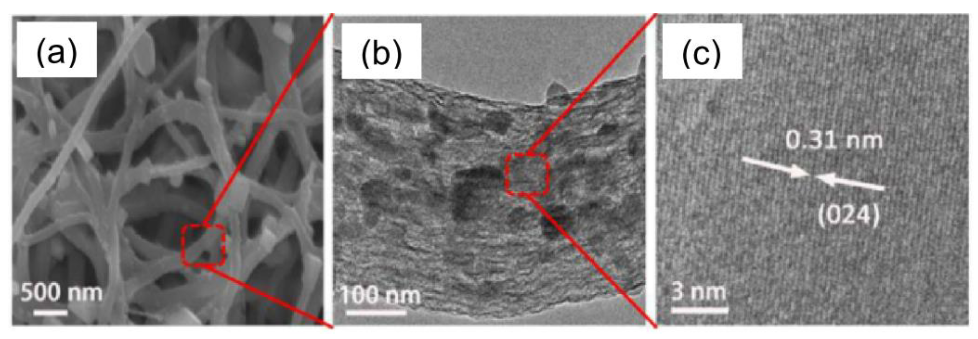
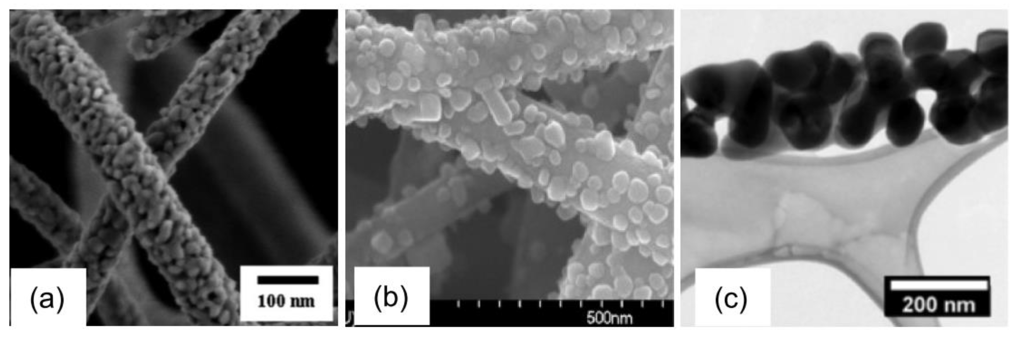
Anodes based on electrospun iron(III) oxide fibers doped with silicon exhibit better stability [140]. They are able to deliver 350 mAh/g after 70 cycles retaining 85% of the initial capacity—a result never achieved for iron oxide-based electrode standard formulation. The doping with an aliovalent element induces changes in the crystalline phase of the oxide and in its morphology, as well. The undoped fibers consist of interconnected polycrystalline hematite (α-Fe2O3) grains (Figure 12a), whereas the Si-doped fibers are constituted by elongated maghemite (γ-Fe2O3) nanostructures developing mainly along the longitudinal fiber axis (Figure 12b).
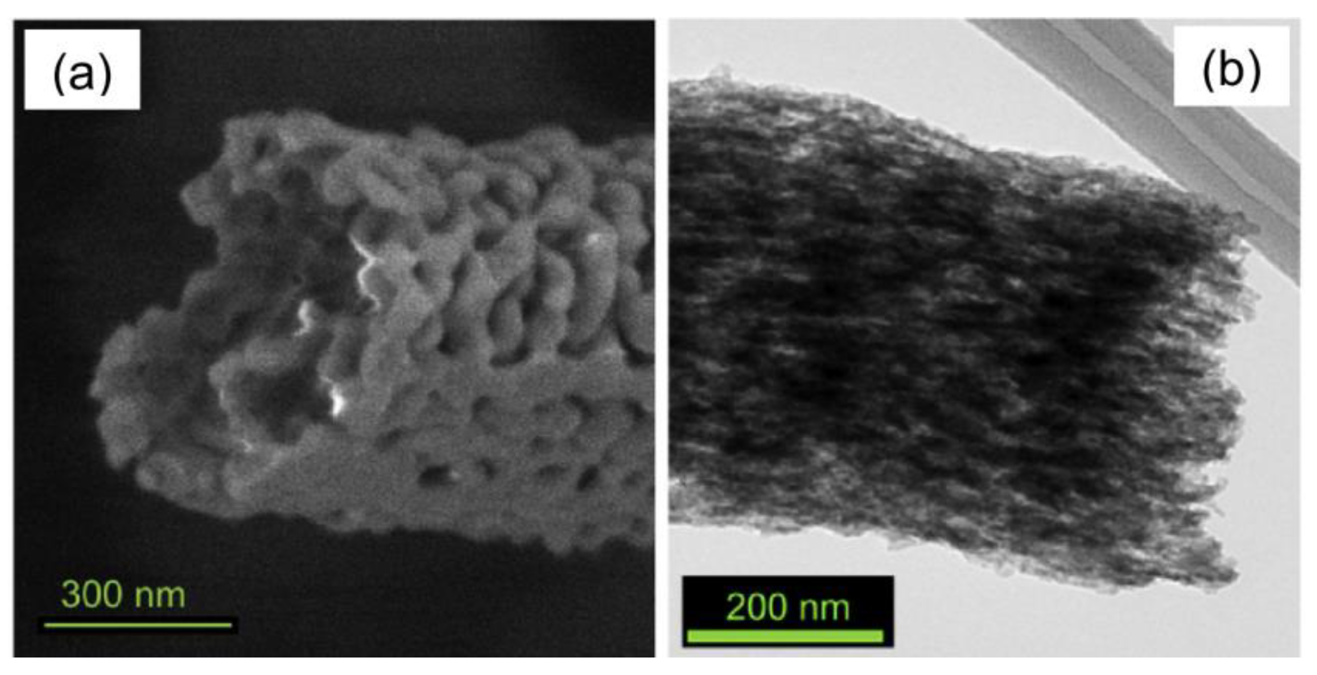
The latter change is responsible for the improved cyclability, while the formation of γ-Fe2O3, an intrinsically more conductive phase, accounts for the enhanced electrochemical performance with a specific capacity (400 mAh/g at a rate of C/20) higher by a factor of ~4 compared to the α-Fe2O3-based electrode [140]. Electrodes based on γ-Fe2O3 NPs with standard formulation (Table S4) exhibit worse performance too, with lower stability and smaller delivered capacity (~150 mAh/g after 50 cycles) [136]. Instead, in free-standing γ-Fe2O3/C fibrous membranes, prepared by using PMMA as a sacrificial agent to generate pores in the nitrogen-doped PAN-derived carbon fibers (Figure 13), the electrochemical behavior benefits from γ-Fe2O3 NPs being embedded in high aspect-ratio carbon-fibers [136], often reported as one-dimensional (1D) nanostructures. After 50 cycles at 0.1 C, the binder-free electrode still delivers 290 mAh/g.
By far, greater stability pertains to anodes based on electrospun carbon fibers containing anatase NPs (Table S4). TiO2/C fibers are able to deliver 240 mAh/g at 0.2 A/g with capacity retention close to 100% over 1000 cycles [134]. Over the same number of cycles, thanks to the synergistic interaction between anatase and tin NPs (Figure 14), TiO2-Sn/C fibers deliver a lower reversible capacity (191 mAh/g) at a higher current density (1 A/g) with comparable capacity retention (95.4%) [137].
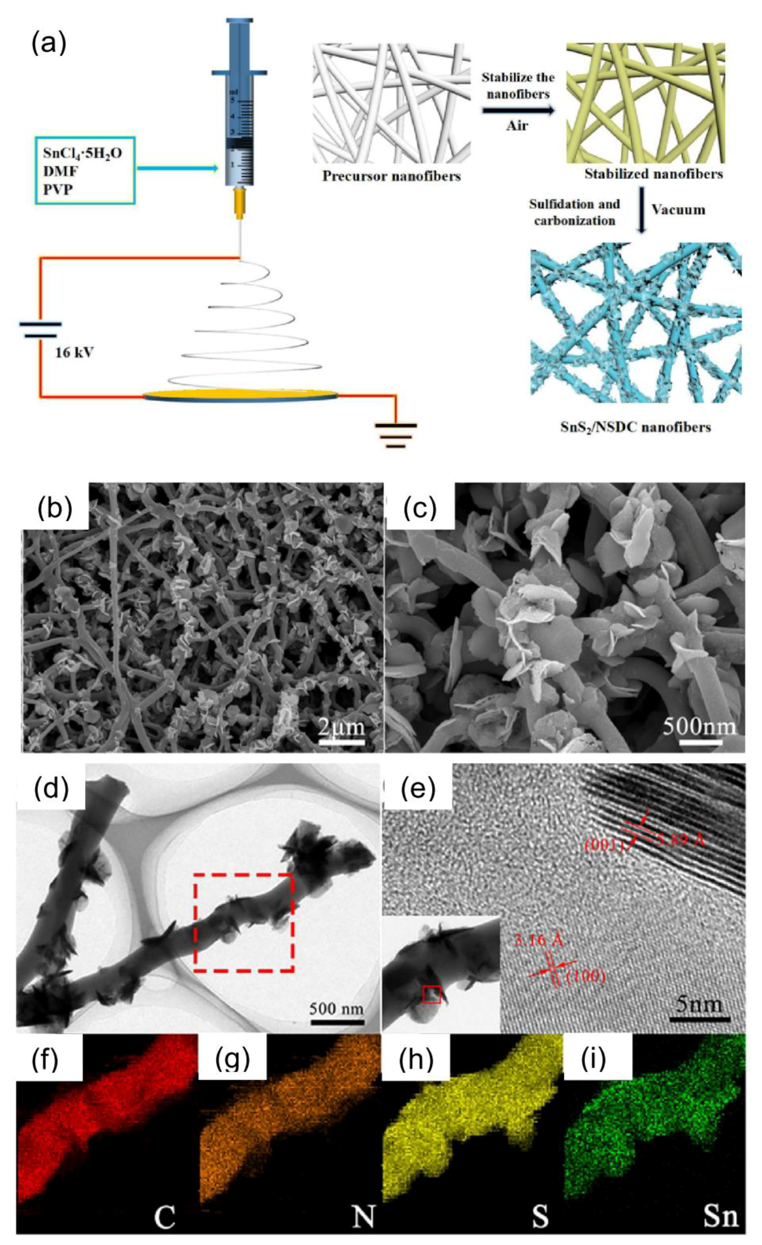
Very recently, Xia et al. [139] have proposed a four-step process to prepare composite tin disulfide/N- and S-doped carbon nanofibers. As schematically depicted in Figure 15a, the process consists of (i) electrospinning, followed by (ii) stabilization in the air, (iii) sulfidation, and (iv) carbonization in a vacuum. It allows for the production of dual-doped carbon fibers encapsulating crystalline SnS2 NPs and decorated by crystalline SnS2 nanosheets (Figure 15b–f). In Na+ ion half-cell, the electrode prepared by the use of these fibers delivers reversible capacities of 380 mAh/g at 0.5 A/g after 200 cycles and of 310 mAh/g at a remarkably higher current density (4 A/g). Moreover, at a low rate (50 mA/g), the Na+ ion full-cell prepared by coupling pre-sodiated SnS2/N,S-C fibers with Na2.3Cu1.1Mn2O7-δ-based cathode (with 100 mAh/g specific capacity) is able to power 24 red LEDs (light emitting diodes) operating at 2 V, since it delivers an initial discharge capacity of 350 mAh/g, and after 50 cycles it exhibits a capacity retention of 61% (corresponding to a delivered capacity of 213 mAh/g) [139]. The good electrochemical performance of the SnS2/N,S-C fibers originates from the synergy between inherent advantages of their high aspect-ratio morphology (short diffusion length and ability to buffer volume changes) and doping with heteroatoms, which further enhances the electrical conductivity of the carbonaceous matrix.
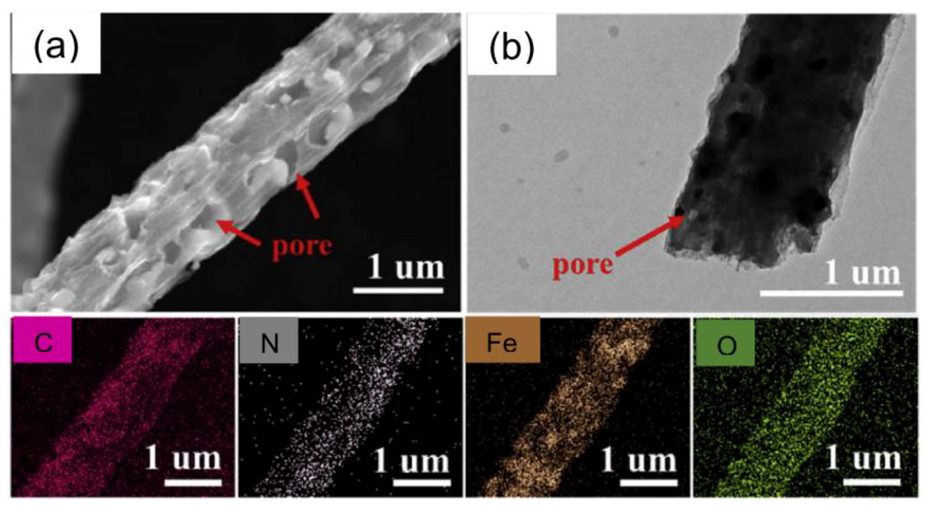
Liu et al. have reported better results, in terms of cycling life, for binder- and collector-free membranes consisting of electrospun porous N-doped carbon fibers encapsulating Sn [141] and MnFeO4 [135] nanodots with typical sizes of 1–2 nm and ~3.3 nm, respectively. The former electrodes deliver reversible capacities of 633 and 450 mAh/g at rates of 0.2 and 10 A/g, respectively; besides, they retain 483 mAh/g over 1300 cycles at 2 A/g [141]. Conversely, the latter exhibit slightly lower capacities (504 and 305 mAh/g at rates of 0.1 and 10 A/g, respectively), but impressively longer cyclability, delivering 360 mAh/g (corresponding to capacity retention of 90%) after 4200 cycles [135].
4. Secondary Redox Flow Batteries
As mentioned above, the predicted severe shortage of the lithium reserves in less than 65 years [105] will result in serious concerns for the future production costs of LIBs, whereas the SIB technology has not reached the needed maturity yet. In this scenario, the secondary redox flow batteries (RFBs) gather great interest among the traditional large-scale EESs. They can convert chemical energy into electricity by the oxidation-reduction reactions of positive and negative reactants [142]. Thanks to their excellent performance in terms of efficiency, life cycle, environmental friendliness, and low toxicity, particular attention is devoted to vanadium-RFBs, considered prospective future EESs since vanadium is more abundant in nature than lithium and its cost is much lower. In a first-generation vanadium-RFB [143], positive (VO2+/VO2+ sulfate) and negative (V2+/V3+ sulfate) electrolytes are stocked in tanks, and a proton-exchange membrane separates the electrodes in the reaction cell (Figure 16). The energy conversion in the cell occurs through the chemical reaction VO2++ H2O + V3+ ↔ VO2+ + 2H+ + V2+ (E0 = 1.26 V), with VO2++ H2O ↔ VO2+ + 2H+ + e− (E0 = 1 V) and V3+ + e− ↔ V2+ (E0 = −0.26 V) reactions taking place at the positive and negative electrode, respectively [142,144,145].
Since the mid-1980s, when the research on vanadium-RFBs began [143], new generations of systems have been proposed to improve the stability and the solubility of vanadium ions over a wider range of temperature [142]. Second-generation vanadium-RFBs utilize a mixture of vanadium chloride and vanadium bromide as the electrolyte, whereas third-generation systems operate with mixed H2SO4/HCl electrolyte solutions in both half-cells [142].
Advances and prospects in the field of RFBs have exhaustively been illustrated in the literature (see f.i. [142,146]). The strength point of such systems is that the battery capacity can be increased by scaling up the tank volume to contain larger amounts of electrolytes, and the power output can be increased by adding more reaction cells. However, the performance of a battery ultimately depends on its components.
Various types of membranes are used in the RFBs. Among them, commercial (cation exchange) Nafion membranes are widely utilized. They exhibit high chemical stability and excellent electrochemical properties, but, conversely, suffer from high permeability and cost [142]. The poor electrochemical activity of graphite felt (GF), commonly employed as an electrode material, limits the practical application of vanadium-RFBs [145,147]. Although research is still addressed toward carbon-based electrodes due to their low cost, new strategies have been thought up to enhance the electrochemical activity of electrode materials for vanadium-RFBs. Increasing their effective surface area through nanostructuring and accelerating the electrochemical kinetics for redox reactions thanks to the development of novel electrocatalysts represent the usually followed approaches [144]. In all the cases, the use of ENMs appears to be a viable route to improve the RFB performance [148,149,150]. Just to cite some examples, better performance of non-aqueous vanadium acetylacetonate-based RFBs, in terms of coulombic efficiency (CE), energy efficiency (EE), and voltage efficiency (VE), have been obtained at all of the tested current densities thanks to selective membranes fabricated by depositing Nafion/polyvinyl alcohol (PVA) fibers directly on a rotating drum collector wrapped with a porous Celgard 2400 membrane [151]. Compared to the commercial dispersion-cast Nafion NR 212 membrane, the fibrous Nafion/PVA membrane exhibits lower swelling ratio and lower vanadium acetylacetonate permeability.
As for the electrode materials, several interesting results have been achieved by the use of electrospun carbon-based fibers as the negative electrode in RFBs [145,152,153]. Generally, the electrode performance of woven electrospun fibrous membranes is limited by low porosity and poor permeability that hampers the mass-transport during the RFB operation. To tackle this problem in vanadium-RFBs, Xu et al. [152] have designed a freestanding carbon electrode consisting of an electrospun fiber web with ultra large pores. The electrode has been fabricated via the horizontally-opposed blending electrospinning method, involving the simultaneous and independent spinning of two separate polymer solutions (PAN/DMF and PVP/deionized water) on a same rolling collector, followed by PVP fiber removal through a selective dissolution approach and standard two-step (stabilization/carbonization) heat treatment. At 60 mA/cm2 current density, the CE, VE, and EE of the single cell using the so-obtained freestanding electrode reach 95.4%, 81.6%, and 77.9%, respectively. These values are higher than the ones achieved by the use of non-woven fibrous webs.
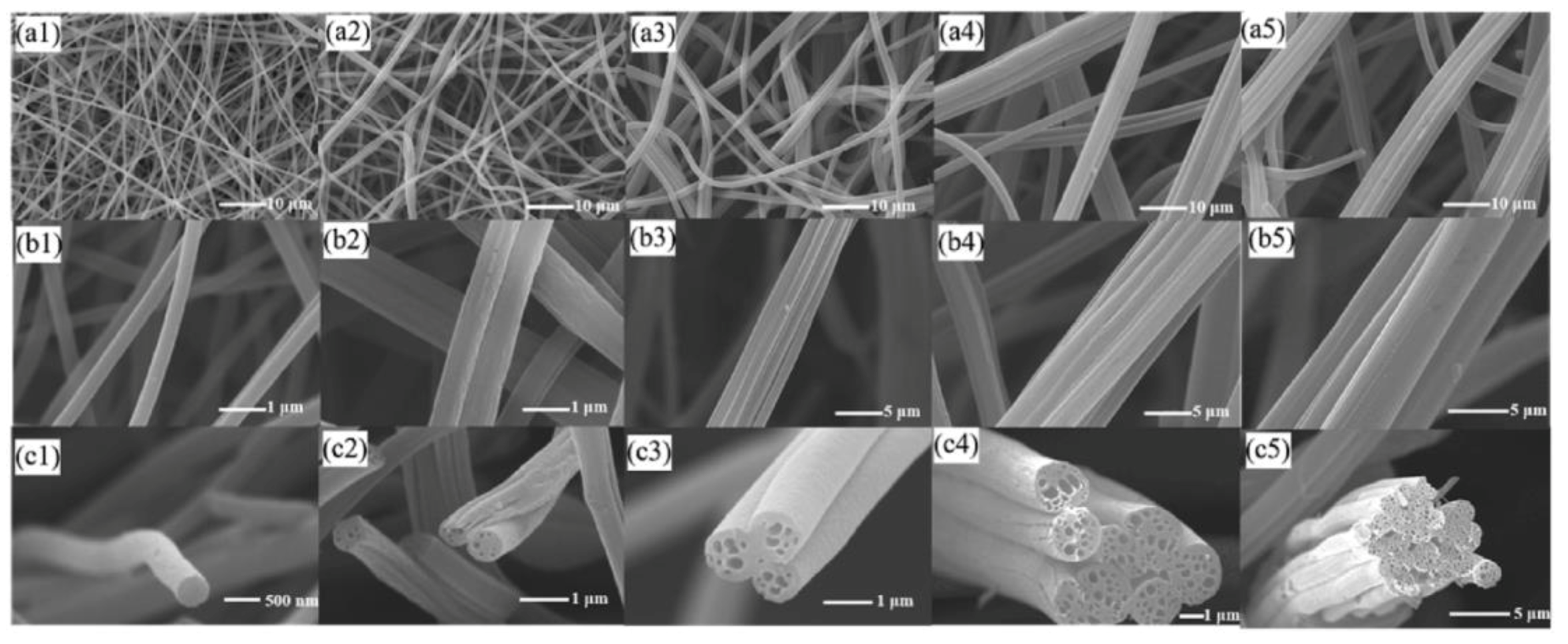
To improve the mass-transport of active electrode species in vanadium-RFBs, Sun et al. [153] have proposed a novel method to fabricate carbon-based electrospun fibrous electrodes endowed with internal channels in each fiber. By a proper tuning of the viscosity of the polyacrylonitrile/polystyrene (PAN/PS) precursor solution leading to self-assembling of the carbon fibers into large bundles, they have prepared porous carbon fiber bundle mats (Figure 17).
The produced bundle structure results in significantly enlarged pore size compared with the traditionally electrospun fiber electrode, whereas the nanochannels formed inside the fibers due to the PS thermal decomposition upon carbonization provide additional specific surface areas. As a result, at current densities of 100 and 200 mA/cm2, the single cell with the as-prepared bundled electrodes achieves nearly doubled discharge capacity and electrolyte utilization, as well as EE values of ~88% and 80%, respectively.
As is widely recognized, nitrogen doping of the active material is beneficial for the wettability and electrocatalytic activity of electrodes [6]. He et al. [145] have synthesized PAN-based nitrogen-doped carbon fibers via electrospinning followed by fiber dispersion in the liquid phase (urea solution, with urea acting as an external nitrogen source) and carbonization at different temperatures (800–1000 °C). Due to the strong electronegativity of nitrogen, doping increases the negative charge density on the carbon fiber surface, facilitating the adsorption of V2+ and V3+ ions and providing active sites for V2+/V3+ couples. Therefore, at 90 mA/cm2, the cell using fibers carbonized at 900°C exhibits a discharge capacity of 98.0 mAh and an EE close to 73%.
In recent years, various noble metal species have been evaluated as alternative materials to the commonly used carbonaceous ones. However, in spite of their good electrocatalytic activity, their cost severely limits any practical applications [154]. Metal oxide-carbon composites, combining electrical conductivity peculiar to carbonaceous materials with the enhanced catalytic properties of the metal oxides, are very promising candidates for electrodes in RFBs. Interesting results have recently been presented by Antonucci’s research group [154,155,156]. At 80 mA/cm2, this group has reported high EE values (81%) for the cell assembled with electrodes based on flexible PAN-derived electrospun carbon nanofibers (ECNFs) incorporating spinel Mn3O4 NPs [156], which exhibits better performance with respect to the cells exploiting electrodes based on bare ECNFs as well as commercial carbon felt (73%). The improvement is ascribed to the increase in electron conductivity originating from the synergistic action between the two electrode material components, while the high utilization degree of the active species in the Mn3O4/ECNF-based electrode is attributed to the high reversibility of the Mn3O4 component.
Also, electrodes based on mesoporous nickel/ECNFs exhibit higher catalytic activity toward both V2+/V3+ and VO2+/VO2+ reactions with respect to the electrode based on bare ECNFs [154]. At a current density of 160 mA/cm2, an EE value of 68% is obtained for the single cell thanks to the contribution of the Ni NPs in favoring electron transfer and vanadium ion accessibility.
5. Metal-Air Batteries
A single review cannot cover in detail all kinds of EESs utilizing ENMs. In the following, metal-air batteries (MABs) are briefly mentioned, even if, for sure, they are not the unique EES that would deserve to be presented, besides LIBs, SIBs, and RFBs.
Thanks to the affordable cost, extremely high theoretical energy density, environmental friendliness, and safety, MABs are considered as promising next-generation EESs for portable, mobile, or stationary applications [157]. They employ a negative electrode composed of a light metal such as lithium, sodium, aluminum, iron, or zinc, and a positive electrode, which takes oxygen from atmospheric air to generate energy. Several exhaustive review papers on MABs are available in the literature (see f.i. [158,159,160] just to cite a few of them).
In spite of their huge potential, some drawbacks, such as large overpotentials associated with charge and discharge processes, still hinder their commercialization. Relevant efforts have been devoted to the development of inexpensive and highly effective bifunctional cathode catalysts able to promote both the oxygen evolution reaction (OER) and the oxygen reduction reaction (ORR), which directly govern the MAB rechargeability. Up to now, materials based on precious metals (platinum or iridium) supported on carbon are still regarded as the best ORR and OER catalysts [161], but their high prices represent a serious concern in view of the use on a large-scale. In the last few years, several alternative materials including graphene [162], transition-metal oxides (e.g., perovskites and spinels) [163,164], and porous carbon-based materials [165] have been evaluated as bifunctional catalysts.
Electrospinning that allows for the preparation of porous graphite-like carbon fibers embedding or supporting metal and metal oxide NPs strongly interacting with the carbonaceous matrix has received great attention and has become a popular and efficient technique widely adopted to produce bifunctional catalysts [161,166,167,168,169,170,171,172,173]. Just to cite some examples, Alegre et al. [173] have recently designed highly stable bifunctional catalysts for air electrodes consisting of a combination of metallic cobalt and cobaltous oxide NPs finely dispersed on the surface of ECNFs. The Co/CoO/ECNFs outperform the state-of-the-art catalysts in the O2 evolution. Also, self-standing Co3O4/ECNF mats prepared by Song et al. [167], by using PAN and zeolite imidazolate frameworks as precursors, exhibit superior performance as a cathode for MABs. Besides, neither binder nor conductive metal foam is required for their use. Churros-like metal-free nitrogen-doped ECNFs, featured by internal nanochannels, have been obtained by Park et al. [166] from a bicomponent polymer blend, with PAN and PS respectively acting as carbon-source and pore-forming sacrificial agent, as frequently reported also for different applications [153]. The ORR activity of these fibers strongly depends on the temperature at which carbonization is operated (800–1100 °C), which affects not only the specific surface area but also the concentration of beneficial surface graphitic-N species. Electrospinning has then been utilized to produce the perovskite component of a hybrid bifunctional catalyst consisting of La0.5Sr0.5Co0.8Fe0.2O3 porous nanorods (LSCF-PR) and nitrogen-doped reduced graphene oxide (NRGO), active towards both ORR and OER [161]. As schematically depicted in Figure 18a, the LSCF-PR/NRGO composite is obtained by dispersing in Nafion/ethanol solution LSCF-PR synthesized via electrospinning followed by calcination and GO reduced and doped with nitrogen through exposure to NH3 atmosphere at high temperature. LSCF-PR (Figure 18a,e), uniformly distributed throughout the NRGO sheets (Figure 18d), is responsible for the most of OER activity, whereas the NRGO component (Figure 18c) primarily contributes to the ORR activity.
6. Supercapacitors
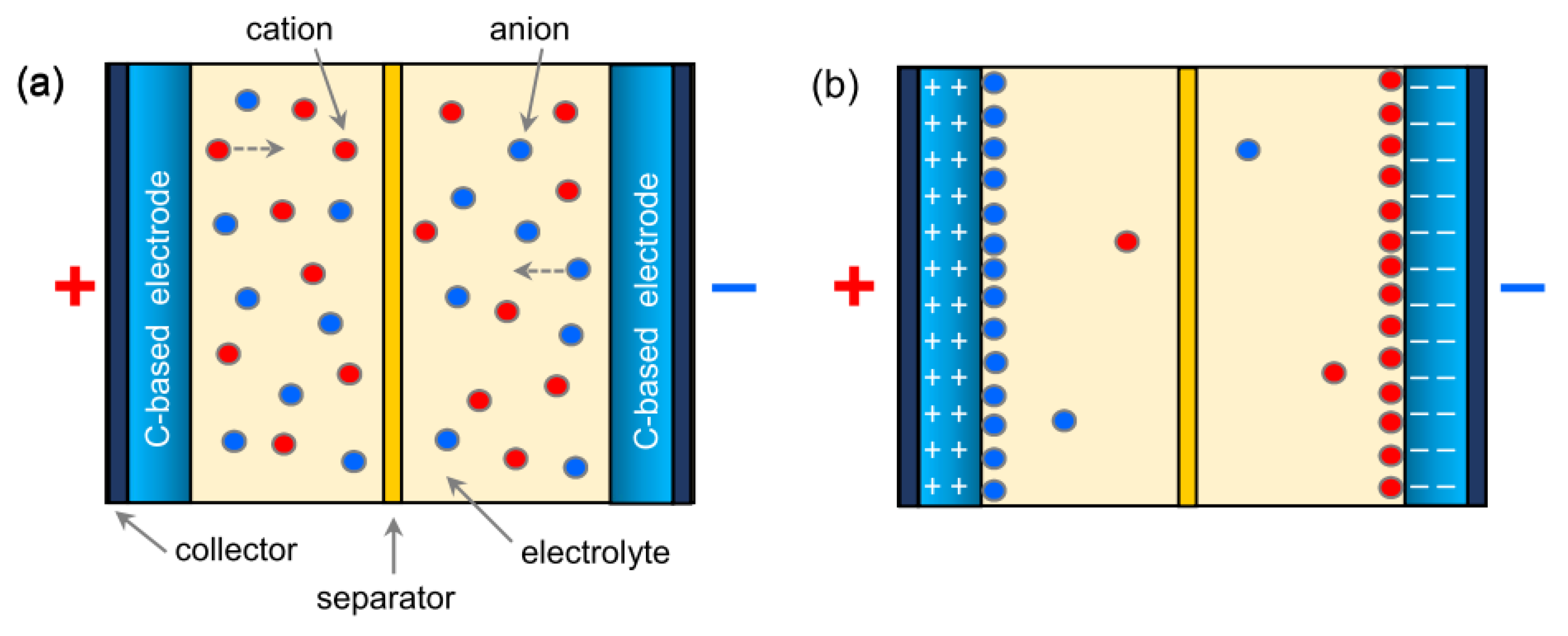
A wide branch of research on energy storage is focused on the electrochemical capacitors [174,175], better known as supercapacitors and also including pseudocapacitors. Supercapacitors and pseudocapacitors differ for the mechanism through which the charge is stored. In the former, the charge storage is based on the fast electrostatic interactions at the electrode surface in contact with the electrolyte (Figure 19)—during the charging process, the ions from the electrolyte are reversibly adsorbed on the high-surface-area electrodes, finally leading to an electrical double layer (EDL). In the latter, fast and reversible redox (Faradaic) processes mainly take place at the surface of the electrodes.
Graphene and other carbonaceous materials show EDL behavior and are featured by high power densities [175]. Transition metal oxides (such as RuO2, MnO2 Fe3O4, V2O5, and Fe3O4 [48,176,177]) show pseudocapacitive behavior and possess high energy density [143]. Hybrid capacitors, consisting of a pseudocapacitive electrode and an EDL electrode, try to efficiently combine the two characteristics.
In spite of the higher specific capacitance generally delivered by materials with pseudocapacitive behavior [48,176,177,178], in recent years, the research efforts are being increasingly focused on sp2-carbon-based materials, which, with their tunable pore structure, abundant surface functionalities, and active defective sites, offer appealing advantages for all applications concerning energy conversion and storage [179] and, in the cases of supercapacitors, also the possibility of fabricating stretchable devices [180].
Since good performance of capacitors with EDL behavior requires appropriate pore size distribution (micro-, meso-, and macro-pores), high electrochemically accessible surface area, and high electrical conductivity [175], porous carbon materials have received great attention. Among them, electrospun carbon fibers, which couple short diffusional paths and flexibility to high conductivity, large aspect ratio, and surface area, represent the most promising candidates.
Table S5 reports some examples of electrode ENMs and their preparation conditions; the main parameters describing their performance are reported in Table S6. PAN [181,182,183,184,185,186,187] or a blend of PAN and PVP [52,53,54,59] is the most frequently utilized polymeric component of the spinnable solution, whereas N,N-dimethylformamide (DMF) commonly acts as a solvent [52,53,54,59,181,182,183,184,185,186,187]. A variety of different additives is employed to generate carbon fibers with specific textural, compositional, or conductive properties [46,47,59,178,182,183,184,185,186,187].
By the use of a blend of PAN and PVP dissolved in DMF, Li et al. [54] have obtained non-woven membranes consisting of porous nitrogen-doped carbon fibers, whose porosity and nitrogen-content can be easily controlled by adjusting the relative-to-PAN PVP content (150–240/100 wt%/wt%) of the solution. As binder-free electrodes, the membranes are able to deliver specific capacitance of 148–198 F/g and exhibit excellent cyclic stability with a retention rate of 104% after 5000 cycles at a rate of 1 A/g [54].
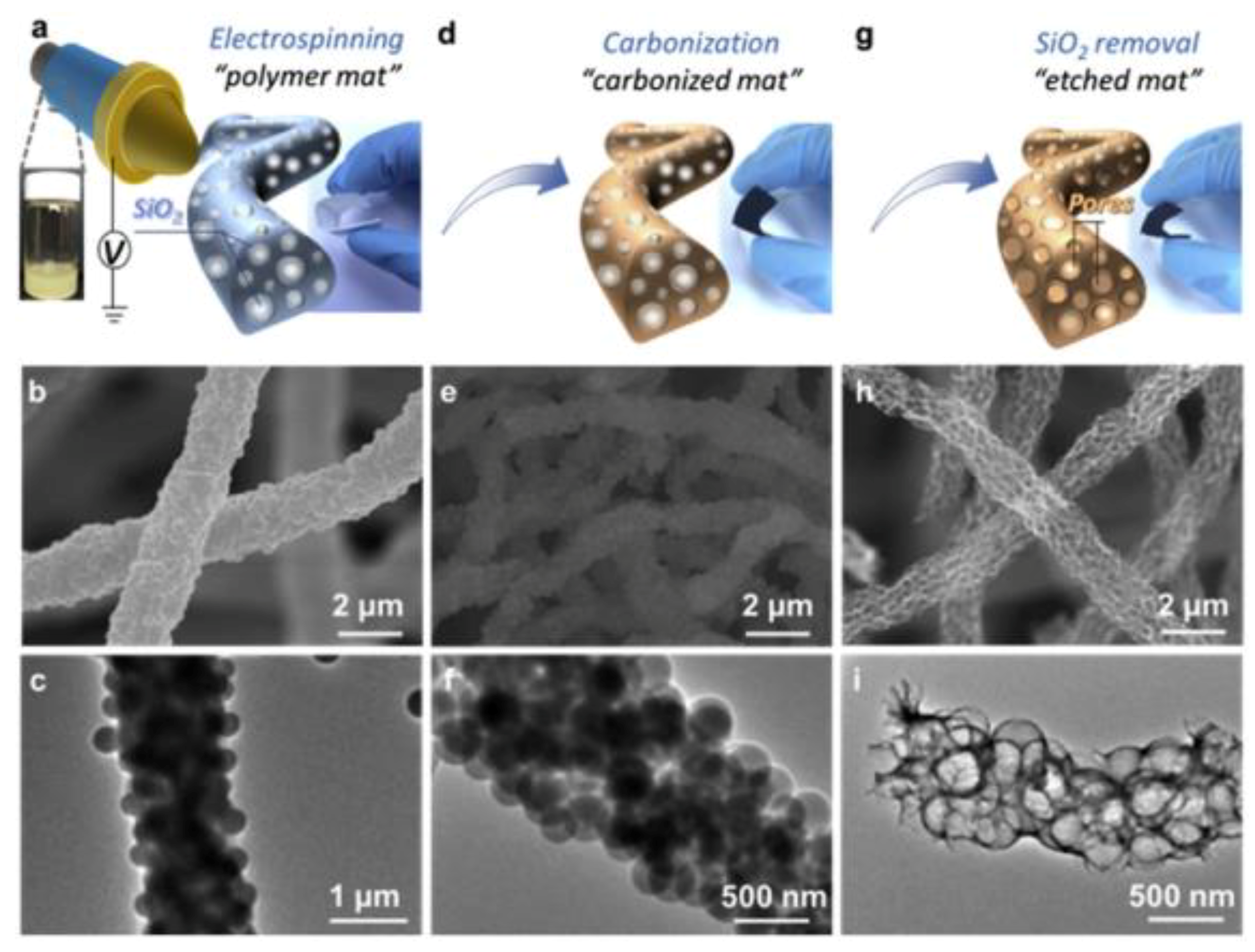
Fan et al. [59] have produced binder-free flexible electrodes for supercapacitors consisting of nitrogen-enriched carbon fiber networks, by adding silica (SiO2) NPs to the spinnable PAN+PVP/DMF solution (Figure 20a–c). SiO2 NPs act as a as a sacrificial templating agent and, after carbonization (Figure 20d–f), are removed by chemical NaOH etching (Figure 20g), finally giving rise to the formation of meso-macroporous fibers with a pretty morphology featured by conjugated surfaces (Figure 20h,i). The specific capacitance delivered by these electrodes is 242 F/g at a rate of 0.2 A/g. They are able to retain 99% of the initial capacitance after 5000 cycles [59].
The size of the electrodes tested in the research works is generally small (their surface area does not usually exceed 1 cm2 [54,59,183,184]). Kim et al. [182] have built supercapacitor cells by assembling two 2.25 cm2 electrodes and, more remarkably, have demonstrated the possibility of depositing an electrospun thin A3-sized (297 mm × 420 mm) fibrous membrane. The addition of (1−5 wt%) zinc chloride to the PAN/DMF solution, enhancing its conductivity, brings about a fiber diameter shrinking during the spinning stage (from 350 to 250 nm). During the subsequent heat treatments (stabilization and carbonization), producing a further fiber thinning, ZnCl2 exerts a catalytic function, accelerating the oxidative stabilization rate and creating micropores on the outer surface of the fibers by etching C atoms [182].
The specific capacitance of the electrodes based on electrospun carbon fibers (Table S6) usually does not exceed 250 F/g [52,53,54,59,181,182,183,184,188]. Various additives, such as graphene nanoplatelets [184], biochar [183], and carbon nanotubes (CNTs) [46,47,185], have been used to improve their performance.
By adding 12 wt% CNTs to the polyaniline/polyethylene oxide (PANI/PEO) spinnable solution, Simotwo et al. [46] have fabricated free-standing, binder-free supercapacitor electrodes by a single-step process requiring no heat treatment. The PANI/CNTs-based electrodes are able to deliver a capacitance of 385 F/g at a current density of 0.5 A/g with a retention capability of 81.4% after 1000 cycles. The three-dimensional electrode structure characteristic of the non-woven interconnected fiber network is responsible for their good electrochemical performance since it facilitates efficient electron conduction, while the inter- and intra-fiber porosity enables excellent electrolyte penetration within the polymer matrix, allowing fast ion transport to the active sites [46].
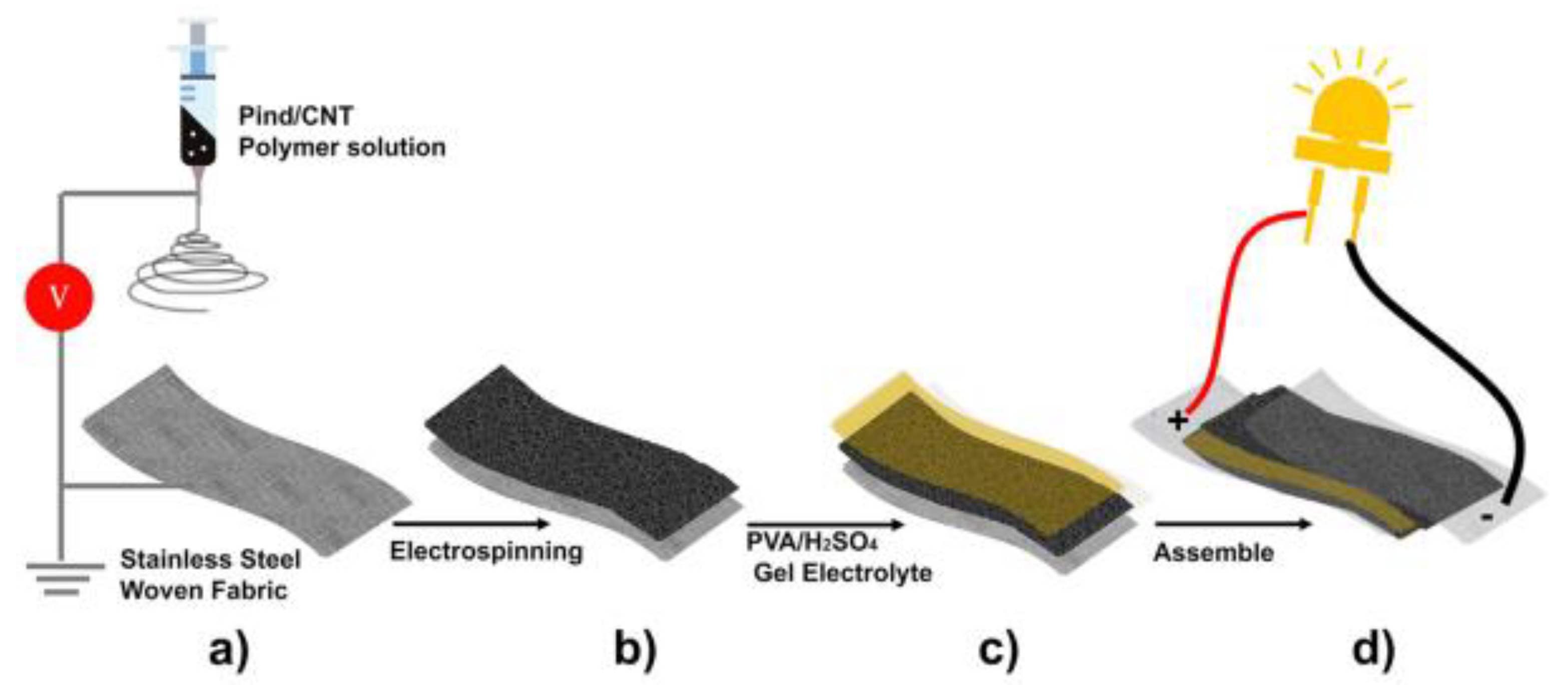
Tebyetekerwa et al. [47] have used a similar single-step process to fabricate self-supporting supercapacitor electrodes by electrospinning a CNT-enriched polyindole-based polymeric solution directly on stainless steel current collectors (Figure 18a,b). The flexible symmetric all-solid-state supercapacitor fabricated by interposing PVA/H2SO4 gel electrolyte between the two so-prepared electrodes (Figure 21c,d) is able to deliver 476 F/g at a current density of 1 A/g, with an excellent retention capability (95% after 2000 cycles) [47].
At the same rate, much higher specific capacitance (1119 F/g) has been obtained by Agyemang et al. [185] by coating CNT-enriched carbon fibers (produced by stabilization and carbonization of as-spun PAN/CNTs fibers under conditions reported in Table S5) with aniline monomer, through in situ chemical polymerization, to form PANI-coated C/CNTs fibers (Figure 22). At very high current density (10 A/g), these composite fibers are still able to deliver 748 F/g. Their high specific capacitance is attributed to the synergic effects of the combination of the high surface area resulting from CNT incorporation, the pseudocapacitive property of PANI, which increases the electrical conductivity, the interaction between the CNT-enriched C fibers and PANI, and the uniform distribution of CNTs within the fibers [185]. PANI-coated C/CNTs fibers are able to retain 98% of the initial capacitance even after 2000 cycles at a current density of 10 A/g [185].
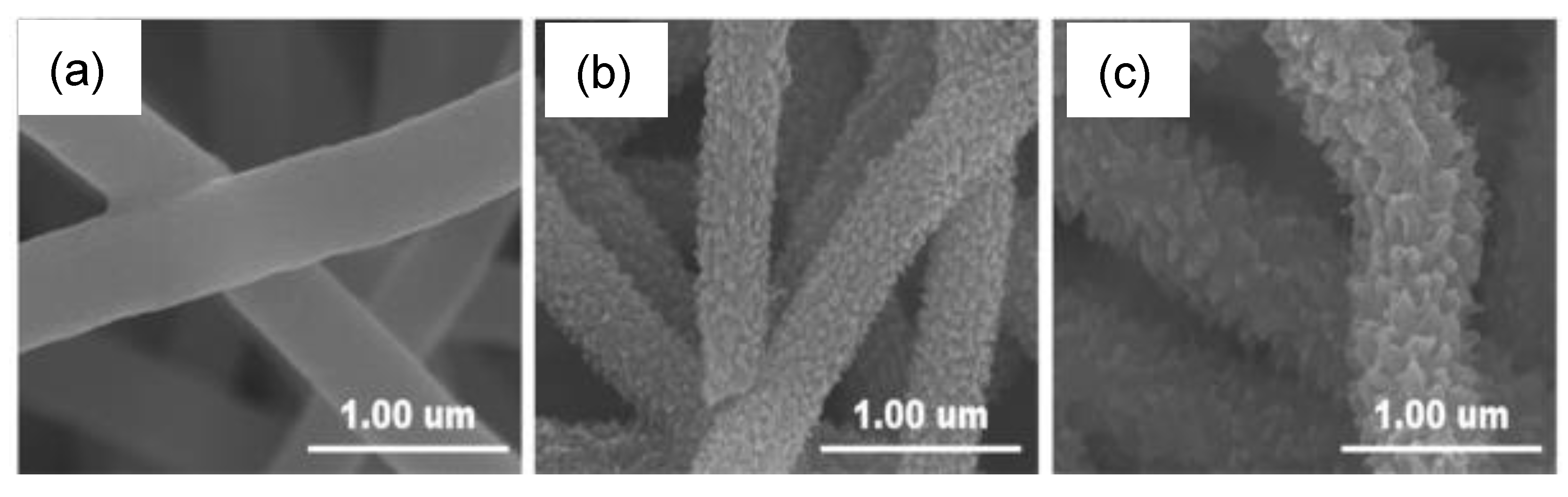
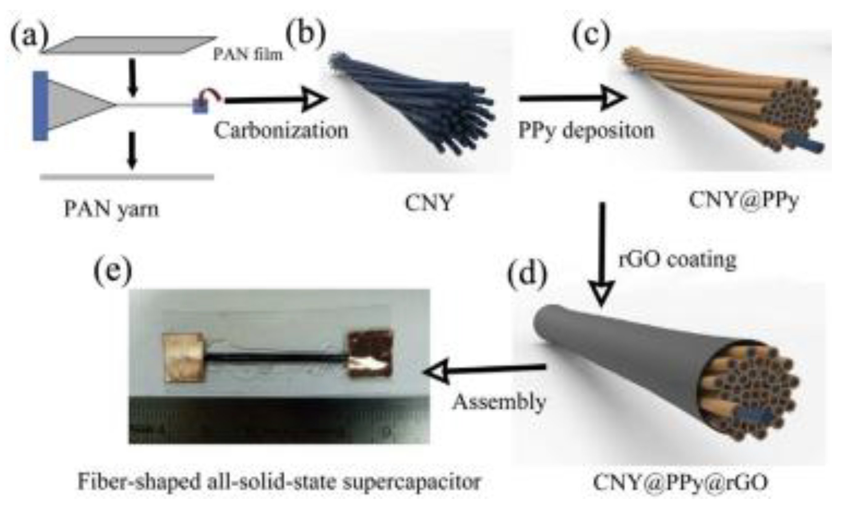
Outstanding stability (86% capacitance retention after 10000 cycles) and excellent flexibility (but associated to much lower specific capacitance values (~93 F/g)) has been reported by Chen et al. [186] for fiber-shaped all-solid-state supercapacitors fabricated, as shown in Figure 23, by using a binder-free carbon nanofibers yarn (CNY) with a core-shell structure (Figure 23e). CNY has been prepared by carbonizing twisted electrospun PAN nanofibers (Figure 23a,b) and subsequently depositing polypyrrole (PPy) on the surface of the CNY (Figure 23c) and reduced graphene oxide (rGO) on the surface of the resulting PPy@CNY (Figure 23d) to finally form a core-shell structure (CNY@PPy@rGO). The high porosity of the flexible CNY results in a large specific surface area for PPy deposition. The deposition of PPy on CNY improves the specific capacitance due to the high pseudocapacitance of PPy, while rGO layer contributes to enhance the electrical conductivity and act as a physical buffering layer. Thanks to the core-shell structure of CNY@PPy@rGO and synergistic effects of the three components, the electrode exhibits a length capacitance of 111.5 mF/cm [186].
7. Capacitive Deionization of Water
The increase in the world population is reflected in a growing demand for fresh water, further boosted by the increasing level of environmental contamination of the commonly exploited aquifer sources. This situation has encouraged the development of the water desalination technologies, and particularly of those addressed to cost-effectiveness and energy-efficiency. Among them, the capacitive deionization (CDI) is one of the most attractive for its simplicity and eco-friendliness, and it has recently received great attention [189,190,191].
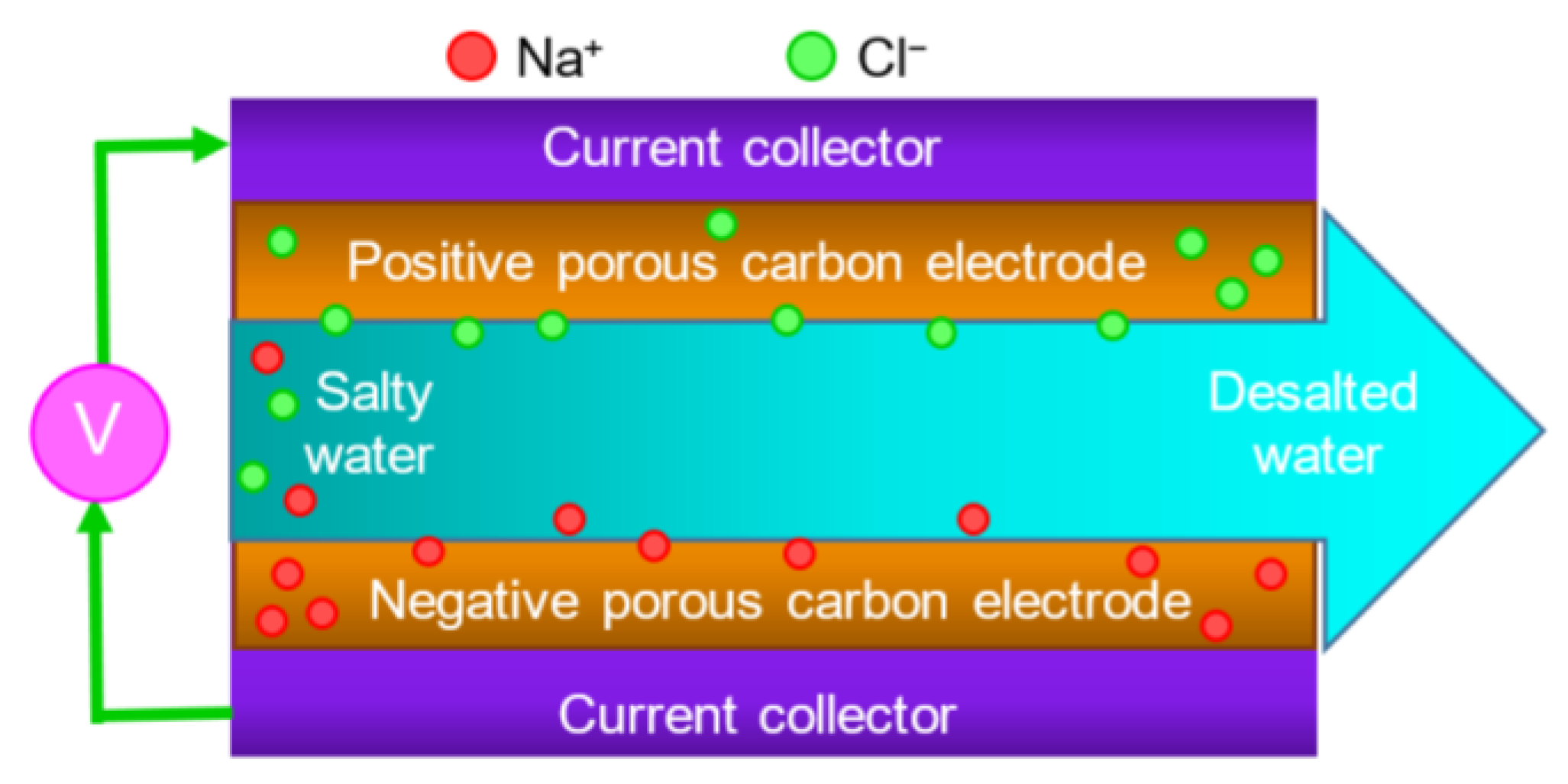
CDI, also known as electrosorptive desalination, is based on the formation of an EDL between the parallel electrodes forming the CDI cell, upon application of a voltage between them [192,193,194,195]. In the presence of the EDL, the Na+ and Cl− ions, present in the salty water inlet into the cell, are reversibly adsorbed onto the porous surface of the negatively and positively charged electrodes, respectively (Figure 24), and the so-obtained desalted water goes out from the cell. During this process, no secondary contaminant is released. Once their surface is saturated by salt ions, the electrodes can be regenerated by reducing/reversing/shorting the cell voltage. This causes the stored ions to be desorbed and released into a wastewater solution.
The low operating voltage of CDI (0.8–1.6 V) can be of great help in remote areas. In addition, the energy required to desalinate one cubic meter of brackish waters by this method is lower than for the reverse osmosis (only 0.1 against 0.2 kWh) [194].
The capacitance of the porous electrode material and, hence, its desalination performance depends on many parameters, including its specific surface area and hydrophilicity, the size and distribution of its pores, as well as its ionic conduction properties [189,191,192,193,194,195]. Based on the electrosorption mechanism and kinetics, porous carbons with good electrical conductivity, hierarchical pore distribution, and high specific surface area are commonly regarded as the optimal materials for the achievement of high CDI performance. A great variety of carbon-based electrode materials, including carbon aerogel [196,197], activated carbons [198], carbon nanotubes [199,200], graphene [201], and graphene-enriched carbonaceous nanostructures [202], have been developed in order to reach this goal. However, some of these materials (e.g., nanotubes) are produced through time-expensive and/or sophisticated processes and have high costs, while others (e.g., activated carbons) involve the use of harsh chemical oxidants, such as KOH or piranha-solution, for activation before their use as CDI electrodes. Electrospinning is a simple and cost-effective technique; moreover, electrospun carbon nanofibers (ECNFs) do not necessarily require activation treatments to exhibit good electrosorptive performance [55].
In the last decade, electrosorption capacities ranging between 1.9 and 6.4 mg/g have been reported for ECNFs and ECNF-based composite materials [203,204,205,206,207,208,209]. In particular, Dong et al. [206] have utilized electrospinning followed by CO2 activation to prepare a hybrid nanomaterial (Figure 25a–c) consisting of CNTs embedded in activated PAN-based carbon fibers (ACF). For this purpose, CNTs have been dispersed in a PAN/DMF solution, and the resulting homogeneous CNT/PAN suspension has been electrospun by the use of the spinning set-up schematized in Figure 25d. After stabilization in air at 280 °C for 2 h, the as-obtained web-like CNT/PAN fibers, have been carbonized in N2 at 800 °C for 2 h and finally activated for 1 h in CO2 at the same temperature, obtaining a composite material (CNT/ACF) with high specific surface area (651 m2/g) and mesopore ratio (64%). The test of the composite nanostructures by means of the setup schematically depicted in Figure 25e has led to a desalination capacity of 6.4 mg/g at an initial NaCl concentration of 400 mg/L and a working potential of 1.2 V. The great improvement (39%) with respect to the CNT-free nanomaterial, prepared and tested under the same conditions, has been ascribed to the increase of conductivity brought about by the incorporation of the high aspect-ratio morphology conductive additive coupled with the high porosity due to the CO2-mediated activation [206].
Indeed, activation by means of different agents is a strategy followed by various groups to enhance the specific surface area of the ECNFs and improve their NaCl removal capacity [203,207,210]. Liu et al. [210] have reported an electrosorption capacity of 10.52 mg/g for PAN-based ECNFs obtained by stabilization in air at 250 °C for 1.5 h, followed by carbonization in N2 at 800 °C for 1 h and activation by means of ZnCl2. Activation consists of impregnation of ECNFs by immersion in a ZnCl2 solution, subsequent heat-treatment in N2 atmosphere at 500 °C, immersion in 1 mol/L hydrochloric acid, and removal of the residual zinc compounds through thorough washing. The consequent increase in specific surface area, micro- and meso-pore volume, and electrode surface wettability by water is thought of as responsible for the relevant improvement in the CDI performance.
Very recently, remarkably higher electrosorption capacities (>15 mg/g at initial NaCl concentrations of 500–600 mg/L) have been reached by the use of graphene-enriched nanohybrids as CDI electrodes [55,211]. Graphene oxide (GO), incorporated at any stage during their preparation and transformed to thermally reduced graphene oxide (TRGO) during carbonization, acts as a bi-dimensional (2D) conductive additive, thus improving the conduction properties of the TRGO-containing hybrid.
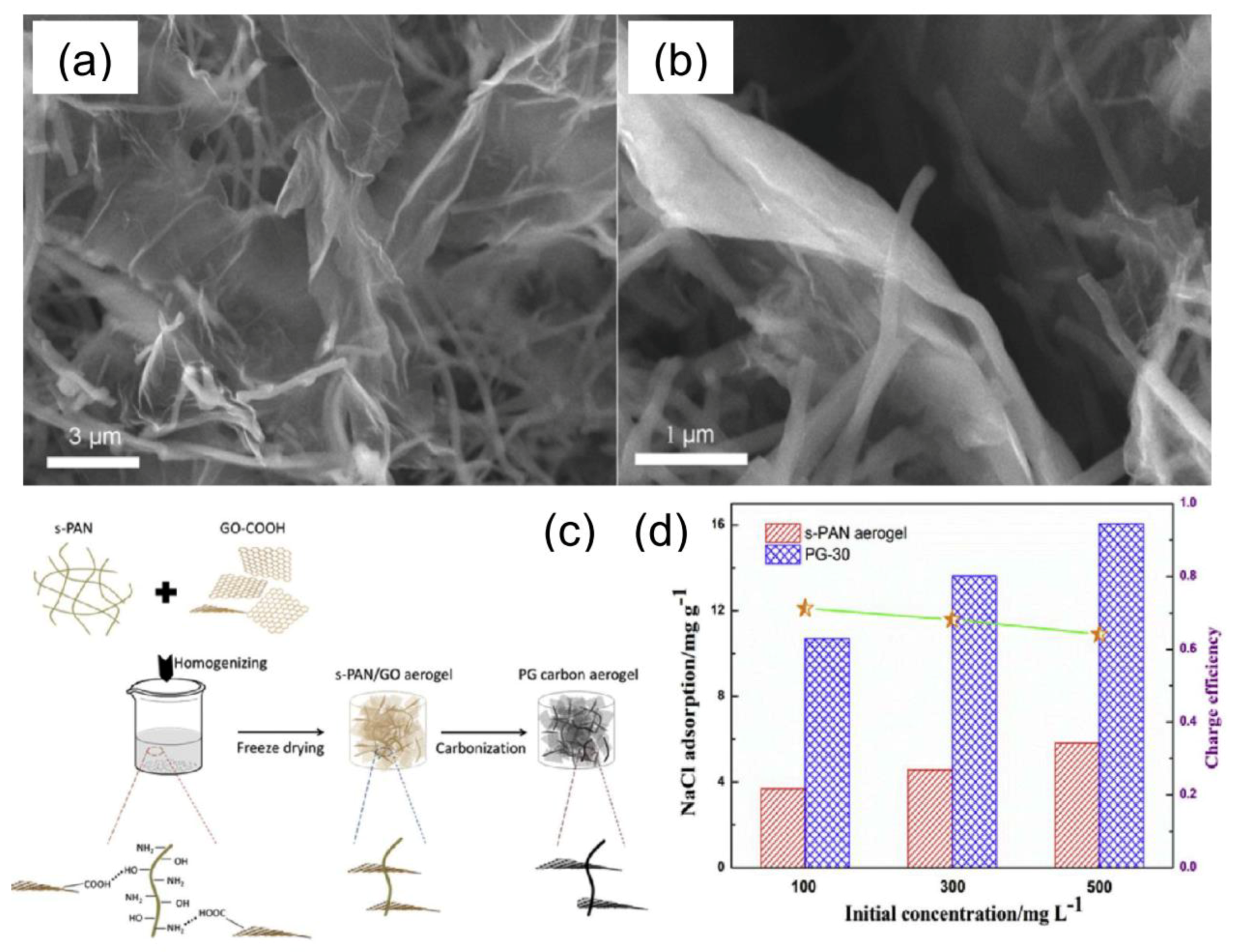
Luo et al. [211] have produced a carbon aerogel with a structure consisting of 1D and 2D carbon nanomaterials, namely ECNFs coupled to graphene (Figure 26a,b), following the three-step procedure sketched in Figure 26c. Briefly, the membrane consisting of PAN-based ECNFs stabilized in air at 250 °C for 2 h (s-PAN), is cut into pieces and, after homogenization in a mixed solvent, is filtered. The resulting short fibers are redispersed, mixed with a GO suspension and homogenized at a very fast rotating speed to assure the sufficient contact and interactions between s-PAN fibers and GO sheets. s-PAN/GO composite aerogel is obtained via freeze-drying of the resulting material, whereas subsequent carbonization at 800 °C in N2 for 2 h of the s-PAN/GO composite aerogel leads to PG carbon aerogel. With respect to the pristine s-PAN/GO composite aerogel, PG carbon aerogel is endowed with higher specific capacitance and remarkably improved electrosorption capacity (Figure 26d). The enhanced electrochemical performance is due to the strong interconnection between the 1D and 2D aerogel components, which favors the electron transfer within the porous structure.
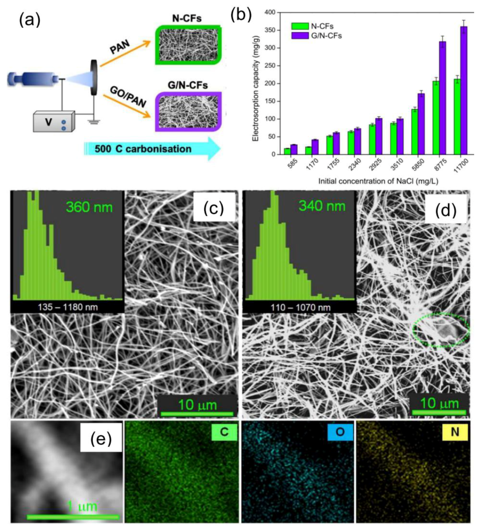
Belaustegui et al. [55] have proposed an unconventional approach to improve the electrochemical performance of ECNFs in water desalination by CDI. As mentioned above, increasing the surface area of the ECNFs via different methods is a commonly followed strategy to improve their salt removal capacity from water. However, as pointed out by Huang et al. [212], the use of extremely high-surface area carbons may be unprofitable since micropores, which contribute to enhancing the material specific surface area, are hardly accessible for the ions and, hence, not active in CDI process. On the other hand, water wettability is known to be very beneficial to the diffusion and adsorption of ions in the solution to the fiber surface and results in improved surface utilization [212]. It is widely recognized that a high N-doping level of the active material is beneficial for the wettability of the electrode surface and pseudo-capacitance, as well [6,195]. Based on these concepts, Belaustegui et al. [55] have demonstrated that ECNFs self-doped with very high nitrogen concentrations (around 20 wt%) are able to remove a relevant amount of NaCl (17.0 mg/g) from a salty solution with an initial concentration of 585 mg/L, and that the electrosorption capacity outstandingly increases (up to 27.6 mg/g) if the N-doped fibers are enriched with graphene (Figure 27). The N-doped ECNFs have been produced (Figure 27a) by choosing a polymer (PAN) with a high N-content (26.4 wt%) and a low carbonization temperature (500 °C). The latter condition results in lower energy consumption and limited release of volatile N-containing by-products, with beneficial effects on the cost-effectiveness, safety, and environmental friendliness of the ECNF production process [55]. Moreover, the superior performance of these fibers with relatively small specific surface areas (17–20 m2/g) with respect to other nanomaterials (e.g., N-doped graphene sponge [201]) featured by smaller N-contents and larger specific surface area demonstrates the crucial role of surface wettability and pore accessibility.
8. Hydrogen Production by Photo-Assisted Electro-Chemical Water Splitting
The need for limiting the effects of using fossil fuels on climate changes and the increasing energy demand associated with the growth of the world population and the enhancement of living standards call for developing clean energy sources. Hydrogen is widely recognized to be a carbon-free, environmentally friendly, renewable, and efficient fuel with high energy density. It has a calorific value nearly three times greater than hydrocarbon fuels. Currently, the production of H2 mainly comes from steam reforming of natural gas [213], consuming natural resources and generating carbon dioxide as an undesired by-product. Solar energy conversion for H2 production via photo-induced water splitting (WS) represents one of the most promising alternative approaches, but presently still contributes to a very small extent (<4%) [213].
The process is schematically depicted in Figure 28. Essentially, photo-electrochemical (PEC) cells act as “artificial photosynthetic devices” that mimic the process of hydrogen production through the light-assisted water splitting occurring in nature [214]. In the cell (Figure 28a), the anode (based on a photoactive n-type semiconductor) is the oxygen-evolving electrode, whereas hydrogen is generated at the cathode, which acts as the counter-electrode [216].
When a light source illuminates the n-type semiconductor acting as photo-anode, the electrons (e−) in the valence band (VB) are excited to the conduction band (CB), and holes (h+) are generated in the VB (Figure 28b). The photo-generated e− and h+ that do not undergo recombination act as the reducing and oxidizing agents, respectively. Electrons participate in the reduction reaction and produce H2, whereas holes carry out oxidation reaction and produce O2 [213].
To achieve an overall WS in hydrogen and oxygen, both the reduction and oxidation potentials of water should lie within the band gap (Eg) of the photo-catalyst. The bottom of the CB must be more negative than the reduction potential of H+/H2 (0 V vs. normal hydrogen electrode, NHE), while the top of the VB must be more positive than the oxidation potential of O2/H2O (1.23 V vs. NHE) [216,217,218].
Figure 29 displays the energy gap (in eV) and band edge positions of some representative semiconductor materials relative to water redox potentials. Only some of them are suitable for overall WS in hydrogen and oxygen. Moreover, since the intensity of the solar spectrum dramatically falls off below 400 nm, to absorb the visible-light irradiation from sunlight, Eg should be lower than 3.1 eV [216].
Titanium dioxide (TiO2) has been the pioneering semiconductor for the photo-catalysis of water [220]. It is environmentally friendly, easily available, cheap, and stable. Nevertheless, absorbing in the near UV region, it can use only an exiguous fraction (5%) of the solar light. In principle, the narrower band gap (2.1–2.3 eV) of hematite enables the absorption of about 40% of the solar spectrum. Thanks to its favorable properties (VB edge lower than the water oxidation potential, chemical stability in a oxidative environment, low cost, and non-toxicity) α-Fe2O3 might represent an attractive alternative to TiO2 for the application in PEC WS on a large scale [214]. However, poor conductivity (of the order of 10−6 S cm−1 for high purity hematite), short hole diffusion length (typically 2–4 nm) and fast electron-hole recombination (10−12 s) at the grain boundaries mainly limit the PEC activity of polycrystalline hematite films.
The design of efficient and stable photo-catalysts for the harvesting of solar energy has become one of the primary challenges in the development of solar H2 economy [221,222]. Many efforts have been made to increase the optical absorption of large-Eg photo-catalysts by varying their chemical composition with metal or non-metal doping or self-impurity [223,224,225]. Also, nano-structuring has allowed obtaining even 1000 h stable photo-anodes [226].
1D-nanostructures, such as nanorods, nanowires, or nanofibers, offer advantages over their bulk counterpart [227]. Besides, minimizing the length scale through which the minority carriers must diffuse and, hence, reducing the probability of recombination losses, 1D-nanostructures may contribute to enhance the photo-conversion efficiency thanks to their higher surface area. In this scenery, the electrospun nanofibres, featured by high porosity, aspect ratio, and surface area, represent very promising candidates for the efficient production of H2 by PEC WS. Table S7 reports some examples of electrospun photo-catalysts and summarizes their preparation conditions. Figure 30 shows the morphology of some of them.
Under UV light irradiation, by the use of electrospun TiO2 nanofibers, hydrogen evolution increases by a factor of ~2.8 with respect to TiO2 prepared by a hydrothermal method, and PEC activity is higher than for reference commercial TiO2 nanoparticles [228]. Lee et al. have reported an H2 evolution rate of 62.7 µmol/h and up to 200 µmol/h by using TiO2/CuO [229] and TiO2/SnO2 (Figure 30a) [230] composite fibers, respectively.
After optimization of the preparation conditions, photo-current densities ranging between 150–200 μA/cm2 and 0.6–1.4 mA/cm2 have been measured for pure and N-doped electrospun TiO2 anodes, respectively [231,232]. Dispersions of the sintered TiO2 fibers produced via ES have been employed to obtain photo-anodes for WS in the form of homogenous films on FTO/glass substrates by the use of doctor-blade, sol-gel dip coating, or by combining the two techniques. In this case, the highest photocurrent density obtained has been 0.5 mA/cm2 [233].
Al-Enizi et al. [234] reported an improvement in the generation of hydrogen gas through the hydrolysis of ammonia borane complex by the use of carbon fibers decorated with Co-TiC nanoparticles-like superficial protrusions (Figure 30b) prepared through a one-step electrospinning approach.
Interesting results have also been obtained by combining electrospinning with different synthesis techniques [235,236]. For instance, under optimized conditions, C-coated TiO2/WO3 fibers prepared by electrospinning combined with hydrothermal method have shown remarkable light absorption in the visible region and enhanced H2-generation rate thanks to the multichannel-improved charge-carrier photosynthetic hetero-junction system with the C layer on the surface of TiO2 as an electron collector and WO3 as a hole collector, leading to effective charge separation on these components [236].
Gao et al. [237] have greatly enhanced the H2 production rate using electrospun TiO2/WO3/Au nanofibers. The enhanced PEC activity of TiO2/WO3/Au with respect to TiO2 and TiO2/WO3 nanofibers has been attributed to the synergistic effect of Schottky and surface plasmon resonance (SPR) due to Au NPs decorating the surface of the composite fibers. In the Z-scheme photosynthetic heterojunction system, WO3 and Au respectively act as h+-collector and e−-collector, promoting effective charge separation, whereas the SPR effect favors the absorption of visible light.
Recently, Saveh-Shemshakia et al. [238] have demonstrated the possibility of fabricating efficient photo-anodes by direct deposition of electrospun hematite fibrous mats over FTO/glass plates. The physicochemical properties of the oxide fibers can be effectively modified by the insertion of elemental impurities in their lattice [51,239,240]. A preliminary study has shown that the doping electrospun of Fe2O3 fibers with aliovalent impurities is a viable route to improve their conductive properties and, hence, their PEC performance [241]. The photocurrents measured in these preliminary experiments (0.94 μA/cm2 and 1.42 μA/cm2 for pure and Si-doped Fe2O3 fibers)—comparable to those reported for hematite films produced by different technique and precursors [242]—are by far below the benchmark for the optimized electrospun hematite photo-anodes (0.5 mA/cm2 [238]). Nonetheless, the nearly threefold increase in the donor concentration (from 1.51∙1019 to 4.35∙1019 cm−3) brought about by doping is responsible for the remarkable enhancement (53%) of photocurrent [241]. In the presence of hole scavengers, such as H2O2, the surface recombination almost disappears, and photocurrent density increases by one order of magnitude (from 1.42 to 15 μA/cm2 at 1.23 V [241]).
Aiming at outlining the larger number of energy-related applications as possible, only the photo-assisted approach to WS has been reviewed here. Of course, also electrospun catalysts able to catalyze the hydrogen and oxygen evolution reactions without the aid of light deserve to be mentioned, as well as ENMs utilized in other technologies for clean energy production, such as fuel cells (see f.i. [243,244,245,246]) and solar cells (see f.i. [247,248,249,250]).
9. Nanogenerators for Energy Harvesting
Energy harvesting is another emerging application field of the ENMs worthy of mention. In recent years, the number of portable or wearable devices available on the electronics market has rapidly multiplied. Owing to the constant enhancement of the living standard of the world population, this trend is not destined to be reversed in the future. Currently, the large majority of these electronic systems uses batteries as external power sources. This implies limited utilization time of the devices and, in second place, great impact on the environment due to the consumption of resources for the battery fabrication and the production of waste at the end of their life cycle. Therefore, besides reducing their weight and size to increase their portability, it is desirable to provide electronic devices with sustainable, self-sufficient power sources to ensure the independence and continuity of their operation.
In recent years, harvesting energy from the surrounding environment (e.g., from acoustic waves, mechanical loads, wind or machine vibrations, human body movements) and converting it into electricity to power these systems has been established as a viable route to provide autonomous portable or wearable electronic devices. This has encouraged the development of various energy-harvesting techniques and micro- and nano-generator technology following the tendency toward the progressive device miniaturization [251]. The majority of energy generators harvest mechanical energy and exploit piezoelectric or triboelectric effect to convert it into electrical energy to supply the self-powered devices into which they are integrated [251,252,253,254].
As schematically illustrated in Figure 31, a non-centrosymmetric crystal structure features piezoelectric materials; lattice distortion produced by the application of stress/strain induces polarization charges, which generate an electrical potential. The transient electron flow driven across the electrode pair applied to the material by this potential can supply low-power electronics. Based on this working mechanism, piezoelectric nanogenerators (PENGs) harvest waste mechanical energy from walking, foot- and finger-tapping, talking, breathing, bending, twisting, and other body movements and transform it to useful electric power [251,255].
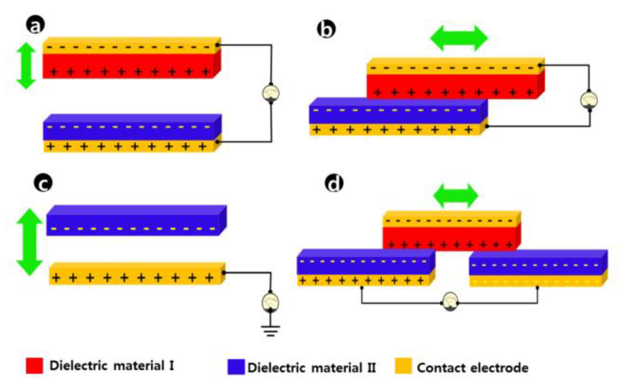
The working mechanism of triboelectric nanogenerators (TENGs) is different. They are based on static electrification induced through frictional contact between different dielectric materials, with the polarity of the induced charge depending on the relative polarity of the two materials [251,256]. Figure 32 sketches the four chief kinds of triboelectric-harvesting device geometry utilized for the fabrication of different types of TENGs [251,256]. A detailed description of their operating modes, device design, and performance enhancement, as well as an accurate illustration of the fundamentals of this technology, can be found elsewhere [252,253,254,256,257,258,259].
Polyvinylidene fluoride (PVDF), a semicrystalline polymer with alternating hydrogen and fluorine units attached to the carbon chain, is one of the most efficient piezoelectric materials [251,255]. It is biocompatible, flexible, chemically resistant, and endowed with high mechanical strength. Its piezoelectricity is due to the electroactive β-phase of the polymer that possesses spontaneous polarization. Electrospun PVDF and PVDF-based composites are extensively utilized in PENGs [251,255,260], since, during electrospinning, the other phases of the polymer can become electroactive (by poling or mechanical stretching) [255]. In addition, with respect to the piezoelectric inorganic semiconductors, PVDF and its copolymers have a greater potential towards flexible and wearable applications because they are lightweight and can be easily processed.
Electrospun PVDF membranes are also utilized in the fabrication of TENGs [261,262,263]. PVDF membranes coated with polydimethylsiloxane to improve their mechanical robustness and optimize their porosity properties have also been employed to manufacture a wearable TENG capable of converting human biomechanical energy into electricity for next-generation wearables [261]. A humidity-resisting TENG, designed to adapt to the environmental humidity caused by human perspiration during sport, has been constructed by the use of PVDF and surface amino-modified cellulose acetate/polyurethane electrospun membranes [262].
Most recently, EESs and energy-harvesting devices have combined into self-charging power systems for wearable and portable electronics of daily use [264]. Sun et al. [265] have designed an ultra-light and flexible self-charging power system entirely based on electrospun paper-like membranes. The system consists of a TENG as an energy harvester and supercapacitors as EESs. The former is arch-shaped and exploits conductive PAN-derived carbon paper as an electrode and nonconductive stabilized-PAN membrane as a triboelectric layer. In the latter, the nonconductive PAN paper acts as a separator, whereas the conductive one is used as a capacitive electrode material.
10. Textiles for Energy Saving through Personal Thermal Management
In the latest years, the need for limiting GHG emissions has greatly boosted the development and utilization of renewable carbon-free energy sources. Cooling and heating systems take up an appreciable fraction of the global energy demand and significantly contribute to enhancing the GHG emissions [266,267]. Hence, another important action against climate changes and extreme weather can be the reduction of these energy consumptions through the improvement of energy efficiency. Taking into consideration the residential and commercial buildings, the principal energy demand originates from indoor cooling and heating. However, a large portion of the energy spent on this purpose is wasted for empty spaces and inanimate objects. For a long time, the approach commonly followed to cope with this problem has consisted of trying to improve the building thermal isolation through the use of innovative materials and suitable design.
In recent years, a new and complementary approach has emerged, intended to profit from the smaller thermal mass of human beings compared with buildings. This approach is centered on providing cooling or heating only in the immediate environment around the human body, to minimize wasted energy and, thus, enhance efficiency [268]. Cui’s group has devoted several efforts in the field of personal thermal management (PTM) [266,267,268,269]. The group has developed wearable textiles with a superior cooling [266,270] or heating effect [269] with respect to common commercially available textiles, able to mitigate the energy demand for outdoor cooling or indoor heating. In particular, Chen et al. [271,272] have utilized the co-axial electrospinning technique to prepare phase-change polyethylene glycol/cellulose acetate (PEG/CA) fibers with great potential in PTM. In the ultrafine composite core-shell fibers, CA and PEG act as a supporting fiber-template material and as a model phase-change material, respectively. The electrospun fibrous material exhibits good thermo-regulating capability. For further information on electrospun phase-change fibers see ref. [8,273].
11. Conclusions
Electrospinning is a very simple, widely accessible, scalable, and cost-effective technique, particularly suitable for the manufacturing of engineered fibrous nanomaterials on an industrial scale. In fact, different from the other synthetic techniques, the production process via electrospinning can proceed continuously, by collecting the as-spun fibers on a suitably designed system using rotating drums. Any thermal treatment needed to modify the fiber physicochemical properties can be operated separately, with no necessity of interrupting the production process. Obviously, this constitutes a singular inherent advantage in view of the large-scale production. Besides, in an industrial context, multi-needle and needleless systems allow facing up to the moderate productivity of the conventional electrospinning.
The outstanding physical and chemical properties of the large variety of intriguing nanostructured materials produced via this fascinating synthetic approach are suitable to the development of a huge number of advanced applications involving the most different fields, exhaustively illustrated in several excellent reviews. The focus of this review is on energy-related applications of the electrospun nanomaterials. In particular, the recent advances produced by their use in secondary alkali metal-ion batteries, redox flow batteries, metal-air batteries, supercapacitors, reactors for water desalination via capacitive deionization, hydrogen production by solar-driven water splitting, nanogenerators for energy harvesting, and textiles for energy-saving personal thermal management are reviewed, trying to report aspects believed to be of importance to attract the interest and stimulate the inventiveness of the readers.
Even if outstanding results have been achieved, many are the challenges still to be faced, bearing in mind the ultimate goal of pushing electrospun nanomaterials from the laboratory to industry. For instance, although doping with aliovalent elements has enhanced their conductive properties, the mechanical strength of ceramic nanofibers needs to be improved, and solutions for the production of flexible mats for their use as free-standing electrodes have still to be found. In the case of carbonaceous fibrous membranes, despite the progress recently made, the tendency towards the aggregation of the dispersed very small-sized nanoparticles responsible for the electrode instability still needs attention. Besides, the lack of full control of their pore size and distribution hinders from having carbon fibers with finely tunable porosity and hierarchical porosity, thus limiting the performance of all applications benefiting from them. A similar necessity concerns fiber diameter and mechanical robustness, as well as orientation. Another absolutely non-negligible aspect is represented by the impact on human health and the environment. The solvent (N,N-dimethylformamide) utilized to disperse the polymers (polyacrylonitrile and polyvinyl pyrrolidone) most frequently selected for the fabrication of carbon-, carbon-based, and ceramic fibers are not free of toxic effects.
In light of these considerations, some future research directions in the field of energy-related applications of electrospun nanomaterials could be:
- Search for safer polymer/solvent combinations and abundant, non-toxic precursors to limit the impact of the fiber production on human health as well as the environment.
- Development of ceramic fibers with improved mechanical strength for the production of flexible mats to be used as free-standing electrodes.
- For the composite fibers, improvement of the existing approaches to contrast the tendency towards the aggregation of the very small-sized nanoparticles embedded into the carbon matrix.
- Search for new additives and development of new fiber surface-modification methods to generate electrospun nanomaterials endowed with new functionalities.
- Introduction of new methodologies for the full control of the fiber diameter to be able to produce ultrathin fibers, as well as of the fiber pore size and distribution to enable the fine tunability of their (even hierarchical) porosity.
- Design of new (e.g., suitably patterned) collectors to realize fibrous mats endowed with specific shapes and fiber orientations.
- Invention of new spinning geometries allowing for the integration of different functionalities in a single-layered multi-component fibrous mat.
For sure, all the challenging open questions will motivate the scientific community, leading them to make significant breakthroughs in the future. This will permit the move beyond the current state of the electrospun nanomaterial technology, towards their commercialization and penetration in daily life.
Supplementary Materials
The following are available online at https://www.mdpi.com/2076-3417/9/6/1049/s1, Table S1: ENMs for SIB cathodes and preparation conditions; Table S2: Main parameters describing the performance of cathode ENMs in SIBs; Table S3: ENMs for SIB anodes and preparation conditions; Table S4: Main parameters describing the performance of cathode ENMs in SIBs; Table S5: Electrode ENMs for supercapacitors and preparation conditions; Table S6: Main parameters describing the performance of electrode ENMs in supercapacitors; Table S7: Electrospun photo-catalysts for WS and preparation conditions.
Funding
From the Italian Ministry of Education, University and Research (MIUR) through the project “Towards sustainable, high-performing, all-solid-state sodium-ion” (PRIN 2017MCEEY4) and from MDPI for the publication in open access.
Acknowledgments
The author gratefully thanks MIUR for the financial support to research and MDPI for funding the publication in open access, as well as all colleagues working with her at Lab. of Materials for Environmental & Energetic Sustainability (MatEES) of Mediterranean University of Reggio Calabria.
Conflicts of Interest
The author declares no conflict of interest.
References
- Cho, H.; Min, S.Y.; Lee, T.W. Electrospun organic nanofiber electronics and photonics. Macromol. Mater. Eng. 2013, 298, 475–486. [Google Scholar] [CrossRef]
- Fang, J.; Shao, H.; Niu, H.; Lin, T. Applications of electrospun nanofibers for electronic devices. In Handbook of Smart Textiles; Tao, X., Ed.; Springer: Singapore, 2015; pp. 617–652. [Google Scholar] [CrossRef]
- Xue, J.; Xie, J.; Liu, W.; Xia, Y. Electrospun nanofibers: New concepts, materials, and applications. Acc. Chem. Res. 2017, 50, 1976–1987. [Google Scholar] [CrossRef]
- Lim, C.T. Nanofiber technology: Current status and emerging developments. Prog. Polym. Sci. 2017, 70, 1–17. [Google Scholar] [CrossRef]
- Thenmozhi, S.; Dharmaraj, N.; Kadirvelu, K.; Kim, H.Y. Electrospun nanofibers: New generation materials for advanced applications. Mater. Sci. Eng. B 2017, 217, 36–48. [Google Scholar] [CrossRef]
- Ghafoor, B.; Aleem, A.; Ali, M.N.; Mir, M. Review of the fabrication techniques and applications of polymeric electrospun nanofibers for drug delivery systems. J. Drug Deliv. Sci. Technol. 2018, 48, 82–87. [Google Scholar] [CrossRef]
- Esfahani, M.R.; Aktij, S.A.; Dabaghian, Z.; Firouzjaei, M.D.; Rahimpour, A.; Eke, J.; Esboar, I.C.; Abolhassani, M.; Greenlee, L.F.; Esfahani, A.R.; et al. Nanocomposite membranes for water separation and purification: Fabrication, modification, and applications. Separ. Purific. Technol. 2018, 213, 465–499. [Google Scholar] [CrossRef]
- Wu, Y.; Chen, C.; Jia, Y.; Wu, J.; Huang, Y.; Wang, L. Review on electrospun ultrafine phase change fibers (PCFs) for thermal energy storage. Appl. Energy 2018, 210, 167–181. [Google Scholar] [CrossRef]
- Ding, J.; Zhang, J.; Li, J.; Li, D.; Xiao, C.; Xiao, H.; Yang, H.; Zhuang, X.; Chen, X. Electrospun polymer biomaterials. Prog. Polym. Sci. 2019. [Google Scholar] [CrossRef]
- Jung, J.W.; Lee, C.L.; Yu, S.; Kim, I.D. Electrospun nanofibers as a platform for advanced secondary batteries: A comprehensive review. J. Mater. Chem. A 2016, 4, 703–751. [Google Scholar] [CrossRef]
- Cavaliere, S.; Subianto, S.; Savych, I.; Jones, D.J.; Roziere, J. Electrospinning: Designed architectures for energy conversion and storage devices. Energy Environ. Sci. 2011, 4, 4761–4786. [Google Scholar] [CrossRef]
- Zhang, X.; Ji, L.; Toprakci, O.; Liang, Y.; Alcoutlabi, M. Electrospun Nanofiber-based anodes, cathodes, and separators for advanced lithium-ion batteries. Polym. Rev. 2011, 51, 239–264. [Google Scholar] [CrossRef]
- Mao, X.; Hatton, T.A.; Rutledge, G.C. A review of Electrospun Carbon Fibers as Electrode Materials for Energy Storage. Curr. Org. Chem. 2013, 17, 1390–1401. [Google Scholar] [CrossRef]
- Pampal, E.S.; Stojanovska, E.; Simon, B.; Kilic, A. A Review of nanofibrous structures in lithium ion batteries. J. Power Sources 2015, 300, 199–215. [Google Scholar] [CrossRef]
- Aravindan, V.; Sundaramurthy, J.; Kumar, P.S.; Lee, Y.S.; Ramakrishna, S.; Madhavi, S. Electrospun nanofibers: A prospective electro-active material for constructing high performance Li-ion batteries. Chem. Commun. 2015, 51, 2225–2235. [Google Scholar] [CrossRef]
- Li, X.; Chen, Y.; Huang, H.; Mai, Y.W.; Zhou, L. Electrospun carbon-based nanostructured electrodes for advanced energy storage—A review. Energy Storage Mater. 2016, 5, 58–92. [Google Scholar] [CrossRef]
- Armer, C.F.; Yeoh, J.S.; Li, X.; Lowe, A. Electrospun vanadium-based oxides as electrode materials. J. Power Sources 2018, 395, 414–429. [Google Scholar] [CrossRef]
- Li, L.; Peng, S.; Lee, J.K.Y.; Ji, D.; Srinivasan, M.; Ramakrishna, S. Electrospun hollow nanofibers for advanced secondary batteries. Nano Energy 2017, 39, 111–139. [Google Scholar] [CrossRef]
- Cooley, J.F. Apparatus for Electrically Dispersing Fluids. U.S. Patent 692631, 4 February 1902. [Google Scholar]
- Morton, W.J. Method of Dispersing Fluid. U.S. Patent 705691, 29 July 1902. [Google Scholar]
- Formhals, A.; Gastell, S.R. Process and apparatus for preparing artificial threads. U.S. Patent 1975504, 2 October 1934. [Google Scholar]
- Formhals, A. Electrical Spinning of Fibers from Solutions. U.S. Patent 2123992, 19 July 1938. [Google Scholar]
- Formhals, A. Electrical Spinning of Fibers Such as Those Produced from Cellulose Acetate. U.S. Patent 2116942, 19 July 1938. [Google Scholar]
- Formhals, Production of Artificial Fibers. U.S. Patent 2077373, 1 April 1937.
- Formhals, A. Method and Apparatus for Spinning. U.S. Patent 2160962, 1 July 1939. [Google Scholar]
- Formhals, A. Artificial Thread and Method of Producing Same Field. U.S. Patent 2187306, 16 January 1940. [Google Scholar]
- Formhals, A. Producing of Artifical Fibres from Fibre Forming Liquids. U.S. Patent 2323025, 29 January 1943. [Google Scholar]
- Formhals, A. Method and Apparatus for Spinning. U.S. Patent 2349950, 30 May 1944. [Google Scholar]
- Zeleny, J. The electrical discharge from liquid points, and a hydrostatic method of measuring the electric intensity at their surfaces. Phys. Rev. 1914, 3, 69. [Google Scholar] [CrossRef]
- Taylor, G.I. Disintegration of water droplets in an electric field. Proc. R. Soc. Lond. A 1964, 280, 383–397. [Google Scholar] [CrossRef]
- Taylor, G.I.; Van Dyke, M.D. The force exerted by an electric field on a long cylindrical conductor. Proc. R. Soc. Lond. A 1966, 291, 145–158. [Google Scholar] [CrossRef]
- Taylor, G.I.; Van Dyke, M.D. Electrically driven jets. Proc. R. Soc. Lond. A 1969, 313, 453–475. [Google Scholar] [CrossRef]
- Baumgarten, P.K. Electrostatic spinning of acrylic microfibers. J. Colloid Interf. Sci. 1971, 36, 71–79. [Google Scholar] [CrossRef]
- Fong, H.; Chun, I.; Reneker, D. Beaded nanofibers formed during electrospinning. Polymer 1999, 40, 4585–4592. [Google Scholar] [CrossRef]
- Doshi, J.; Reneker, D.H. Electrospinning process and applications of electrospun fibers. J. Electrost. 1995, 35, 151–160. [Google Scholar] [CrossRef]
- Reneker, D.H.; Chun, I. Nanometre diameter fibres of polymer, produced by electrospinning. Nanotechnology 1996, 7, 216. [Google Scholar] [CrossRef]
- Reneker, D.H.; Yarin, A.L.; Fong, H.; Koombhongse, S. Bending instability of electrically charged liquid jets of polymer solutions in electrospinning. J. Appl. Phys. 2000, 87, 4531–4547. [Google Scholar] [CrossRef]
- Koombhongse, S.; Liu, W.; Reneker, D.H. Flat polymer ribbons and other shapes by electrospinning. J. Polym. Sci. B 2001, 39, 2598–2606. [Google Scholar] [CrossRef] [Green Version]
- Yarin, A.L.; Koombhongse, S.; Reneker, D.H. Bending instability in Electrospinning of nanofibers. J. Appl. Phys. 2001, 89, 3018–3026. [Google Scholar] [CrossRef]
- Hohman, M.M.; Shin, M.; Rutledge, G.; Brenner, M.P. Electrospinning and electrically forced jets. I. Stability theory. Phys. Fluids 2001, 13, 2201–2220. [Google Scholar] [CrossRef]
- Hohman, M.M.; Shin, M.; Rutledge, G.; Brenner, M.P. Electrospinning and electrically forced jets. II. Applications. Phys. Fluids 2001, 13, 2221–2236. [Google Scholar] [CrossRef]
- Shin, Y.M.; Hohman, M.M.; Brenner, M.P.; Rutledge, G.C. Experimental characterization of electrospinning: The electrically forced jet and instabilities. Polymer 2001, 42, 09955–09967. [Google Scholar] [CrossRef]
- Shin, Y.M.; Hohman, M.M.; Brenner, M.P.; Rutledge, G.C. Electrospinning: A whipping fluid jet generates submicron polymer fibers. Appl. Phys. Lett. 2001, 78, 1149–1151. [Google Scholar] [CrossRef]
- Fridrikh, S.V.; Yu, J.H.; Brenner, M.P.; Rutledge, G.C. Controlling the fiber diameter during electrospinning. Phys. Rev. Lett. 2003, 90, 144502. [Google Scholar] [CrossRef]
- Liu, Q.; Zhu, J.; Zhang, L.; Qiu, Y. Recent advances in energy materials by electrospinning. Renew. Sustain. Energy Rev. 2018, 81, 1825–1858. [Google Scholar] [CrossRef]
- Simotwo, S.K.; Del Re, C.; Kalra, V. Supercapacitor Electrodes Based on High-Purity Electrospun Polyaniline and Polyaniline–Carbon Nanotube Nanofibers. ACS Appl. Mater. Interfaces 2016, 8, 21261–21269. [Google Scholar] [CrossRef]
- Tebyetekerwa, M.; Yang, S.; Peng, S.; Xu, Z.; Shao, W.; Pan, D.; Ramakrishna, S.; Zhu, M. Unveiling polyindole: Freestanding as-electrospun polyindole nanofibers and polyindole/carbon nanotubes composites as enhanced electrodes for flexible all-solid-state supercapacitors. Electrochim. Acta 2017, 247, 400–409. [Google Scholar] [CrossRef]
- Wee, G.; Soh, H.Z.; Cheah, Y.L.; Mhaisalkar, S.G.; Srinivasan, M. Synthesis and electrochemical properties of electrospun V2O5 nanofibers as supercapacitor electrodes. J. Mater. Chem. 2010, 20, 6720–6725. [Google Scholar] [CrossRef]
- Faggio, G.; Modafferi, V.; Panzera, G.; Alfieri, D.; Santangelo, S. Micro-Raman and photoluminescence analysis of composite vanadium oxide/poly-vinyl acetate fibres synthesized by electrospinning. J. Raman Spectr. 2012, 43, 761–768. [Google Scholar] [CrossRef]
- Leonardi, S.G.; Mirzaei, A.; Bonavita, A.; Santangelo, S.; Frontera, P.; Pantò, F.; Antonucci, P.L.; Neri, G. A comparison of ethanol sensing properties of α-iron oxide nanostructures prepared via sol-gel and electrospinning technics. Nanotechnology 2016, 27, 75502–75511. [Google Scholar] [CrossRef]
- Santangelo, S.; Patanè, S.; Frontera, P.; Pantò, F.; Triolo, C.; Stelitano, S.; Antonucci, P.L. Effect of calcium- and/or aluminum-incorporation on morphological, structural and photoluminescence properties of electro-spun zinc oxide fibers. Mater. Res. Bull. 2017, 92, 9–18. [Google Scholar] [CrossRef]
- He, T.; Fu, Y.; Meng, X.; Yu, X.; Wang, X. A novel strategy for the high performance supercapacitor based on polyacrylonitrile-derived porous nanofibers as electrode and separator in ionic liquid electrolyte. Electrochim. Acta 2018, 282, 97–104. [Google Scholar] [CrossRef]
- Niu, H.; Zhang, J.; Xie, Z.; Wang, X.; Lin, T. Preparation, structure and supercapacitance of bonded carbon nanofiber electrode materials. Carbon 2011, 49, 2380–2388. [Google Scholar] [CrossRef]
- Li, X.; Zhao, Y.; Bai, Y.; Zhao, X.; Wang, R.; Huang, Y.; Liang, Q.; Huang, Z. A non-woven network of porous nitrogen-doping carbon nanofibers as a binder-free electrode for supercapacitors. Electrochim. Acta 2017, 230, 445–453. [Google Scholar] [CrossRef]
- Belaustegui, Y.; Zorita, S.; Fernández-Carretero, F.; García-Luis, A.; Pantò, F.; Stelitano, S.; Frontera, P.; Antonucci, P.; Santangelo, S. Electrospun graphene-enriched nitrogen-doped carbon fibres for electrochemical water desalination. Desalination 2018, 428, 40–49. [Google Scholar] [CrossRef]
- Pantò, F.; Fan, Y.; Frontera, P.; Stelitano, S.; Fazio, E.; Patanè, S.; Marelli, M.; Antonucci, P.L.; Neri, F.; Pinna, N.; et al. Are electrospun carbon/metal oxide composite fibres relevant electrode materials for Li-ion batteries? J. Electrochem. Soc. 2016, 163, A2930–A2937. [Google Scholar] [CrossRef]
- Pantò, F.; Fan, Y.; Stelitano, S.; Fazio, E.; Frontera, P.; Patanè, S.; Antonucci, P.L.; Pinna, N.; Santangelo, S. Electrospun C/GeO2 paper-like electrodes for flexible Li-ion batteries. Int. J. Hydrog. Energy 2017, 42, 28102–28112. [Google Scholar] [CrossRef]
- Pantò, F.; Fan, Y.; Stelitano, S.; Fazio, E.; Frontera, P.; Patanè, S.; Antonucci, P.L.; Pinna, N.; Santangelo, S. Are electro-spun fibrous membranes relevant electrode materials for Li-ion batteries? The case of the composite C/GeO2 fibres. Adv. Funct. Mater. 2018, 28, 1800938–1800951. [Google Scholar] [CrossRef]
- Fan, L.; Yang, L.; Ni, X.; Han, J.; Guo, R.; Zhang, C.J. Nitrogen-enriched meso-macroporous carbon fiber network as a binder-free flexible electrode for supercapacitors. Carbon 2016, 107, 629–637. [Google Scholar] [CrossRef]
- Yang, Z.; Zhang, J.; Kintner-Meyer, M.C.; Lu, X.; Choi, D.; Lemmon, J.P.; Liu, J. Electrochemical energy storage for green grid. Chem. Rev. 2011, 111, 3577–3613. [Google Scholar] [CrossRef]
- Office of Electricity Delivery and Energy Reliability—United States Department of Energy (DOE), Global Energy Storage Database. 2018. Available online: www.energystorageexange.org (accessed on 1 December 2018).
- Linden, D.; Reddy, T.B. Handbook of Batteries; McGraw-Hill: New York, NY, USA, 2002. [Google Scholar]
- Thackeray, M.M.; David, W.I.F.; Bruce, P.G.; Goodenough, J.B. Lithium insertion into manganese spinels. Mater. Res. Bull. 1983, 18, 461–472. [Google Scholar] [CrossRef]
- Ritchie, A.G.; Giwa, C.O.; Lee, J.C.; Bowles, P.; Gilmour, A.; Allan, J.; Rice, D.A.; Brady, F.; Tsang, S.C.E. Future cathode materials for lithium rechargeable batteries. J. Power Sources 1999, 80, 98–102. [Google Scholar] [CrossRef]
- Wang, Y.; Yan, F.; Liu, S.W.; Tan, A.Y.S.; Song, H.; Sun, X.W.; Yang, H.Y. Onion-like carbon matrix supported Co3O4 nanocomposites: A highly reversible anode material for lithium ion batteries with excellent cycling stability. J. Mater. Chem. A 2013, 1, 5212–5216. [Google Scholar] [CrossRef]
- Zhang, M.; Uchaker, E.; Hu, S.; Zhang, Q.; Wang, T.; Cao, G.; Li, J. CoO-carbon nanofiber networks prepared by electrospinning as binder-free anode materials for lithium-ion batteries with enhanced properties. Nanoscale 2013, 5, 12342–12349. [Google Scholar] [CrossRef] [PubMed]
- Zhang, X.; Liu, H.; Petnikota, S.; Ramakrishna, S.; Fan, H.J. Electrospun Fe2O3-carbon composite nanofibers as durable anode materials for lithium ion batteries. J. Mater. Chem. A 2014, 2, 10835–10841. [Google Scholar] [CrossRef]
- Wang, H.G.; Zhou, Y.; Shen, Y.; Li, Y.; Zuo, Q.; Duan, Q. Fabrication, formation mechanism and the application in lithium-ion battery of porous Fe2O3 nanotubes via single-spinneret electrospinning. Electrochim. Acta 2015, 158, 105–112. [Google Scholar] [CrossRef]
- Chan, C.K.; Peng, H.; Liu, G.; McIlwrath, K.; Zhang, X.F.; Huggins, R.A.; Cui, Y. High-performance lithium battery anodes using silicon nanowires. Nat. Nanotechnol. 2008, 3, 31–35. [Google Scholar] [CrossRef]
- Xu, Y.; Zhu, Y.; Liu, Y.; Wang, C. Electrochemical performance of porous carbon/tin composite anodes for sodium-ion and lithium-ion batteries. Adv. Energy Mater. 2013, 3, 128–133. [Google Scholar] [CrossRef]
- Hu, Z.; Zhang, S.; Zhang, C.; Cui, G. High performance germanium-based anode materials. Coord. Chem. Rev. 2016, 326, 34–85. [Google Scholar] [CrossRef]
- Ngo, D.T.; Le, H.T.T.; Kalubarme, R.S.; Lee, J.Y.; Park, C.N.; Park, C.J. Uniform GeO2 dispersed in nitrogen-doped porous carbon core–shell architecture: An anode material for lithium ion batteries. J. Mater. Chem. A 2015, 3, 21722–21732. [Google Scholar] [CrossRef]
- Li, M.; Zhou, D.; Song, W.L.; Li, X.; Fan, L.Z. Highly stable GeOx@C core–shell fibrous anodes for improved capacity in lithium-ion batteries. J. Mater. Chem. A 2015, 3, 19907–19912. [Google Scholar] [CrossRef]
- Lee, Y.W.; Kim, D.M.; Kim, S.J.; Kim, M.C.; Choe, H.S.; Lee, K.H.; Sohn, J.I.; Cha, S.N.; Kim, J.M.; Park, K.W. In situ synthesis and characterization of Ge embedded electrospun carbon nanostructures as high performance anode material for lithium-ion batteries. ACS Appl. Mater. Interfaces 2016, 8, 7022–7029. [Google Scholar] [CrossRef] [PubMed]
- Fergus, J.W. Recent developments in cathode materials for lithium ion batteries. J. Power Sources 2010, 195, 939–954. [Google Scholar] [CrossRef]
- Zhu, N.; Liu, W.; Xue, M.; Xie, Z.; Zhao, D.; Zhang, M.; Chen, J.; Cao, T. Graphene as a conductive additive to enhance the high-rate capabilities of electrospun Li4Ti5O12 for lithium-ion batteries. Electrochim. Acta 2010, 55, 5813–5818. [Google Scholar] [CrossRef]
- Li, W.; Yang, Z.; Cheng, J.; Zhong, X.; Gu, L.; Yu, Y. Germanium nanoparticles encapsulated in flexible carbon nanofibers as self-supported electrodes for high performance lithium-ion batteries. Nanoscale 2014, 6, 4532–4537. [Google Scholar] [CrossRef] [PubMed]
- Dufficy, M.K.; Khan, S.A.; Fedkiw, P.S. Hierarchical graphene-containing carbon nanofibers for lithium-ion battery anodes. ACS Appl. Mater. Interfaces 2016, 8, 1327–1336. [Google Scholar] [CrossRef] [PubMed]
- Zhu, Y.; Fan, X.; Suo, L.; Luo, C.; Gao, T.; Wang, C. Electrospun FeS2@carbon fiber electrode as a high energy density cathode for rechargeable lithium batteries. ACS Nano 2016, 10, 1529–1538. [Google Scholar] [CrossRef] [PubMed]
- Zhao, F.; Zhao, X.; Peng, B.; Gan, F.; Yao, M.; Tan, W.; Dong, J.; Zhang, Q. Polyimide-derived carbon nanofiber membranes as anodes for high-performance flexible lithium ion batteries. Chin. Chem. Lett. 2018, 29, 1692–1697. [Google Scholar] [CrossRef]
- Liu, X.; Jiang, Y.; Li, K.; Xu, F.; Zhang, P.; Ding, Y. Electrospun free-standing N-doped C@SnO2 anode paper for flexible Li-ion batteries. Mater. Res. Bull. 2019, 109, 41–48. [Google Scholar] [CrossRef]
- Xu, Y.; Yuan, T.; Bian, Z.; Sun, H.; Pang, Y.; Peng, C.; Yang, J.; Zheng, S. Electrospun flexible Si/C@CNF nonwoven anode for high capacity and durable lithium-ion battery. Compos. Commun. 2019, 11, 1–5. [Google Scholar] [CrossRef]
- Kim, J.K.; Manuel, J.; Lee, M.H.; Scheers, J.; Lim, D.H.; Johansson, P.; Ahn, J.H.; Matic, A.; Jacobsson, P. Towards flexible secondary lithium batteries: Polypyrrole-LiFePO4 thin electrodes with polymer electrolytes. J. Mater. Chem. 2012, 22, 15045–15049. [Google Scholar] [CrossRef]
- Liang, Y.; Li, N.; Li, F.; Xu, Z.; Hu, Y.; Jing, M.; Teng, K.; Yan, X.; Shi, J. Controllable nitrogen doping and specific surface from freestanding TiO2@carbon nanofibers as anode for lithium ion battery. Electrochim. Acta 2019, 297, 1063–1070. [Google Scholar] [CrossRef]
- Wang, W.; Xiao, Y.; Wang, X.; Liu, B.; Cao, M. In situ encapsulation of germanium clusters in carbon nanofibers: High-performance anodes for lithium-ion batteries. ChemSusChem 2014, 7, 2914–2922. [Google Scholar] [CrossRef]
- Mei, L.; Mao, M.; Chou, S.; Liu, H.; Dou, S.; Ng, D.H.L.; Ma, J. Nitrogen-doped carbon nanofibers with effectively encapsulated GeO2 nanocrystals for highly reversible lithium storage. J. Mater. Chem. A 2015, 3, 21699. [Google Scholar] [CrossRef]
- Wang, W.; Liang, Y.; Kang, Y.; Liu, L.; Xu, Z.; Tian, X.; Mai, W.; Fu, H.; Lv, H.; Teng, K.; et al. Carbon-coated SnO2@carbon nanofibers produced by electrospinning-electrospraying method for anode materials of lithium-ion batteries. Mater. Chem. Phys. 2019, 223, 762–770. [Google Scholar] [CrossRef]
- Yuan, Z.; Dong, L.; Gao, Q.; Huang, Z.; Wang, L.; Wang, G.; Yu, X. SnSb alloy nanoparticles embedded in N-doped porous carbon nanofibers as a high-capacity anode material for lithium-ion batteries. J. Alloys Compd. 2019, 777, 775–783. [Google Scholar] [CrossRef]
- Li, L.; Ding, Y.; Yu, D.; Li, L.; Ramakrishna, S.; Peng, S. Electrospun NiCo2O4 nanotubes as anode for Li- and Na-ion batteries. J. Alloys Compd. 2019, 777, 1286–1293. [Google Scholar] [CrossRef]
- Zheng, G.; Chen, M.; Zhang, H.; Zhang, J.; Liang, X.; Qi, M.; Yin, J. Zn-MOFs derived porous carbon nanofiber for high performance lithium-ion batteries. Surf. Coat. Technol. 2019, 359, 384–389. [Google Scholar] [CrossRef]
- Zeng, S.; Zhao, R.; Li, A.; Xue, S.; Lv, D.; Luo, Q.; Shu, D.; Chen, H. MnO/carbon fibers prepared by an electrospinning method and their properties used as anodes for lithium ion batteries. Appl. Surf. Sci. 2019, 463, 211–216. [Google Scholar] [CrossRef]
- Mai, L.; Xu, L.; Han, C.; Xu, X.; Luo, Y.; Zhao, S.; Zhao, Y. Electrospun ultralong hierarchical vanadium oxide nanowires with high performance for lithium ion batteries. Nano Lett. 2010, 10, 4750–4755. [Google Scholar] [CrossRef]
- Kalluri, S.; Seng, K.H.; Guo, Z.; Liu, H.K.; Dou, S.X. Electrospun lithium metal oxide cathode materials for lithium-ion batteries. RSC Adv. 2013, 3, 25576–25601. [Google Scholar] [CrossRef]
- Liu, Y.; Guan, D.; Gao, G.; Liang, X.; Sun, W.; Zhang, K.; Bi, W.; Wu, G. Enhanced electrochemical performance of electrospun V2O5 nanotubes as cathodes for lithium ion batteries. J. Alloys Compd. 2017, 726, 922–929. [Google Scholar] [CrossRef]
- Bachtin, K.; Kramer, D.; Chakravadhanula, V.S.K.; Mu, X.; Trouillet, V.; Kaus, M.; Indris, S.; Ehrenberg, H.; Roth, C. Activation and degradation of electrospun LiFePO4 battery cathodes. J. Power Sources 2018, 396, 386–394. [Google Scholar] [CrossRef]
- Wang, S.H.; Kuo, P.L.; Hsieh, C.T.; Teng, H. Design of Poly(Acrylonitrile)-based gel electrolytes for high performance lithium ion batteries. ACS Appl. Mater. Interfaces 2014, 6, 19360–19370. [Google Scholar] [CrossRef]
- Huang, X.; Zeng, S.; Liu, J.; He, T.; Sun, L.; Xu, D.; Yu, X.; Luo, Y.; Zhou, W.; Wu, J. High-performance electrospun poly(vinylidene fluoride)/poly(propylene carbonate) gel polymer electrolyte for lithium-ion batteries. J. Phys. Chem. C 2015, 119, 27882–27891. [Google Scholar] [CrossRef]
- Gao, M.; Wang, C.; Zhu, L.; Cheng, Q.; Xu, X.; Xu, G.; Huang, Y.; Bao, J. Composite polymer electrolytes based on electrospun thermoplastic polyurethane membrane and polyethylene oxide for all-solid-state lithium batteries. Polym. Int. 2018. [Google Scholar] [CrossRef]
- Wang, L.; Deng, N.; Fan, L.; Wang, L.; Wang, G.; Kang, W.; Cheng, B. A novel hot-pressed electrospun polymide separator for lithium-sulfur batteries. Mater. Lett. 2018, 233, 224–227. [Google Scholar] [CrossRef]
- Liu, X.; Song, K.; Lu, C.; Huang, Y.; Duan, X.; Li, S.; Ding, Y. Electrospun PU@GO separators for advanced lithium ion batteries. J. Membr. Sci. 2018, 555, 1–6. [Google Scholar] [CrossRef]
- Zhao, B.; Ran, R.; Liu, M.; Shao, Z. A comprehensive review of Li4Ti5O12-based electrodes for lithium-ion batteries: The latest advancements and future perspectives. Mater. Sci. Eng. R 2015, 98, 1–71. [Google Scholar] [CrossRef]
- Rahaman, M.S.A.; Ismail, A.F.; Mustafa, A. A review of heat treatment on polyacrylonitrile fiber. Polym. Degrad. Stab. 2007, 92, 1421–1432. [Google Scholar] [CrossRef] [Green Version]
- U.S. Geological Survey. Mineral Commodities Summaries; U.S. Geological Survey: Reston, VA, USA, 2017; 202p. [CrossRef]
- Chung, D.; Elgqvist, E.; Santhanagopalan, S. Automotive Lithium-Ion Battery Supply Chain and US Competitiveness Considerations (No. NREL/PR-6A50-63354); Clean Energy Manufacturing Analysis Center (CEMAC): Golden, CO, USA, 2015. [Google Scholar]
- Hwang, J.Y.; Myung, S.T.; Sun, Y.K. Sodium-ion batteries: Present and future. Chem. Soc. Rev. 2017, 46, 3529–3614. [Google Scholar] [CrossRef]
- Skundin, A.M.; Kulova, T.L.; Yaroslavtsev, A.B. Sodium-ion batteries (a review). Russ. J. Electrochem. 2018, 54, 113–152. [Google Scholar] [CrossRef]
- Li, L.; Zheng, Y.; Zhang, S.; Yang, J.; Shao, Z.; Guo, Z. Recent progress on sodium ion batteries: Potential high-performance anodes. Energy Environ. Sci. 2018, 11, 2310–2340. [Google Scholar] [CrossRef]
- Chen, L.; Fiore, M.; Wang, J.E.; Ruffo, R.; Kim, D.K.; Longoni, G. Readiness level of sodium-ion battery technology: A materials review. Adv. Sustain. Syst. 2018, 2, 1700153. [Google Scholar] [CrossRef]
- Yina, D.; Chenb, Z.; Zhang, M. Sn-interspersed MoS2/C nanosheets with high capacity for Na+/K+ storage. J. Phys. Chem. Solids 2019, 126, 72–77. [Google Scholar] [CrossRef]
- Liu, W.; Zhi, H.; Yu, X. Recent progress in phosphorus based anode materials for lithium/sodium ion batteries. Energy Storage Mater. 2019, 16, 290–322. [Google Scholar] [CrossRef]
- Vaalma, C.; Buchholz, D.; Passerini, S. Non-aqueous potassium-ion batteries: A review. Curr. Opin. Electrochem. 2018, 9, 41–48. [Google Scholar] [CrossRef]
- Zhu, Y.H.; Yang, X.; Bao, D.; Bie, X.F.; Sun, T.; Wang, S.; Jiang, Y.S.; Zhang, X.B.; Yan, J.M.; Jiang, Q. High-energy-density flexible potassium-ion battery based on patterned electrodes. Joule 2018, 2, 736–746. [Google Scholar] [CrossRef]
- Masese, T.; Yoshii, K.; Yamaguchi, Y.; Okumura, T.; Huang, Z.D.; Kato, M.; Kubota, K.; Furutani, J.; Orisaka, Y.; Senoh, H.; et al. Rechargeable potassium-ion batteries with honeycomb-layered tellurates as high voltage cathodes and fast potassium-ion conductors. Nat. Commun. 2018, 9, 3823. [Google Scholar] [CrossRef] [PubMed]
- Yu, Y.; Wu, Y.; Hu, S.; Xu, R.; Wang, J.; Peng, Z.; Zhang, Q. Boosting potassium-ion battery performance by encapsulating red phosphorus in free-standing nitrogen-doped porous hollow carbon nanofibers. Nano Lett. 2019. [Google Scholar] [CrossRef]
- Jin, J.; Shi, Z.Q.; & Wang, C.Y. Electrochemical performance of electrospun carbon nanofibers as free-standing and binder-free anodes for sodium-ion and lithium-ion batteries. Electrochim. Acta 2014, 141, 302–310. [Google Scholar] [CrossRef]
- Peters, J.; Buchholz, D.; Passerini, S.; Weil, M. Life cycle assessment of sodium-ion batteries. Energy Environ. Sci. 2016, 9, 1744–1751. [Google Scholar] [CrossRef] [Green Version]
- Su, H.; Jaffer, S.; Yu, H. Transition metal oxides for sodium-ion batteries. Energy Storage Mater. 2016, 5, 116–131. [Google Scholar] [CrossRef]
- Dai, Z.; Mani, U.; Tan, H.T.; Yan, Q. Advanced cathode materials for sodium-ion batteries: What determines our choices? Small Methods 2017, 1, 1700098. [Google Scholar] [CrossRef]
- Yang, Q.; Wang, P.F.; Guo, J.Z.; Chen, Z.M.; Pang, W.L.; Huang, K.C.; Guo, Y.G.; Wu, X.L.; Zhang, J.P. Advanced P2-Na2/3Ni1/3Mn7/12Fe1/12O2 cathode material with suppressed P2–O2 phase transition toward high-performance sodium-ion battery. ACS Appl. Mater. Interfaces 2018, 10, 34272–34282. [Google Scholar] [CrossRef] [PubMed]
- Kalluri, S.; Seng, H.K.; Pang, W.K.; Guo, Z.; Chen, Z.; Liu, H.K.; Dou, S.X. Electrospun P2-type Na2/3(Fe1/2Mn1/2)O2 hierarchical nanofibers as cathode material for sodium-ion batteries. ACS Appl. Mater. Interfaces 2014, 6, 8953–8958. [Google Scholar] [CrossRef] [PubMed]
- Li, H.; Bai, Y.; Wu, F.; Li, Y.; Wu, C. Budding willow branches shaped Na3V2(PO4)3/C nanofibers synthesized via an electrospinning technique and used as cathode material for sodium ion batteries. J. Power Sources 2015, 273, 784–792. [Google Scholar] [CrossRef]
- Liang, L.; Sun, X.; Denis, D.K.; Zhang, J.; Hou, L.; Liu, Y.; Yuan, C. Ultralong layered NaCrO2 nanowires: A competitive wide temperature-operating cathode for extraordinary high-rate sodium-ion batteries. ACS Appl. Mater. Interfaces 2019. [Google Scholar] [CrossRef] [PubMed]
- Jin, T.; Liu, Y.; Li, Y.; Cao, K.; Wang, X.; Jiao, L. Electrospun NaVPO4F/C nanofibers as self-standing cathode material for ultralong cycle life Na-ion batteries. Adv. Energy Mater. 2017, 7, 1700087. [Google Scholar] [CrossRef]
- Fu, B.; Zhou, X.; Wang, Y. High-rate performance electrospun Na0.44MnO2 nanofibers as cathode material for sodium-ion batteries. J. Power Sources 2016, 310, 102–108. [Google Scholar] [CrossRef]
- Tolosa, A.; Fleischmann, S.; Grobelsek, I.; Presser, V. Electrospun hybrid vanadium oxide/carbon fiber mats for lithium-and sodium-ion battery electrodes. ACS Appl. Energy Mater. 2018, 1, 3790–3801. [Google Scholar] [CrossRef]
- Liu, J.; Tang, K.; Song, K.; van Aken, P.A.; Yu, Y.; Maier, J. Electrospun Na3V2(PO4)3/C nanofibers as stable cathode materials for sodium-ion batteries. Nanoscale 2014, 6, 5081–5086. [Google Scholar] [CrossRef]
- Yang, L.; Wang, W.; Hu, M.; Shao, J.; Lv, R. Ultrahigh rate binder-free Na3V2(PO4)3/carbon cathode for sodium-ion battery. J. Energy Chem. 2018, 27, 1439–1445. [Google Scholar] [CrossRef]
- Cui, J.; Yao, S.; Kim, J.K. Recent progress in rational design of anode materials for high-performance Na-ion batteries. Energy Storage Mater. 2017, 7, 64–114. [Google Scholar] [CrossRef]
- Jiang, Y.; Hu, M.; Zhang, D.; Yuan, T.; Sun, W.; Xu, B.; Yan, M. Transition metal oxides for high performance sodium ion battery anodes. Nano Energy 2014, 5, 60–66. [Google Scholar] [CrossRef] [Green Version]
- Zhao, P.Y.; Zhang, J.; Li, Q.; Wang, C.Y. Electrochemical performance of fulvic acid-based electrospun hard carbon nanofibers as promising anodes for sodium-ion batteries. J. Power Sources 2016, 334, 170–178. [Google Scholar] [CrossRef]
- Wang, W.; Li, W.; Wang, S.; Miao, Z.; Liu, H.K.; Chou, S. Structural design of anode materials for sodium-ion batteries. J. Mater. Chem. A 2018, 6, 6183–6205. [Google Scholar] [CrossRef]
- Longoni, G.; Fiore, M.; Kim, J.H.; Jung, Y.H.; Kim, D.K.; Mari, C.M.; Ruffo, R. Co3O4 negative electrode material for rechargeable sodium ion batteries: An investigation of conversion reaction mechanism and morphology-performances correlations. J. Power Sources 2016, 332, 42–50. [Google Scholar] [CrossRef]
- Santangelo, S.; Fiore, M.; Pantò, F.; Stelitano, S.; Marelli, M.; Frontera, P.; Antonucci, P.; Longoni, G.; Ruffo, R. Electro-spun Co3O4 anode material for Na-ion rechargeable batteries. Solid State Ion. 2017, 309, 41–47. [Google Scholar] [CrossRef]
- Xiong, Y.; Qian, J.; Cao, Y.; Ai, X.; Yang, H. Electrospun TiO2/C nanofibers as a high-capacity and cycle-stable anode for sodium-ion batteries. ACS Appl. Mater. Interfaces 2016, 8, 16684–16689. [Google Scholar] [CrossRef]
- Liu, Y.; Zhang, N.; Yu, C.; Jiao, L.; Chen, J. MnFe2O4@C nanofibers as high-performance anode for sodium-ion batteries. Nano Lett. 2016, 16, 3321–3328. [Google Scholar] [CrossRef]
- Chen, Y.; Yuan, X.; Yang, C.; Lian, Y.; Razzaq, A.A.; Shah, R.; Shah, R.; Guo, J.; Zhao, X.; Peng, Y.; et al. γ-Fe2O3 nanoparticles embedded in porous carbon fibers as binder-free anodes for high-performance lithium and sodium ion batteries. J. Alloys Comp. 2019, 777, 127–134. [Google Scholar] [CrossRef]
- Nie, S.; Liu, L.; Liu, J.; Xia, J.; Zhang, Y.; Xie, J.; Li, M.; Wang, X. TiO2-Sn/C composite nanofibers with high-capacity and long-cycle life as anode materials for sodium ion batteries. J. Alloys Comp. 2019, 772, 314–323. [Google Scholar] [CrossRef]
- Xia, J.; Liu, L.; Jamil, S.; Xie, J.; Yan, H.; Yuan, Y.; Zhang, Y.; Nie, S.; Pan, J.; Wang, X.; et al. Free-standing SnS/C nanofiber anodes for ultralong cycle-life lithium-ion batteries and sodium-ion batteries. Energy Storage Mater. 2019. [Google Scholar] [CrossRef]
- Xia, J.; Jiang, K.; Xie, J.; Guo, S.; Liu, L.; Zhang, Y.; Ne, S.; Yuan, Y.; Yan, H.; Wang, X. Tin disulfide embedded in N-, S-doped carbon nanofibers as anode material for sodium-ion batteries. Chem. Eng. J. 2019, 359, 1244–1251. [Google Scholar] [CrossRef]
- Fiore, M.; Longoni, G.; Santangelo, S.; Pantò, F.; Stelitano, S.; Frontera, P.; Antonucci, P.L.; Ruffo, R. Electrochemical characterization of highly abundant, low cost iron(III) oxide as anode material for sodium-ion rechargeable batteries. Electrochim. Acta 2018, 269, 367–377. [Google Scholar] [CrossRef]
- Liu, Y.; Zhang, N.; Jiao, L.; Chen, J. Tin nanodots encapsulated in porous nitrogen-doped carbon nanofibers as a free-standing anode for advanced sodium-ion batteries. Adv. Mater. 2015, 27, 6702–6707. [Google Scholar] [CrossRef]
- Shi, Y.; Eze, C.; Xiong, B.; He, W.; Zhang, H.; Lim, T.M.; Ukil, A.; Zhao, J. Recent development of membrane for vanadium redox flow battery applications: A review. Appl. Energy 2019, 238, 202–224. [Google Scholar] [CrossRef]
- Skyllas-Kazacos, M.; Rychick, M.; Robins, R. All-Vanadium Redox Battery. U.S. Patent No. 4,786,567, 22 November 1988. [Google Scholar]
- He, Z.; Li, M.; Li, Y.; Zhu, J.; Jiang, Y.; Meng, W.; Zhou, H.; Wang, L.; Dai, L. Flexible electrospun carbon nanofiber embedded with TiO2 as excellent negative electrode for vanadium redox flow battery. Electrochim. Acta 2018, 281, 601–610. [Google Scholar] [CrossRef]
- He, Z.; Li, M.; Li, Y.; Wang, L.; Zhu, J.; Meng, W.; Li, C.; Zhou, H.; Dai, L. Electrospun nitrogen-doped carbon nanofiber as negative electrode for vanadium redox flow battery. Appl. Surf. Sci. 2019, 469, 423–430. [Google Scholar] [CrossRef]
- Zhang, C.; Zhang, L.; Ding, Y.; Peng, S.; Guo, X.; Zhao, Y.; He, G.; Yu, G. Progress and prospects of next-generation redox flow batteries. Energy Storage Mater. 2018, 15, 324–350. [Google Scholar] [CrossRef]
- He, Z.; Jiang, Y.; Zhou, H.; Cheng, G.; Meng, W.; Wang, L.; Dai, L. Graphite felt electrode modified by square wave potential pulse for vanadium redox flow battery. Int. J. Energy Res. 2017, 41, 439–447. [Google Scholar] [CrossRef]
- Wei, G.; Fan, X.; Liu, J.; Yan, C. Investigation of the electrospun carbon web as the catalyst layer for vanadium redox flow battery. J. Power Sources 2014, 270, 634–645. [Google Scholar] [CrossRef]
- Wei, G.; Fan, X.; Liu, J.; Yan, C. Electrospun carbon nanofibers/electrocatalyst hybrids as asymmetric electrode for vanadium redox flow battery. J. Power Sources 2015, 281, 1–6. [Google Scholar] [CrossRef]
- Fetyan, A.; Derr, I.; Kayarkatte, M.K.; Langner, J.; Bernsmeier, D.; Kraehnert, R.; Roth, C. Electrospun based carbon nano-fibers as alternative electrode materials for vanadium redox flow batteries. ChemElectroChem 2015, 2, 2055–2060. [Google Scholar] [CrossRef]
- Bang, H.S.; Kim, D.; Hwang, S.S.; Won, J. Surface-modified porous membranes with electrospun Nafion/PVA fibres for non-aqueous redox flow battery. J. Membr. Sci. 2016, 514, 186–194. [Google Scholar] [CrossRef]
- Xu, C.; Li, X.; Liu, T.; Zhang, H. Design and synthesis of a free-standing carbon nano-fibrous web electrode with ultra large pores for high-performance vanadium flow batteries. RSC Adv. 2017, 7, 45932–45937. [Google Scholar] [CrossRef] [Green Version]
- Sun, J.; Zeng, L.; Jiang, H.R.; Chao, C.Y.H.; Zhao, T.S. Formation of electrodes by self-assembling porous carbon fibers into bundles for vanadium redox flow batteries. J. Power Sources 2018, 405, 106–113. [Google Scholar] [CrossRef]
- Di Blasi, A.; Busacca, C.; Di Blasi, O.; Briguglio, N.; Antonucci, V. Synthesis and characterization of electrospun nickel-carbon nanofibers as electrodes for vanadium redox flow battery. J. Electrochem. Soc. 2018, 165, A1478–A1485. [Google Scholar] [CrossRef]
- Busacca, C.; Di Blasi, O.; Briguglio, N.; Ferraro, M.; Antonucci, V.; Di Blasi, A. Electrochemical performance investigation of electrospun urchin-like V2O3-CNF composite nanostructure for vanadium redox flow battery. Electrochim. Acta 2017, 230, 174–180. [Google Scholar] [CrossRef]
- Di Blasi, A.; Busacca, C.; Di Blasi, O.; Briguglio, N.; Squadrito, G.; Antonucci, V. Synthesis of flexible electrodes based on electrospun carbon nanofibers with Mn3O4 nanoparticles for vanadium redox flow battery application. Appl. Energy 2017, 190, 165–171. [Google Scholar] [CrossRef]
- Ghoniem, A.F. Needs, resources and climate change: Clean and efficient conversion technologies. Prog. Energy Combust. Sci. 2011, 37, 15–51. [Google Scholar] [CrossRef]
- Christensen, J.; Albertus, P.; Sanchez-Carrera, R.S.; Lohmann, T.; Kozinsky, B.; Liedtke, R.; Ahmed, J.; Kojic, A. A critical review of Li/air batteries. J. Electrochem. Soc. 2011, 159, R1–R30. [Google Scholar] [CrossRef]
- Harting, K.; Kunz, U.; Turek, T. Zinc-air batteries: Prospects and challenges for future improvement. Z. Phys. Chem. 2012, 226, 151–166. [Google Scholar] [CrossRef]
- Rahman, M.A.; Wang, X.; Wen, C. High energy density metal-air batteries: A review. J. Electrochem. Soc. 2013, 160, A1759–A1771. [Google Scholar] [CrossRef]
- Park, H.W.; Lee, D.U.; Zamani, P.; Seo, M.H.; Nazar, L.F.; Chen, Z. Electrospun porous nanorod perovskite oxide/nitrogen-doped graphene composite as a bi-functional catalyst for metal air batteries. Nano Energy 2014, 10, 192–200. [Google Scholar] [CrossRef]
- Sun, B.; Wang, B.; Su, D.; Xiao, L.; Ahn, H.; Wang, G. Graphene nanosheets as cathode catalysts for lithium-air batteries with an enhanced electrochemical performance. Carbon 2012, 50, 727–733. [Google Scholar] [CrossRef]
- Cao, R.; Lee, J.S.; Liu, M.; Cho, J. Recent progress in non-precious catalysts for metal-air batteries. Adv. Energy Mater. 2012, 2, 816–829. [Google Scholar] [CrossRef]
- Takeguchi, T.; Yamanaka, T.; Takahashi, H.; Watanabe, H.; Kuroki, T.; Nakanishi, H.; Orikasa, Y.; Uchimoto, Y.; Takano, H.; Ohguri, N.; et al. Layered perovskite oxide: A reversible air electrode for oxygen evolution/reduction in rechargeable metal-air batteries. J. Am. Chem. Soc. 2013, 135, 11125–11130. [Google Scholar] [CrossRef]
- Zhao, Z.; Li, M.; Zhang, L.; Dai, L.; Xia, Z. Design principles for heteroatom-doped carbon nanomaterials as highly efficient catalysts for fuel cells and metal–air batteries. Adv. Mater. 2015, 27, 6834–6840. [Google Scholar] [CrossRef]
- Park, G.S.; Lee, J.S.; Kim, S.T.; Park, S.; Cho, J. Porous nitrogen doped carbon fiber with churros morphology derived from electrospun bicomponent polymer as highly efficient electrocatalyst for Zn-air batteries. J. Power Sources 2013, 243, 267–273. [Google Scholar] [CrossRef]
- Song, M.J.; Kim, I.T.; Kim, Y.B.; Shin, M.W. Self-standing, binder-free electrospun Co3O4/carbon nanofiber composites for non-aqueous Li-air batteries. Electrochim. Acta 2015, 182, 289–296. [Google Scholar] [CrossRef]
- Prabu, M.; Ramakrishnan, P.; Ganesan, P.; Manthiram, A.; Shanmugam, S. LaTi0.65Fe0.35O3 –δ nanoparticle-decorated nitrogen-doped carbon nanorods as an advanced hierarchical air electrode for rechargeable metal-air batteries. Nano Energy 2015, 15, 92–103. [Google Scholar] [CrossRef]
- Li, B.; Ge, X.; Goh, F.T.; Hor, T.A.; Geng, D.; Du, G.; Liu, Z.; Zhang, J.; Zong, Y. Co3O4 nanoparticles decorated carbon nanofiber mat as binder-free air-cathode for high performance rechargeable zinc-air batteries. Nanoscale 2015, 7, 1830–1838. [Google Scholar] [CrossRef]
- Liu, Q.; Wang, Y.; Dai, L.; Yao, J. Scalable fabrication of nanoporous carbon fiber films as bifunctional catalytic electrodes for flexible Zn-air batteries. Adv. Mater. 2016, 28, 3000–3006. [Google Scholar] [CrossRef]
- Wang, X.; Li, Y.; Jin, T.; Meng, J.; Jiao, L.; Zhu, M.; Chen, J. Electrospun thin-walled CuCo2O4@C nanotubes as bifunctional oxygen electrocatalysts for rechargeable Zn–air batteries. Nano Lett. 2017, 17, 7989–7994. [Google Scholar] [CrossRef]
- Alegre, C.; Modica, E.; Di Blasi, A.; Di Blasi, O.; Busacca, C.; Ferraro, M.; Aricò, A.S.; Antonucci, V.; Baglio, V. NiCo-loaded carbon nanofibers obtained by electrospinning: Bifunctional behavior as air electrodes. Renew. Energy 2018, 125, 250–259. [Google Scholar] [CrossRef]
- Alegre, C.; Busacca, C.; Di Blasi, O.; Antonucci, V.; Aricò, A.S.; Di Blasi, A.M.; Baglio, V. A combination of CoO and Co nanoparticles supported on electrospun carbon nanofibers as highly stable air electrodes. J. Power Sources 2017, 364, 101–109. [Google Scholar] [CrossRef]
- Hossain, A.; Bandyopadhyay, P.; Guin, P.S.; Roy, S. Recent developed different structural nanomaterials and their performance for supercapacitor application. Appl. Mater. Today 2017, 9, 300–313. [Google Scholar] [CrossRef]
- Shi, X.; Zheng, S.; Wu, Z.S.; Bao, X. Recent advances of graphene-based materials for high-performance and new-concept supercapacitors. J. Energy Chem. 2018, 27, 25–42. [Google Scholar] [CrossRef]
- Li, Q.; Zheng, S.; Xu, Y.; Xue, H.; Pang, H. Ruthenium based materials as electrode materials for supercapacitors. Chem. Eng. J. 2018, 333, 505–518. [Google Scholar] [CrossRef]
- Bai, X.; Tong, X.; Gao, Y.; Zhu, W.; Fu, C.; Ma, J.; Tan, T.; Wang, C.; Luo, Y.; Sun, H. Hierarchical multidimensional MnO2 via hydrothermal synthesis for high performance supercapacitors. Electrochim. Acta 2018, 281, 525–533. [Google Scholar] [CrossRef]
- Li, X.; Wang, G.; Wang, X.; Li, X.; Ji, J. Flexible supercapacitor based on MnO2 nanoparticles via electrospinning. J. Mater. Chem. A 2013, 1, 10103–10106. [Google Scholar] [CrossRef]
- Kong, D.; Xiao, Z.; Gao, Y.; Zhang, X.; Guo, R.; Huang, X.; Li, X.; Zhi, L. Sp2-carbon dominant carbonaceous materials for energy conversion and storage. Mater. Sci. Eng. R 2019, 137, 1–37. [Google Scholar] [CrossRef]
- Yoon, J.; Lee, J.; Hur, J. Stretchable supercapacitors based on carbon nanotubes-deposited rubber polymer nanofibers electrode with high tolerance against strain. Nanomaterials 2018, 8, 541. [Google Scholar] [CrossRef]
- Kim, C.; Yang, K.S. Electrochemical properties of carbon nanofiber web as an electrode for supercapacitor prepared by electrospinning. Appl. Phys. Lett. 2003, 83, 1216–1218. [Google Scholar] [CrossRef]
- Kim, C.; Ngoc, B.T.N.; Yang, K.S.; Kojima, M.; Kim, Y.A.; Kim, Y.J.; Endo, M.; Yang, S.C. Self-sustained thin webs consisting of porous carbon nanofibers for supercapacitors via the electrospinning of polyacrylonitrile solutions containing zinc chloride. Adv. Mater. 2007, 19, 2341–2346. [Google Scholar] [CrossRef]
- Nan, W.; Zhao, Y.; Ding, Y.; Shende, A.R.; Fong, H.; Shende, R. Mechanically flexible electrospun carbon nanofiber mats derived from biochar and polyacrylonitrile. Mater. Lett. 2017, 205, 206–210. [Google Scholar] [CrossRef]
- Chee, W.K.; Lim, H.N.; Zainal, Z.; Harrison, I.; Andou, Y.; Huang, N.M.; Altarawneh, M.; Jiang, Z.T. Electrospun graphene nanoplatelets-reinforced carbon nanofibers as potential supercapacitor electrode. Mater. Lett. 2017, 199, 200–203. [Google Scholar] [CrossRef]
- Agyemang, F.O.; Tomboc, G.M.; Kwofie, S.; Kim, H. Electrospun carbon nanofiber-carbon nanotubes coated polyaniline composites with improved electrochemical properties for supercapacitors. Electrochim. Acta 2018, 259, 1110–1119. [Google Scholar] [CrossRef]
- Chen, L.; Li, D.; Chen, L.; Si, P.; Feng, J.; Zhang, L.; Li, Y.; Lou, J.; Ci, L. Core-shell structured carbon nanofibers yarn@polypyrrole@graphene for high performance all-solid-state fiber supercapacitors. Carbon 2018, 138, 264–270. [Google Scholar] [CrossRef]
- Liu, X.; Marlow, M.N.; Cooper, S.J.; Song, B.; Chen, X.; Brandon, N.P.; Wu, B. Flexible all-fiber electrospun supercapacitor. J. Power Sources 2018, 384, 264–269. [Google Scholar] [CrossRef]
- Kim, C. Electrochemical characterization of electrospun activated carbon nanofibres as an electrode in supercapacitors. J. Power Sources 2005, 142, 382–388. [Google Scholar] [CrossRef]
- Ahmed, M.A.; Tewari, S. Capacitive deionization: Processes, materials and state of the technology. J. Electroanal. Chem. 2018, 813, 178–192. [Google Scholar] [CrossRef]
- Teow, Y.H.; Mohammad, A.W. New generation nanomaterials for water desalination: A review. Desalination 2019, 451, 2–17. [Google Scholar] [CrossRef]
- Ratajczak, P.; Suss, M.E.; Kaasik, F.; Béguin, F. Carbon electrodes for capacitive technologies. Energy Storage Mater. 2019, 16, 126–145. [Google Scholar] [CrossRef]
- Oren, Y. Capacitive deionization (CDI) for desalination and water treatment—Past, present and future (a review). Desalination 2008, 22, 10–29. [Google Scholar] [CrossRef]
- Porada, S.; Zhao, R.; van der Wal, A.; Presser, V.; Biesheuvel, P.M. Review on the science and technology of water desalination by capacitive deionization. Prog. Mater. Sci. 2013, 58, 1388–1442. [Google Scholar] [CrossRef] [Green Version]
- Yin, H.; Zhao, S.; Wan, J.; Tang, H.; Chang, L.; He, L.; Zhao, H.; Gao, Y.; Tang, Z. Three-dimensional graphene/metal oxide nanoparticle hybrids for high-performance capacitive deionization of saline water. Adv. Mater. 2013, 25, 6270–6276. [Google Scholar] [CrossRef]
- Wang, Z.; Yan, T.; Fang, J.; Shi, L.; Zhang, D. Nitrogen-doped porous carbon derived from a bimetallic metal—Organic framework as highly efficient electrodes for flow-through deionization capacitors. J. Mater. Chem. A 2016, 4, 10858–10868. [Google Scholar] [CrossRef]
- Gabelich, C.J.; Tran, T.D.; Suffet, I.H. Electrosorption of inorganic salts from aqueous solution using carbon aerogels. Environ. Sci. Technol. 2002, 36, 3010–3019. [Google Scholar] [CrossRef]
- Xu, P.; Drewes, J.E.; Heil, D.; Wang, G. Treatment of brackish produced water using carbon aerogel-based capacitive deionization technology. Water Res. 2008, 42, 2605–2617. [Google Scholar] [CrossRef]
- Zou, L.; Morris, G.; Qi, D. Using activated carbon electrode in electrosorptive deionisation of brackish water. Desalination 2008, 225, 329–340. [Google Scholar] [CrossRef]
- Zhang, D.; Shi, L.; Fang, J.; Dai, K. Influence of diameter of carbon nanotubes mounted in flow-through capacitors on removal of NaCl from salt water. J. Mater. Sci. 2006, 42, 2471–2475. [Google Scholar] [CrossRef]
- Nie, C.; Pan, L.; Li, H.; Chen, T.; Lu, T.; Sun, Z. Electrophoretic deposition of carbon nanotubes film electrodes for capacitive deionization. J. Electroanal. Chem. 2012, 666, 85–88. [Google Scholar] [CrossRef]
- Xu, X.; Sun, Z.; Chua, D.H.C.; Pan, L. Novel nitrogen doped graphene sponge with ultrahigh capacitive deionization performance. Sci. Rep. 2015, 5, 11225. [Google Scholar] [CrossRef] [PubMed]
- Dong, Q.; Wang, G.; Qian, B.; Hu, C.; Wang, Y.; Qiu, J. Electrospun composites made of reduced graphene oxide and activated carbon nanofibers for capacitive deionization. Electrochim. Acta 2014, 137, 388–394. [Google Scholar] [CrossRef]
- Wang, G.; Pan, C.; Wang, L.; Dong, Q.; Yu, C.; Zhao, Z.; Qiu, J. Activated carbon nanofiber webs made by electrospinning for capacitive deionization. Electrochim. Acta 2012, 69, 65–70. [Google Scholar] [CrossRef]
- Wang, G.; Dong, Q.; Ling, Z.; Pan, C.; Yu, C.; Qiu, J. Hierarchical activated carbon nanofiber webs with tuned structure fabricated by electrospinning for capacitive deionization. J. Mater. Chem. A 2012, 22, 21819–21823. [Google Scholar] [CrossRef]
- Subramanian, S.; Seeram, R. New directions in nanofiltration applications—Are nanofibers the right materials as membranes in desalination? Desalination 2013, 308, 198–208. [Google Scholar] [CrossRef]
- Dong, Q.; Wang, G.; Wu, T.; Peng, S.; Qiu, J. Enhancing capacitive deionization performance of electrospun activated carbon nanofibers by coupling with carbon nanotubes. J. Colloid Interface Sci. 2015, 446, 373–378. [Google Scholar] [CrossRef]
- Wang, M.; Huang, Z.H.; Wang, L.; Wang, M.X.; Kang, F.; Hou, H. Electrospun ultrafine carbon fiber webs for electrochemical capacitive desalination. New J. Chem. 2010, 34, 1843–1845. [Google Scholar] [CrossRef]
- Yasin, A.S.; Mohamed, I.M.A.; Park, C.H.; Kim, C. Design of novel electrode for capacitive deionization using electrospun composite titania/zirconia nanofibers doped-activated carbon. Mater. Lett. 2018, 213, 62–66. [Google Scholar] [CrossRef]
- Liu, J.; Xiong, Z.; Wang, S.; Cai, W.; Yang, J.; Zhang, H. Structure and electrochemistry comparison of electrospun porous carbon nanofibers for capacitive deionization. Electrochim. Acta 2016, 210, 171–180. [Google Scholar] [CrossRef]
- Liu, J.; Wang, S.; Yang, J.; Liao, J.; Lu, M.; Pan, H.; An, L. ZnCl2 activated electrospun carbon nanofiber for capacitive desalination. Desalination 2014, 344, 446–453. [Google Scholar] [CrossRef]
- Luo, G.; Wang, Y.; Gao, L.; Zhang, D.; Lin, T. Graphene bonded carbon nanofiber aerogels with high capacitive deionization capability. Electrochim. Acta 2018, 260, 656–663. [Google Scholar] [CrossRef]
- Huang, W.; Zhang, Y.; Bao, S.; Song, S. Desalination by capacitive deionization with carbon-based materials as electrode: A review. Surf. Rev. Lett. 2013, 20, 1330003. [Google Scholar] [CrossRef]
- Singh, R.; Dutta, S. A review on H2 production through photocatalytic reactions using TiO2/TiO2-assisted catalysts. Fuel 2018, 220, 607–620. [Google Scholar] [CrossRef]
- Bora, D.K.; Braun, A.; Constable, E.C. “In rust we trust”. Hematite the prospective inorganic backbone for artificial photosynthesis. Energy Environ. Sci. 2013, 6, 407–425. [Google Scholar] [CrossRef]
- Ruth, J.D.; Hayes, L.M.; Martin, D.R.; Hatipoglu, K. An overview of photoelectrochemical cells (PEC): Mimicking nature to produce hydrogen for fuel cells. In Proceedings of the SoutheastCon 2017, Charlotte, NC, USA, 30 March–2 April 2017. [Google Scholar] [CrossRef]
- Gan, J.; Lu, X.; Tong, Y. Towards highly efficient photoanodes: Boosting sunlight-driven semiconductor nanomaterials for water oxidation. Nanoscale 2014, 6, 7142–7164. [Google Scholar] [CrossRef] [PubMed]
- Du, H.; Liu, Y.N.; Shen, C.C.; Xu, A.W. Nanoheterostructured photocatalysts for improving photocatalytic hydrogen production. Chin. J. Catal. 2017, 38, 1295–1306. [Google Scholar] [CrossRef]
- Tamirat, A.G.; Rick, J.; Dubale, A.A.; Su, W.N.; Hwang, B.J. Using hematite for photoelectrochemical water splitting: A review of current progress and challenges. Nanoscale Horiz. 2016, 1, 243–267. [Google Scholar] [CrossRef]
- Li, X.; Yu, J.; Low, J.; Fang, Y.; Xiao, J.; Chen, X. Engineering heterogeneous semiconductors for solar water splitting. J. Mater. Chem. A 2015, 3, 2485–2534. [Google Scholar] [CrossRef]
- Fujishima, A.; Honda, K. Electrochemical photolysis of water at a semiconductor electrode. Nature 1972, 238, 37–38. [Google Scholar] [CrossRef]
- Shankara, S.S.; Hwang, J.Y.; Seo, H. Facile fabrication of bitter-gourd-shaped copper (II) tungstate thin films for improved photocatalytic water splitting. J. Catal. 2017, 350, 197–202. [Google Scholar] [CrossRef]
- Eftekhari, A.; Babu, V.J.; Ramakrishna, S. Photoelectrode nanomaterials for photoelectrochemical water splitting. Int. J. Hydrog. Energy 2017, 42, 11078–11109. [Google Scholar] [CrossRef]
- Zhang, Y.; Jiang, S.; Song, W.; Zhou, P.; Ji, H.; Ma, W.; Chen, C.; Zhao, J. Nonmetal P-doped hematite photoanode with enhanced electron mobility and high water oxidation activity. Energy Environ. Sci. 2015, 8, 1231–1236. [Google Scholar] [CrossRef]
- Liu, J.; Liang, C.; Xu, G.; Tian, Z.; Shao, G.; Zhang, L. Ge-doped hematite nanosheets with tunable doping level, structure and improved photoelectrochemical performance. Nano Energy 2013, 2, 328–336. [Google Scholar] [CrossRef]
- Lee, M.H.; Park, J.H.; Han, H.S.; Song, H.J.; Cho, I.S.; Noh, J.H.; Hong, K.S. Nanostructured Ti-doped hematite (α-Fe2O3) photoanodes for efficient photoelectrochemical water oxidation. Int. J. Hydrog. Energy 2014, 39, 17501–17507. [Google Scholar] [CrossRef]
- Dias, P.; Vilanova, A.; Lopes, T.; Andrade, L.; Mendes, A. Extremely stable bare hematite photoanode for solar water splitting. Nano Energy 2016, 23, 70–79. [Google Scholar] [CrossRef] [Green Version]
- Deshmukh, P.R.; Sohn, Y.; Shin, W.G. Chemical synthesis of ZnO nanorods: Investigations of electrochemical performance and photo-electrochemical water splitting applications. J. Alloys Compd. 2017, 711, 573–580. [Google Scholar] [CrossRef]
- Chuangchote, S.; Jitputti, J.; Sagawa, T.; Yoshikawa, S. Photocatalytic activity for hydrogen evolution of electrospun TiO2 nanofibers. ACS Appl. Mater. Interfaces 2009, 1, 1140–1143. [Google Scholar] [CrossRef]
- Lee, S.S.; Bai, H.; Liu, Z.; Sun, D.D. Novel-structured electrospun TiO2/CuO composite nanofibers for high efficient photocatalytic cogeneration of clean water and energy from dye wastewater. Water Res. 2013, 47, 4059–4073. [Google Scholar] [CrossRef]
- Lee, S.S.; Bai, H.; Liu, Z.; Sun, D.D. Electrospun TiO2/SnO2 nanofibers with innovative structure and chemical properties for highly efficient photocatalytic H2 generation. Int. J. Hydrog. Energy 2012, 37, 10575–10584. [Google Scholar] [CrossRef]
- Mali, M.G.; An, S.; Liou, M.; Al-Deyab, S.S.; Yoon, S.S. Photoelectrochemical solar water splitting using electrospun TiO2 nanofibers. Appl. Surf. Sci. 2015, 328, 109–114. [Google Scholar] [CrossRef]
- Babu, V.J.; Kumar, M.K.; Nair, A.S.; Kheng, T.L.; Allakhverdiev, S.I.; Ramakrishna, S. Visible light photocatalytic water splitting for hydrogen production from N-TiO2 rice grain shaped electrospun nanostructures. Int. J. Hydrog. Energy 2012, 37, 8897–8904. [Google Scholar] [CrossRef]
- Regonini, D.; Teloeken, A.C.; Alves, A.K.; Berutti, F.A.; Gajda-Schrantz, K.; Bergmann, C.P.; Graule, T.; Clemens, F. Electrospun TiO2 fiber composite photoelectrodes for water splitting. ACS Appl. Mater. Interfaces 2013, 5, 11747–11755. [Google Scholar] [CrossRef]
- Al-Enizi, A.M.; Brooks, R.M.; Abutaleb, A.; El-Halwany, M.M.; El-Newehy, M.H.; Yousef, A. Electrospun carbon nanofibers containing Co-TiC nanoparticles-like superficial protrusions as a catalyst for H2 gas production from ammonia borane complex. Ceram. Int. 2017, 43, 15735–15742. [Google Scholar] [CrossRef]
- Veluru, J.B.; Manippady, K.K.; Rajendiren, M.; Mya, K.M.; Rayavarapu, P.R.; Appukuttan, S.N.; Seeram, R. Photocatalytic hydrogen generation by splitting of water from electrospun hybrid nanostructures. Int. J. Hydrog. Energy 2013, 38, 4324–4333. [Google Scholar] [CrossRef]
- Hu, J.; Wang, L.; Zhang, P.; Liang, C.; Shao, G. Construction of solid-state Z-scheme carbon-modified TiO2/WO3 nanofibers with enhanced photocatalytic hydrogen production. J. Power Sources 2016, 328, 28–36. [Google Scholar] [CrossRef]
- Gao, H.; Zhang, P.; Zhao, J.; Zhang, Y.; Hu, J.; Shao, G. Plasmon enhancement on photocatalytic hydrogen production over the Z-scheme photosynthetic heterojunction system. Appl. Catal. B 2017, 210, 297–305. [Google Scholar] [CrossRef]
- Saveh-Shemshakia, N.; Latifia, M.; Bagherzadehb, R.; Malekshahi Byranvandc, M.; Naserid, N.; Dabirian, A. Synthesis of mesoporous functional hematite nanofibrous photoanodes by electrospinning. Polym. Adv. Technol. 2016, 27, 358–365. [Google Scholar] [CrossRef]
- Pantò, F.; Leonardi, S.G.; Fazio, E.; Frontera, P.; Bonavita, A.; Neri, G.; Antonucci, P.L.; Neri, F.; Santangelo, S. CO2 sensing properties of electro-spun Ca-doped ZnO fibres. Nanotechnology 2018, 29, 305501–305512. [Google Scholar] [CrossRef] [PubMed]
- Liu, L.; Liu, Z.; Yang, Y.; Geng, M.; Zou, Y.; Shahzad, M.B.; Dai, Y.; Qi, Y. Photocatalytic properties of Fe-doped ZnO electrospun nanofibers. Ceram. Int. 2018, 44, 19998–20005. [Google Scholar] [CrossRef]
- Santangelo, S.; Frontera, P.; Pantò, F.; Stelitano, S.; Marelli, M.; Patanè, S.; Malara, F.; Dal Santo, V.; Antonucci, P. Effect of Ti-or Si-doping on nanostructure and photo-electro-chemical activity of electro-spun iron oxide fibres. Int. J. Hydrog. Energy 2017, 42, 28070–28081. [Google Scholar] [CrossRef]
- Saremi-Yarahmadi, S.; Upul Wijayantha, K.G.; Tahir, A.A.; Vaidhyanathan, B. Nanostructured α-Fe2O3 electrodes for solar driven water splitting: Effect of doping agents on preparation and performance. J. Phys. Chem. C 2009, 113, 4768–4778. [Google Scholar] [CrossRef]
- Rauf, M.; Wang, J.W.; Zhang, P.; Iqbal, W.; Qu, J.; Li, Y. Non-precious nanostructured materials by electrospinning and their applications for oxygen reduction in polymer electrolyte membrane fuel cells. J. Power Sources 2018, 408, 17–27. [Google Scholar] [CrossRef]
- Aruna, S.T.; Balaji, L.S.; Kumar, S.S.; Prakash, B.S. Electrospinning in solid oxide fuel cells—A review. Renew. Sustain. Energy Rev. 2017, 67, 673–682. [Google Scholar] [CrossRef]
- Sood, R.; Cavaliere, S.; Jones, D.J.; Rozière, J. Electrospun nanofibre composite polymer electrolyte fuel cell and electrolysis membranes. Nano Energy 2016, 26, 729–745. [Google Scholar] [CrossRef]
- Junoh, H.; Jaafar, J.; Norddin, M.N.A.M.; Ismail, A.F.; Othman, M.H.D.; Rahman, M.A.; Yusof, N.; Salleh, W.N.W.; Ilbeygi, H. A review on the fabrication of electrospun polymer electrolyte membrane for direct methanol fuel cell. J. Nanomater. 2015, 4, 690965. [Google Scholar] [CrossRef]
- Joshi, P.; Zhang, L.; Chen, Q.; Galipeau, D.; Fong, H.; Qiao, Q. Electrospun carbon nanofibers as low-cost counter electrode for dye-sensitized solar cells. ACS Appl. Mater. Interfaces 2010, 2, 3572–3577. [Google Scholar] [CrossRef]
- Dharani, S.; Mulmudi, H.K.; Yantara, N.; Trang, P.T.T.; Park, N.G.; Graetzel, M.; Mhaisalkar, S.; Mathews, N.; Boix, P.P. High efficiency electrospun TiO2 nanofiber based hybrid organic–inorganic perovskite solar cell. Nanoscale 2014, 6, 1675–1679. [Google Scholar] [CrossRef] [PubMed]
- Li, L.; Xiao, J.; Sui, H.; Yang, X.; Zhang, W.; Li, X.; Hagfeldt, A.; Wu, M. Highly effective Co3S4/electrospun-carbon-nanofibers composite counter electrode synthesized with electrospun technique for cobalt redox electrolyte based on dye-sensitized solar cells. J. Power Sources 2016, 326, 6–13. [Google Scholar] [CrossRef]
- Zhao, K.; Zhang, X.; Wang, M.; Zhang, W.; Li, X.; Wang, H.; Li, L. Electrospun carbon nanofibers decorated with Pt-Ni2P nanoparticles as high efficiency counter electrode for dye-sensitized solar cells. J. Alloys Compd. 2019, 786, 50–55. [Google Scholar] [CrossRef]
- Chandrasekaran, S.; Bowen, C.; Roscow, J.; Zhang, Y.; Dang, D.K.; Kim, E.J.; Misra, R.D.K.; Deng, L.; Hur, S.H. Micro-scale to nano-scale generators for energy harvesting: Self powered piezoelectric, triboelectric and hybrid devices. Phys. Rep. 2019, 792, 1–33. [Google Scholar] [CrossRef]
- Wang, Z.L.; Chen, J.; Lin, L. Progress in triboelectric nanogenerators as a new energy technology and self-powered sensors. Energy Environ. Sci. 2015, 8, 2250–2282. [Google Scholar] [CrossRef]
- Chen, J.; Wang, Z.L. Reviving vibration energy harvesting and self-powered sensing by a triboelectric nanogenerator. Joule 2017, 1, 480–521. [Google Scholar] [CrossRef]
- Zhu, G.; Peng, B.; Chen, J.; Jing, Q.; Wang, Z.L. Triboelectric nanogenerators as a new energy technology: From fundamentals, devices, to applications. Nano Energy 2015, 14, 126–138. [Google Scholar] [CrossRef] [Green Version]
- Tiwari, S.; Gaur, A.; Kumar, C.; Maiti, P. Enhanced piezoelectric response in nanoclay induced electrospun PVDF nanofibers for energy harvesting. Energy 2019, 171, 485–492. [Google Scholar] [CrossRef]
- Lin, Z.; Chen, J.; Jang, J. Recent progress in triboelectric nanogenerators as a renewable and sustainable power source. J. Mater. Res. 2016, 2016, 5651613. [Google Scholar] [CrossRef]
- Chen, J.; Huang, Y.; Zhang, N.; Zou, H.; Liu, R.; Tao, C.; Fan, X.; Wang, Z.L. Micro-cable structured textile for simultaneously harvesting solar and mechanical energy. Nat. Energy 2016, 1, 16138. [Google Scholar] [CrossRef]
- Zhang, N.; Tao, C.; Fan, X.; Chen, J. Progress in triboelectric nanogenerators as self-powered smart sensors. J. Mater. Res. 2017, 32, 1628–1646. [Google Scholar] [CrossRef]
- Lin, Z.; Yang, J.; Li, X.; Wu, Y.; Wei, W.; Liu, J.; Chen, J.; Yang, J. Large-scale and washable smart textiles based on triboelectric nanogenerator arrays for self-powered sleeping monitoring. Adv. Funct. Mater. 2018, 28, 1704112. [Google Scholar] [CrossRef]
- Shi, K.; Sun, B.; Huang, X.; Jiang, P. Synergistic effect of graphene nanosheet and BaTiO3 nanoparticles on performance enhancement of electrospun PVDF nanofiber mat for flexible piezoelectric nanogenerators. Nano Energy 2018, 52, 153–162. [Google Scholar] [CrossRef]
- Li, Z.; Shen, J.; Abdalla, I.; Yu, J.; Ding, B. Nanofibrous membrane constructed wearable triboelectric nanogenerator for high performance biomechanical energy harvesting. Nano Energy 2017, 36, 341–348. [Google Scholar] [CrossRef]
- Shen, J.; Li, Z.; Yu, J.; Ding, B. Humidity-resisting triboelectric nanogenerator for high performance biomechanical energy harvesting. Nano Energy 2017, 40, 282–288. [Google Scholar] [CrossRef]
- Zhang, R.; Hummelgård, M.; Örtegren, J.; Olsen, M.; Andersson, H.; Olin, H. Interaction of the human body with triboelectric nanogenerators. Nano Energy 2019, 57, 279–292. [Google Scholar] [CrossRef]
- Kim, J.; Lee, J.H.; Lee, J.; Yamauchi, Y.; Choi, C.H.; Kim, J.H. Research update: Hybrid energy devices combining nanogenerators and energy storage systems for self-charging capability. Apl Mater. 2017, 5, 073804. [Google Scholar] [CrossRef]
- Sun, N.; Wen, Z.; Zhao, F.; Yang, Y.; Shao, H.; Zhou, C.; Shen, Q.; Feng, K.; Peng, M.; Li, Y.; et al. All flexible electrospun papers based self-charging power system. Nano Energy 2017, 38, 210–217. [Google Scholar] [CrossRef]
- Peng, Y.; Chen, J.; Song, A.Y.; Catrysse, P.B.; Hsu, P.C.; Cai, L.; Liu, B.; Zhu, Y.; Zhou, G.; Wu, D.S.; et al. Nanoporous polyethylene microfibres for large-scale radiative cooling fabric. Nat. Sustain. 2018, 1, 105. [Google Scholar] [CrossRef]
- Hsu, P.C.; Liu, X.; Liu, C.; Xie, X.; Lee, H.R.; Welch, A.J.; Zhao, T.; Cui, Y. Personal thermal management by metallic nanowire-coated textile. Nano Lett. 2015, 15, 365–371. [Google Scholar] [CrossRef]
- Hsu, P.C.; Song, A.Y.; Catrysse, P.B.; Liu, C.; Peng, Y.; Xie, J.; Fan, S.; Cui, Y. Radiative human body cooling by nanoporous polyethylene textile. Science 2016, 353, 1019–1023. [Google Scholar] [CrossRef] [PubMed]
- Cai, L.; Song, A.Y.; Wu, P.; Hsu, P.C.; Peng, Y.; Chen, J.; Liu, C.; Catrysse, P.B.; Liu, Y.; Yang, A.; et al. Warming up human body by nanoporous metallized polyethylene textile. Nat. Commun. 2017, 8, 496. [Google Scholar] [CrossRef] [PubMed] [Green Version]
- Cai, L.; Song, A.Y.; Li, W.; Hsu, P.C.; Lin, D.; Catrysse, P.B.; Liu, Y.; Peng, Y.; Chen, J.; Wang, H.; et al. Spectrally selective nanocomposite textile for outdoor personal cooling. Adv. Mater. 2018, 30, 1802152. [Google Scholar] [CrossRef] [PubMed]
- Chen, C.; Wang, L.; Huang, Y. Electrospun phase change fibers based on polyethylene glycol/cellulose acetate blends. Appl. Energy 2011, 88, 3133–3139. [Google Scholar] [CrossRef]
- Chen, C.; Zhao, Y.; Liu, W. Electrospun polyethylene glycol/cellulose acetate phase change fibers with core-sheath structure for thermal energy storage. Renew. Energy 2013, 60, 222–225. [Google Scholar] [CrossRef]
- Lu, Y.; Xiao, X.; Fu, J.; Huan, C.; Qi, S.; Zhan, Y.; Zhu, Y.; Xu, G. Novel smart textile with phase change materials encapsulated core-sheath structure fabricated by coaxial electrospinning. Chem. Eng. J. 2019, 355, 532–539. [Google Scholar] [CrossRef]
Figure 1.
Time distribution of papers dealing with energy-related applications of electrospun nanomaterials (ENMs) published in Scopus-indexed scientific journals from 1995 to January 2019.
Figure 1.
Time distribution of papers dealing with energy-related applications of electrospun nanomaterials (ENMs) published in Scopus-indexed scientific journals from 1995 to January 2019.

Figure 2.
Schematic illustration of the fiber production via electrospinning.

Figure 3.
Sketch of the main electrospun fiber typologies produced (a,b) without and with (c) single-step or (d–f) multi-step post spinning heat treatment. (a) Polymer fibers; (b) polymer fibers with conductive carbonaceous additives; (c) oxide fibers; (d) porous carbon fibers; (e) composite carbon fibers; (f) composite carbon fibers with conductive carbonaceous additives.

Figure 4.
Schematic illustration of a traditional lithium-ion battery (LIB) cell [62,63]. Li+ ions migrate through the electrolyte, and electrons flow through the external circuit. De-lithiation reaction (charge process): Cx + LiMO2 → Li(1−y)MO2 + CxLiy; lithiation reaction (discharge process): Li(1−y)MO2 + CxLiy → Cx + LiMO2, with x = 6 and y ≅ 0.5.

Figure 5.
Sketch of LIB consisting exclusively of electrospun components, inspired to those proposed in [93].
Figure 5.
Sketch of LIB consisting exclusively of electrospun components, inspired to those proposed in [93].

Figure 6.
Time distribution of papers dealing with lithium- and sodium-ion batteries (LIBs and SIBs) based on ENMs published in Scopus-indexed scientific journals from 2007 to January 2019.
Figure 6.
Time distribution of papers dealing with lithium- and sodium-ion batteries (LIBs and SIBs) based on ENMs published in Scopus-indexed scientific journals from 2007 to January 2019.

Figure 7.
(a) Schematic illustration of the fabrication process of flexible self-standing paper-like carbon membrane by the use of polyimide (PI), obtained via imidization from polyamic acid (PAA) precursor. (b) Chemical structure of PI with biphenyl and pyrimidine rings (reproduced from reference [80] with permission. Copyright 2018, Elsevier).

Figure 8.
(a) Schematic illustration of the Si/C@CNF fabrication process. (b,c) SEM and (d) TEM images of Si/C@CNF and (e) elemental mapping of the fiber components. (f) Sketch of Li+ and e− conduction paths in the Si/C@CNF electrode (reproduced from reference [82] with permission. Copyright 2018, Elsevier).


Figure 9.
SEM images of self-standing paper-like electrospun fibrous membranes prepared (a) without and (b) with post-spinning cold pressing. An open and loose structure is obtained in the former case, whereas in the latter, the membrane has a more compact and tight structure and is rigid. Bottom: elemental mapping of the Ge, O, C and N fiber components (readapted from ref. [57] with permission. Copyright 2017, Elsevier).

Figure 10.
(a) Sketch of the shape evolution of the building blocks forming the electrospun Na0.44MnO2 fibers upon the increase of the heat treatment temperature. (b,c) TEM images (insets: related SAED patterns) of the fibers obtained at (b) 600 °C and (c) 800 °C (reproduced from reference [124] with permission. Copyright 2016, Elsevier).

Figure 11.
(a) SEM image of the free-standing membrane consisting of Na3V2(PO4)3/carbon fibers. (b) TEM and (c) high-resolution TEM images of the composite fibers (reproduced from reference [127] with permission. Copyright 2017, 2017 Science Press and Dalian Institute of Chemical Physics, Chinese Academy of Sciences. Elsevier).

Figure 12.
TEM images of (a) undoped α-Fe2O3 and (b) Si-doped γ-Fe2O3 fibers (reproduced from reference [140] with permission. Copyright 2018, Elsevier).
Figure 12.
TEM images of (a) undoped α-Fe2O3 and (b) Si-doped γ-Fe2O3 fibers (reproduced from reference [140] with permission. Copyright 2018, Elsevier).

Figure 13.
(a) SEM and (b) TEM images of the composite γ-Fe2O3/C fibers, with elemental mapping at the bottom (reproduced from reference [136] with permission. Copyright 2018, Elsevier).
Figure 13.
(a) SEM and (b) TEM images of the composite γ-Fe2O3/C fibers, with elemental mapping at the bottom (reproduced from reference [136] with permission. Copyright 2018, Elsevier).

Figure 14.
(a) TEM image of TiO2-Sn/C fibers and (b) elemental dispersion maps of fiber components (reproduced from reference [137] with permission. Copyright 2018, Elsevier).
Figure 14.
(a) TEM image of TiO2-Sn/C fibers and (b) elemental dispersion maps of fiber components (reproduced from reference [137] with permission. Copyright 2018, Elsevier).

Figure 15.
(a) Schematic illustration of the preparation process for SnS2/NSDC (N,S-doped dual-doped carbon) fibers. (b,c) Different magnification FE-SEM and (d,e) TEM images of the fibers. (f–i) EDX elemental mapping of the area, marked by the red dotted rectangular in the image (d), for (f) C, (g) N, (h) S, and (i) Sn components (reproduced from reference [139] with permission. Copyright 2018, Elsevier).

Figure 16.
The schematic illustration of a first-generation vanadium-redox flow battery (RFB) (reproduced from reference [144] with permission. Copyright 2018, Elsevier).
Figure 16.
The schematic illustration of a first-generation vanadium-redox flow battery (RFB) (reproduced from reference [144] with permission. Copyright 2018, Elsevier).

Figure 17.
(a1–a5) SEM images of bundled porous carbon fibers after carbonization (polystyrene (PS) content in the bicomponent precursor solution: 0–10 wt%, from left to right). (b1–b5) High-resolution SEM images of fiber bundles (PS content: 3–10 wt%, from left to right). (c1–c5) Cross-sectional views of bundled fibers obtained with 0–10 wt% PS content (reproduced from reference [153] with permission. Copyright 2018, Elsevier).

Figure 18.
(a) Schematic illustration of the La0.5Sr0.5Co0.8Fe0.2O3 porous nanorods/nitrogen-doped reduced graphene oxide (LSCF-PR/NRGO) composite fabrication process. (b–d) SEM images of (b) LSCF-PR fibers, (c) NRGO and (d) LSCF-PR/NRGO composite. (e) Elemental mapping of the fiber components (reproduced from reference [161] with permission. Copyright 2014, Elsevier).

Figure 19.
Schematic illustration of a supercapacitor in (a) discharged and (b) charged states.

Figure 20.
(a,d,g) Fabrication schematic of nitrogen-enriched carbon fiber (NCF) mat and related (b,e,h) SEM and (c,f,i) TEM images. (a–c) Polyacrylonitrile (PAN)/polyvinyl pyrrolidone (PVP)/SiO2 polymer fibers; (d–f) carbon/SiO2 carbonized fibers; (g–i) NCF fibers (reproduced from reference [59] with permission. Copyright 2016, Elsevier).

Figure 21.
Fabrication of all-solid-state flexible supercapacitor. (a) Electrospinning of fibrous polyindole (Pind)/carbon nanotubes (CNT) membrane on a flexible stainless-steel woven fabric collector; (b) woven stainless current collector and layer of Pind/CNT nanofibers as electrode active materials; (c) application of polyvinyl alcohol (PVA)/H2SO4 gel electrolyte prior to assembling into (d) a full symmetrical device (reproduced from reference [47] with permission. Copyright 2017, Elsevier).

Figure 22.
FE-SEM images of (a) carbonized C fibers, (b) polyaniline (PANI)-coated C fibers, and (c) PANI-coated C/CNTs fibers (reproduced from reference [185] with permission. Copyright 2017, Elsevier).
Figure 22.
FE-SEM images of (a) carbonized C fibers, (b) polyaniline (PANI)-coated C fibers, and (c) PANI-coated C/CNTs fibers (reproduced from reference [185] with permission. Copyright 2017, Elsevier).

Figure 23.
Fabrication process of (a–d) fiber materials and (e) fiber-shaped all-solid-state supercapacitor. (a) Schematic illustration of the PAN nanofibers yarn fabrication; sketch of the (b) carbonized carbon nanofibers yarn (CNY), (c) polypyrrole (PPy)-coated CNY (CNY@PPy), and (d) reduced graphene oxide (rGO)-coated CNY@PPy electrode (CNY@PPy@rGO) with core-shell fiber. (e) The digital photograph of a fiber-shaped all-solid-state supercapacitor (reproduced from reference [186] with permission. Copyright 2018, Elsevier).

Figure 24.
Schematic illustration of the capacitive deionization (CDI) of water (inspired by reference [189]). Salty water is inlet into the CDI cell, Na+ (Cl−) ions are adsorbed on the negative (positive) porous carbon electrode, and the as-obtained desalted water goes out.
Figure 24.
Schematic illustration of the capacitive deionization (CDI) of water (inspired by reference [189]). Salty water is inlet into the CDI cell, Na+ (Cl−) ions are adsorbed on the negative (positive) porous carbon electrode, and the as-obtained desalted water goes out.

Figure 25.
(a,b) SEM and (c) TEM images of the composite CNT/ACF material, consisting of CNTs embedded in activated carbon fibers (ACF), produced and tested by means of the setup schematically depicted in (d,e), respectively (reproduced from reference [206] with permission. Copyright 2014, Elsevier).

Figure 26.
(a,b) Low- and high-magnification SEM images of PG-30 carbon aerogel with 30 wt% graphene oxide (GO). (c) Schematic illustration for the preparation of s-PAN/GO aerogel and PG carbon aerogel. (d) NaCl adsorption capacities of s-PAN aerogel and PG-30 electrodes in NaCl solution with different initial concentrations (reproduced from reference [211] with permission. Copyright 2017, Elsevier).

Figure 27.
(a) Schematic illustration for the preparation of nitrogen-doped carbon fibers (N-CFs) and graphene-enriched nitrogen-doped carbon fibers (G/N-CFs). (b) Electrosorption capacity of the N-CFs and G/N-CFs electrodes at different NaCl concentrations. (c,d) Morphology, as resulting from SEM analysis, and (e) elemental composition of the G/N-CFs. SEM images refer to (c) N-CFs and (d) G/N-CFs. Insets: fiber diameter distributions (reproduced from reference [55] with permission. Copyright 2017, Elsevier).

Figure 28.
Schematic illustration of (a) a cell for photo-assisted water splitting employing an n-type semiconductor as photo-anode (inspired by references [214,215]), and (b) photo-generation process of electrons and holes (top), acting as the reducing and oxidizing agents (bottom), respectively.

Figure 29.
Energy gap (in eV) and band edge positions of some semiconductors relative to normal hydrogen electrode (NHE) (inspired by references [218,219]). The reduction potential of H+/H2 and the oxidation potential of O2/H2O are also reported.

Figure 30.
Morphology of some electrospun photo-catalyst materials. SEM images refer to (a) Table S2, (reproduced from reference [230] with permission. Copyright 2012, Elsevier), (b) C-Co-TiC (reproduced from reference [234] with permission. Copyright 2017, Elsevier), and (c) Fe2O3 (reproduced from reference [241] with permission. Copyright 2017, Elsevier) nanofibers.

Figure 31.
(a) Piezoelectric nanogenerator (PENG) and (b–d) its working principle. (b) Non-centrosymmetric crystal structure of piezoelectric materials. (c–d) Distortion of the crystal structure under mechanical load and generation of piezoelectric potential due to the charge separation process (reproduced from reference [251] with permission. Copyright 2018, Elsevier).

Figure 32.
Triboelectric nanogenerators (TENGs) and their chief functioning modes: (a) vertical contact–separation mode, (b) lateral sliding mode (c) single-electrode mode, and (d) freestanding triboelectric-layer mode (reproduced from reference [251] with permission. Copyright 2018, Elsevier).
Figure 32.
Triboelectric nanogenerators (TENGs) and their chief functioning modes: (a) vertical contact–separation mode, (b) lateral sliding mode (c) single-electrode mode, and (d) freestanding triboelectric-layer mode (reproduced from reference [251] with permission. Copyright 2018, Elsevier).

© 2019 by the author. Licensee MDPI, Basel, Switzerland. This article is an open access article distributed under the terms and conditions of the Creative Commons Attribution (CC BY) license (http://creativecommons.org/licenses/by/4.0/).
Share and Cite
MDPI and ACS Style
Santangelo, S. Electrospun Nanomaterials for Energy Applications: Recent Advances. Appl. Sci. 2019, 9, 1049. https://doi.org/10.3390/app9061049
AMA Style
Santangelo S. Electrospun Nanomaterials for Energy Applications: Recent Advances. Applied Sciences. 2019; 9(6):1049. https://doi.org/10.3390/app9061049
Chicago/Turabian StyleSantangelo, Saveria. 2019. "Electrospun Nanomaterials for Energy Applications: Recent Advances" Applied Sciences 9, no. 6: 1049. https://doi.org/10.3390/app9061049
Note that from the first issue of 2016, this journal uses article numbers instead of page numbers. See further details here.