Increasing Gas–Solids Mass Transfer in Fluidized Beds by Application of Confined Fluidization—A Feasibility Study


Department of Space, Earth and Environment, Chalmers University of Technology, SE-41296 Gothenburg, Sweden
*
Author to whom correspondence should be addressed.
Appl. Sci. 2019, 9(4), 634; https://doi.org/10.3390/app9040634
Submission received: 21 December 2018
/
Revised: 31 January 2019
/
Accepted: 9 February 2019
/
Published: 14 February 2019
(This article belongs to the Section Energy Science and Technology)
Abstract
:Featured Application
This work features the application of confined fluidization as a means to increase mass transfer in fluidized bed technologies using active bed material.
Abstract
Fluidized bed applications where the bed material plays an active role in chemical reactions, e.g. chemical looping combustion, have seen an increase in interest over the past decade. When these processes are to be scaled up to industrial or utility scale mass transfer between the gas and solids phases can become a limitation for conversion. Confined fluidized beds were conceptualized for other purposes in the 1960’s but are yet to be applied to these recent technologies. Here it is investigated if they can prove useful to increase mass transfer but also if they are feasible from other perspectives such as pressure drop increase and solids throughflow. Four spherical packing solids, 6.35–25.4 mm in diameter at two different densities, were tested. For mass transfer experiments the fluidizing air was humidified and the water adsorption rate onto silica gel particles acting as fluidizing solids was measured. Olivine sand was used in further experiments measuring segregation of solids and packing, and maximum vertical crossflow of solids. It was found that mass transfer increased by a factor of 1.9–3.8 with packing solids as compared to a non-packed reference. With high-density packing, fluidizing solids voidage inside the packing was found to be up to 58% higher than in a conventional fluidized bed. Low density packing material favoured its flotsam segregation and with it higher fluidization velocities yield better mixing between packing and fluidizing solids. Maximum vertical cross-flow was found to be significantly higher with low density packing that fluidized, than with stationary high-density packing. Conclusively, the prospect of using confined fluidized beds for improving mass transfer looks promising from both performance and practical standpoints.
1. Introduction
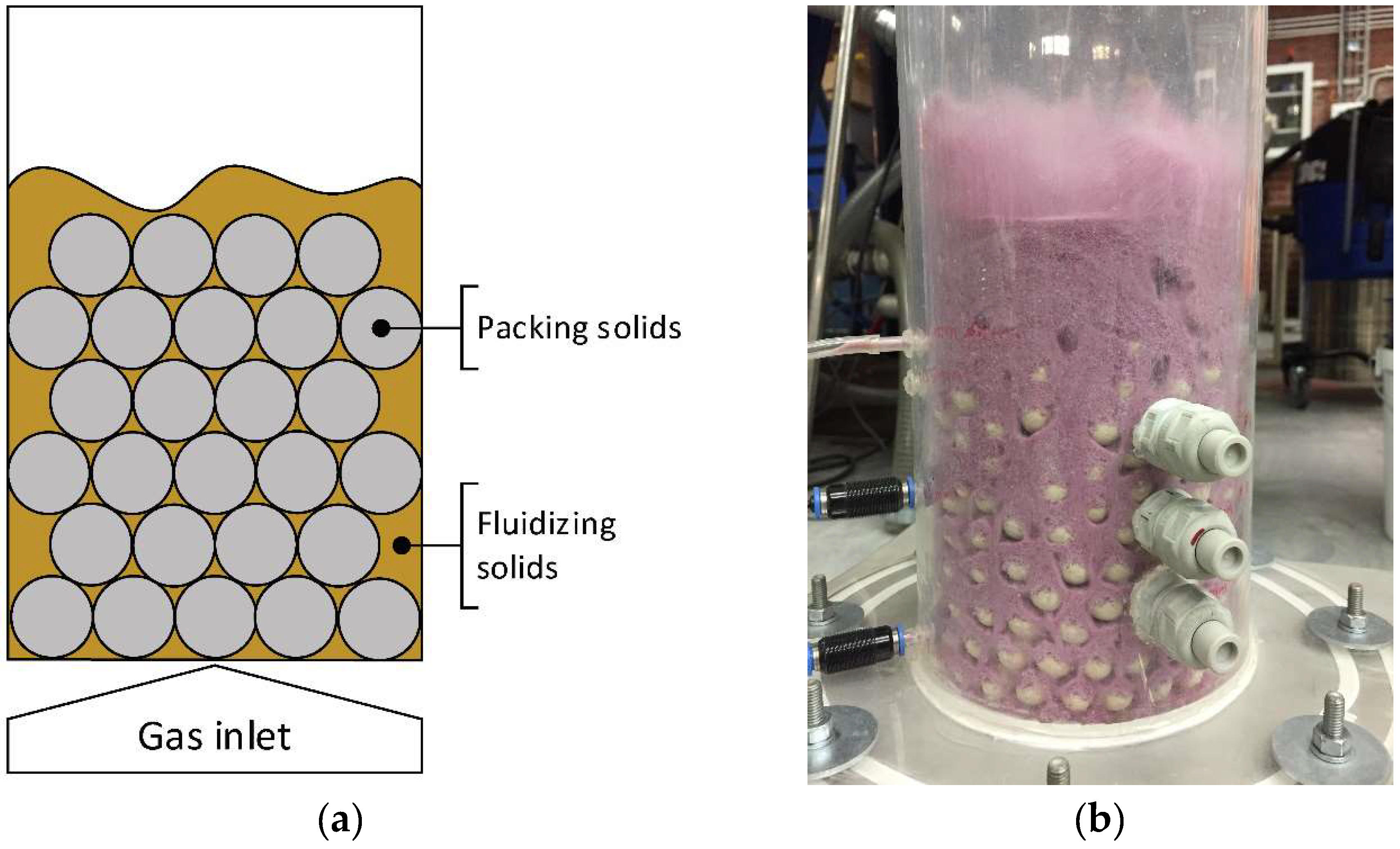
Reacting an active bed material solid with a gaseous component is a common application of fluidized beds, e.g., chemical looping combustion, combustion, gasification, fluid catalyst cracking, and chemical looping reforming. In many of these processes, mass transfer between the reacting gas and the active particle can prove a limiting step towards conversion, as demonstrated by e.g., Mattisson et al. [1]. According to the two-phase theory [2] only gas in the emulsion phase can interact with the bed material. The challenge of limited mass transfer between the bubble and emulsion phases can be addressed by means of using confined fluidized beds, i.e., inserting inert spheres of a size much larger than the bed material to break down the bubble-emulsion flow structure. It has been shown that doing so provides smooth fluidization and increases bed expansion [3,4]. This will also have other effects that can be beneficial to mass transfer, such as locally increased relative gas-particle velocity. The spheres, here called packing solids, form a stacked lattice from the bottom of the reactor, with fluidization of bed material (here referred to as fluidizing solids) occurring in the packing voids (Figure 1).
In the fuel reactor of a chemical looping combustion unit, combustible gas (e.g., gasification products of solid fuel, or gaseous fuel such as methane) reacts with a metal oxide bed material, to form water and carbon dioxide. It has been shown by modelling that mass transfer between bubbles, containing the bulk of the fuel, and the emulsion phase, containing reactive bed material, is a severe limitation to conversion [5]. This is especially true when looking at scaled-up units such as the proposed 1000 MW CLC design by Lyngfelt & Leckner [6] where the dense bed required can be several meters tall. Three major models for bubble-emulsion mass transfer are those by Kunii & Levenspiel [7], Sit & Grace and Davidson [8], and they all indicate that bubble size is inversely proportional to mass transfer. If Geldart type B particles are used for bed material the bubbles can grow to tens of centimetres in diameter [7], and limiting this size should improve mass transfer performance.
A system such as seen in Figure 1 was described by Gabor and Mecham [4,9,10] as a fluidized-packed bed, while Donsì et al. [11] named it confined fluidization. Gabor and Mecham [4] first investigated confined fluidized beds for the application of using the fluidizing solids as a heat transport medium in fluorination of spent uranium pellets, which acted as the packing solids. They investigated and formulated expressions for several basic fluidization properties such as pressure drop, solids mixing and bed expansion. Among other things it was found that the addition of fluidizing solids decreased the heat transfer coefficient by a factor two at the reactor walls, and eight at the top of the packing; reducing the need for in-bed cooling. Donsì & Ferrari [11,12] looked at expansion behaviour and pressure drop correlations, and Ziółkowski & Michalski [13] investigated pressure drop and minimum fluidization Reynolds numbers. More recently, Buczek and Zabierowski [14] investigated the hydrodynamics of confined fluidization with non-spherical packing solids. Farrell and Ziegler [15] investigated kinetics and mass transfer for catalytic hydrogenation of ethylene, where the packing solids had a catalytic surface. Mass transfer was measured between the gas and catalytic packing material and was found to be affected by factors such as size and amount of packing. Other methods for improving mass transfer in fluidized beds exist, such as adding wedges to reduce the reactor aperture [16] or the use of spouted beds [17].
In all, existing literature was found incomplete in two areas: Assessing the influence of the packing solids on the mass transfer between gas and fluidizing solids, and the maximum crossflow of solids across the packing. No previous research was found where confined fluidized beds have been used with the intent to improve bubble–emulsion mass transfer in combustion or gasification applications.
Having identified gaps in the existing body of literature, this paper aims to investigate the possible application, benefits and limitations, of confined fluidized beds in applications where mass transfer of gas between the emulsion and bubble phase is of importance to the process. Three main topics were identified as: Mass transfer improvement, segregation of packing and fluidizing solids and maximum vertical flow of fluidizing solids through the packing. The investigation was performed using cold flow modelling.
2. Materials and Methods
2.1. Experimental Setup
The cold flow model used consisted of a cylindrical acrylic reactor with an inner diameter of 12 cm and a height of 1 m. Fluidizing gas was fed through a porous metal plate. A bag filter with negligible pressure drop was mounted downstream to prevent particles from leaving the system. Pressure taps were located at the wind box and at 1 cm and 13.5 cm above the gas distributor. Pressure was measured using Huba Control transducers, digitalized through a NiDAQ A/D converter and recorded with NI LabVIEW. The air feed to the cold flow model was regulated via LabVIEW, using Bronkhorst mass flow meters. In cases where moisturized air was used, the temperature, pressure and moisture content were measured by a Vaisala PTU300.
Two types of fluidizing solids were used. For experiments on mass transfer silica gel was used. It was crushed and sieved to a particle size distribution with a mean size of 220 µm (range ca. 75–612 μm), and the dry bulk density was approximately 690 kg/m3. Due to the relatively high cost, complicated handling and limited availability in size and density of silica gel, olivine sand with a mean size of 116 µm, a particle density of 3135 kg/m3 and a bulk density of 1550 kg/m3 was used for all other experiments.
Four types of packing solids were used: Aluminium silicate balls (ASB) with a bulk density of 1400 kg/m3 and three different diameters (25.4, 12.7 and 6.35 mm), and expanded clay aggregate (ECA) with a bulk density of 280 kg/m3 and a typical size of 12 mm with slight variations.
2.2. Mass Transfer
Mass transfer was measured using silica gel as bed material and moisturized air as fluidizing gas. Similar experiments have previously been made by e.g., Qin et al. [18], who concluded that the adsorption rate of water onto the silica gel particles is mass transfer controlled for a relatively long time period. The air moisturization device used in these experiments was constructed using industry grade PVC piping. The main pipe outer diameter was 16 cm and it was 2 m tall. The pipe was capped in both ends, and in the top cap two holes were drilled as inlets for dry air and one as outlet for moisturized air. On the inside of the pipe the inlets were connected to tubing of approximately the same length as the pipe; perforated at the bottom. This caused the dry air to bubble up through a water column of 1.5 m height and become moisturized. The moisture content varied between 75–95% relative humidity depending the temperature of the room and the dry air.
The cold flow model was placed upon a scale which logged the total system weight over the duration of each experiment, and weight increase logged then corresponded to the mass of water adsorbed on the particles. Using this data together with the recorded moisture content of the air, a mass transfer rate coefficient, k, was calculated according to Equations (1)–(4). The water vapor concentration in the bulk of the gas was calculated assuming a logarithmic mean of the in- and outgoing concentrations, Equation (2). The concentration of water on the particle surface was calculated by performing a calibration experiment. In the experiment the fluidizing solids were completely saturated with water. Knowing that the concentrations on the particle surface and in the bulk gas were equal at this point, a material dependent coefficient, α, was obtained (Equation (4)). For the material used here α = 0.0241 kg/m3. Assuming linearity, this corresponds to a Henry’s law constant of 0.36 g/g, to be compared to e.g., [19] who report a value of ca. 0.44 g/g for Davidson Bead Gel.
Five different cases were tested: One for each type of packing solids and a comparative experiment using the same bed mass as in the other cases, but without packing. For all cases the superficial gas velocity was u0 = 29.5 cm/s. The experiments are summarized in Table 1.
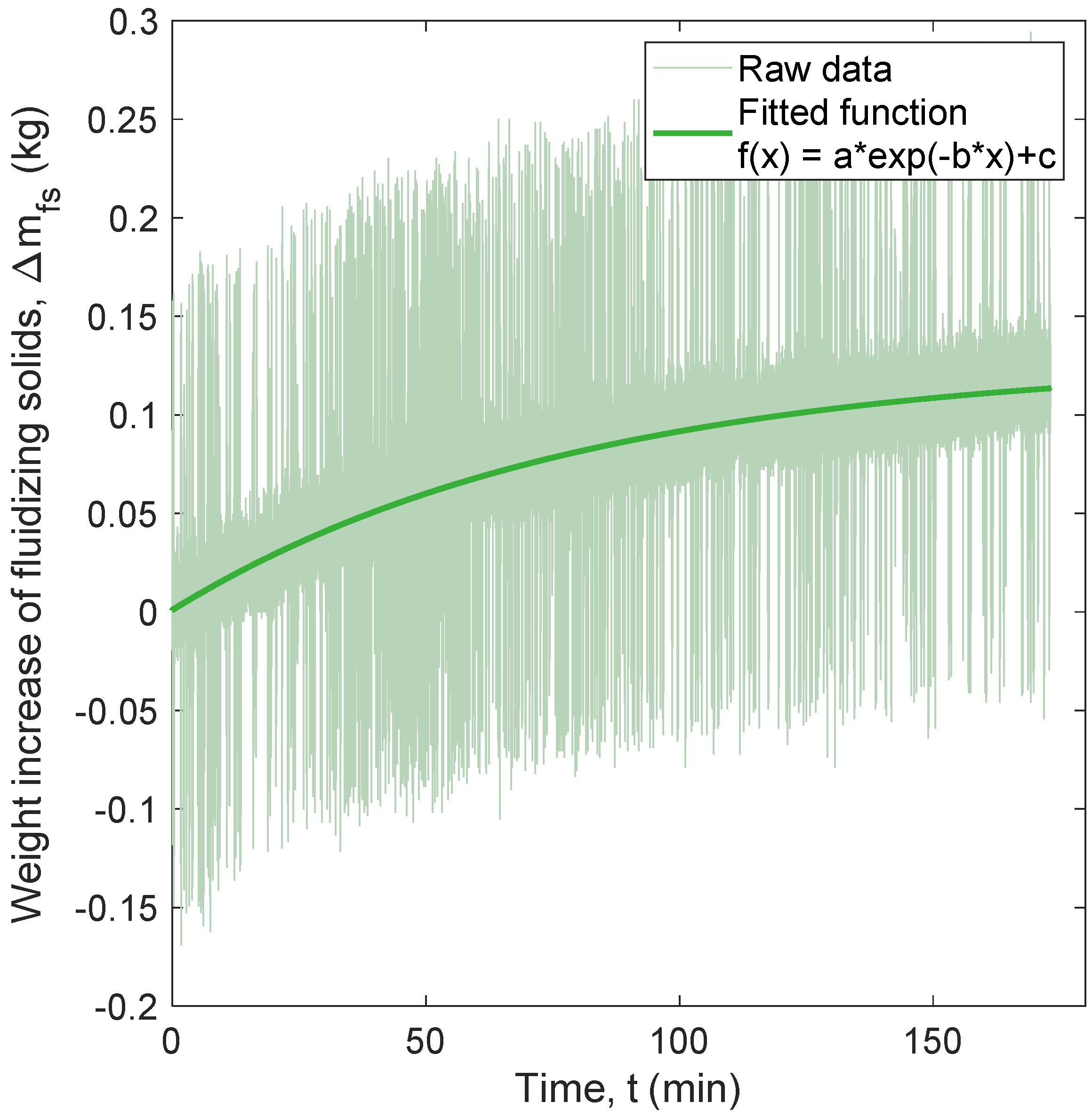
Due to excessive noise the signals acquired from the scale required conditioning before the mass transfer coefficients could be calculated. They were filtered with a Lowess-type smoothing filter and then fitted to an exponential expression of the type . The signals were also down sampled from 10 Hz to 1 Hz, matching the native sampling frequency of the relative humidity meter. An example of raw and conditioned logged weight can be seen in Figure 2. In addition to this, only the first 10 minutes of the sampled data was used. This ensured that the adsorption was mass-transfer limited (i.e., the mass transfer coefficient was constant).
2.3. Vertical Segregation of Fluidizing Solids
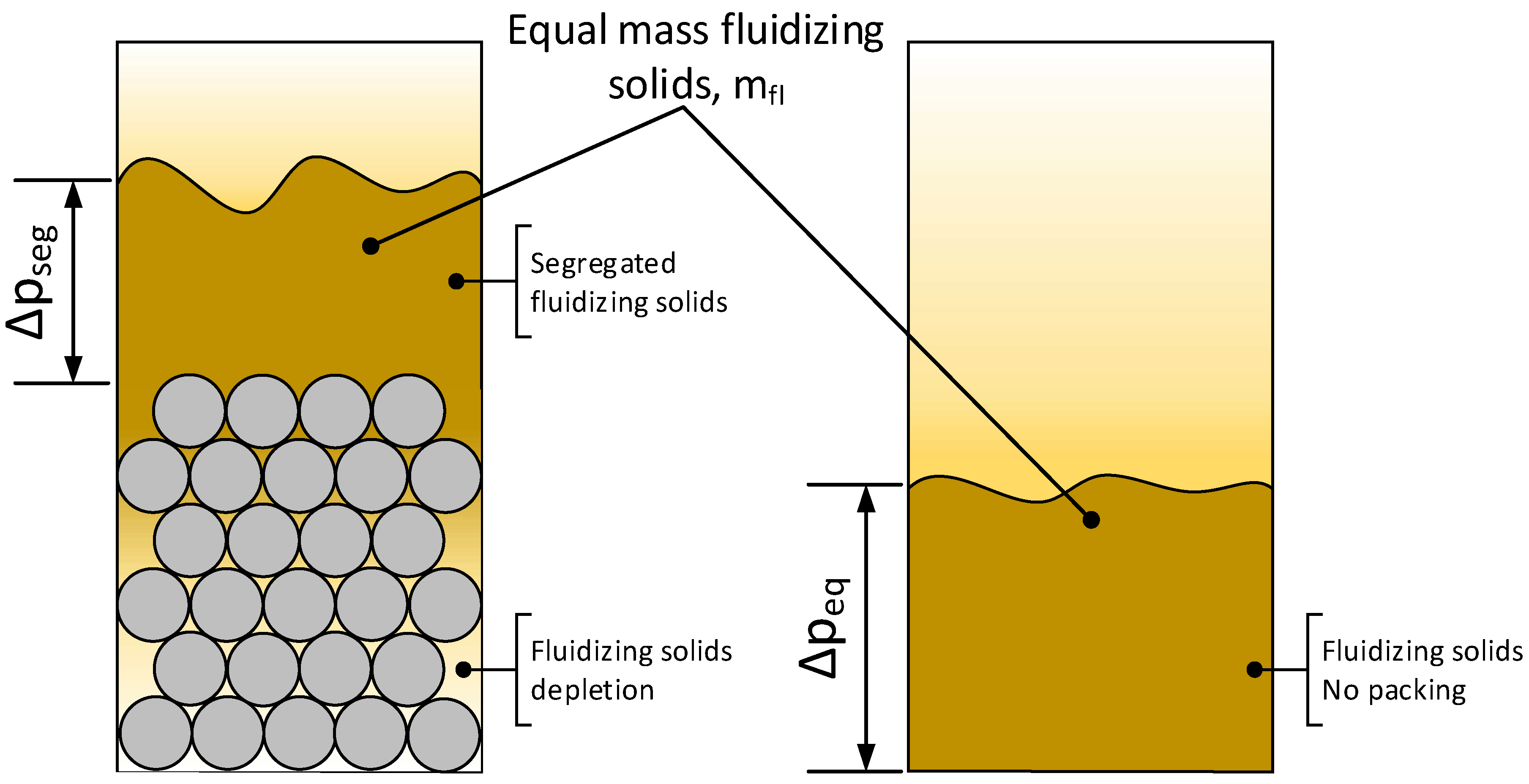
Overall pressure drop as well as segregation between fluidizing solids and packing solids were assessed through pressure measurements. When fluidizing a stationary confined fluidized bed consisting of fluidizing solids and packing solids with a total height equal to the upper pressure tap, the bed expands and the inventory of fluidizing solids above this upper pressure tap can be easily determined (Figure 3). With this, the voidage of the fluidizing solids inside the voids of the packing solids, , can be calculated, as presented in Equations (5) and (6).
Six different cases were tested, as presented in Table 2. ECA packing and fluidizing solids did not segregate under the conditions tested but mixed to a large extent. Thus, the bed expansion, Xexp, was used to indicate an average voidage of the fluidizing solids, see Equations (7) and (8), assuming that the void space of the packing solids increased linearly with the bed expansion.
2.4. Crossflow of Fluidizing Solids
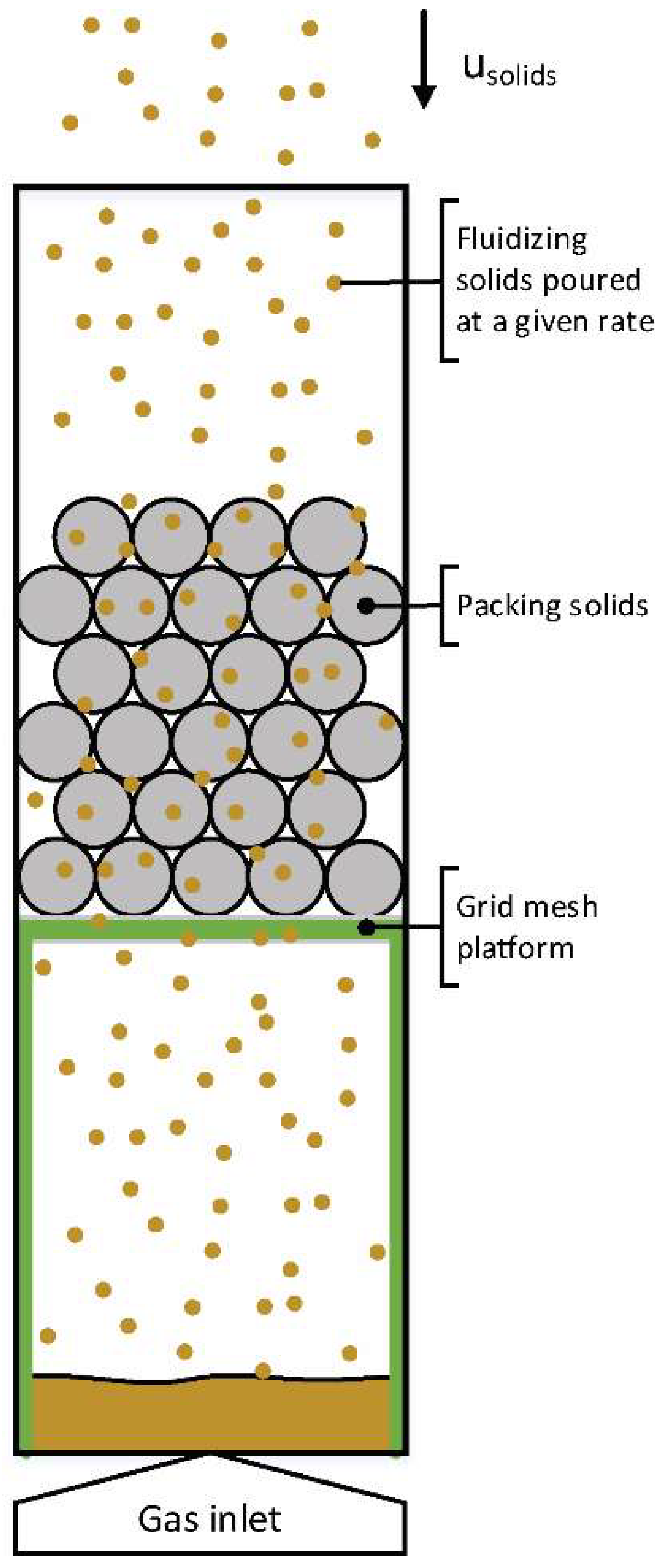
The maximum vertical crossflow of fluidizing solids through the packing solids was measured. A device was constructed to allow the pouring of fluidizing solids at a constant rate. It consisted of a funnel shaped reservoir with sharply inclined walls, where the bottom opening was attached to a knife gate valve. The valve had previously been calibrated by measuring the time it took to pour a certain mass of solids on to a scale. A known mass flow of solids could thus be poured by adjusting the opening of the valve. By pouring the fluidizing solids over packing suspended on a platform covered by a coarse metal mesh, through which the fluidizing solids could move freely within the range of solids fluxes investigated, a maximum rate could be found (Figure 4) before a choke point was reached and fluidizing solids started building up on top of the packing. A small amount of gas at u0 = 3 cm/s was added from below in order to prevent bed material from getting stuck in the packing, while staying well under conditions where the gas velocity inside the packing voids would be so high that it pushes the fluidizing solids back up. Due to the ability of ECA packing to enter another mode of fluidization where the packing is fluidizing and suspended by the particles, an additional point with a higher velocity of u0 = 18 cm/s was tested for ECA packing and, for comparison, the similarly sized 12.7 mm ASB packing.
3. Results and discussion
3.1. Mass Transfer
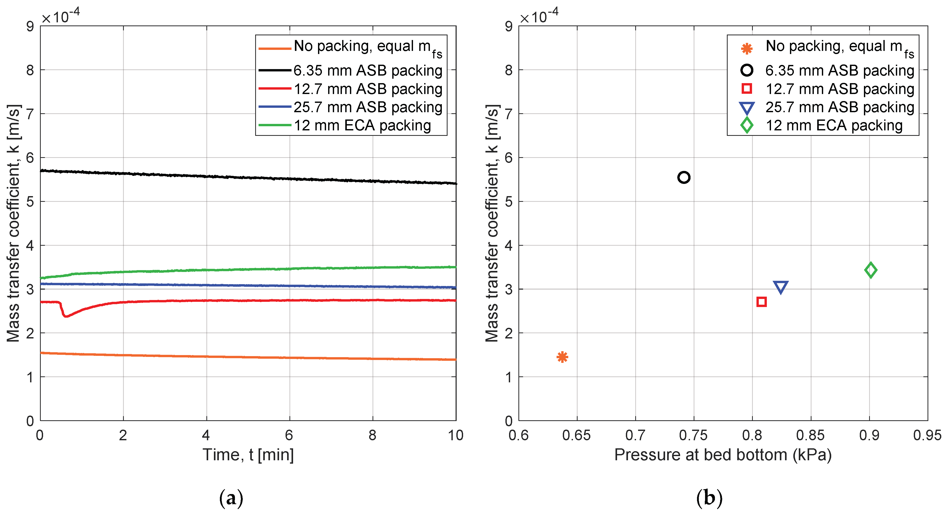
The mass transfer coefficient was found constant in the time period selected, suggesting that adsorption was mass transfer controlled (as opposed to kinetically controlled), see Figure 5a. An improvement in mass transfer by a factor 1.9–3.8 was found under the conditions tested here, see Figure 5b. The largest improvement was observed using 6.35 mm ASB packing solids and the smallest improvement was with the 12.7 mm ASB packing solids. ECA packing solids performed better than the 12.7 and 25.4 mm ASB packing solids and gave an improvement of a factor 2.4. No splash zone formed in the experiments using ECA packing, as opposed to ASB packing.
When considering the result smallest size of packing, which performed considerably better than the others, care should be taken. This due to that the diameter ratio of the very largest silica gel particles in the particle size distribution (ca. 612 μm), to the packing, exceeded the maximum 0.090 recommended by Sutherland et al. [3] for good quality of fluidization. It is thus possible that fluidisation problems occurred even though this number was not exceeded when considering the average particle size. For the other packings, the maximum ratio was not exceeded.
The pressure drop was higher with all forms of packing than without, proposing a trade-off situation between packing parameters and mass transfer.
3.2. Pressure Drop and Vertical Segregation of Fluidizing Solids
The pressure drop over the bed was measured and compared to two different scenarios without packing: Equal mass of fluidizing solids and equal bed height. The pressure drop of the packing solids without addition of fluidizing solids was measured separately and found to be close to zero. Adding packing solids and fluidizing solids together contributed to a higher bed pressure drop than a conventional fluidized bed with equal fluidizing solids mass. Donsì et al. [11] hypothesized that this increase is present due to abrasive interaction between the bed material and packing. Another hypothesis is that drag forces increase due to the collapse of the conventional bubble-emulsion flow structure—negating low pressure paths (bubbles) to form. It was also measured that a confined fluidized bed however has a lower total pressure drop than a conventional fluidized bed of the same height. As previously observed by e.g., Mandal [20] the pressure drop decreased slightly with increased fluidization velocity, in the range tested. This effect can likely be attributed to segregation of packing and fluidizing solids, since the mentioned interaction decreases with the amount of fluidizing solids in the packing. A bed without packing, but with equal height as one with, exhibited a higher overall pressure drop than experiments when packing was used. In Figure 6a pressure drop normalized by the mass of fluidizing solids is shown. Since bed height and mass were varied, this paints a more accurate picture of the difference in pressure drop related to the packing material used than the total pressure drop. As expected, the experiments without packing showed similar pressure drops when normalized. From Figure 6b, which shows the pressure drop from fluidizing solids inside the packing, it can be seen that the size of the packing solids affected the pressure drop: Increasing with packing size. The 6.35 mm packing was tested but it was observed that fluidizing solids gathered along one side of the bed, letting large amounts of gas bypass the bed. This led to a significantly lower pressure drop compared to packings of larger size. For this reason, it was omitted from Figure 6 and Figure 7. With ECA packing, pressure drop did not increase significantly with superficial gas velocity. It was observed for this packing that the packing solids initially floated on top of the fluidizing solids. When the bed was fluidized at u0 = 18 cm/s the packing started to move slightly. The effect became more apparent when the velocity was increased further, and the fluidizing solids and packing solids were co-fluidized.
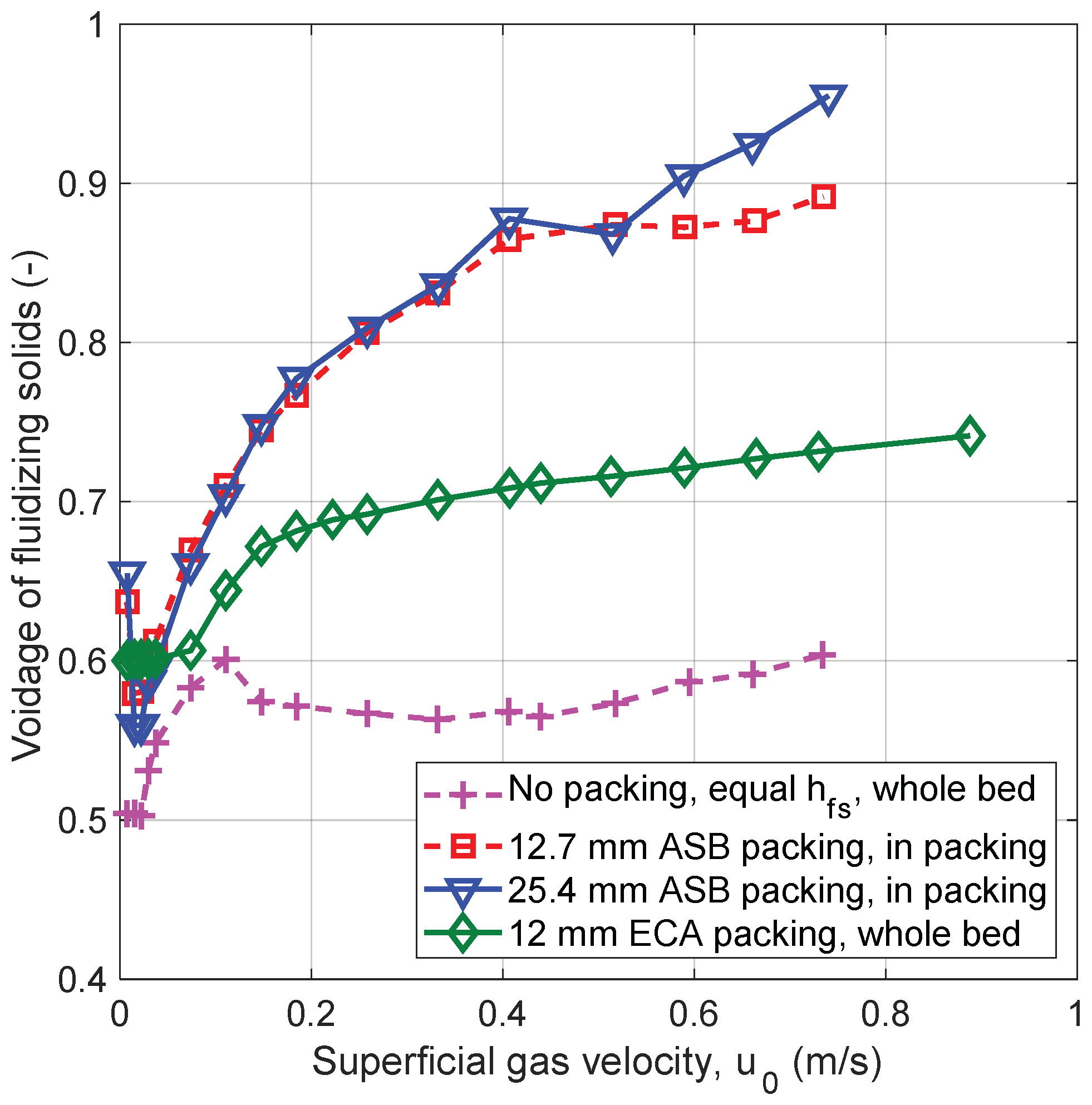
Segregation of bed material and packing was expected to have an impact on the mass transfer performance of the confined fluidized bed since bubbles can grow freely if the fluidizing solids are not suspended within the packing solids. Figure 7 shows that the voidage of the fluidizing solids inside the packing increased with superficial gas velocity, indicating that fluidizing solids move from the voids in the packing solids to the space above the packing. The voidage of a bed without packing solids is shown for comparison. Voidage was very similar for the two larger ASB packings tested. The ECA packing did, as previously mentioned, act as flotsam rather than being stationary. This meant segregation could not be measured by the method used for the other packings. For ECA Figure 7 instead shows an estimation of the average voidage and how it expanded uniformly with increased gas flow.
3.3. Crossflow of Fluidizing Solids
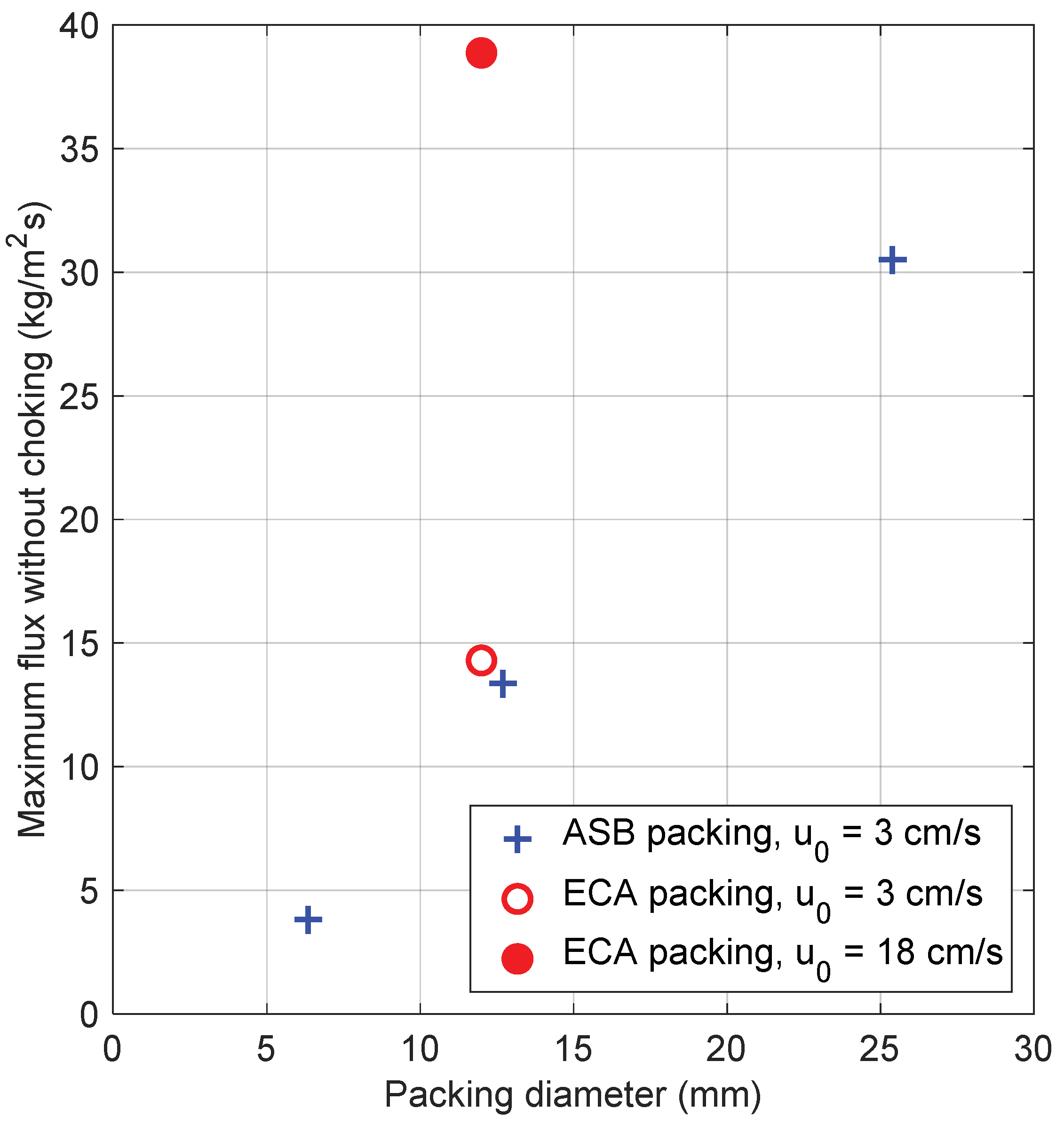
For experiments with ASB packing a linear increase of maximum flux was seen with increased packing size (Figure 8). For ASB packing sizes of 6.35, 12.7 and 25.4 mm the maximum flux was 3.8, 13.35 and 30.8 kg/m2s respectively. A test with 12.7 ASB mm packing at u0 = 18 cm/s concluded that these values do not increase with gas velocity. When ECA packing was used at u0 = 3 cm/s, no significant difference was seen as compared to ASB packing. When fluidization velocity was increased to a level where the packing was fluidized, u0 = 18 cm/s, the maximum solids flux increased significantly to 38 kg/m2s. In the design of a 1000 MWth CLC reactor, Lyngfelt found that the necessary flux in the fuel reactor is 68.8 kg/m2s, which shows that crossflow of solids may pose a limitation for applications where the reactor design which require large amounts of solids to pass vertically through the bed.
4. Conclusions
Reflecting on the experiments and results presented here, the following conclusions were drawn:
- Mass transfer can be successfully increased using spherical packing in a fluidized bed. From this perspective, packing size mattered little in the conducted experiments at cold conditions, as did packing density, for all but the smallest packing investigated. This packing was however observed to have fluidization problems under some conditions.
- Low-density packing floated as a plug partially or fully infiltrated by bed material depending on fluidization velocity. Segregation occurred in the opposite way as with high-density packing. That is: Bed material free from packing gathering under the packing rather than above it. The result was a highly porous bed with good mass transfer properties.
- Pressure drop increased when heavy packing was used as compared to a non-packed bed with the same mass of fluidizing solids. It was observed to decrease with increased gas velocity as the bed became more and more segregated. For light packing the pressure drop was also elevated but unlike the heavy packing, pressure drop remained rather constant when gas velocity was changed.
- Vertical cross-flow of solids was significantly reduced in a confined fluidized bed as compared to a regular fluidized bed. As a solution to this problem it was suggested to use light, floating packing at fluidization velocities high enough to ensure a good mixing of the packing within the bed material. This led to a more than two-fold increase in maximum cross-flow flux.
Author Contributions
Conceptualization, J.A.; formal analysis, J.A.; funding acquisition, J.A. and M.R.; investigation, J.A.; methodology, J.A. and D.P.; project administration, M.R.; supervision, D.P., M.R. and A.L.; visualization, J.A.; writing—original draft, J.A.; writing—review & editing, J.A., D.P. and M.R.
Funding
The research leading to these results has received funding from the research foundation of Göteborg Energi, grant no. 17-07 and the ÅForsk foundation grant no. 17-379.
Conflicts of Interest
The authors declare no conflict of interest. The funders had no role in the design of the study; in the collection, analyses, or interpretation of data; in the writing of the manuscript, or in the decision to publish the results.
Notation
| Symbol | Unit | Description |
| Total particle surface area | ||
| Concentration | ||
| Mass transfer coefficient | ||
| Henry’s law constant | ||
| Mass | ||
| Time | ||
| Fraction | ||
| Surface concentration coefficient | ||
| Voidage | ||
| Density | ||
| Abbreviation | Description | |
| Adsorbed | ||
| In bulk gas flow | ||
| Particle surface | ||
| Inlet | ||
| Outlet | ||
| Fluidizing solids | ||
| Saturated | ||
| Calibration | ||
| Packing solids | ||
| Height | ||
| Segregation | ||
| Total | ||
| Expansion | ||
| Particle |
References
- Mattisson, T.; Jerndal, E.; Linderholm, C.; Lyngfelt, A. Reactivity of a spray-dried NiO/NiAl2O4 oxygen carrier for chemical-looping combustion. Chem. Eng. Sci. 2011, 66, 4636–4644. [Google Scholar] [CrossRef]
- Grace, J.R.; Clift, R. On the two-phase theory of fluidization. Chem. Eng. Sci. 1974, 29, 327–334. [Google Scholar] [CrossRef]
- Sutherland, J.P.; Vassilatos, G.; Kubota, H.; Osberg, G.L. The effect of packing on a fluidized bed. AIChE J. 1963, 9, 437–441. [Google Scholar] [CrossRef]
- Gabor, J.D.; Mecham, W.J. Engineering Development of Fluid-Bed Fluoride Volatility Processes. Part 4. Fluidized-Packed Beds: Studies of Heat Transfer, Solids-Gas Mixing, and Elutriation; Argonne National Laboratory: Lemont, IL, USA, 1965. [Google Scholar]
- Aronsson, J.; Pallarès, D.; Lyngfelt, A. Modeling and scale analysis of gaseous fuel reactors in chemical looping combustion systems. Particuology 2017, 35, 31–41. [Google Scholar] [CrossRef]
- Lyngfelt, A.; Leckner, B. A 1000 MWth boiler for chemical-looping combustion of solid fuels—Discussion of design and costs. Appl. Energy 2015, 157, 475–487. [Google Scholar] [CrossRef]
- Kunii, D.; Levenspiel, O. Fluidization Engineering, 2nd ed.; Brenner, H., Ed.; Butterworth-Heinemann: Newton, MA, USA, 1991; ISBN 0-409-90233-0. [Google Scholar]
- Oka, S. Fluidized Bed Combustion; CRC Press: Boca Raton, FL, USA, 2003; ISBN 9781420028454. [Google Scholar]
- Gabor, J.D. Lateral solids mixing in fludized-packed beds. AIChE J. 1964, 10, 345–350. [Google Scholar] [CrossRef]
- Gabor, J.D.; Mecham, W.J. Radial gas mixing in fluidized-packed beds. Ind. Eng. Chem. Fundam. 1964, 3, 60–65. [Google Scholar] [CrossRef]
- Donsì, G.; Ferrari, G.; Formisani, B. Expansion behaviour of confined fluidized beds of fine particles. Can. J. Chem. Eng. 1989, 67, 185–190. [Google Scholar] [CrossRef]
- Donsì, G.; Ferrari, G.; Formisani, B.; Longo, G. Confined fluidization of fine particles in a packed bed of coarse particles: Model and experimental description. Powder Technol. 1990, 61, 75–85. [Google Scholar] [CrossRef]
- Ziółkowski, D.; Michalski, J. Onset of fluidization of fines in an organized system within voids of packings formed of spherical elements. Chem. Eng. Sci. 1992, 47, 4007–4016. [Google Scholar] [CrossRef]
- Buczek, B.; Zabierowski, P. Confined fluidization of fines in fixed bed of coarse particles. Chem. Process Eng. 2016, 37, 545–557. [Google Scholar] [CrossRef] [Green Version]
- Farrell, R.J.; Ziegler, E.N. Kinetics and mass transfer in a fluidized packed-bed: Catalytic hydrogenation of ethylene. AIChE J. 1979, 25, 447–455. [Google Scholar] [CrossRef]
- Guío-Pérez, D.C.; Hofbauer, H.; Pröll, T. Effect of ring-type internals on solids distribution in a dual circulating fluidized bed system-cold flow model study. AIChE J. 2013, 59, 3612–3623. [Google Scholar] [CrossRef]
- Hoffmann, T.; Bedane, A.H.; Peglow, M.; Tsotsas, E.; Jacob, M. Particle–Gas Mass Transfer in a Spouted Bed with Adjustable Air Inlet. Dry. Technol. 2011, 29, 257–265. [Google Scholar] [CrossRef]
- Qin, K.; Thunman, H.; Leckner, B. Mass transfer under segregation conditions in fluidized beds. Fuel 2017, 195, 105–112. [Google Scholar] [CrossRef]
- Sircar, S.; Rao, M.B.; Golden, T.C. Drying of gases and liquids by activated alumina. Stud. Surf. Sci. Catal. 1996, 99, 629–646. [Google Scholar] [CrossRef]
- Mandal, D.; Vinjamur, M.; Sathiyamoorthy, D. Hydrodynamics of beds of small particles in the voids of coarse particles. Powder Technol. 2013, 235, 256–262. [Google Scholar] [CrossRef]
Figure 1.
(a) Conceptual representation of a confined fluidized bed. (b) Photo of a confined fluidized bed using aluminium silicate ball packing solids and silica gel fluidizing solids.
Figure 1.
(a) Conceptual representation of a confined fluidized bed. (b) Photo of a confined fluidized bed using aluminium silicate ball packing solids and silica gel fluidizing solids.

Figure 2.
Raw and conditioned signal from the 12 mm ECA case.

Figure 3.
Conceptual representation of segregation in a confined fluidized bed.

Figure 4.
Principal drawing of solids crossflow measurement setup.

Figure 5.
Comparison of mass transfer in fluidized and confined fluidized beds, with varying types of packing. (a) Mass transfer coefficient over time. (b) Average mass transfer coefficient as a function of pressure drop.
Figure 5.
Comparison of mass transfer in fluidized and confined fluidized beds, with varying types of packing. (a) Mass transfer coefficient over time. (b) Average mass transfer coefficient as a function of pressure drop.

Figure 6.
(a) Pressure drop of a fluidized bed with or without packing, normalized by total mass of fluidizing solids. (b) Pressure drop over the packing of a confined fluidized bed of a certain height, normalized by mass of fluidizing solids inside the packing.
Figure 6.
(a) Pressure drop of a fluidized bed with or without packing, normalized by total mass of fluidizing solids. (b) Pressure drop over the packing of a confined fluidized bed of a certain height, normalized by mass of fluidizing solids inside the packing.

Figure 7.
Voidage correlated to superficial gas velocity.

Figure 8.
Maximum crossflow of fluidizing solids over the packing.


Table 1.
Description of experiments with silica gel.
| Packing Type | Bed Height 1 (cm) | Bed Mass (g) | Packing Mass (g) | Notes |
|---|---|---|---|---|
| 6.35 mm ASB | 13.5 | 464 | 2297 | |
| 12.7 mm ASB | 13.5 | 467 | 2134 | |
| 25.4 mm ASB | 13.5 | 467 | 1990 | |
| 12 mm ECA | 13.5 | 475 | 410 | |
| No packing | 6 | 475 | - | Equal bed mass |
1 Unfluidized
Table 2.
Description of experiments with olivine.
| Packing Type | Bed Height (cm) | Bed Mass (g) | Packing Mass (g) | Notes |
|---|---|---|---|---|
| 6.35 mm ASB | 13.5 | 1000 | 2145 | |
| 12.7 mm ASB | 13.5 | 1035 | 2105 | |
| 25.4 mm ASB | 13.5 | 1180 | 1992 | |
| 12 mm ECA | 13.5 | 1050 | 440 | |
| No packing | 6 | 1180 | - | Equal bed mass |
| No packing | 13.5 | 2415 | - | Equal bed height |
© 2019 by the authors. Licensee MDPI, Basel, Switzerland. This article is an open access article distributed under the terms and conditions of the Creative Commons Attribution (CC BY) license (http://creativecommons.org/licenses/by/4.0/).
Share and Cite
MDPI and ACS Style
Aronsson, J.; Pallarès, D.; Rydén, M.; Lyngfelt, A. Increasing Gas–Solids Mass Transfer in Fluidized Beds by Application of Confined Fluidization—A Feasibility Study. Appl. Sci. 2019, 9, 634. https://doi.org/10.3390/app9040634
AMA Style
Aronsson J, Pallarès D, Rydén M, Lyngfelt A. Increasing Gas–Solids Mass Transfer in Fluidized Beds by Application of Confined Fluidization—A Feasibility Study. Applied Sciences. 2019; 9(4):634. https://doi.org/10.3390/app9040634
Chicago/Turabian StyleAronsson, Jesper, David Pallarès, Magnus Rydén, and Anders Lyngfelt. 2019. "Increasing Gas–Solids Mass Transfer in Fluidized Beds by Application of Confined Fluidization—A Feasibility Study" Applied Sciences 9, no. 4: 634. https://doi.org/10.3390/app9040634
Note that from the first issue of 2016, this journal uses article numbers instead of page numbers. See further details here.