Article

An Embedded Gateway with Communication Extension and Backup Capabilities for ZigBee-Based Monitoring and Control Systems

1
Graduate Institute of Applied Science and Technology, National Taiwan University of Science and Technology, Taipei 106, Taiwan
2
Department of Electrical and Electronic Engineering, Chung Cheng Institute of Technology, National Defense University, Taoyuan 335, Taiwan
3
Department of Computer Science and Information Engineering, Chinese Culture University, Taipei 111, Taiwan
4
Department of Electrical Engineering, National Taiwan University of Science and Technology, Taipei 106, Taiwan
5
Department of Biomedical Engineering, National Defense Medical Center, Taipei 114, Taiwan
*
Author to whom correspondence should be addressed.
Appl. Sci. 2019, 9(3), 456; https://doi.org/10.3390/app9030456
Submission received: 22 December 2018 / Revised: 23 January 2019 / Accepted: 26 January 2019 / Published: 29 January 2019

Abstract

:
ZigBee wireless sensor devices possess characteristics of small size, light weight, low power consumption, having up to 65535 nodes in a sensor network, in theory. Therefore, the ZigBee wireless sensor network (WSN) is very suitable for use in developing monitoring and control (MC) applications, such as remote healthcare, industrial control, fire detection, environmental monitoring, and so on. This dissertation is directed towards the research on the issues of communication extension and backup, encountered in creating ZigBee-based MC systems for military storerooms, together with providing associated solutions. We design an embedded gateway that possesses wired network (Ethernet) and wireless communication (GSM) backup capability. The gateway can not only easily extend the monitoring distance of the ZigBee-based MCS, but can also solve the problem that some military zones do not have wire networks or possess communication blind spots. The results of this dissertation have been practically applied in constructing a paradigm monitoring system of a military storeroom. It is believed that the research results could be a useful reference for developing ZigBee-based MCSs in the future.

1. Introduction

Based on short-range communication protocols, wireless sensor networks (WSNs) have a communication range of 100 meters. If a greater range is required, multi-hop modes can be used to extend coverage. However, more routes must be deployed as distance increases, making the system costly and difficult to maintain. Monitoring systems built on WSNs can use other methods to extend their communication distance; for example [1,2,3,4,5], used a gateway with multiple communication nodes. Sha et al. designed a multi-mode gateway that included wireless local area networks (WLAN) and 3G/4G mobile data networks [3], enabling healthcare professionals and the family of patients in a hospital setting to connect to the hospital monitoring system via different communication networks.
Although the gateway design above provides users with greater flexibility, the remote monitoring functions fail if WLAN and mobile data networks are unstable. Military warehouses, for example, are usually located in regional areas with poor telecommunication infrastructure, making it extremely problematic to effectively build a WSN monitoring system. Wired communication systems commonly use twisted pair cabling for dial-up networking, but the problem with this approach is that the quality of the connection is often unstable. Although wireless networks have greater signal transmission range and can enable better network access in remote areas, signal quality is determined by distance to the mobile phone tower. In areas with poor coverage, therefore, it is essential that remote monitoring systems are designed with back-up capabilities for communication networks.
Ju et al. and Maleki et al. set out the communication architecture for a monitoring system that combines both WSN and wired networks [6,7]. The advantage of this hybrid approach is that, should the wired network fail, the system can immediately switch to communicating via WSN. The disadvantage is that such systems are extremely complex and costly to build, as well as difficult to maintain. In the hybrid monitoring mechanism developed by Wei et al. [8], when the wired network shows errors or irregularities, these data are conveyed back to the server via pre-allocated routes and used to enhance the transmission rate of the wireless network.
According to the results of [6,7], it is obvious that the monitoring and control system must have communication backup capabilities. However, the solution to the system backup mentioned in the above articles is achieved by using switching of wired and wireless communication networks. The monitored area is in a location where signal coverage is poor, and therefore we must consider other communication methods (such as mobile communication) to prevent system failure.
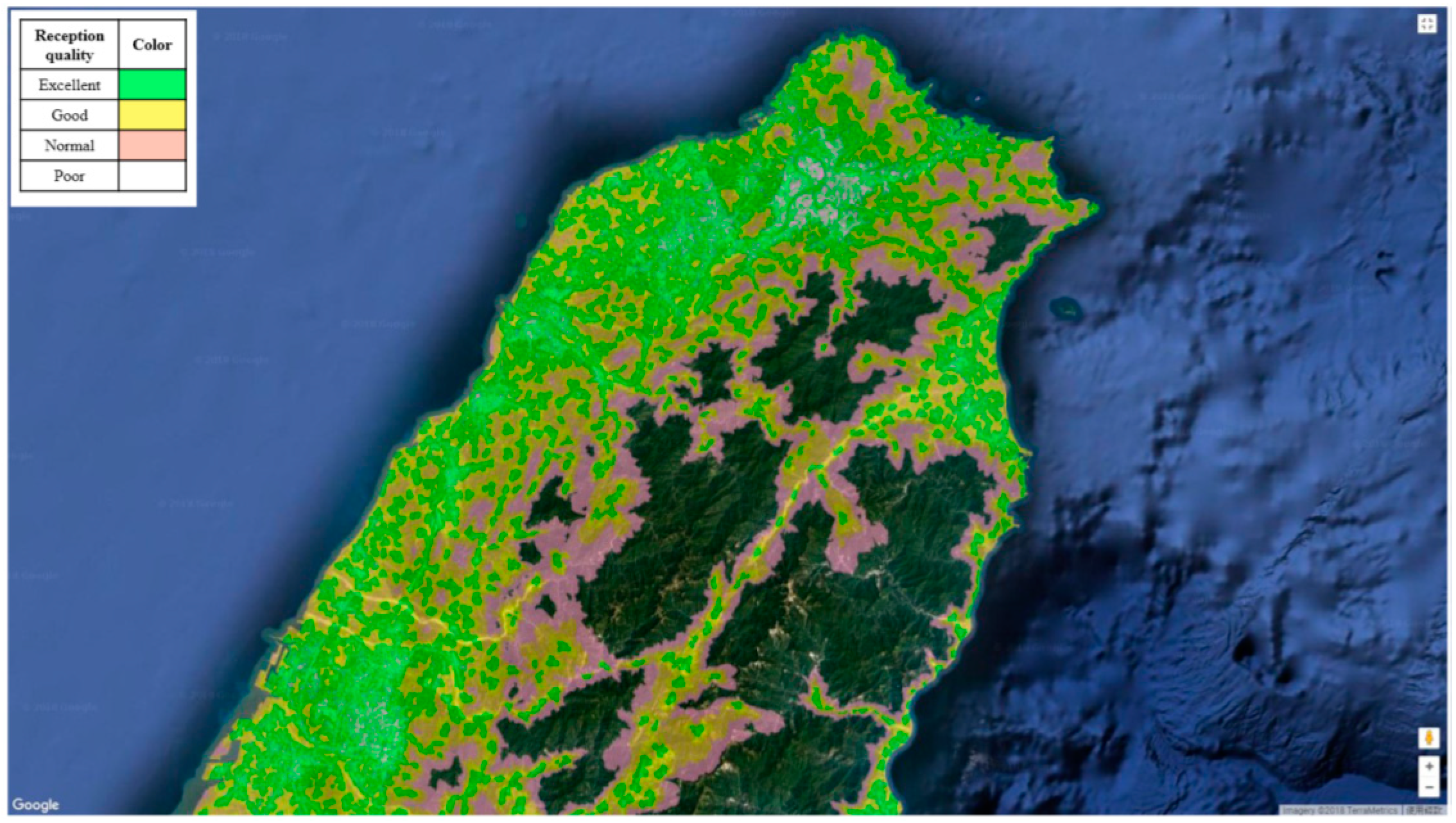
The National Communications Commission (NCC) of Taiwan provides a Mobile Communications Service Information System [9], which can be used to search for the signal coverage and reception quality of 3G/4G mobile phone networks in any area (see Figure 1).
In the figure, green indicates areas with high reception quality. This means that mobile phone users in these areas can place calls and transmit data over a stable and consistent connection. The yellow regions have standard reception quality. Phone calls are uninterrupted and audio is clear, but the data connection may occasionally be unstable. The orange zones have acceptable reception quality, meaning that data connections may be partially unstable. Finally, the white or transparent zones have poor reception, meaning it is difficult to successfully make calls and audio is unclear. Most of the mountainous areas in Taiwan are not covered by mobile communications, and the system does not mark additional colors, so the mountains present the dark green of the original satellite imagery. If WSNs were built in the yellow and orange zones, these would be considered communication blind spots. We would be limited to using GSM/SMS [10,11,12] communication for remote monitoring.
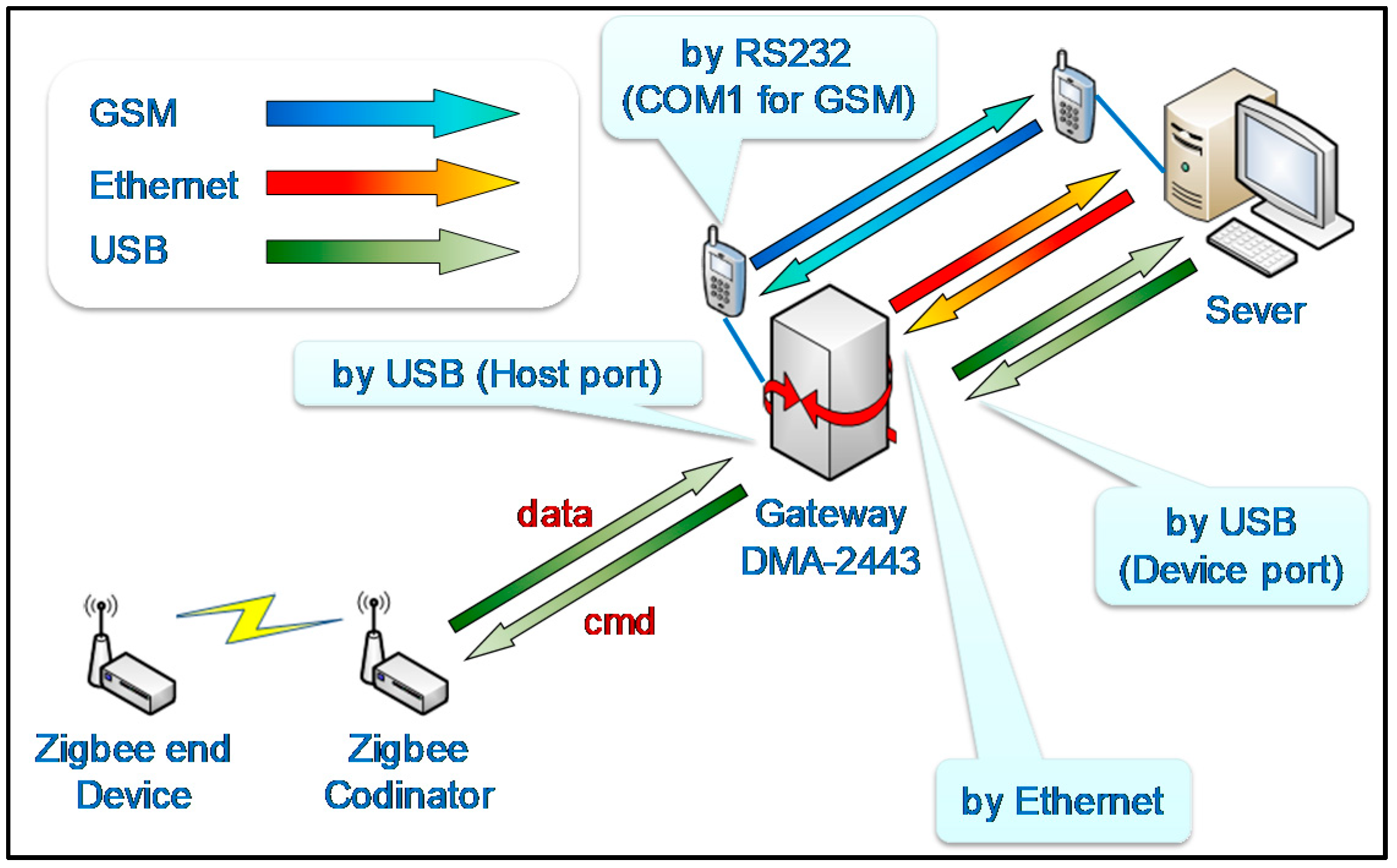
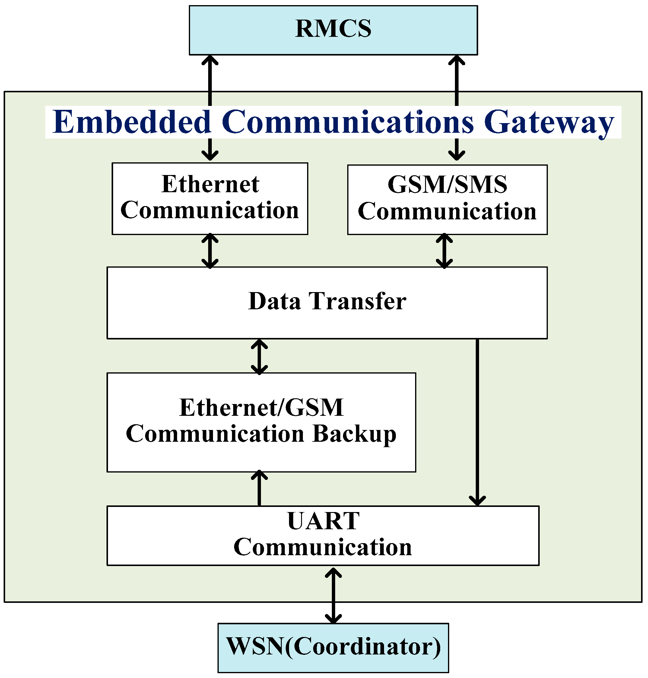
Using GSM/SMS signals, which can more easily cover multiple monitoring areas, we developed an anti-blind spot gateway, which we deployed in monitoring systems for military warehouses in remote locations. We gathered data on each ZigBee-controlled device.
When wireless networks are operating as expected, this gateway uses the Ethernet model to communicate with the remote monitoring server. In the event of network failure, a back-up mechanism is immediately activated, and the system automatically switches to communicating via GSM/SMS. This offers a solution to the current problem of being unable to implement monitoring systems in military warehouses located in communication blind spots.
The Taiwan National Army has many warehouses in remote areas and lacks the infrastructure for network data communication. This type of warehouse requires a communication backup mechanism to ensure that monitoring data can be transmitted to the monitoring center. Therefore, the design of the gateway in the WSN system is very important. How the gateway communicates with the wireless sensor network and how to automatically switch backup communication is the main problem in this study.

2. Framework Design of Gateway

As a solution to the monitoring system problems described above, we designed an embedded gateway with an automatic back-up mechanism. The gateway gathers data from each sensor node in the monitored area and then transmits the data to the remote server as shown in Figure 2. As mentioned above, we define priority levels for communication channels. The highest level is “USB” communication. The second is communicating over “Ethernet”. The lowest priority level is “GSM/SMS” live data communication. When the gateway receives sensor data from the Zigbee Coordinator, the data will be transmitted to the monitoring server according to the preset transmission priority level. In addition, the priority levels for communication channels can be adjusted from the monitoring server by the user, so as to adapt to different types of transmission application scenarios.

2.1. Gateway: Functional Requirements Analysis

We highlight the following key functions based on Figure 2:

2.1.1. Ability to Communicate with Remote Server via Ethernet

Conventionally, WSN coordinators physically connect to the server through USB (maximum communication range: 5 m), RS232 (15 m), and RS485 (1,219 m), for example. However, if the target area exceeds the communication range of these cables, then the monitoring system cannot be operated. If the military warehouse is equipped with Ethernet (which is the case in most military bases in Taiwan), then we could use this communication method to extend the range of remote monitoring.

2.1.2. Ability to Communicate with Remote Server via GSM

Many military warehousing facilities are located a distance from the main base because they are used to store flammable or explosive materials, such as ammunition or fuel. Ammunition warehouses in particular may be located in remote, unpopulated mountainous regions. Due to cost considerations, these warehouses may not be equipped with Ethernet, which means operators are limited to using wireless communication methods (usually mobile phone networks) for remote monitoring.
Security considerations, however, prevent military officers from using mobile phone network services. Also, Figure 1 shows that remote mountainous regions have poor mobile phone coverage, limiting users to voice calls and SMS. We therefore designed the gateway to be able to communicate with the server via GSM messaging.

2.1.3. Ability to Communicate with the ZigBee Coordinator through a UART

Wireless sensing networks submit data to the monitoring server via a UART. We therefore designed this communicative function between the gateway and WSN, enabling data packets to be sent to the server.

2.1.4. Back-Up Function to Switch from Ethernet to GSM Messaging

As indicated above, the gateway has the capacity to communicate via Ethernet or GSM messaging. If the physical communication network (Ethernet) between the remote server and the target area fails, the system should be able to automatically execute communication failover (CF) and switch to a GSM-based communication model to ensure continued monitoring.

2.2. Gateway: Functional Design

Based on the functional requirements analysis, we developed an embedded communication gateway with automated back-up capabilities, as illustrated in Figure 3. The functional design comprises five modules: Ethernet communication, GSM/SMS communication, UART communication, Ethernet/GSM communication backup, and data transfer, each of which is further discussed below.
  • Ethernet communication:
    This is the primary communication interface between the gateway and the remote monitoring and control server (RMCS). Its function is to enable data transfer between the gateway and the server in accordance with Ethernet communication protocols.
  • GSM/SMS communication:
    This is the secondary communication interface between the gateway and RMCS. Its function is to enable data transfer between the gateway and the server in accordance with GSM/SMS communication protocols.
  • UART communication:
    This is the data transmission interface between the gateway and the WSN Coordinator. Its main function is to transmit control commands and sensor data.
  • Ethernet/GSM communication backup:
    The purpose of this function is to establish automated communication backup for RCMS. If the Ethernet fails, then the system can automatically switch to GSM/SMS communication.
  • Data transfer:
    The purpose of this function is to analyze and package data into packets corresponding to the appropriate communication method.

2.3. System Workflow

After completing the system framework and functional design, we next defined the workflow of each function. The operational flow of the gateway is shown in Figure 4 and further explained below.
Step 1:User inputs a command to capture sensor data.
Steps 2–4:System transmits data to gateway in accordance with the communication method in operation at the time ( C h a n n e l i )
Step 5:The data transfer module analyzes and packages the data from RCMS and saves it to the Transfer_Buffer.
Steps 6–7:Transfer_Buffer is transmitted to the WSN coordinator via a UART.
Steps 8–10:The WSN coordinator sends the remote sensing data back via a UART to the back-up mechanism.
Steps 11–12:The back-up system saves the data to the Back_Buffer, and sends an Ack signal to test communication with the server.
Steps 13–15:The data transfer module converts the Ack signal into an Ethernet packet and sends it to the server.
Steps 16–18:Upon receiving the Ack signal, the server transmits an AckOK message to the back-up system.
Steps 19–22:Upon receiving the AckOK signal, the back-up system transmits the remote sensing data saved to the Back_Buffer.
Steps 23–28:If AckOK has not been received within five seconds of transmitting the Ack signal, the back-up mechanism switches to communicating via GSM/SMS.

3. Design of Functional Modules

3.1. Ethernet Communication

The Ethernet communication model has two parts: send and receive, as illustrated in Figure 5.

3.2. GSM/SMS Communication

The GSM/SMS communication model also has send and receive modules, which are illustrated in Figure 6 and Figure 7.
• The send process in GSM/SMS communication:
Step 1:Set the variable.
Step 2:Temporarily save the data (Send Buffer) to OutData.
Step 3:Transmit the phone number of the recipient.
Steps 4–5:Once data has been received in the serial port, determine whether CMGSByte.IndexOF (“>”) ≥ 0. If yes, this means data have been sent successfully by the GSM/SMS module, and the workflow moves to Step 6. If not, steps 3–5 are repeated.
Step 6:Transmit Send Buffer data to the phone number of the recipient.
• The ‘receive’ process in GSM/SMS communication
Step 1:Set the variable.
Step 2:Calculate the length of data from the serial port and save to DataLen.
Step 3:Calculate the size of DataLen. If DataLen > 0, this means that there are data in the serial port, and the workflow moves to Step 4. If DataLen ≤ 0, the workflow ends.
Step 4:Save data from the serial port to InData.
Step 5:Determine whether InData.IndexOF (“+CMTI:”) ≥ 0. If yes, this indicates that the SMS notification has been received. If not, the workflow is terminated.
Step 6:Get the message position (messageNO) from the SIM card.
Step 7:Read the SMS data from messageNO.
Step 8:Save the serial data to messageRead.
Step 9:Transmit the series to the Data Transfer Module.

3.3. UART Communication

The UART communication module is divided into send and receive functions, as illustrated in Figure 8 and Figure 9, and which are set out in further detail below:
• The ‘send’ process of UART communication
Step 1:Set variable.
Step 2:Temporarily save the data from the data transfer module (Transfer_Buffer) to OutData.
Step 3:Determine OutData.Length. If OutData.Length > 0, this means there are data in the serial port, and the workflow proceeds to Step 4. If OutData.Length ≤ 0, the workflow ends.
Step 4:Send OutData via the serial port to the WSN coordinator.
• The ‘receive’ process of UART communication
Step 1:Set variable.
Step 2:Calculate the length of serial port data and save to DataLen.
Step 3:Calculate the size of DataLen. If DataLen > 0, this means there are data in the serial port, and the workflow proceeds to Step 4. If DataLen ≤ 0, the workflow ends.
Step 4:Save serial port data to InData.
Step 5:Save InData to the communication backup system (Backup Buffer).

4. System Implementation

This study established a WSN-based monitoring system for military storage facilities to real-time monitor the storage environment parameters of high-value weapons to ensure item safety, with the system implementation architecture being as shown in Figure 10. We set up a military warehouse WSN monitoring system server in the National Defense University Research Building (located in Taoyuan City), and the remote monitoring area was mainly built in specific mountain weapons warehouses at the National Zhongshan Institute of Science and Technology. This area is relatively remote and sparsely populated, so communication network signals cannot be fully covered. High-precision weapons in the warehouse are installed in well-sealed oil and gas tanks to ensure safe storage. We use ZigBee transmission technology to build a wireless sensing network. Sensor 1 is placed at the entrance of the warehouse to collect indoor environmental parameters; Sensors 2–5 are placed in the oil and gas storage tank, and can collect the temperature, humidity, pressure and power of the sensor battery of the storage tanks, transmitting the information to the monitoring server via GSM or Ethernet by gateway to ensure the safety of the sensitive weapons.

4.1. Hardware Installation

(1) Build a WSN monitoring system server
We set up a military warehouse WSN monitoring system server in the National Defense University Research Building (located in Taoyuan City), as shown in Figure 11. It comprises the following hardware devices: Microsoft IIS 7.0 web server, and Microsoft SQL 2012 system database server, as well as two types of transmission (Ethernet and GSM transmission modules) to receive the information returned by the remote smart gateway (located in New Taipei City).
  • Server specifications: CPU: Intel(R) Core(TM)2 Duo T9300 @ 2.5GHz; RAM: 3.00GB; HDD: 500GB.
  • GSM transmission model specifications: The A8000-GPRS/GSM USB Modem is a GSM/GPRs model designed to realize the advantages of M2M. It supports four communication frequencies (850/900/1800/1900 MHZ).
(2) Setup a WSN system in the selected military warehouse
The hardware included a smart gateway (the exterior and interior of which are shown in Figure 12 and Figure 13) and wireless sensing nodes (Sensors 1 and 2–5), as shown in Figure 14. Sensor 1 is placed at the entrance of the warehouse to collect indoor environmental parameters; Sensors 2–5 are placed in the oil and gas storage tank, and can real-time collect the temperature, humidity, pressure and power of the sensor battery for safe storage of sensitive weapons. The sensors in this system have passed an electromagnetic compatibility test (MIL-STD-461E RE102) [13], transport vibration test (MIL-STD-810E) [14], high-temperature operation test (23 to 60 °C), and low-temperature operation test (−10 to 23 °C) by National Chung-Shan Institute of Science & Technology.
  • Smart gateway configuration: We used ARM9 DMA-2443L as the platform to design and develop the embedded gateway.
  • Configuration of sensor nodes: We employed MICRO TECH WAN-1 sensors developed by the National Chung-Shan Institute of Science & Technology. These nodes collect and transmit data from the WSN via mini USB ports.

4.2. Software Configuration

Software used to develop the system:
(1)
Microsoft Visual Studio.NET 2015: Used for the integrated development of the monitoring system, with C# as the programming language.
(2)
Internet Information Services, IIS, version 7.0: Used as the web server.
(3)
Microsoft SQL 2012: Used to develop the system database.
(4)
IAR software: Used to develop wireless sensor firmware.

5. Integrated System Testing

Next, we performed three test scenarios (see Table 1) in the setting shown in Figure 11. In Scenario 1, we set Sensors 1 and 2 to transmit monitoring data every 30 min for a full day, to test that data were transmitted via the Ethernet. Scenario 2 was a replication of Scenario 1, except that we changed the path to the GSM/SMS module. In Scenario 3, we tested the smart gateway to determine whether it was capable of automatically switching between Ethernet and GSM/SMS communication. In addition, in order to ensure the correctness and reliability of wireless sensing network data transmission, this paper uses a reliable data collection scheme with efficiency and management considerations [15].

5.1. Test Scenario 1

5.1.1. Test Settings

We adjusted the sensor settings on the control page to suit our test scenario, as shown in Figure 15. This page has four sections: current node information, selecting timings, customized timings, and response, each of which are explained in further detail below:
(1)
Current node information
This section is divided into three columns. The column on the far left shows the code number of the warehouse being monitored by the system. The middle column shows the code number of monitoring devices in this warehouse. The far-right column displays the command the user wishes to input (at this point there is only one command available: 1. Transmit data). Users can adjust the settings in each column based on node requirements.
(2)
Selecting or customizing timings
This interface allows users to set data collection times for nodes. Users can either select from the time options provided (48 options at intervals of 30 min as per system design), or input their own specific timings.
(3)
Response function
Users can immediately begin data collection by clicking the respond now button.
For our test scenario, we selected Sensor 1 in Warehouse 130 and applied Command 1. Transmit data. We selected all the available options in the timings section so that the system would transmit remote monitoring data every 30 min for a full 24-h cycle. We then clicked Confirm to save our settings. In relation to hardware, we linked the Ethernet to the smart gateway and server. We repeated the same settings for Sensor 2.

5.1.2. Test Results

The results for Scenario 1 are shown in Figure 16. The figure shows real-time tracking of the temperature, humidity, pressure, and battery power of Sensor 1. The test ran from 1.00 a.m., 23 September 2016 to 11.00 a.m. 24 September 2016, during which time 96 data entries were collected. The timestamps confirm that data was collected in accordance with pre-set timings. Therefore, Scenario 1 was marked ‘pass’.

5.2. Test Scenario 2

5.2.1. Test Settings

Scenario 2 is a replication of Scenario 1, except that we changed the transmission pathway to GSM/SMS communication. Therefore, the only change required was to link the GSM/SMS module to the smart gateway and server.

5.2.2. Test Results

Figure 17 shows the results for Scenario 2. Real-time data on the temperature, humidity, pressure, and battery power of Sensors 1 and 2 are shown to come from the SMS module of number 8860914020198. The bottom of the screen also indicates that the Ethernet connection has failed and that the GSM connection has been activated.
It shows real-time and historical data on the temperature, humidity, pressure, and battery power of Sensor 1. Testing of Scenario 2 ran from 07.00 a.m., 27 October 2016 to 07.00 p.m., 27 October 2016, during which time 50 data entries were collected. The timestamps confirm that data was collected at pre-determined intervals. Therefore, Scenario 2 was marked ‘pass’.

5.3. Scenario 3

5.3.1. Test Settings

In this scenario, we wanted to verify whether the smart gateway was capable of automatically activating GSM/SMS communication as a back-up mechanism in the event that the Ethernet failed.
The test timeline (21:00–22:00) is shown in Table 2. The monitoring system was set to transmit data every ten minutes on the temperature and humidity of the warehouse using Ethernet communication. To verify whether the back-up mechanism of the smart gateway was operational, we set the Ethernet to fail at 21:15. When the smart gateway detects that the Ethernet connection has been broken, the system should automatically switch to transmitting data via the GSM/SMS module. The Ethernet connection was reestablished at 21:45. The smart gateway should detect this and automatically switch the system back to transmitting data via the Ethernet. The test ended at 22:00.

5.3.2. Test Results

The results for Scenario 3 are shown in Figure 18. Data from Sensor 1 (temperature, humidity, pressure and battery power) was successfully transmitted using GSM and the Ethernet. During the one-hour test period, seven data entries were gathered at intervals of ten minutes. After the Ethernet connection failed at 21:15, data collected at 21:20, 21:30, and 21:40 was transmitted via GSM/SMS to phone number 8860914020198. This indicates that the system had already automatically switched to transmitting data using GSM. The Ethernet connection was reestablished at 21:45. Data collected at 21:50 and 22:00 was transmitted using the Ethernet, indicating that the system had already resumed the correct communication settings. These results verified that the smart gateway is capable of automatically activating the back-up communication mechanism. It also shows the real-time and historical tracking of temperature, humidity, pressure, and battery power from Sensor 1 in Scenario 3.

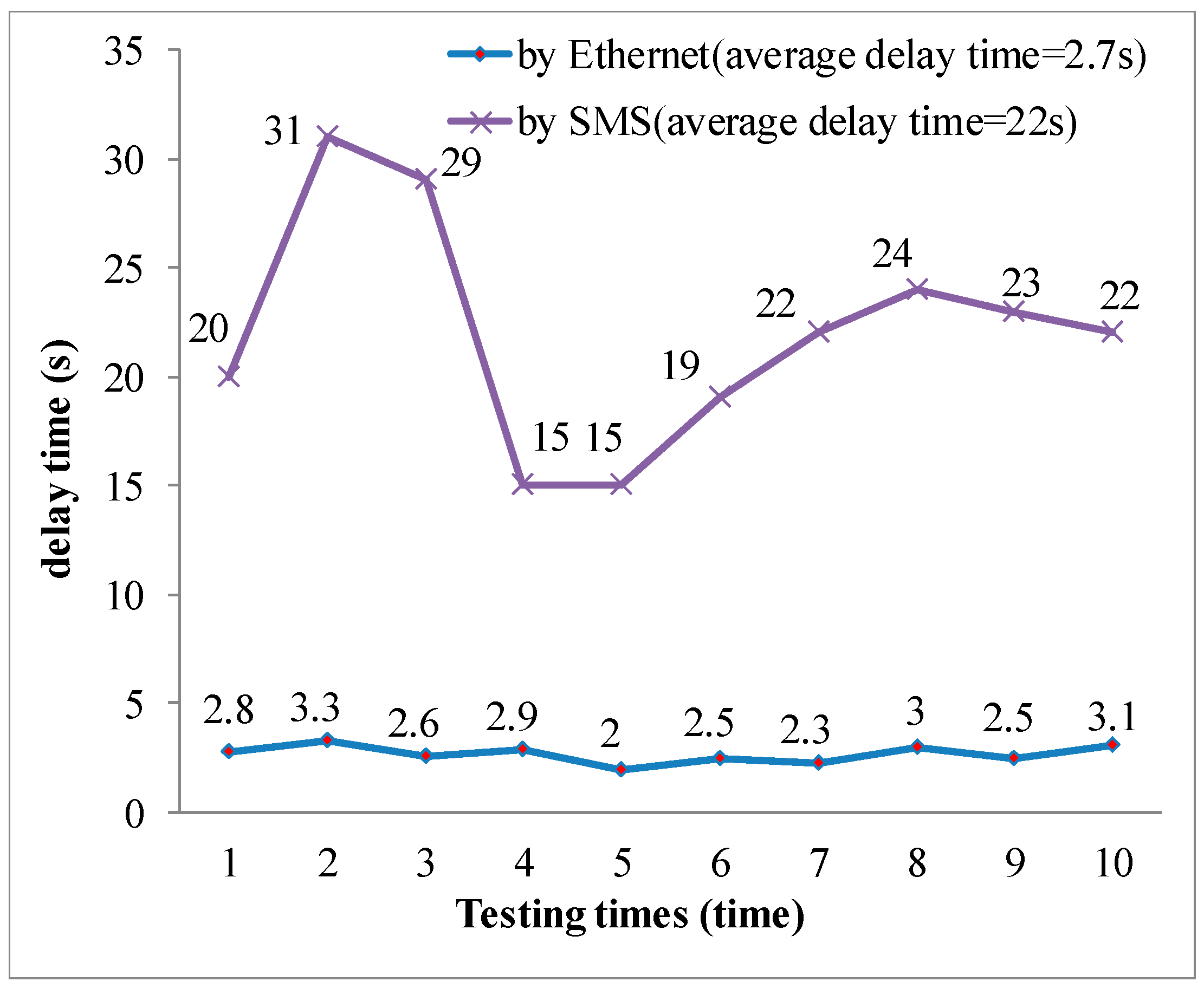
6. Performance Testing and Discussion

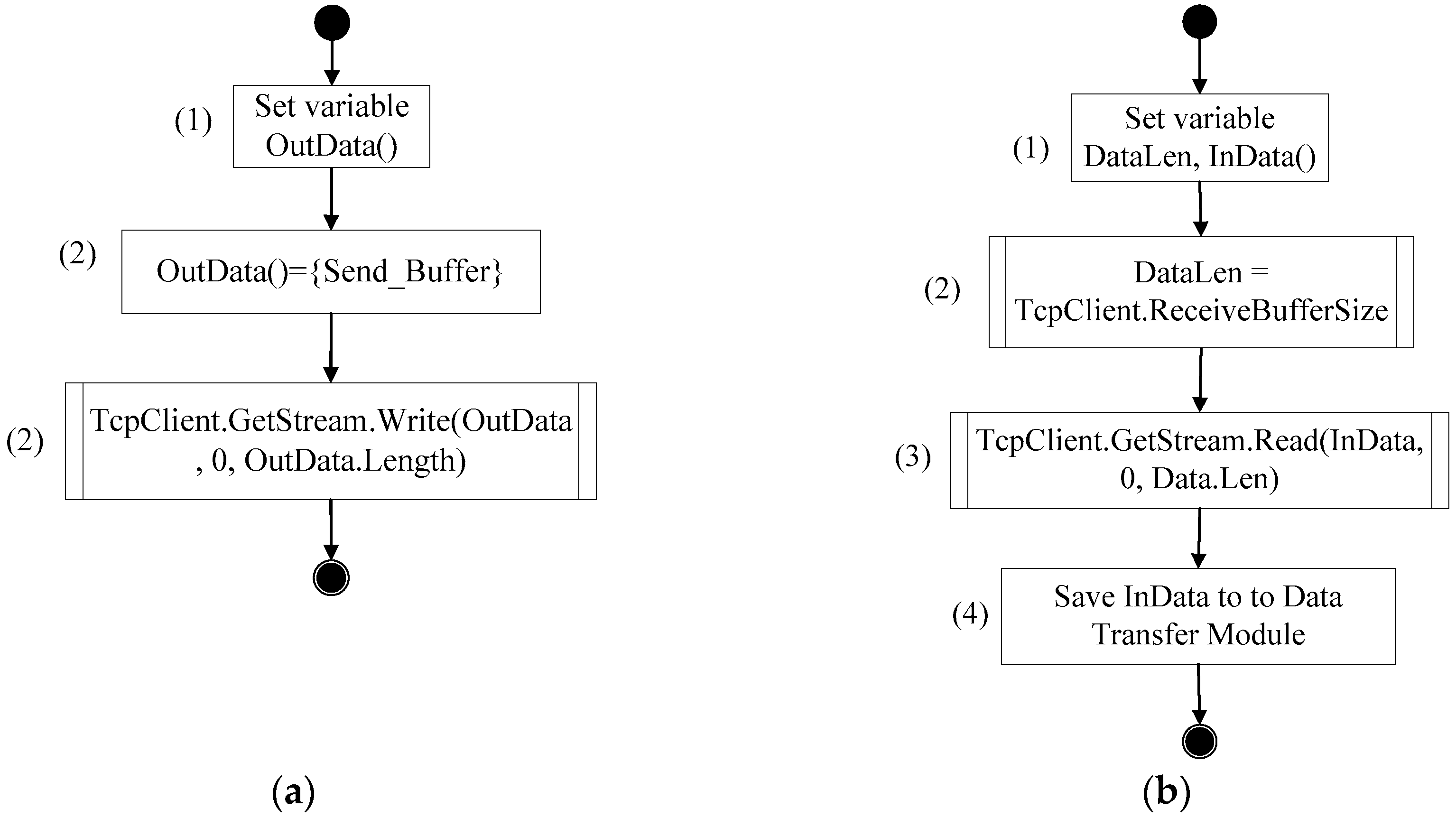
The objective of this test was to compare the delays experienced when transmitting sensor data using the Ethernet and GSM/SMS. The test process was as follows: (1) User commands server to collect sensor data. (2) Server issues data transmission command. (3) Data are transmitted via Ethernet/GSM to the gateway. (4) Gateway system receives the command. (5) WSN is ordered to collect sensor data. (6) Gateway receives data (20 Bytes) from WSN. (7) Data are transmitted via Ethernet/GSM to the server. (8) Server receives and displays data. We conducted testing using the above procedure 10 times. There was a 2.7-s delay when transmitting and receiving data through the Ethernet. However, the average delay time for SMS was 22 s. The test results for communication delay time over Ethernet or SMS are shown in Figure 19.
After reviewing the literature on the operating principles of GSM/SMS, we identified three possible reasons for why we experience longer delays when transmitting data via SMS: (1) Signal quality for mobile phones is determined by the distance from the area being monitored to the nearest mobile phone tower. Also, different cellular antennas may provide different signal and reception quality. (2) Text messages take longer to process. The message from the sender is received and stored by the telecommunications provider in an SMS Management Center (SMC), which must then locate the user details of the desired recipient and finally forward the message. (3) We measured the round-trip transmission delays between Monitoring Server and Gateway Server, so the SMS for longer delays (22 s), but the Ethernet communicating utilized a local area network (LAN), having a short time delay (2.7 s).
In this paper, the abnormal proportion of Ethernet and SMS transmission decreases to zero, thereby using a reliable data collection scheme in consideration of efficiency and management [15].

7. Conclusions

In this study, we designed an embedded gateway with wired/wireless communication capabilities for military warehouse monitoring systems. In addition to extending the communication range of the ZigBee monitoring system, this gateway can also solve the problem of military facilities being located in communication blind spots or lacking cable networks. We tested the ability of the system to monitor the temperature and humidity of a military warehouse in order to verify the effectiveness of the embedded gateway. The results showed that the gateway is capable of automatically switching to communicating via GSM/SMS when the Ethernet connection fails. Data takes longer to transmit when using GSM/SMS, compared to the Ethernet. However, in a scenario where speed of transmission is not a priority and the Ethernet connection has failed, the GSM/SMS functionality ensures that the system remains operational.
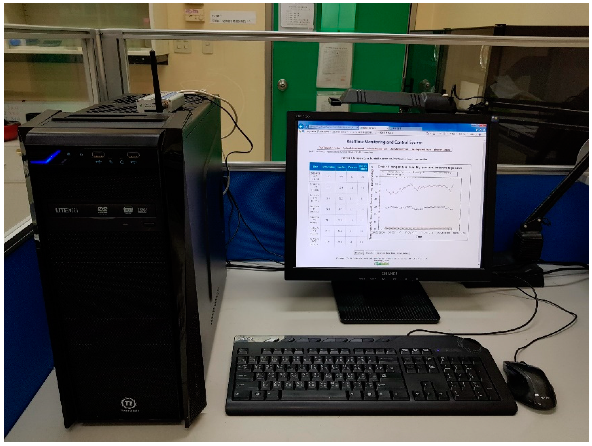
Finally, an embedded gateway with communication extension and backup capabilities for ZigBee-based monitoring and control systems was constructed to monitor the temperature, humidity, and pressure of the weapons in the storage tank at the National Chung-Shan Institute of Science & Technology to validate the feasibility and practicality of the proposed architecture. The results of this research will be a useful reference for developing long-distance or large-scale ZigBee monitoring systems in the future.

Author Contributions

K.-F.L. and S.-S.L. performed the experiments. K.-F.L. and P.-N.C. wrote the manuscript. M.-H.H., C.-H.K. and P.-N.C. provided the concept and experimental design of the study and reviewed the paper prior to submission. All authors discussed the results, analyzed the data and commented on the manuscript.

Funding

This research received no external funding.

Acknowledgments

This study was supported by grants from the Ministry of National Defense-Medical Affairs Bureau (MAB-106-067, MAB-106-068).

Conflicts of Interest

The authors declare no conflict of interest.

References

  1. Joseph, C.; Kishoreraja, P.C.; Reji, M.; Baskar, R. Design of Wireless Sensor Network Gateway for the Internet of Things. Int. J. Pure Appl. Math. 2017, 117, 41–45. [Google Scholar] [CrossRef]
  2. Farella, E.; Falavigna, M.; Riccò, B. Aware and Smart Environments: The Casattenta Project Original Research Article. Microelectron. J. 2010, 41, 697–702. [Google Scholar] [CrossRef]
  3. Sha, C.; Wang, R.C.; Hunag, H.P.; Sun, L.J. A type of Healthcare System Based on Intelligent Wireless Sensor Networks Original Research Article. J. China Univ. Posts Telecommun. 2010, 17, 30–39. [Google Scholar] [CrossRef]
  4. Gund, M.; Andhalkar, S.; Patil, D.; Wadhai, V.M. An Intelligent Architecture for Multi-Agent Based m-Health Care System. Int. J. Comput. Trends Technol. 2011, 1, 157–161. [Google Scholar]
  5. Al Rasyid, M.U.H.; Nadhori, I.U.; Sudarsono, A.; Alnovinda, Y.T. Pollution Monitoring System Using Gas Sensor Based on Wireless Sensor Network. Int. J. Eng. Technol. Innov. 2016, 6, 79–91. [Google Scholar]
  6. Ju, Y.; Bai, Y.; Zhu, Y.C.; Wang, R.S.; Li, Y.K. Hybrid Wired and Wireless Sensor Networks Interconnection. Appl. Mech. Mater. 2013, 380–384, 2226–2230. [Google Scholar] [CrossRef]
  7. Maleki, J.; Sepehri, M.M.; Farvaresh, H.; Nayebi, A.; Sawhney, R. Multi-layer hybrid wired-cum-wireless sensor network design. Int. J. Commun. Netw. Distrib. Syst. 2012, 9, 286–310. [Google Scholar] [CrossRef]
  8. Wei, S.; David, S.; Moshe, L. A Robust Load Balancing and Routing Protocol for Intra-Car Hybrid Wired/Wireless Networks. IEEE Trans. Mob. Comput. 2018, 1. [Google Scholar] [CrossRef]
  9. NCC. Mobile Communications Service Information System. Available online: http://freqgis.ttida.org.tw/Freqgisindex/ (accessed on 1 June 2018).
  10. Digital Cellular Telecommunications System (Phase 2+); Radio Transmission and Reception, ETSI TS 100 910 v8.15.0 (3GPP TS 05.05v8.15.0); ETSI: Sophia Antipolis, France, April 2004.
  11. Anandan, R.; Karthik, B.; Kiran Kumar, T.V.U. Wireless Home and Industrial Automation Security System Using Gsm. J. Glob. Res. Comput. Sci. 2013, 4, 126–132. [Google Scholar]
  12. Olarewaju, I.K.; Ayodele, O.E.; Michael, F.O.; Alaba, E.S.; Abiodun, R.O. Design and Construction of an Automatic Home Security System Based on GSM Technology and Embedded Microcontroller Unit. Am. J. Electr. Comput. Eng. 2017, 1, 25–32. [Google Scholar] [CrossRef]
  13. Requirements for the Control of Electromagnetic Interference Characteristics of Subsystems and Equipment; MIL-STD-461E RE102; Technical Report; US Department of Defense: Washington, DC, USA, 20 August 1999.
  14. Environmental Test Methods and Engineering Guidelines; MIL-STD-810E; Technical Report; US Department of Defense: Washington, DC, USA, 14 July 1989.
  15. Lin, S.S.; Lan, C.W.; Chen, P.N.; Wu, Y.H. A Reliable Data Collection Scheme with Efficiency Consideration for ZigBee Wireless Sensor Network Applications. Sens. Mater. 2015, 27, 773–785. [Google Scholar] [CrossRef]
Figure 1. Signal coverage and reception quality of 3G/4G mobile phone networks.
Applsci 09 00456 g001
Figure 2. Operational schematic diagram.
Applsci 09 00456 g002
Figure 3. Functional design of embedded communication gateway with automatic back-up capabilities.
Applsci 09 00456 g003
Figure 4. Operational cycle of the embedded communication gateway with automatic back-up capabilities.
Applsci 09 00456 g004
Figure 5. (a) Send process; (b) receive process in Ethernet communication.
Applsci 09 00456 g005
Figure 6. The ‘send’ process in GSM/SMS communication.
Applsci 09 00456 g006
Figure 7. The ‘receive’ process in GSM/SMS communication.
Applsci 09 00456 g007
Figure 8. The ‘send’ function of UART communication.
Applsci 09 00456 g008
Figure 9. The ‘receive’ function of UART communication.
Applsci 09 00456 g009
Figure 10. The system implementation architecture.
Applsci 09 00456 g010
Figure 11. WSN monitoring system server.
Applsci 09 00456 g011
Figure 12. Exterior of the smart gateway.
Applsci 09 00456 g012
Figure 13. Interior components of the smart gateway.
Applsci 09 00456 g013
Figure 14. (a) Exterior of the sensor node device. (b) Interior of the sensor node device.
Applsci 09 00456 g014
Figure 15. Control interface for managing sensor timings.
Applsci 09 00456 g015
Figure 16. Scenario 1: real-time tracking of temperature, humidity, pressure, and battery power of Sensor 1.
Applsci 09 00456 g016
Figure 17. Temperature, humidity, pressure, and battery power of Sensor 1 in Scenario 2.
Applsci 09 00456 g017
Figure 18. Real-time tracking of temperature, humidity, pressure, and battery power from Sensor 1 in Scenario 3.
Applsci 09 00456 g018
Figure 19. The testing results of communicating delay time over Ethernet an SMS.
Applsci 09 00456 g019
Table 1. Three test case scenarios.
Case NumberTransmission PathwayIntervalsTotal Test TimeNode Numbers
1Ethernet30 min1 day1, 2
2GSM/SMS30 min1 day1, 2
3Automatic switching between Ethernet and GSM/SMS10 min1 h1
Table 2. Testing the functionality of the smart gateway.
Timing21:0021:1521:4522:00
System StateSystem onEthernet connection fails (system automatically switches to transmitting data via GSM)Ethernet connection recovers (system automatically switches back to transmitting data via the Ethernet)System off
Regular reportingTransmit data on the temperature and humidity of the warehouse every ten minutes.

