Influence of Solvent Selection in the Electrospraying Process of Polycaprolactone


ENSAIT, GEMTEX—Laboratoire de Génie et Matériaux Textiles, F-59000 Lille, France
*
Author to whom correspondence should be addressed.
Appl. Sci. 2019, 9(3), 402; https://doi.org/10.3390/app9030402
Submission received: 4 December 2018
/
Revised: 3 January 2019
/
Accepted: 8 January 2019
/
Published: 24 January 2019
(This article belongs to the Special Issue Synthesis and Application of Microcapsules)
Abstract
:Electrosprayed polycaprolactone (PCL) microparticles are widely used in medical tissue engineering, drug control release delivery, and food packaging due to their prominent structures and properties. In electrospraying, the selection of a suitable solvent system as the carrier of PCL is fundamental and a prerequisite for the stabilization of electrospraying, and the control of morphology and structure of electrosprayed particles. The latter is not only critical for diversifying the characteristics of electrosprayed particles and achieving improvement in their properties, but also promotes the efficiency of the process and deepens the applications of electrosprayed particles in various fields. In order to make it systematic and more accessible, this review mainly concludes the effects of different solution properties on the operating parameters in electrospraying on the formation of Taylor cone and the final structure as well as the morphology. Meanwhile, correlations between operating parameters and electrospraying stages are summarized as well. Finally, this review provides detailed guidance on the selection of a suitable solvent system regarding the desired morphology, structure, and applications of PCL particles.
1. Introduction
Polycaprolactone (PCL), a semi-crystalline polyester, is prepared from ring-opening polymerization of ε-caprolactone monomer under the catalysis of metal anion complex catalyst [1]. Due to its relatively low melting temperature (Tm = 60 °C) and glass transition temperature (Tg = −60 °C), PCL has excellent viscoelastic properties and processability [2,3]. Moreover, PCL is regarded as a green environmental and non-toxic polymer material due to its prominent biocompatibility and biodegradation. Thus, PCL is widely used in medical tissue engineering, drug delivery, and control release systems, food packaging industry, antibacterial study, protective clothing fabrication, and biosensors [4,5,6,7,8,9]. Particularly, micro- or nanoscale PCL particles with a wide specific surface area, a small pore size, high encapsulation efficiency, and a high porosity are considered to be the main candidates in these fields [10,11]. For instance, the release profiles of active drug encapsulated in polymer microspheres are controlled by the size, distribution, and porous structure of microcapsules [12,13,14,15,16].
Meanwhile, the drug-loaded nanoparticles with small size and narrow distribution have an enhanced ability to reach their target [17]. The degradation process of these particles with a huge surface to volume ratio also occurs at a relatively faster rate [18,19]. Apart from the chemical and physical nature of particles, the properties and applications of polymeric particles are mainly determined by their structure and morphology. However, the perfect design as well as control of the structure and morphology of PCL particles and achieving their high encapsulation efficiency according to requirements during their preparation process is still a hot spot and difficult for scientific researchers. In literature, various techniques are reported for the fabrication of micro- or nanoscale PCL particles or capsules with versatile structure and morphology. Conventional methods include emulsification, spray drying, enhanced solution dispersion, phase separation, solvent evaporation, and hot melt techniques [20,21,22,23,24,25]. Although PCL particles with micro- or nanoscale structure and specific morphology can be obtained successfully via these methods, there are still some limitations and drawbacks, including the use and removal of surfactant, complexity of the process, low encapsulation efficiency, time-consuming, wide particle size distribution, particles agglomeration, use and removal organic solvent and the degradation of protein [26,27,28]. Therefore, the applications and developments of these methods in the biomedical field are inefficient and limited.
Electrospraying, a rapidly emerging electrohydrodynamic atomization process, has great potential to overcome these above limitations and drawbacks [29]. In the process of electrospraying, the polymeric solution is polarized firstly due to the applied electric field and then charged droplets is stretched and accelerated into the charged jet by the electrostatic force generated on the surface of droplets. Next, charged jet breakups into smaller charged droplets via Coulomb repulsion forces. After evaporation of the solvent, micro- or nanoscale particles are collected [30].
On the one hand, its experimental device is operational and straightforward steps are easy to carry out. It can avoid the operation of vigorous stirring, the use of chemical additives (i.e., surfactant, electrolyte and catalyst) as well as large quantities of organic solvents. Therefore, the activity and structure of active substance will not be destroyed during the process of electrospraying [31]. At the same time, electrospraying carries out under room temperature and atmospheric pressure, and there is no further drying step required since the solidification of particles occurs instantaneously during electrospraying process. On the other hand, the size of electrosprayed droplets ranges from hundreds of micrometers down to several tens of nanometers, and the size distribution of electrospray droplets is nearly monodispersed [32,33]. Notably, the structure and morphology of electrosprayed particles are effectively controlled and carefully designed by adjusting the operating parameters, solution properties, and experimental device of the electrospray process [34,35]. The latter is not only critical for achieving improvement in the properties of electrospray particles and diversifying of the structure as well as morphology, but it also promotes the efficiency of the process and broadens the applications of electrospray particles. Besides, when PCL is used as shell material to encapsulate active substance via electrospraying, high encapsulation efficiency of the fragile active substance, as well as its protection, and avoiding any particle aggregation attributed to the Coulomb repulsions among charged droplets as well as rapid solvent evaporation during their flight toward the collector [36,37].
Although flashing nanoprecipitation, as a solvent displacement technology, also fabricates polymeric particles in simple and rapid way, the high requirements in the state of working streams (strong turbulence), special micro-mixers and the lipophilicity of active substances make it less feasible compared with electrospraying. For solvent evaporation, on the one hand, the use and removal of surfactant will deteriorate the final structure as well as the properties of particles. Meanwhile, the removal of the organic solvent also takes a lot of effort and time. On the other hand, the size, as well as the particle size distribution, are difficult to design and control. In most cases, particles with broad size distribution are obtained. Therefore, electrospraying is regarded as a green, rapidity and efficient technology to design polymeric microparticles.
During the process of electrospraying, there are lot of interrelated parameters which influence the realization and the outcomes. By controlling these parameters, different structures and morphologies of electrosprayed particles are obtained [38,39,40]. According to their inherent characteristics, these parameters divide into two categories, solution formation parameters, and operating parameters. Solution formation parameters mainly include solvent systems, polymer concentration, polymer molecular weight, and active substance concentration. These solution formulation parameters mainly determine the physico-chemical properties of electrospraying solution (including viscosity, surface tension, vapor pressure, dielectric constant, electrical conductivity, and chains entanglement). Process parameters mainly include applied voltage, flow rate, working distance, spraying mode, nozzle gauge, collection method, environmental temperature, environmental pressure, and environmental humidity. Among these interrelated parameters, the selection of a suitable solvent system as the carrier of PCL is fundamental and a prerequisite for the optimization of electrospraying and controlling the morphology as well as the structure of electrosprayed particles. Firstly, the main solution properties including the surface tension, electrical conductivity, viscosity and vapor pressure depend mainly on the used solvent system [41]. These properties influence the process stability and the formation of Taylor cone during the electrospraying, but also the working range values of operating parameters, i.e., the applied voltage, the flow rate, and the working distance. The formation of Taylor cone during electrospraying is indispensable for stabilizing experimental process and achieving the micronization, nanonization, as well as homogenization of electrosprayed particles [42,43]. It is essential to understand that only in the stable cone-jet mode the size and morphology of electrosprayed particles can be controlled and designed by carefully changing other parameters. Secondly, the size, size distribution, and morphology of electrosprayed particles are also determined by these solution properties and operating parameters. For instance, increasing electrical conductivity of electrospraying solution or applied voltage not only decrease particles size significantly but also broaden the particle size distribution [44]. The entanglement among polymeric chains and the solution viscosity determine the final morphology of electrospraying object, i.e., fibers or spheres. In general, electrolytically sprayed microspheres are manufactured with a low viscosity and a lower polymer chain entanglement, unlike electrospun fibers, which require the use of a solution with a higher viscosity and a higher entanglement amount [45,46]. Besides, the phase separations and the solidification processes of electrosprayed droplets play a primary role in the shape on the morphology of the obtained particles. They are also affected by the physico-chemical properties of electrospraying solution and more especially the system solvent choice used to solubilize the polymer [47,48]. For example, the non-porous and filled PCL particles change into cup-shaped porous particles when acetone is added into the PCL/chloroform electrospraying solution [49].
Meanwhile, the electrosprayed particles with porous structure are easily obtained when the binary solvent system is used. The different evaporation rates, as well as compatibility among non-solvent, solvent and polymeric matrix, lead to the phase separation and result in the synthesis of highly porous particles [50]. Furthermore, the formation of a core-shell structure for PCL capsules and the encapsulation efficiency of active substance are also closely related to the selection of solvents systems [38]. According to these above mentioned, investigating these effects coming from different solvent systems and selecting a desirable solvent system for electrospraying are crucial for designing and obtaining an ideal structure as well as the morphology of electrosprayed PCL particles. However, the understanding of the effect of selecting solvent systems on electrospraying is still limited even though it is widely used to prepare polymeric particles. The selection of a suitable solvent system used in the electrospraying process according to the required structure, properties, and applications of final particles is still unclear.
This paper aims to present a comprehensive review of the current state of the art in preparing micro- or nanoscale PCL particles via electrospraying technology. PCL was selected as a suitable polymeric system due to its biocompatibility, biodegradability, and non-toxicity, and can be considered as one of the main candidates in drug control release and delivery, tissue engineering, and food packaging. Furthermore, the study and the use of the kind of polymer also meet the requirements for green, non-toxic and environmentally friendly production processes as well as technology development. Taking into account its thermal properties, such as its low glass transition and melting temperatures, its solubility characteristics, the design of the microencapsulation process can be optimized. Therefore, the review focuses on the use of different solvent systems and describes the effects of varying solution properties and the operating parameters in electrospraying process, on the formation of Taylor cone and the final structure as well as the morphology. Meanwhile, some relationships among the operating parameters, the formation of cone jetting and final structure as well as the morphology of electrospray particles are also summarized. Finally, this review provides detailed guidance about the selection of a suitable solvent system concerning the desired morphology and structure of PCL particles and their applications in some fields.
2. Electrospraying Technology
2.1. Mechanism of Electrospraying
Electrospraying is a method of liquid atomization that achieves the stretching and breakup of polymeric solution to obtain micro- or nanoscale particles via means of electrical forces [51]. Six types of forces govern the electrospraying process, i.e., (i) gravity of polymeric solution, (ii) electrostatic force generated from external electric field between nozzle and collector, (iii) Coulomb repulsion force among adjacent charged carriers on the surface of jet, (iv) viscoelastic force of polymeric solution, (v) surface tension in the interface between air and liquid, and (vi) frictional force between charged jet and surrounding air (Figure 1) [52,53]. Among these forces, electrostatic force, Coulomb repulsion forces, viscoelastic force, and surface tension affect the stretching as well as atomization of polymeric droplets obviously during the electrospraying process. When polymeric solution flows out of the nozzle, the charge distribution and carried charge quantity on the surface of the polymeric solution will change in varying degrees (some extent) according to its electrical conductivity and dielectric constant because of the polarization effect coming from the external electric field. At the same time, initially, the uncharged liquid becomes charged jet and is further stretched towards the direction of electrostatic attraction. However, compared to gravity and electrostatic force that accelerates the moving and stretching of polymeric solution from the nozzle to the collector, the surface tension and viscoelastic ones prevent this moving and elongation because of their opposite behavior on the electrosprayed solution. When these forces reach a balance at a certain range, the droplets at the tip of the nozzle are stretched from the spherical surface into conical surface [54]. In 1964, Taylor proposed, for a perfectly conducting liquid, a first explanation of the conical shape formation, corresponding to a hydrostatic balance between electrostatic forces and surface tension [55]. The presence of the conical surface at the tip of the nozzle during electrospraying is also called Taylor cone. According to Rayleigh’s theory, when the charge quantity distributed on the surface of droplets reaches the value range between 50% and 80% of the Rayleigh limit (Equation (1)), the breakup and fission of charged droplets will occur due to Coulomb repulsions among charged droplets beyond the binding force coming from surface tension that held the droplets together [56]. The aggregation among electrosprayed particle is depressed during their flight from the nozzle to collector due to Coulomb repulsions, to induce the formation of tiny solid particles after solvent evaporation.
where , , , and are the charge quantity of Rayleigh limit, the dielectric constant of the medium surrounding the droplets, the surface tension of electrospray liquid, and the diameter of droplets, respectively.
The formation of a Taylor cone and the fission of charged droplets are crucial for preparing PCL particles with idea structure as well as morphology via electrospraying. On the one hand, the size of the electrosprayed particles can be dispersed into micrometer or even nanometer range by the Coulomb repulsions, and the mono-dispersion of particles is obtained under cone-jet mode. On the other hand, the effective design and control of the structure, as well as the morphology of electrosprayed particles and the process reproducibility is achieved easily under cone-jet mode due to its stability and continuity. The effects of various parameters on the formation of the Taylor cone as well as the breakup of the charged droplets have been the topics of several research projects [57,58,59,60]. The spray mode changes gradually from dripping mode to cone-jet mode with increasing the applied voltage. Then, the spray mode is further transmitted from stable cone-jet to multi-jet mode (unstable cone-jet mode) when the applied voltage beyond a certain range [61]. Therefore, a suitable applied voltage to reach a balance among electrostatic, viscoelastic forces and surface tension in a droplet at the tip of the nozzle is required for achieving the cone-jet of the electrospraying solution. The value of working distance from nozzle to collector also affects the formation of Taylor cone and the breakup of the charged droplets via changing the strength of electric field. According to Smeets et al. [62], the achievement of a stable cone-jet rises with the use of a lager tip-to-collector distance and smaller flow rate. Apart from operating parameters, the success of stable cone-jet and the breakup of droplets are also closely related with the physical properties of electrospraying solution [63,64,65]. The value of electrical conductivity of electrospraying solution affects the charge quantities on the surface of droplets and further influences the strength of electrostatic force. Several authors have concluded that cone-jet mode was obtained in air only if the electrical conductivity of the liquid was set in a certain range [66,67]. As for the upper limit, Mutoh et al. [68] have found that jet changes from a permanent to an intermittent jet, when the conductivity of the solution beyond than 10−5 S/m. For lower limit, estimates generally vary between 10−8 and 10−10 S/m. Besides, the range from the upper and lower limits of conductivity broadens when the solution has low surface tension.
On the one hand, if the surface tension is too high, the formation of the Taylor cone at the tip of the nozzle is maintained due to the change in spherical shape of the liquid. On the other hand, corona discharge results from excessively high surface tension at the tip prevent the electrostatic atomization of charged droplets [69]. According to Smith et al., the atomization of charged droplets in cone-jet mode cannot be achieved if the surface tension of electrosprayed liquid exceeds 50 mN/m [70]. The upper limit of the surface tension of the solutions varies, according to the properties of solute and solvent, and the operating parameters of the process. Furthermore, the viscosity of the solution needs also to be considered, since it influences the formation of cone-jet. Some researchers concluded that the solution with higher viscosity is efficient to maintain the cone-jet mode during the electrospraying process [71,72].
These relationships among operating parameters/solution properties and the characteristics of electrospraying (including jet’s diameter, droplet size, and emitted current) are also calculated quantitatively by scaling laws [73,74]. In 1994, de la Mora et al. firstly proposed emitted current () scaling law (Equation (2)) and jet’s diameter () scaling law (Equation (3)) based on the electrospraying of some pure organic solvents with high conductivity and low viscosity [75]. Meanwhile, the scaling laws of droplet size () (Equation (4)) as well as emitted current (Equation (5)) of non-polar organic solvents were also calculated [76].
where , , , , and are electrical permittivity of a vacuum, surface tension of solution, density of solution, electrical conductivity of solution, dielectric constant of solution and flow rate of electrospraying liquid, respectively. , and are special constants determined by self-solvent properties [66,77,78,79].
The scaling laws of emitted current (Equations (6) and (8)) and diameter of the jet of organic solvents with viscosity (Equations (7) and (9)) were further proposed by Ganan-Calvo et al. in 1996 [77].
As for high viscosity solution ():
As for low viscosity solution ():
where , , , , and are the liquid–gas surface tension, vacuum electrical permittivity, liquid density, liquid flow rate, liquid viscosity, and liquid electrical conductivity, respectively.
The changes in trends of emitter current, as well as the jet diameter (or droplet size) with the changing of flow rate (or conductivity, surface tension), are similar not only between high conductive and high viscous solvents but also between low conductive and low viscous ones. Ganan-Calvo et al. concluded more precise scaling laws about emitted current and droplets size for two different solutions (low viscosity as well as low conductivity solvent and high viscosity as well as high conductivity solvent) [80]. Finally, a general and unified description about scaling laws related to various parameters for the emitted current and droplet size under different boundaries was given [73].
The scaling laws allow obtaining a deeper and complete understanding of the electrospraying mechanism based on the influences of the solution properties and operating parameters. Thus, according to the experimental situation, the selection of the appropriated theoretical approach predicts the formation of the cone-jet mode and provides a theoretical guide for the design of the structure and the morphology of electrosprayed droplets by modifying the properties of the solution [81,82]. Yao et al. found that the spray current (I) follows the scaling laws of the flow rate (Q) of the polymeric solution are found to be as well as the droplet size () scaling laws one [58]. Besides, Hogan et al. also concluded that an appropriate scale law predicts the size of polymer particles produced from the polymer volume fraction and the operating parameters of the electrospraying process [43]. From these laws of scale, the efficiency of the control and design of the structure, and the morphology of the polymer particles during the electrospraying process can be optimized by modifying the solution properties, such as the solvent system and operating parameters.
Also, when scaling laws are used to analyze the process and outcomes of encapsulating active substance via coaxial electrospraying of the polymeric solution, the physical properties of inner and outer liquids need be considered at first. The emitted current mainly depends on the flow rate of the driving liquid, which has higher electrical conductivity. López-Herrera et al. found that its dependence on the flow rate of driving liquid fits well the law in the process of coaxial electrospraying [72]. Meanwhile, Marín et al. concluded that the relationship between the diameter of the outer jet and the flow rate of the outer liquid follows the scaling law [83]. The relation between the droplet size and the liquid flow rate (), depends on the viscosities and electrical conductivities of inner and outer liquid solutions. When, the first one has a higher viscosity, and the second one a higher electrical conductivity, the droplet size scales linearly with the flow rate of inner phase and the flow rate of the outer one. For a higher electrical conductivity of the inner liquid coupled to the higher viscosity of the outer one, the breakup process of working solutions mainly depends on the value of .
On the one hand, an increase in this ratio leads to an increase of the shell materials, whereas its decrease may achieve uniform coverage of the tiny dispersed droplets. On the other hand, the obtention of a core-shell structure is related to the physical properties of the working solutions, and the flow rates used. Thus, according to Mei et al., the core-shell structured droplets are only formed when the ratio of charge relaxation lengths of the inner and outer liquids () is less than 500, and the ratio of inertial breakup lengths of inner and outer liquids () is less than 0.015 [84]. Furthermore, some authors concluded that the cone-jet of inner and outer liquids is achieved when (1) the flow rate of the outer liquid is higher than that of the inner one, (2) the outer liquid has higher viscosity and lower electrical conductivity, and (3) the surface tension of the core solution is higher than that of the shell solution one [85,86].
The porosity of the structure can also be controlled and designed via electrospraying. During the flight process of charged droplets from the nozzle to the collector, the evaporation of the solvents leads to the solidification of the particles. This last phenomenon is also affected by many factors, including boiling point of solvents, environmental conditions (temperature, humidity, and pressure) and collection method and so on. Therefore, the phase separation process can be controlled to obtain polymeric particles with different porous structures and morphologies, to be used in various application fields.
2.2. Experimental Apparatus
In general, the setup of electrospraying mainly composes by syringe, syringe pump, nozzle, high-voltage generator, and collector (Figure 2a). In order to facilitate observation and analysis, light source and high-resolution camera connected with a computer are also often used in the process of electrospraying [38]. At first, electrospraying solution is added into a syringe and further transported to the nozzle under an adjustable flow rate via syringe pump. The nozzle is linked with one end of the high-voltage generator (mostly positive), and the other end of the high-voltage generator is connected to the collector (often grounded or more rarely negatively charged). The distance between the tip of the nozzle and collector usually range from a few centimeters to several tens of centimeters. Due to the strong electric field between nozzle and collector and the Coulomb repulsions, the electrospraying solution will be stretched and further dispersed into smaller droplets, which are ejected from the tip of Taylor cone. During the flight of droplets to the collector, solvents in these droplets will evaporate, and solid particles can be obtained in collector finally. Further, if needed, these particles could be placed into a vacuum oven to remove the residual solvent. Sometimes, in order to further stabilize the process of electrospraying and cone-jet, a ring-shaped electrode is placed between the nozzle and the collector [87,88]. The strength of electric field between the nozzle and ring-shaped electrode and the strength of electric field between ring-shaped and collector can be effectively adjusted via controlling the distance among them. Meanwhile, the size and distribution of electrosprayed particles will change obviously with the changing of the electric field among nozzle, ring-shaped electrode, and collector.
With increasing demands for diversified structures of polymeric particles in the biomedical field, there are some changes and innovations in the setup of electrospraying to prepare polymeric particles with novel structure and morphology for satisfying these demands. Major innovations and changes focused on the structure of nozzle and collection method. According to the position of the capillary in the nozzle, the nozzles used in electrospraying divide into two categories, coaxial-capillary nozzle, and parallel-capillary nozzle. Common coaxial-capillary nozzles include two or three capillaries coaxial nozzle (Figure 2b,c). Single-shell capsules and double-shell capsules can be fabricated by using these nozzles in electrospraying. The core material is added into the inner capillary and shell material is added into the outer capillary. A separate syringe pump controls the flow rate of liquid in each capillary. As for parallel-capillary nozzle, it consists of some parallel inner capillaries and an outer capillary (Figure 2d). Jiang et al. first time adopted these nozzles to prepare a single microcapsule with multiple active substances embedded [89]. They found that each component in microcapsule is inhibited into individual compartments free of contact with others. If two active substances in microcapsules need to be mixed, the nozzle with static micromixer (Figure 2e) can be used during electrospraying. Wu et al. have used this nozzle to fabricate QD605/Cy5-G3139-loaded lipoplexes with high compatibility, high encapsulation efficiency, highly uniform and fine size [90]. Besides, in order to improve the throughputs and productivity of electrospraying, some special nozzles (Figure 2f,g) are also used in electrospraying to achieve the stable multi-jet [65,91]. Using grooved inner nozzle can not only strengthen the electric field at the groove but also promote the formation of Taylor cone at each groove. Therefore, the stable multi-jet that ensures the desired size and uniform dispersion of electrosprayed particles can be successfully achieved, and the throughputs, as well as the productivity of electrospraying, also enhance significantly. Meanwhile, the interactions between inner and outer liquids and its interference in the formation of cone-jet can be optimized and minimized when the inner capillary is extended some distance out from the outer capillary. Similar results are also obtained using multiplexed electrospray device with several electrospraying sources operating in parallel and an extractor. The extractor not only minimizes interference between sources but also localizes the electric field.
A grounded metal plate (usually an aluminum foil) is mainly used to collect electrospraying particles, and sometimes a glass slide is also placed on the metal plate. Although these collection methods are convenient and straightforward, there are still some drawbacks. For example, the solvent with a high boiling point is challenging to be removed out when droplets reach the surface of the collector. These particles with residual solvents trace tend to aggregate together to form large droplets. Meanwhile, the collection efficiency of metal plate or glass slide is relatively low due to the airflow and long flight distance. The majority of the electrosprayed particles is carried away by the airflow and cannot reach the surface of the collector, then finally deposited on the other place of working cupboard. In order to prevent the aggregation among electrosprayed particles and improve the collection efficiency, a grounded bath containing liquid media (Figure 2i) and an enclosed chamber with air/nitrogen flow and filters (Figure 2h) are applied to collect electrosprayed particles. The selection of collection liquid media mainly depends on its chemical interactions with the particles (including core and shell material), compatibility to solvent systems in electrospraying solution, and surface tension [95].
Thus, this system requires a poor chemical affinity between the liquid media to the polymeric shell and core substance, to achieve complete entrapment of it under microsphere or microcapsule form. The compatibility between collection media and solvent system in electrospraying solutions need to be higher than that between polymeric matrix and solvent system. The residual solvent in particles diffuses into collection media and is effectively removed from particles due to the existence of a concentration gradient. The aggregation of electrosprayed particles can be further prevented with the use of a low surface tension collection solution. The main disadvantages of this collection method are that (1) the drug or active substance absorbed on the surface of particles may diffuse into the collection media, and (2) these collected particles tend to form a film at the surface, which hampers their further dispersion. In addition, some researchers also put some aqueous solution containing a polyelectrolyte into the bath [96,97]. The use of air/nitrogen flow with vacuum aspiration as well as filters in a chamber allows to increase the collection yield and to obtain particles with a smooth surface state and low mean diameter, due to sufficient evaporation time of solvent [94]. In some cases, ring-shaped grounded copper wire was also applied to collect the electrosprayed particles, having a uniform size and a smooth surface. This method has a higher collection efficiency compared with other collection methods [98].
3. Selection of Solvent Systems Used in PCL Electrospraying
PCL, as a biocompatible, biodegradable, and semi-crystalline polyester, is widely used in the fields of medical tissue engineering, drug delivery, control release systems, food packaging, antibacterial study, protective clothing fabrication, and biosensors. Particularly, the drug-loaded PCL microspheres or other active substances encapsulated by PCL shell obtained from electrospraying have more potential and advantages in these fields. The selection of a suitable solvent system to prepare PCL electrosprayed solution is one of the main points to take into account since it influences not only the physico-chemical properties of the working solutions, but also the characteristics of the obtained particles such as the mean diameter, size distribution, structure, and morphology. Furthermore, the formation of the Taylor cone, the breakup of electrosprayed droplets, and the solidification step of the particles depend also on the solvents system. Therefore, among the various criteria, three of them are mainly considered, i.e., (i) it needs at least partially solubilize PCL, (ii) the obtained physico-chemical properties of the solution (surface tension, electric conductivity, viscosity, vapor pressure, boiling point, and dielectric constant) should be suitable to achieve a cone-jet mode; and (iii) the selection of solvent systems should take into account the desired structure and morphology of final PCL particles.
3.1. Hansen Solubility Parameter
The Hansen Solubility Parameters (HSPs) methodology is one of the approaches used to design the formulation system with PCL. Bordes et al. have determined the three partial solubility parameters of PCL by the group contribution method, swelling experiments, and turbidimetric titration [99], whereas Huang et al. have used [100] the experimental results obtained by Tian and Munk by inverse gas chromatography [101]. The values change according to the molecular weight of the PCL used, its concentration, and the working temperature (Table 1). Thus, for fixed molecular weight or concentration, the dispersive component decreases, whereas its polar and hydrogen ones increase with increasing the concentration or molecular weight. The value of RS, which depends on the number of appropriate solvent systems to dissolve the PCL, decreases with increasing molecular weight by keeping the concentration at a constant value. Nevertheless, the changes of RS are relatively low with the increase in concentration for fixed molecular weight. Thus, the solubility of PCL in a solvent system depends mainly on its molecular weight and the working temperature, since its partial solubility parameters decrease with its increase.
The PCL Hansen solubility parameters of common solvents are given in Table 2. Good solvents are those which have partial solubility parameters close to PCL ones and a distance lower than the RS value. The reading of the table global approach needs to be confirmed from an experimental point of view. Indeed, there are also two types of exceptions, i.e., (i) solvents, such as acetic acid, benzyl alcohol and 2,2,2-Trifluoroethanol, have a higher distance from PCL is than the RS of solubility sphere, but solubilize PCL, and (ii) several solvents with a distance from PCL less than the RS, cannot solubilize PCL.
Also, the distance between solvent and PCL also characterizes the compatibility as well as interactions between them. A small distance indicates that the compatibility and interactions between solvent and PCL are strong. Thus, the entanglements between the PCL molecular chains, are suppressed, due to the changes in PCL–PCL interactions by PCL-solvent ones. The amount of entanglement influences the morphology and size of the resulted product during the process of electrospraying, either fibers or spherical droplets [46].
A higher entanglement among PCL chains indicates that the molecular structure of PCL chains is more condensed in electrosprayed droplets, and the size, and the morphology of the resulted particles are smaller and smoother, respectively. For the lower entanglements among PCL chains, the molecular structure of PCL chains is loose, and the morphology of the final products is porous (or wrinkled) [92]. Therefore, the distance from solvent to PCL is an indication of the solubility of solvent to PCL and influences the morphology and structure of electrosprayed particles. In can also be noticed that a high solubility is required to obtain high electrospraying productivity, whereas a partial solubility is used for electrospinning process [120].
Binary or ternary solvent system is also used to dissolve PCL for an electrospraying process. It exhibits greater potential and advantages in electrosprayed polymeric particles to provide adequate structure and morphology [121,122], such as a porous morphology [49]. The use of a second solvent, solubilizing partially or poorly PCL, requires the adjustment of its volume fraction in the whole system to fit with the Hansen solubility parameters of the binary solvent system, and therefore ensuring the good solubility of PCL. According to Luo et al. [123], the proportions of the solvents mixed were determined geometrically based on the Teas graph using a method similar to the lever rule. The solubility results of mixed solvents using this method were compared with predictions drawn from the Teas graph. After that, the corresponding Hansen solubility parameters of binary solvent systems can also be calculated by this lever rule. The other criteria to consider are based on toxicity and environmental. For example according to the direction of REACH (Registration, Evaluation, and Authorization of Chemicals) and the regulation of European Pharmacopoeia, anisole, acetic acid, and ethyl acetate are nontoxic and good solvents for dissolving PCL [99].
3.2. Solution Properties for Cone-Jet in PCL Electrospraying
The physico-chemical properties of the electrospraying solution depend on the properties of the solvent system, i.e., (i) electrical conductivity, (ii) surface tension, (iii) viscosity, (iv) vapor pressure, and (v) dielectric constant. The control of these characteristics allows the formation of the Taylor cone, which leads to the production of particles having a low mean diameter and narrow particle size distribution.
3.2.1. Electrical Conductivity
During electrospraying, due to the electrostatic force generated from the applied electric field, the solution is stretched and accelerated into a jet from the tip of the nozzle to the collector. The formation of the Taylor cone occurs at the tip of the nozzle, when a balance among six forces, including gravity, electrostatic force, Coulomb repulsions, viscoelastic and frictional forces, and surface tension, is achieved (Figure 1). The strength of the electrostatic force and Coulomb repulsion acting on electrosprayed droplets mainly depend on the amount of polarization charge in droplets and the strength of the applied electric field. The amount of polarized charges on the surface of the droplets is closely related to the range of the electrical conductivity of working solution in the electric field. The surface tension and viscoelastic forces are counteracted by the electrostatic attraction under the electric field, leading to the formation of the Taylor cone. If the electrical conductivity of the working solution is too high, the Coulomb repulsions among charged droplets increase, as well as the breakup of charged droplets. All these phenomena contribute to modify the balance among the six forces, and the stable cone-jet change to an unstable jet. On the other hand, an excessively low electrical conductivity leads to insufficient electrostatic attractions on the droplets to match with the surface tension and viscoelastic forces of the working solution. Thus, the Taylor cone at the tip of the nozzle is not achieved, nor is the formation of particles.
According to Jaworek and Xie et al. [124,125], the electrohydrodynamic process is carried out under cone-jet mode when the electrical conductivity of working liquids are in the range of 10−11 to 10−1 S/m. Nevertheless, for PCL it ranges from 8.0 × 10⁻¹⁰ to 3.2 × 10⁻² S/m, and more specifically from 10−4 to 10−8 S/m (Table 3). It can also be noticed that it increases with the increase of surface tension and the viscosity of working solutions. Furthermore, a high PCL concentration requires high electrical conductivity of solvent systems. In some cases, if the surface tension and viscosity of the working liquids are too high, an electrical conductivity of working liquids, exceeding the mentioned range, is needed to balance the surface tension and viscoelastic forces in order to achieve the cone-jet mode.
In the use of a coaxial electrospraying, the formation of cone-jet at the tip of the nozzle is also closely related to the electrical conductivities of inner and outer liquid phases [72,131]. On the one hand, for a higher electrical conductivity of the inner liquid than the outer one, the free charges are located at the interface. In this case, inner liquids regard as the driving component and dominate the formation of the Taylor cone. Then, inner droplets are stretched into the conical shape due to the electrostatic forces acting on their surface, which leads to the transfer of the free charges to the surface of the outer phase. Finally, the formation of the Taylor cone of the outer liquid is done when the electrostatic attractions acting on the surface of outer liquid counteract the viscoelastic forces and surface tension (Figure 3a).
On the other hand, a higher the electrical conductivity of the outer phase leads to the distribution of the free charges on its surface. The outer liquid dominates the formation of cone-jet of this configuration. In the first step, it is stretched into the Taylor cone due to the electrical attractions acting on its surface. The Taylor cone formation is only reached when the viscosity of the outer liquid is higher than the inner phase one (Figure 3b).
According to Mei and Zhang et al. [38,84], the cone-jet during coaxial electrospraying is easier to form in the case of inner driving, where the electrical conductivity of the outer liquid is less than that of the inner liquid. This principle is also applied to three-needle or four-needle coaxial electrospraying. To obtain suitable electrical conductivity, some authors reported the addition of metal oxide or high electrical conductivity solvents in the working solutions.
3.2.2. Surface Tension
The surface tension of the working solution affects the formation of the Taylor cone at the tip of the nozzle during the electrospraying process. According to Cloupeau and Smith [69,70], the value of surface tension of the electrosprayed solution cannot exceed 50 mN/m, even if some papers report the use of glycerine (63 mN/m) or water (72.8 mN/m) to achieve it [132,133]. Thus, the low surface tension of the PCL solutions, ranging from 22.5 to 32.8 mN/m (Table 3), allows Taylor cone formation. Furthermore, liquids with a high surface tension trigger also a corona discharge at the tip of the nozzle, which change the stable cone-jet into an irregular spraying and an asymmetrical mode.
In the coaxial mode, when the surface tension of the inner phase is higher than the outer one, the formation of a stable Taylor cone is possible, which leads to the formation of core-shell particles as described by Loscertales et al. [85]. The relations between the surface and interfacial tensions to promote the formation of a cone-jet mode have been studied in details by Mei et al. [134] (Figure 4), with the use of the spreading coefficients () (Equation (10)).
where 1, 2, and 3 represent core liquid, air, and shell in the liquid state, respectively. , and are the surface tension of shell and core liquid, and the interfacial tension between core liquid and shell liquid phases, respectively.
The thermodynamic conditions of the system required for the formation of a complete engulfing are S3 > 0, S1 < 0 and S2 < 0. In other cases, partial or non-engulfing are obtained, due to the presence of unstable cone-jet. Therefore, the core substance or inner phase needs to have a high surface tension value to promote the formation of cone-jet, and after that, a core-shell structure via a coaxial electrospraying process [135,136,137]. To succeed in the design of the electrospraying methods with three-needle or four-needle coaxial, the authors preconize the choice of solvents having similar surface tensions, or close to the dispersed active substance one [93,129,138]. Surfactants or protective colloid may also be added to the various phases until to reach the desired surface properties of the working solutions [139,140].
3.2.3. Viscosity
The viscosities of the electrosprayed solutions influence the formation of a stable Taylor cone, where the direction of the viscoelastic force is opposite to those of gravity and electrostatic attraction ones. On the one hand, the combined viscoelastic force and surface tension are too weak to counteract the gravity and electrostatic attraction ones in a low viscosity medium, leading to a dripping mode rather than a cone-jet one. On the other hand, the use of high viscosity working solutions prevents the formation of stable Taylor cone. The drying of the polymeric particles with the solvent evaporation during the process occludes the tip of the capillary; and therefore limiting the stability of the Taylor cone [86,141]. Thus, there is an appropriate range in viscosity of solution for achieving cone-jet mode during the electrospraying process (Table 3). The viscosity ranges from 1.5 to 5500 mPa·s [62]. An increase of the solution viscosity leads a decrease to the distance from the exit of the nozzle to the apex of the cone. In general, a long distance from the tip of the nozzle to the apex of the cone induces an increase in jetting diameter at the tip of the cone and may lead to dripping mode or spindle mode. An increase in the solution viscosity allows obtaining a cone angle close to the theoretical value of Taylor cone (about 98.6°), which reduces the mean diameter of the obtained particles and narrows its size distribution [142]. For a coaxial process, the formation of the Taylor cone is favored, when the viscosity of the outer phase is higher than the inner one. In this case, its formation for the inner phase is driving by the interfacial interactions and related viscosities diffusion.
3.2.4. Boiling Point
The formation of Taylor cone during electrospraying is also affected by the boiling point of working solution. The solvent evaporation in jetting occurs at the same time that the formation of Taylor cone at the tip of the nozzle. A too low boiling point or high vapor pressure value modify the shape of the cone-jet to change it in an unstable mode. Furthermore, it leads to the drying of the polymeric particles inside the tube or at the tip of the nozzle, until to stop the process. Therefore, the Taylor cone formation is promoted with high boiling point solvent, and is especially useful for high PCL concentrations.
3.2.5. Dielectric Constant
To date, few papers have studied the effect of dielectric constant on the process and outcomes of the electrospraying method. The effects of the dielectric constant on the cone-jet are similar to the electrical conductivity ones. Too high or too low dielectric constant is not conducive to achieving the cone-jet during PCL electrospraying process. Some research works published about the electrospinning of polystyrene noticed that the yield of productivity was correlated to the dipole moment and the dielectric constant of the working solutions [143,144]. Thus, based on the use of 18 solvents to prepare the working solution, it was concluded that the formation of the cone-jet was related to the use of solvent solution having high electrical conductivity and dielectric constant, moderate viscosity, surface tension, and boiling point.
3.3. Solution Properties for Tailoring Characteristics of Electrosprayed PCL Particles
The fission and solidification processes of electrosprayed droplets are also closely related to the physical and chemical properties of the working solutions. Therefore, the morphology, size, and size distribution of obtained particles from electrospraying are affected and determined by the properties of the working solution. Thus, understanding of the relationships between the solution properties and the structure, morphology of the electrosprayed makes it possible to select the suitable solvent systems for the electrospraying process.
3.3.1. Droplets or Fibers
Electrohydrodynamic methods are divided into two categories having the same processes and mechanisms but differ in the obtained morphologies (spherical and fibrous materials), i.e., electrospinning and electrospraying processes. The generation of materials with different shape mainly depends on the fission process of the charged droplet, and more especially on the strength of the intermolecular interactions between macromolecular polymeric chains. Fiber shape is obtained with strong interactions since they stabilize the charged jet and match the Coulomb repulsions of the charged droplets. The polymeric solution is further stretched, and the solvent evaporation leads to the formation of ultrathin fibers [145]. The formation of tiny particles is promoted by the presence of low interactions and strong Coulomb repulsions. Thus, the extent of intermolecular entanglement among PCL chains in working solution is one of the main factors governing the resulted shape [95]. Limited polymeric chain entanglements in the system represent a key parameter to achieve particle morphology by electrospraying according to Shenoy et al. [46]. The degree of entanglement per chain in the electrosprayed solution () is obtained from Equation (11).
where is the polymer volume fraction in the electrosprayed solution, and are the average molecular weight of polymer and entanglement molecular weight, respectively.
The number of entanglement per chain, (), and the critical chain overlap concentration, , corresponding to the crossover concentration between the dilute and the semi-dilute concentration regimes or the concentration inside the radius of gyration of every single macromolecular chain [45], influence the obtained morphology of the final material. Thus, for () ~ 2.5 (1 entanglement per chain), or a polymer concentration less than 3, the process leads to the formation of spherical particles. The increase of () up to 3.5 or the use of a polymer concentration >3 allow having the entangled regime and therefore obtained in the first step a beaded-fiber structure, which evolves in fiber shape morphology. The entanglement is also related to the molecular weight of the polymer used [98] (Figure 5). Thus, the use of PCL with a molecular weight between 10,000 and 45,000 g/mol and a concentration of 9 to 30% by weight leads to the formation of spherical particles. At higher molecular weights, fibrous morphology is preferred, and when it reaches 80,000 g/mol, even working at a relative low concentration, from 0.5% to 10% by weight, ultrafine fibers are also obtained.
Besides, the degree of entanglement of the polymer chains of the electrosprayed solution is also related to the nature of the solvents used. Thus, intermolecular tangles are of two kinds, i.e., (i) interactions between solvents and molecular solutes, (ii) intermolecular tangles between macromolecular chains. The calculation of the parameter (D) is used to guide the approach, since a low value illustrates a good solubility of the polymer in the solvent and a low degree of entanglement among macromolecular chains, while the latter increases with the increase in D. Therefore, spherical particles may be obtained by selecting a polymer/solvent system with a low value of D, while matrix or fibrillar structures resulting from a higher entanglement and therefore a higher value of D or a partial solubility of the polymer in the system. According to Qin and Liu, and Luo et al., with a fixed PCL concentration, the use of solvents such as 1-methyl-2-pyrrolidone, formic acid and N, N-dimethylformamide, in which the solubility of PCL is partial, results in smooth and uniform fibers [120,146]. On the other hand, the use of solvents that perfectly solubilize PCL such as toluene, chloroform, dichloromethane, and tetrahydrofuran leads to the formation of beaded structures or spherical particles.
3.3.2. Particle Size and Size Distribution
Size distribution of particles increases with increasing polymer concentration and/or polymer molecular weight, related to an increase in the solution viscosity, and a decrease in conductivity. It was also expected that at low polymer concentration, the changes in concentration have more variation in viscosity compared with conductivity. At high concentration, the viscoelastic forces in the droplets are opposed to those of Coulomb repulsion to prevent droplet break-up, resulting in the formation of bigger particles. Thus, the increase in PCL concentration from 0.5 to 6 (wt.%) induces an increase in particle size according to Xie et al. (Table 4) [147]. When PCL concentration increases further, to 9.6%, PCL particle size decreases as observed by Bock et al. (Figure 6) [95]. In their work, Ghanbar et al. studied the effect of the variation in the molecular weight of PCL (from 10,000 to 45,000 g/mol) at various concentrations in toluene [126]. They found that changes in formulation parameters leading to an increase in the viscosity of the solution also lead to an increase in size. Some researchers have also reported that working with very low polymer concentrations, weak viscosity makes the process unstable and therefore particle size increase. Besides, at higher concentration, the observed decrease in conductivity leads to an unstable cone jet and therefore an increase in size particle distribution. Besides, the increase in viscosity also results in a decrease in jet diameter [148], which can be correlated with a lower mean droplet diameter during the rupture process according to Cloupeau et al. and Ganan-Calvo et al. [66,69,74,76].
The surface tension of the electrospray solution influences the breakage of the charged droplets and thus the final particle size. Indeed, the particle size increases with decreasing surface tension [92]. According to Midhun et al., the use of higher concentrations of PCL produces larger particles due to increased surface tension [128]. However, during the electrospraying process, due to the viscosity changes and evaporation of the solvent, it is difficult to determine the value of the variation of the surface tension at equilibrium at the time scale of the phenomenon. Therefore, the relationship between particle size and surface tension is not always correlated or interpreted as such.
During the solidification of the droplets, the size is influenced by the polymer–polymer interactions that take place during the evaporation of the solvent to obtain solid particles. Thus, a high vapor saturation pressure value of the solvent induces its evaporation when passing from the nozzle to the collector. For low values, the evaporation rate is low, and the residual solvent limits the condensation of the macromolecular chains and causes the particles to aggregate on the collector. Besides, the ability of the solvent to evaporate during the process is also related to the concentration of the solutions. An increase in the latter due to a higher rate of entanglement allows complete evaporation during flight time and promotes the aggregation of macromolecular chains.
The use of the electrospraying process allows obtaining monomodal and narrow particle size distribution, which promotes a controlled release behavior of the drug. Its release rate, as well the shell erosion phenomena, is enhanced for particles with a low mean diameter and a narrow size distribution. These kinds of particles are mainly used in biomedical engineering and medical treatment. Nevertheless, even if the cone-jet mode is a prerequisite to obtain a monodispersed size distribution of electrosprayed particles, the ejection of offspring secondary and satellite droplets from primary split ones can lead to an inhomogeneous particle size distribution. The case happens for high electrical solution conductivity with a low viscosity value [95]. Different evaporation process of electrosprayed droplets also results in the different size distribution of final particles. Thus, under lower vapor pressure and viscosity, the quicker evaporation of the solvent and the instability of droplets shape lead to the deformation of electrosprayed droplets during the solidification process, which introduces a non-homogeneous particle size distribution. The choice of the solvent system, with medium vapor pressure and medium viscosity, limits the droplet deformation and reduces the evaporation rate until obtained a narrow particle size. Besides, higher vapor pressure and viscosity lead to a change in the obtained morphology, i.e., beaded fibers when the concentration of the solution or the molecular weight of the polymer used is too high, and particle agglomeration when the evaporation rate is too low are commonly reported. Meanwhile, the use of a co-solvent in the formulation leads to the same phenomena since it induces some modification during the evaporation step [149,150]. Therefore, the monodispersed particle size distribution is achieved if the solution has low electrical conductivity, moderate boiling point, and medium viscosity values. Also, when the mean diameter of electrosprayed particles exceeds 100 μm, it is difficult to recover these particles. Thus, due to the decreasing of the specific surface area resulted from the increase of mean diameter, the evaporation of the solvent in electrosprayed droplets becomes slow. The presence of residual solvent results in the aggregation and deformation of electrosprayed droplets or polymeric films.
3.3.3. Morphology
The electrospraying process makes it possible to obtain various morphologies depending on the properties of the solutions used and the settings of the equipment. Morphological control is an important criterion to consider given their specific properties. These morphologies, whether porous, hollow, pleated, cup-shaped, semi-spherical, oval, or polygonal, are mainly related to the mechanisms of solidification of droplets, and in particular to the phenomena governing the change of state or the evaporation of solvents used according to environmental conditions. The transition from a liquid phase to a solid polymer phase is related to the vitrification of a rubber phase to an amorphous or glassy state of the polymer when the solvent evaporates. Bodnár et al. identified that particle morphology varied according to the dynamic regime of the fluid at which polymer vitrification occurs, and for reduced polymer concentrations, i.e., (i) incomplete jet failure, (ii) complete jet failure without Coulomb instabilities, (iii) Coulomb instabilities without progeny droplets emission, and (iv) Coulomb instability of main droplets with progeny droplets emission (coulomb fission) [151]. The first regime leads to the production of main particles surrounded by thin nanofibers, which have a secondary bead, the second to globular particles, the third to particles with one or two different filaments, or having elongated shapes, and the last to particle residues from droplets of progeny from Coulomb droplet fissions. The molecular weight of the polymer used and its concentration favors a particular structure. Thus, low concentrations and/or low molecular weight of the polymer lead to the first morphology. The increase in molecular weights and concentrations allows globular particles to be obtained first, then in a second phase at pearled structures. A relatively high concentration of polymer correlated with higher molecular weights allows maintaining a sufficient macromolecular chain entanglement rate to lead to a spherical morphology by promoting its precipitation during the evaporation of the solvent.
The characteristics of the solvent, such as its saturation vapor pressure or evaporation rate, also influence morphologies. Thus, the use of a low-volatility solvent produces spherical particles with a smooth surface, but which tend to deform when they reach the collection in semi-spherical particles. On the contrary, a solution containing a more volatile solvent leads to the creation of hollow, porous and irregular particles, linked to an excessive evaporation rate and the precipitation of macromolecular chains [152]. Also, the number and size of pores on the surface of PCL microspheres also decrease with the increase in PCL concentration from 2 to 4% by weight.
This porosity can be controlled by adding a non-solvent to the initial solution [153]. Due to differences in solubility and compatibility between two solvents and the polymer, the polymer tends to diffuse from the low-affinity solvent to the one where it is most soluble, leading to phase separation. Thus, concerning differences in evaporation rate, the polymer-rich phase allows the formation of matrix particles, and the poor one to more porous structures. This non-solvent can also be used in a bath to collect particles and leads to porous and non-homogeneous structures [49,152]. Due to the concentration gradient between the droplets and the collection medium, the solvent present in the electrosprayed droplets tends to diffuse into the bath, causing phase separation and solidification of the particles. Also, with the extraction of the solvent and the solidification of the droplets in the bath, part of the non-solvent is also encapsulated in a polymer matrix. After drying, the non-solvent evaporates to form pores. Besides, when different non-solvents with different physico-chemical properties (surface tension, viscosity, and vapor pressure) are used as the collection medium, the morphology of the collected particles is different governed by droplet deformation, their solidification, and the solvent diffusion [152,154].
For example, Gao et al. have observed that PCL particles with ellipsoidal macroporous (methanol), continuous and dense pores (ethanol), flower-shaped surface (propanediol-1,2), uniform spherical pores (tetraethyl orthosilicate) and pod-shaped (n-butanol) can be produced in sequence when these different non-solvents are used as collection medium (Figure 7) [152]. Also, as the surface tension of the collection liquid increases and the evaporation rate decreases, the shape of the droplets sprayed in the bath changes from spherical to flat.
Besides, PCL thin films with different morphologies and textures are also obtained from electrospray coating, mainly when nonsolvent systems were used to dissolve PCL [151,155]. Thus, the use of 2-ethoxyethyl acetate (2EEA), a nonsolvent at room temperature, and which partially solubilizes PCL at 30 °C lead to the obtaining of electrospun fibers with electrosprayed relics (PCL thin films with texture) [146].
Bock et al. characterized the particle morphologies prepared by different electrosprayed solutions of polycaprolactone in chloroform [92]. Depending on the polymer concentration, microsphere or flattened particles were obtained in the case of higher and lower polymer concentration, respectively. The polymer concentration affects the solvent evaporation rate and chain polymer entanglement during the droplet flying process. Thus, a low polymer concentration leads to incomplete solvent evaporation, and recovered particles are still wet, or the PCL macromolecular chains are partially dissolved at the collector surface. The drying stage induces the formation of heterogeneous, semisolid, and flattened particles. They also denoted that this morphology was a consequence of fewer entanglement possibilities for polymer chains in the concentration range from 5 to 7.5 wt.%.
Also, the morphology of electrosprayed particles also depends on environmental parameters (humidity, temperature, and atmospheric pressure) [49,156,157]. In general, the increase in relative humidity (humid atmosphere) leads to an increase in the number, diameter, shape, and distribution of pores on the surface of particles. Besides, the boiling point of the solvent and its evaporation rate are also correlated with atmospheric pressure. The increase in atmospheric pressure leads to an increase in the boiling point of the solvent and a decrease in its evaporation rate. Therefore, electrosprayed particles with a smooth and non-porous structure can be obtained with increasing atmospheric pressure. On the contrary, with the decrease in atmospheric pressure, the morphology of atomized particles becomes irregular and porous.
4. The Effect of Operating Parameters and Solution Properties in PCL Electrospraying
As a multi-physical process, the process and results of electrospraying, Taylor cone formation, and particle morphology are determined not only by the properties of the starting solution, but also by the setting of the machine parameters, i.e., (i) the applied voltage, (ii) the working distance, (iii) the liquid flow, and (iv) the nozzle type. The adjustment of the various working parameters, to obtain a conical jet during the electrospray process, is mainly governed by the physico-chemical properties of the solutions. The study of the relationships between the conical jet working range and the related properties of the solutions provides a better understanding of the importance of choosing appropriate solvent systems and theoretical knowledge for future system optimization.
The value of the voltage applied between the nozzle and the collector is one of the parameters to be controlled for process optimization since it influences the stretching of the jet and then the formation of a Taylor cone at the end of the nozzle. Its increase leads to a gradual increase in electrostatic forces acting on the surface of the charged droplets. The spray mode gradually changes from drip to multi-jet mode, including micro-drop, pulsed cone-jet, and stable cone-jet modes as the applied voltage increases [62,158]. Drop-to-drop mode is obtained for low voltage values when the electrostatic forces acting on the surface of the spray droplets are not sufficiently strong to exceed that of the surface and viscoelastic tension, and it leads to the production of films. In the dripping regime, drops of electrified liquid form at the end of the capillary until the combined effect of gravitational and electrical forces exceeds their surface tension. The droplet break-up occurs at a relatively low frequency, and their spherical morphology is maintained as long as gravitational and surface forces play primary roles. As the voltage increases, the shape of the ejected liquid is affected by its wetting properties. The use of this regime allows obtaining particles of high average diameter with broad size distribution. By further increasing the tension, a pulsating cone jet appears. For higher voltages, the spray mode switches to stable conical jet mode, since the electrostatic force is strong enough to overcome surface tension and viscoelastic force and achieve a balance between different forces. In this regime, particles of small mean diameter and with a narrow size distribution are obtained. Beyond this tension, the multi-jet is observed, and then if the applied potential increases further, the jet disintegrates.
Thus, depending on the inherent characteristics of the solutions used (electrical conductivity, surface tension, and viscosity), there is an appropriate voltage range for obtaining a stable cone-jet regime (Table 5). In general, the conical jet window of the voltage applied in the electrospray process is between several kilovolts and a dozen kilovolts. These differences are mainly related to variations in the molecular weight of the PCL used, the concentration, and the solvent selected, which modify the electrical conductivity, viscosity and surface tension of the prepared solutions. As the concentration of the polymer solution increases, surface tension and viscosity increase, while electrical conductivity decreases. Thus, a stronger electrostatic force is required to form the stable jet cone for a solution with a higher polymer concentration. Besides, the use of toluene requires a much higher applied voltage to form a stable cone due to the very low electrical conductivity and dielectric constant of this solvent.
In most cases, an increase in concentration leads to a widening of the voltage range and/or an increase in it. This increase is also correlated with a variation in the electrical conductivity of the solutions. The applied electric field required forming a cone on the tip of the nozzle decreases with increasing conductivity.
The flow rate of the electrospray solution as it passes through the nozzle is also an essential factor in the formation of the Taylor cone. The optimization of the setting of this parameter depends on the intrinsic characteristics of the prepared solutions, i.e., (i) saturated vapor pressure of the solvent, (ii) and the electrical conductivity of the solutions. In most cases, there are usually a lower and an upper flow rate limits allowing a stable jet formation.
A Taylor cone is preferred for low flow rates since the uncharged liquid at the tip of the nozzle requires sufficient time to be polarized, and then polarized charges are generated on the droplet surface to promote Taylor cone formation. For higher flows, the reduction of the polarization time induces a continuous dripping of droplets due to gravity. Thus, in the case of PCL, depending on the choice of solvent, the flow rate values vary from several µL/min to 50 µL/min to obtain a stable conical jet. The use of a solvent with a high saturation vapor pressure requires a higher setting than other solvents to avoid clogging the nozzle when the solvent evaporates. On the other hand, a lower flow rate must be used for solutions prepared from solvents with a low saturated vapor pressure to ensure complete evaporation of the solvent during the solidification process.
The conductivity value of the solutions influences the droplet polarization time, and therefore the adjustment of an adequate flow rate. Indeed, the polarization time of the droplets is longer to obtain when using solutions with low conductivity, which requires working at low flow rates. The adjustment range is widened, and the values increase for solutions with higher conductivity. On the other hand, in this case, an excessively high flow rate causes an accumulation of charges to accumulate at the end of the nozzle, and the stable conical jet breaks and turns into a multiple jet mode due to the too strong Coulomb repulsions of the charged droplets.
In the case of coaxial electrodeposition, the flow rates of the internal and external liquids also affect the formation of the Taylor cone. In general, the Taylor cone is more easily obtained if the flow rate of the external liquid is higher than that of the internal [86]. For example, Hwang et al. concluded that the PS/PCL microcapsules with an incomplete core-shell structure as well as irregular morphology were obtained when the flow rate of outer liquid was the same than the inner one. The increase of the flow rate ratio (outer /inner liquids) from 1:1 to 4:1 allowed to prepared complete core-shell structure with a smooth morphology [159]. Otherwise, the conical jet is challenging to form, and an incomplete encapsulation of the system with an irregular morphology is obtained. Chen et al. also found that the working range of the voltage applied to the stable cone-jet mode can be extended by increasing the flow rate of the internal liquid and decreasing that of the external by considering it as a driving fluid [131].
The working distance, between the top of the tip and the collector, is adjusted to adapt the intensity of the electric field in order to ensure the formation of the Taylor cone, i.e., at a constant voltage, shorter distance is privileged to generate a higher electric field strength leading to the formation of smaller particles. Nevertheless, insufficient time to allow solvent evaporation may induce coalescence and aggregation of the particles at the surface of the collector. On the other hand, a longer working distance requires the use of higher applied voltage to compensate the lower electric field strength [62]. In this context, this distance may lead to lower yield due to material loss to the surrounding environment with the presence of turbulence during the droplet flight. Nevertheless, a long working distance is required to obtain denser polymer particles, since it allows the complete solvent evaporation and diffusion before reaching the collector surface.
Furthermore, it is usually smaller for the low conductive solution and increases when the electrical conductivity increases to improve the stability of the cone-jet mode. The working distance range applied for PCL particle production is set between several centimeters up to 20 cm, and more especially from 3 to 15 cm (Table 5). Three cm is the lower limit allowing the creation of the electrical discharge in the system [62]. For working distance higher than 15 cm, the intensity of the electric field weakens, and the forces generated are too low to compensate the surface tension and viscoelastic force. Therefore, a long working distance is preconized for high conductivity, and low vapor saturated pressure solutions. Also, the formation of the cone-jet mode for high surface tension or high viscous solutions requires small working distance in the electrospraying process.
Besides, the working distance between the nozzle tip and the collector also affects the structure and morphology of the particles. Thus, high working distance leads to a decrease in the electric field, which increases the mean diameter of the particles. One the other hand, there is a trend to achieve smaller particles under low working distance based on an increase of the voltage. However, an incomplete solvent removal during the flying process leads to an increase of the particles size as well as a widening distribution. Thus, the swelled particles may be deformed and coalesce at the surface of the collector. As the working distance increases, the particle size distribution becomes narrow with a monomodal distribution induced by the complete evaporation of the solvent and the homogeneous break-up of the charged droplets, and the particles are spherical [98,160]. However, for higher working distance value, more than 30 cm, the number of particles at the surface of the collector decreases, since the charged particles tend to be attracted to the nearest ground object during long-distance flights. Besides, in the coaxial electrospraying process, the thickness of the shell decreases with increasing working distance due to complete evaporation of the solvent, and the macromolecular chains aggregation to form the condense polymeric shell [160]. For a working distance less than 10 cm, the residual solvent molecules swell the recovered polymeric particles, even if a strong electric field is applied. The control of the solvent system and operating parameters during the electrospraying process allows tailoring design, physico-chemical properties, and morphology of polymeric particles to respond to a specific end-use application.
The particle diameters range from several hundred nanometers up to several hundred micrometers. According to Zhou et al. [98], the mean diameters of the PCL particles decreases from 27 to 10.4 µm in increasing the applied voltage from 6.5 to 8.5 kV.
In the case of the use of a coaxial tip, the applied voltage affects the ration between the thickness of the polymeric shell and the radius of the core component (T/R). Thus, the T/R value increases with the applied voltage, when the electrical conductivity of the core solution is higher than the shell one, and for a higher viscosity of the shell solution than the core one [160].
5. The Applications of Electrosprayed PCL Particles
Electrospraying is a useful process for tailoring the nano- or microparticles, since the control of the formulation and operating parameters allows adjusting the particle size, the encapsulation efficiency, the core/shell ratio, the porosity of the shell as well as the morphology. Therefore, combined with their biodegradability, biocompatibility, and non-toxic properties [2,38,95], electrosprayed PCL with different sizes as well as morphologies can be used in various fields, including control release and drug delivery [155,161] tissue engineering [162], and the food industry (Table 6).
5.1. Control Release and Drug Delivery
In the PCL matrix, the slow controlled release behavior, compared to other biodegradable polymers, allows vectorizing the drug to the suitable cells. Furthermore, this polymer shows a high selective permeability towards small drug molecules, and drug degradation in an acidic medium may be prevented. Thus, PCL electrosprayed particles are suitable for long-term delivery extending throughout more than one year [172], especially in the biomedical field for parenteral and oral drug deliveries, in which anti-hypertensive, antibiotic, anti-inflammatory drugs are entrapped [94,128,161,164]. The applications of electrospraying particles in the field of biomedical engineering depend in part on their morphology. Thus, interactions between cells and biomaterials are promoted when particles have a gully-shaped surface with wrinkles [173]. Semi-spherical particles with a porous structure are used in multi-stage biological and drug delivery scaffolding [174]. Also, their high specific surface area coupled with low density allows them to be used for pulmonary drug delivery.
There are two main methods to encapsulate the drug via the electrospraying route, according to their solubility and the desired morphology and final used end, i.e., (i) dispersion of the active substance in the PCL solution to obtain microspheres, and (ii) the use of a coaxial system for the production of core/shell structure [95]. The release behavior depends on the particle size as well as the surface area/volume ratio, to allow the drug diffusion [95,127], and burst release is reached from tinier particles [94]. The release rate significantly increases for thin layer shell or porous membrane as well as the wrinkled surface structure and is homogeneous for a monodispersed particle size. The polymer degradation rate depends on the structure and morphology of the particles [18,19,95]. Thus, it increases with decreasing the size of microcapsules, and wrinkled and porous morphology induce its degradation [175], and a high specific contact area improves interactions between particles and cells [17].
5.2. Tissue Engineering
As a three-dimensional and degradable material, electrosprayed PCL microspheres are also used in the tissue engineering field as biologically active and temporary devices to achieve repairing and regenerating of tissue, supporting and reinforcement [11]. In order to promote tissue growth, the microspheres scaffolds with porous morphology is one the best candidates. On the one hand, the contacting area as well as interactions between microsphere scaffolds and cells increases with increasing the specific surface area of microsphere scaffolds. On the other hand, due to the presence of porous structure, cells can penetrate the pores, which must be interconnected to improve nutrient and waste exchanges by cells [95]. The degradation rate of PCL microsphere scaffolds is also a crucial factor to influence their applications in tissue engineering, and it is controlled effectively by designing the structure and morphology of PCL microspheres. At the same time, the size and shape of electrosprayed PCL microparticles can be designed carefully according to a specific application. Also, to further improve the ability of cell adhesion as well as degradation properties, gelatin or collagen is blended with PCL to prepare scaffolds or supporting materials used in the biomedical field [176,177,178]. Collagen and gelatin contain Arg-Gly-Asp (RGD) amino acid sequences. Then, integrins (cell binding proteins) recognize those sequences and promote cell adhesion. This biopolymer addition increases cell attachment and spreading to the surface of a material.
Furthermore, electrosprayed drug–PCL microcapsules are also coated on the surface of degradable electrospun fibers to be used in tissue engineering, particularly in bone and cartilage tissue engineering [95]. During the process of cells regeneration in scaffolds, the controlling release of active drug from microcapsules provides a sustained and suitable environment to improve the activity and growth of cells [11]. In 2009, Wang et al. firstly fabricated a soft tissue engineered construct (TEC) with anisotropic structure via combining coaxial electrospraying and electrospinning [173]. The release of insulin-like growth factor from microcapsules coating on the surface of scaffolds can deliver growth factors for the survival of cells, which are often subjected to hypoxia and a nutrient starvation microenvironment in the context of TECs.
5.3. Food Industry
Biodegradable polymeric microspheres also show some applications in the field of food packaging [179]. On the one hand, some food additives (including flavoring agents, sweeteners, colors, nutrients, essential oils and anti-oxidants agents) are encapsulated into polymeric microspheres to achieving their controlling release. It helps to overcome both the inefficient utilization and the loss of food additives during the processing steps [180]. The polymeric shell, as an active barrier, plays a role in isolation and protection. On the other hand, some phase change materials are also encapsulated by the polymeric shell to obtain some temperature-controlled microspheres [181]. Using these temperature-controlled microspheres in the storage and transportation of food can prolong the activity and storage life of food. Also, adding some anti-oxidant agents into the polymeric shell and using this shell to encapsulate food improve the antioxidant capacity of food and extend the shelf life of food [182].
6. Conclusions
Due to their micro- or nanoscale size, mono-dispersion distribution, high encapsulation efficiency, and controllable surface morphology, electrosprayed PCL particles or capsules have garnered research interest for their potential use and advantages in the biomedical field. In order to obtain the desired structure and morphology, the selection of suitable solvents used in electrospraying is one the main parameters and needs to be considered carefully. On the one hand, the formation of a Taylor cone, which is a prerequisite for obtaining tiny and uniform particles, is mainly determined by some solution properties, including electrical conductivity, viscosity, surface tension, and vapor pressure. Its formation is only obtained when the values of these solution properties reach specific ranges or requirements. On the other hand, these solution properties have an effect on the operating parameters, such as the applied voltage, the working distance, and the flow rate during the electrospraying process, to achieve the Taylor cone formation.
Furthermore, the breakup, as well as the solidification process of electrosprayed droplets, are also affected by these solution properties and operating parameters. Therefore, the control of the solution properties and the operating parameters allows designing the structure and morphology of electrosprayed particles. Electrospraying is an effective route to design micro- or nanoscaled particles with narrow size distribution and various structures via electrostatic interactions. The particle formation mechanism and principles of electrospraying are still complicated and not well understood, as are the relationships between the properties of the electrosprayed solutions, the operating parameters, the process, and the properties of the resulted particles.
Author Contributions
Conceptualization: S.Z. and F.S.; software: S.Z. and F.S.; validation: F.S. and C.C.; writing-original draft preparation: S.Z.; writing-review and editing: F.S. and C.C.; supervision, F.S. and C.C.
Funding
This work was financially supported by the GEMTEX and the China Scholarship Council (CSC).
Conflicts of Interest
The authors declare no conflict of interest.
References
- Van Natta, F.J.; Hill, J.W.; Carothers, W.H. Studies of polymerization and ring formation. Xxiii.1 ε-caprolactone and its polymers. J. Am. Chem. Soc. 1934, 56, 455–457. [Google Scholar] [CrossRef]
- Sinha, V.R.; Bansal, K.; Kaushik, R.; Kumria, R.; Trehan, A. Poly-epsilon-caprolactone microspheres and nanospheres: An overview. Int. J. Pharm. 2004, 278, 1–23. [Google Scholar] [CrossRef] [PubMed]
- Sarasam, A.; Madihally, S. Characterization of chitosan–polycaprolactone blends for tissue engineering applications. Biomaterials 2005, 26, 5500–5508. [Google Scholar] [CrossRef] [PubMed]
- Chawla, J.S.; Amiji, M.M. Biodegradable poly(ε-caprolactone) nanoparticles for tumor-targeted delivery of tamoxifen. Int. J. Pharm. 2002, 249, 127–138. [Google Scholar] [CrossRef]
- Kweon, H.Y.; Yoo, M.K.; Park, I.K.; Kim, T.H.; Lee, H.C.; Lee, H.S.; Oh, J.S.; Akaike, T.; Cho, C.S. A novel degradable polycaprolactone networks for tissue engineering. Biomaterials 2003, 24, 801–808. [Google Scholar] [CrossRef]
- Cabedo, L.; Luis Feijoo, J.; Pilar Villanueva, M.; Lagarón, J.M.; Giménez, E. Optimization of biodegradable nanocomposites based on aPLA/PCL blends for food packaging applications. Macromol. Symp. 2006, 233, 191–197. [Google Scholar] [CrossRef]
- Luciani, A.; Coccoli, V.; Orsi, S.; Ambrosio, L.; Netti, P.A. Pcl microspheres based functional scaffolds by bottom-up approach with predefined microstructural properties and release profiles. Biomaterials 2008, 29, 4800–4807. [Google Scholar] [CrossRef]
- Zheng, W.; Li, J.; Zheng, Y.F. An amperometric biosensor based on hemoglobin immobilized in poly(epsilon-caprolactone) film and its application. Biosens. Bioelectron. 2008, 23, 1562–1566. [Google Scholar] [CrossRef]
- Raval, J.P.; Naik, D.R.; Amin, K.A.; Patel, P.S. Controlled-release and antibacterial studies of doxycycline-loaded poly(ε-caprolactone) microspheres. J. Saudi Chem. Soc. 2014, 18, 566–573. [Google Scholar] [CrossRef] [Green Version]
- Kumari, A.; Yadav, S.K.; Yadav, S.C. Biodegradable polymeric nanoparticles based drug delivery systems. Colloids Surf. B Biointerfaces 2010, 75, 1–18. [Google Scholar] [CrossRef]
- Dash, T.K.; Konkimalla, V.B. Poly-small je, ukrainian-caprolactone based formulations for drug delivery and tissue engineering: A review. J. Control. Release 2012, 158, 15–33. [Google Scholar] [CrossRef] [PubMed]
- Ehtezazi, T.; Washington, C. Controlled release of macromolecules from pla microspheres: Using porous structure topology. J. Control. Release 2000, 68, 361–372. [Google Scholar] [CrossRef]
- Berkland, C.; King, M.; Cox, A.; Kim, K.; Pack, D.W. Precise control of plg microsphere size provides enhanced control of drug release rate. J. Control. Release 2002, 82, 137–147. [Google Scholar] [CrossRef]
- Freiberg, S.; Zhu, X.X. Polymer microspheres for controlled drug release. Int. J. Pharm. 2004, 282, 1–18. [Google Scholar] [CrossRef] [PubMed]
- Coccoli, V.; Luciani, A.; Orsi, S.; Guarino, V.; Causa, F.; Netti, P.A. Engineering of poly(epsilon-caprolactone) microcarriers to modulate protein encapsulation capability and release kinetic. J. Mater. Sci. Mater. Med. 2008, 19, 1703–1711. [Google Scholar] [CrossRef] [PubMed]
- Gao, Y.; Chen, Y.; Ji, X.; He, X.; Yin, Q.; Zhang, Z.; Shi, J.; Li, Y. Controlled intracellular release of doxorubicin in multidrug-resistant cancer cells by tuning the shell-pore sizes of mesoporous silica nanoparticles. ACS Nano 2011, 5, 9788–9798. [Google Scholar] [CrossRef] [PubMed]
- Gaumet, M.; Vargas, A.; Gurny, R.; Delie, F. Nanoparticles for drug delivery: The need for precision in reporting particle size parameters. Eur. J. Pharm. Biopharm. 2008, 69, 1–9. [Google Scholar] [CrossRef] [PubMed]
- Garkhal, K.; Verma, S.; Jonnalagadda, S.; Kumar, N. Fast degradable poly(l-lactide-co-ε-caprolactone) microspheres for tissue engineering: Synthesis, characterization, and degradation behavior. J. Polym. Sci. Part A Polym. Chem. 2007, 45, 2755–2764. [Google Scholar] [CrossRef]
- Guarino, V.; Lewandowska, M.; Bil, M.; Polak, B.; Ambrosio, L. Morphology and degradation properties of PCL/HYAFF11® composite scaffolds with multi-scale degradation rate. Compos. Sci. Technol. 2010, 70, 1826–1837. [Google Scholar] [CrossRef]
- Sah, H.K.; Toddywala, R.; Chien, Y.W. Biodegradable microcapsules prepared by a w/o/w technique: Effects of shear force to make a primary w/o emulsion on their morphology and protein release. J. Microencapsul. 2008, 12, 59–69. [Google Scholar] [CrossRef]
- Jameela, S.R.; Suma, N.; Misra, A.; Raghuvanshi, R.; Ganga, S.; Jayakrishnan, A. Poly(ε-caprolactone) microspheres as a vaccine carrier. Curr. Sci. 1996, 70, 669–671. [Google Scholar]
- Ghaderi, R.; Artursson, P.; Carlfors, J. Preparation of biodegradable microparticles using solution-enhanced dispersion by supercritical fluids (SEDS). Pharm. Res. 1999, 16, 676–681. [Google Scholar] [CrossRef] [PubMed]
- Barbato, F.; Rotonda, M.I.L.; Maglio, G.; Palumbo, R.; Quaglia, F. Biodegradable microspheres of novel segmented poly(ether-ester-amide)s based on poly(ε-caprolactone) for the delivery of bioactive compounds. Biomaterials 2001, 22, 1371–1378. [Google Scholar] [CrossRef]
- Lee, D.H.; Yang, M.; Kim, S.H.; Shin, M.J.; Shin, J.S. Microencapsulation of imidazole curing agents by spray-drying method. J. Appl. Polym. Sci. 2011, 122, 782–788. [Google Scholar] [CrossRef]
- Shi, W.; Weitz, D.A. Polymer phase separation in a microcapsule shell. Macromolecules 2017, 50, 7681–7686. [Google Scholar] [CrossRef]
- Takada, S.; Uda, Y.; Toguchi, H.; Ogawa, Y. Application of a spray drying technique in the production of trh-containing injectable sustained-release microparticles of biodegradable polymers. PDA J. Pharm. Sci. Technol. 1995, 49, 180–184. [Google Scholar] [PubMed]
- Putney, S.D.; Burke, P.A. Improving protein therapeutics with sustained-release formulations. Nat. Biotechnol. 1998, 16, 153–157. [Google Scholar] [CrossRef] [PubMed]
- Jain, R.A. The manufacturing techniques of various drug loaded biodegradable poly(lactide-co-glycolide) (plga) devices. Biomaterials 2000, 21, 2475–2490. [Google Scholar] [CrossRef]
- Jaworek, A.; Sobczyk, A.T. Electrospraying route to nanotechnology: An overview. J. Electrost. 2008, 66, 197–219. [Google Scholar] [CrossRef]
- Hartman, R.P.A.; Brunner, D.J.; Camelot, D.M.A.; Marijnissen, J.C.M.; Scarlett, B. Jet break-up in electrohydrodynamic atomization in the cone-jet mode. J. Aerosol Sci. 2000, 31, 65–95. [Google Scholar] [CrossRef]
- Brandenberger, H.; Nüssli, D.; Piëch, V.; Widmer, F. Monodisperse particle production: A method to prevent drop coalescence using electrostatic forces. J. Electrost. 1999, 45, 227–238. [Google Scholar] [CrossRef]
- Ijsebaert, J.C.; Geerse, K.B.; Marijnissen, J.C.; Lammers, J.W.; Zanen, P. Electro-hydrodynamic atomization of drug solutions for inhalation purposes. J. Appl. Physiol. 2001, 91, 2735–2741. [Google Scholar] [CrossRef] [PubMed]
- Okuyama, K.; Wuled Lenggoro, I. Preparation of nanoparticles via spray route. Chem. Eng. Sci. 2003, 58, 537–547. [Google Scholar] [CrossRef]
- Rosell-Llompart, J.; Fernández de la Mora, J. Generation of monodisperse droplets 0.3 to 4 μm in diameter from electrified cone-jets of highly conducting and viscous liquids. J. Aerosol Sci. 1994, 25, 1093–1119. [Google Scholar] [CrossRef]
- Chen, D.-R.; Pui, D.Y.H.; Kaufman, S.L. Electrospraying of conducting liquids for monodisperse aerosol generation in the 4 nm to 1.8 μm diameter range. J. Aerosol Sci. 1995, 26, 963–977. [Google Scholar] [CrossRef]
- Chakraborty, S.; Liao, I.C.; Adler, A.; Leong, K.W. Electrohydrodynamics: A facile technique to fabricate drug delivery systems. Adv. Drug Deliv. Rev. 2009, 61, 1043–1054. [Google Scholar] [CrossRef] [PubMed] [Green Version]
- Lee, Y.-H.; Bai, M.-Y.; Chen, D.-R. Multidrug encapsulation by coaxial tri-capillary electrospray. Colloids Surf. B. Biointerfaces 2011, 82, 104–110. [Google Scholar] [CrossRef]
- Zhang, L.; Huang, J.; Si, T.; Xu, R.X. Coaxial electrospray of microparticles and nanoparticles for biomedical applications. Expert Rev. Med. Devices 2012, 9, 595–612. [Google Scholar] [CrossRef]
- Ghayempour, S.; Mortazavi, S.M. Fabrication of micro–nanocapsules by a new electrospraying method using coaxial jets and examination of effective parameters on their production. J. Electrost. 2013, 71, 717–727. [Google Scholar] [CrossRef]
- Moghaddam, M.K.; Mortazavi, S.M.; Khayamian, T. Preparation of calcium alginate microcapsules containing n-nonadecane by a melt coaxial electrospray method. J. Electrost. 2015, 73, 56–64. [Google Scholar] [CrossRef]
- Theron, S.A.; Zussman, E.; Yarin, A.L. Experimental investigation of the governing parameters in the electrospinning of polymer solutions. Polymer 2004, 45, 2017–2030. [Google Scholar] [CrossRef]
- Salata, O. Tools of nanotechnology: Electrospray. Curr. Nanosci. 2005, 1, 25–33. [Google Scholar] [CrossRef]
- Hogan, C.J.; Yun, K.M.; Chen, D.-R.; Lenggoro, I.W.; Biswas, P.; Okuyama, K. Controlled size polymer particle production via electrohydrodynamic atomization. Colloids Surf. A Physicochem. Eng. Asp. 2007, 311, 67–76. [Google Scholar] [CrossRef]
- Xu, Y.; Skotak, M.; Hanna, M. Electrospray encapsulation of water-soluble protein with polylactide. I. Effects of formulations and process on morphology and particle size. J. Microencapsul. 2006, 23, 69–78. [Google Scholar] [CrossRef] [PubMed]
- Gupta, P.; Elkins, C.; Long, T.E.; Wilkes, G.L. Electrospinning of linear homopolymers of poly(methyl methacrylate): Exploring relationships between fiber formation, viscosity, molecular weight and concentration in a good solvent. Polymer 2005, 46, 4799–4810. [Google Scholar] [CrossRef]
- Shenoy, S.L.; Bates, W.D.; Frisch, H.L.; Wnek, G.E. Role of chain entanglements on fiber formation during electrospinning of polymer solutions: Good solvent, non-specific polymer–polymer interaction limit. Polymer 2005, 46, 3372–3384. [Google Scholar] [CrossRef]
- Zhang, Y.Z.; Feng, Y.; Huang, Z.M.; Ramakrishna, S.; Lim, C.T. Fabrication of porous electrospun nanofibres. Nanotechnology 2006, 17, 901–908. [Google Scholar] [CrossRef]
- Sill, T.J.; von Recum, H.A. Electrospinning: Applications in drug delivery and tissue engineering. Biomaterials 2008, 29, 1989–2006. [Google Scholar] [CrossRef]
- Wu, Y.; Clark, R.L. Controllable porous polymer particles generated by electrospraying. J. Colloid Interface Sci. 2007, 310, 529–535. [Google Scholar] [CrossRef]
- Megelski, S.; Stephens, J.S.; Chase, D.B.; Rabolt, J.F. Micro- and nanostructured surface morphology on electrospun polymer fibers. Macromolecules 2002, 35, 8456–8466. [Google Scholar] [CrossRef]
- Hartman, R.P.A.; Brunner, D.J.; Camelot, D.M.A.; Marijnissen, J.C.M.; Scarlett, B. Electrohydrodynamic atomization in the cone–jet mode physical modeling of the liquid cone and jet. J. Aerosol Sci. 1999, 30, 823–849. [Google Scholar] [CrossRef]
- Hartman, R.P.A.; Borra, J.P.; Brunner, D.J.; Marijnissen, J.C.M.; Scarlett, B. The evolution of electrohydrodynamic sprays produced in the cone-jet mode, a physical model. J. Electrost. 1999, 47, 143–170. [Google Scholar] [CrossRef]
- Enayati, M.; Chang, M.-W.; Bragman, F.; Edirisinghe, M.; Stride, E. Electrohydrodynamic preparation of particles, capsules and bubbles for biomedical engineering applications. Colloids Surf. A Physicochem. Eng. Asp. 2011, 382, 154–164. [Google Scholar] [CrossRef]
- Collins, R.T.; Jones, J.J.; Harris, M.T.; Basaran, O.A. Electrohydrodynamic tip streaming and emission of charged drops from liquid cones. Nat. Phys. 2007, 4, 149–154. [Google Scholar] [CrossRef]
- Taylor, G. Disintegration of water drops in an electric field. Proc. R. Soc. A Math. Phys. Eng. Sci. 1964, 280, 383–397. [Google Scholar] [CrossRef]
- Rayleigh, L. XX. On the equilibrium of liquid conducting masses charged with electricity. Lond. Edinb. Dublin Philos. Mag. J. Sci. 2009, 14, 184–186. [Google Scholar] [CrossRef]
- Deitzel, J.M.; Kleinmeyer, J.; Harris, D.; Beck Tan, N.C. The effect of processing variables on the morphology of electrospun nanofibers and textiles. Polymer 2001, 42, 261–272. [Google Scholar] [CrossRef]
- Yao, J.; Kuang Lim, L.; Xie, J.; Hua, J.; Wang, C.-H. Characterization of electrospraying process for polymeric particle fabrication. J. Aerosol Sci. 2008, 39, 987–1002. [Google Scholar] [CrossRef]
- Martin, S.; Perea, A.; Garcia-Ybarra, P.L.; Castillo, J.L. Effect of the collector voltage on the stability of the cone-jet mode in electrohydrodynamic spraying. J. Aerosol Sci. 2012, 46, 53–63. [Google Scholar] [CrossRef]
- Wang, Y.; Tan, M.K.; Go, D.B.; Chang, H.-C. Electrospray cone-jet breakup and droplet production for electrolyte solutions. Europhys. Lett. 2012, 99, 64003. [Google Scholar] [CrossRef] [Green Version]
- Jaworek, A. Electrostatic micro- and nanoencapsulation and electroemulsification: A brief review. J. Microencapsul. 2008, 25, 443–468. [Google Scholar] [CrossRef] [PubMed]
- Smeets, A.; Clasen, C.; Van den Mooter, G. Electrospraying of polymer solutions: Study of formulation and process parameters. Eur. J. Pharm. Biopharm. 2017, 119, 114–124. [Google Scholar] [CrossRef] [PubMed]
- Garoz, D.; Bueno, C.; Larriba, C.; Castro, S.; Romero-Sanz, I.; Fernandez de la Mora, J.; Yoshida, Y.; Saito, G. Taylor cones of ionic liquids from capillary tubes as sources of pure ions: The role of surface tension and electrical conductivity. J. Appl. Phys. 2007, 102, 064913. [Google Scholar] [CrossRef]
- Wongsasulak, S.; Kit, K.M.; McClements, D.J.; Yoovidhya, T.; Weiss, J. The effect of solution properties on the morphology of ultrafine electrospun egg albumen–peo composite fibers. Polymer 2007, 48, 448–457. [Google Scholar] [CrossRef]
- Almeria, B.; Deng, W.; Fahmy, T.M.; Gomez, A. Controlling the morphology of electrospray-generated plga microparticles for drug delivery. J. Colloid Interface Sci. 2010, 343, 125–133. [Google Scholar] [CrossRef] [PubMed]
- Cloupeau, M.; Prunet-Foch, B. Electrostatic spraying of liquids in cone-jet mode. J. Electrost. 1989, 22, 135–159. [Google Scholar] [CrossRef]
- Barrero, A.; Gañán-Calvo, A.M.; Dávila, J.; Palacios, A.; Gómez-González, E. The role of the electrical conductivity and viscosity on the motions inside taylor cones. J. Electrost. 1999, 47, 13–26. [Google Scholar] [CrossRef]
- Mutoh, M.; Kaieda, S.; Kamimura, K. Convergence and disintegration of liquid jets induced by an electrostatic field. J. Appl. Phys. 1979, 50, 3174–3179. [Google Scholar] [CrossRef]
- Cloupeau, M. Recipes for use of EHD spraying in cone-jet mode and notes on corona discharge effects. J. Aerosol Sci. 1994, 25, 1143–1157. [Google Scholar] [CrossRef]
- Smith, D.P.H. The electrohydrodynamic atomization of liquids. IEEE Trans. Ind. Appl. 1986, IA-22, 527–535. [Google Scholar] [CrossRef]
- Barrero, A.; Gañán-Calvo, A.M.; Dávila, J.; Palacio, A.; Gómez-González, E. Low and high reynolds number flows inside taylor cones. Phys. Rev. E 1998, 58, 7309–7314. [Google Scholar] [CrossRef]
- López-Herrera, J.M.; Barrero, A.; López, A.; Loscertales, I.G.; Márquez, M. Coaxial jets generated from electrified taylor cones. Scaling laws. J. Aerosol Sci. 2003, 34, 535–552. [Google Scholar] [CrossRef]
- Gan-Calvo, A.M. On the general scaling theory for electrospraying. J. Fluid Mech. 2004, 507, 203–212. [Google Scholar] [CrossRef]
- Ganan-Calvo, A.M.; Lopez-Herrera, J.M.; Rebollo-Munoz, N.; Montanero, J.M. The onset of electrospray: The universal scaling laws of the first ejection. Sci. Rep. 2016, 6, 32357. [Google Scholar] [CrossRef] [PubMed]
- De La Mora, J.F.; Loscertales, I.G. The current emitted by highly conducting taylor cones. J. Fluid Mech. 2006, 260, 155. [Google Scholar] [CrossRef]
- Gañan-Calvo, A.M. The size and charge of droplets in the electrospraying of polar liquids in cone-jet mode, and the minimum droplet size. J. Aerosol Sci. 1994, 25, 309–310. [Google Scholar] [CrossRef]
- Gañan-Calvo, A.M.; Barrero, A. A global model for the electrospraying of liquids in steady cone-jet mode. J. Aerosol Sci. 1996, 27, S179–S180. [Google Scholar] [CrossRef]
- Chen, D.-R.; Pui, D.Y.H. Experimental investigation of scaling laws for electrospraying: Dielectric constant effect. Aerosol Sci. Technol. 1997, 27, 367–380. [Google Scholar] [CrossRef]
- Munir, M.M.; Suryamas, A.B.; Iskandar, F.; Okuyama, K. Scaling law on particle-to-fiber formation during electrospinning. Polymer 2009, 50, 4935–4943. [Google Scholar] [CrossRef]
- Gañán-Calvo, A.M.; Dávila, J.; Barrero, A. Current and droplet size in the electrospraying of liquids. Scaling laws. J. Aerosol Sci. 1997, 28, 249–275. [Google Scholar] [CrossRef]
- Hong, Y.; Li, Y.; Yin, Y.; Li, D.; Zou, G. Electrohydrodynamic atomization of quasi-monodisperse drug-loaded spherical/wrinkled microparticles. J. Aerosol Sci. 2008, 39, 525–536. [Google Scholar] [CrossRef]
- Quang Tran, S.B.; Byun, D.; Nguyen, V.D.; Yudistira, H.T.; Yu, M.J.; Lee, K.H.; Kim, J.U. Polymer-based electrospray device with multiple nozzles to minimize end effect phenomenon. J. Electrost. 2010, 68, 138–144. [Google Scholar] [CrossRef]
- Marin, A.G.; Loscertales, I.G.; Marquez, M.; Barrero, A. Simple and double emulsions via coaxial jet electrosprays. Phys. Rev. Lett. 2007, 98, 014502. [Google Scholar] [CrossRef] [PubMed]
- Mei, F.; Chen, D.-R. Investigation of compound jet electrospray: Particle encapsulation. Phys. Fluids 2007, 19, 103303. [Google Scholar] [CrossRef]
- Loscertales, I.G.; Barrero, A.; Guerrero, I.; Cortijo, R.; Marquez, M.; Ganan-Calvo, A.M. Micro/nano encapsulation via electrified coaxial liquid jets. Science 2002, 295, 1695–1698. [Google Scholar] [CrossRef] [PubMed]
- Jayasinghe, S.N.; Townsend-Nicholson, A. Stable electric-field driven cone-jetting of concentrated biosuspensions. Lab Chip 2006, 6, 1086–1090. [Google Scholar] [CrossRef] [PubMed]
- Ciach, T. Microencapsulation of drugs by electro-hydro-dynamic atomization. Int. J. Pharm. 2006, 324, 51–55. [Google Scholar] [CrossRef]
- Wu, Y.; MacKay, J.A.; McDaniel, J.R.; Chilkoti, A.; Clark, R.L. Fabrication of elastin-like polypeptide nanoparticles for drug delivery by electrospraying. Biomacromolecules 2009, 10, 19–24. [Google Scholar] [CrossRef]
- Chen, H.; Zhao, Y.; Song, Y.; Jiang, L. One-step multicomponent encapsulation by compound-fluidic electrospray. J. Am. Chem. Soc. 2008, 130, 7800–7801. [Google Scholar] [CrossRef]
- Wu, Y.; Li, L.; Mao, Y.; Lee, L.J. Static micromixer-coaxial electrospray synthesis of theranostic lipoplexes. ACS Nano 2012, 6, 2245–2252. [Google Scholar] [CrossRef]
- Park, I.; Kim, W.; Kim, S.S. Multi-jet mode electrospray for non-conducting fluids using two fluids and a coaxial grooved nozzle. Aerosol Sci. Technol. 2011, 45, 629–634. [Google Scholar] [CrossRef]
- Bock, N.; Woodruff, M.A.; Hutmacher, D.W.; Dargaville, T.R. Electrospraying, a reproducible method for production of polymeric microspheres for biomedical applications. Polymers 2011, 3, 131–149. [Google Scholar] [CrossRef]
- Kim, W.; Kim, S.S. Synthesis of biodegradable triple-layered capsules using a triaxial electrospray method. Polymer 2011, 52, 3325–3336. [Google Scholar] [CrossRef]
- Ding, L.; Lee, T.; Wang, C.H. Fabrication of monodispersed taxol-loaded particles using electrohydrodynamic atomization. J. Control. Release 2005, 102, 395–413. [Google Scholar] [CrossRef] [PubMed]
- Bock, N.; Dargaville, T.R.; Woodruff, M.A. Electrospraying of polymers with therapeutic molecules: State of the art. Prog. Polym. Sci. 2012, 37, 1510–1551. [Google Scholar] [CrossRef] [Green Version]
- Fukui, Y.; Maruyama, T.; Iwamatsu, Y.; Fujii, A.; Tanaka, T.; Ohmukai, Y.; Matsuyama, H. Preparation of monodispersed polyelectrolyte microcapsules with high encapsulation efficiency by an electrospray technique. Colloids Surf. A Physicochem. Eng. Asp. 2010, 370, 28–34. [Google Scholar] [CrossRef]
- Yunoki, A.; Tsuchiya, E.; Fukui, Y.; Fujii, A.; Maruyama, T. Preparation of inorganic/organic polymer hybrid microcapsules with high encapsulation efficiency by an electrospray technique. ACS Appl. Mater. Interfaces 2014, 6, 11973–11979. [Google Scholar] [CrossRef]
- Zhou, F.L.; Hubbard Cristinacce, P.L.; Eichhorn, S.J.; Parker, G.J. Preparation and characterization of polycaprolactone microspheres by electrospraying. Aerosol Sci. Technol. 2016, 50, 1201–1215. [Google Scholar] [CrossRef] [Green Version]
- Bordes, C.; Freville, V.; Ruffin, E.; Marote, P.; Gauvrit, J.Y.; Briancon, S.; Lanteri, P. Determination of poly(epsilon-caprolactone) solubility parameters: Application to solvent substitution in a microencapsulation process. Int. J. Pharm. 2010, 383, 236–243. [Google Scholar] [CrossRef]
- Huang, J.-C.; Lin, K.-T.; Deanin, R.D. Three-dimensional solubility parameters of poly(ε-caprolactone). J. Appl. Polym. Sci. 2006, 100, 2002–2009. [Google Scholar] [CrossRef]
- Tian, M.; Munk, P. Characterization of polymer-solvent interactions and their temperature dependence using inverse gas chromatography. J. Chem. Eng. Data 1994, 39, 742–755. [Google Scholar] [CrossRef]
- Bielicka-Daszkiewicz, K.; Voelkel, A.; Pietrzynska, M.; Heberger, K. Role of hansen solubility parameters in solid phase extraction. J. Chromatogr. A 2010, 1217, 5564–5570. [Google Scholar] [CrossRef] [PubMed]
- Bottino, A.; Capannelli, G.; Munari, S.; Turturro, A. Solubility parameters of poly(vinylidene fluoride). J. Polym. Sci. Part B Polym. Phys. 1988, 26, 785–794. [Google Scholar] [CrossRef]
- Gao, J.; Wu, S.; Rogers, M.A. Harnessing hansen solubility parameters to predict organogel formation. JMCh 2012, 22, 12651. [Google Scholar] [CrossRef]
- Tang, S.; Zhang, R.; Liu, F.; Liu, X. Hansen solubility parameters of polyglycolic acid and interaction parameters between polyglycolic acid and solvents. Eur. Polym. J. 2015, 72, 83–88. [Google Scholar] [CrossRef]
- Woiton, M.; Heyder, M.; Laskowsky, A.; Stern, E.; Scheffler, M.; Brabec, C.J. Self-assembled microstructured polymeric and ceramic surfaces. J. Eur. Ceram. Soc. 2011, 31, 1803–1810. [Google Scholar] [CrossRef]
- Launay, H.; Hansen, C.M.; Almdal, K. Hansen solubility parameters for a carbon fiber/epoxy composite. Carbon 2007, 45, 2859–2865. [Google Scholar] [CrossRef] [Green Version]
- Hansen, C.M.; Smith, A.L. Using hansen solubility parameters to correlate solubility of c 60 fullerene in organic solvents and in polymers. Carbon 2004, 42, 1591–1597. [Google Scholar] [CrossRef]
- Vayer, M.; Vital, A.; Sinturel, C. New insights into polymer-solvent affinity in thin films. Eur. Polym. J. 2017, 93, 132–139. [Google Scholar] [CrossRef]
- Vincent, J.D.; Srinivas, K.; King, J.W. Characterization of the solvent properties of glycerol using inverse gas chromatography and solubility parameters. J. Am. Oil Chem. Soc. 2012, 89, 1585–1597. [Google Scholar] [CrossRef]
- Agrawal, A.; Saran, A.D.; Rath, S.S.; Khanna, A. Constrained nonlinear optimization for solubility parameters of poly(lactic acid) and poly(glycolic acid)—Validation and comparison. Polymer 2004, 45, 8603–8612. [Google Scholar] [CrossRef]
- Liu, G.; Hoch, M.; Wrana, C.; Kulbaba, K.; Qiu, G. A new way to determine the three-dimensional solubility parameters of hydrogenated nitrile rubber and the predictive power. Polym. Test. 2013, 32, 1128–1134. [Google Scholar] [CrossRef]
- Lim, H.J.; Lee, K.; Cho, Y.S.; Kim, Y.S.; Kim, T.; Park, C.R. Experimental consideration of the hansen solubility parameters of as-produced multi-walled carbon nanotubes by inverse gas chromatography. Phys. Chem. Chem. Phys. 2014, 16, 17466–17472. [Google Scholar] [CrossRef] [PubMed]
- Kim, S.; Lee, Y.-I.; Kim, D.-H.; Lee, K.-J.; Kim, B.-S.; Hussain, M.; Choa, Y.-H. Estimation of dispersion stability of UV/ozone treated multi-walled carbon nanotubes and their electrical properties. Carbon 2013, 51, 346–354. [Google Scholar] [CrossRef]
- Williams, D.L.; Kuklenz, K.D. A determination of the hansen solubility parameters of hexanitrostilbene (HNS). Propellants Explos. Pyrotech. 2009, 34, 452–457. [Google Scholar] [CrossRef]
- Zeng, W.; Du, Y.; Xue, Y.; Frisch, H.L. Solubility parameters. In Physical Properties of Polymers Handbook; Mark, J.E., Ed.; Springer: New York, NY, USA, 2007; pp. 289–303. [Google Scholar]
- Walker, B.; Tamayo, A.; Duong, D.T.; Dang, X.-D.; Kim, C.; Granstrom, J.; Nguyen, T.-Q. A systematic approach to solvent selection based on cohesive energy densities in a molecular bulk heterojunction system. Adv. Energy Mater. 2011, 1, 221–229. [Google Scholar] [CrossRef]
- Pospiech, D.; Gottwald, A.; Jehnichen, D.; Friedel, P.; John, A.; Harnisch, C.; Voigt, D.; Khimich, G.; Bilibin, A. Determination of interaction parameters of block copolymers containing aromatic polyesters from solubility parameters obtained from solution viscosities. Colloid Polym. Sci. 2002, 280, 1027–1037. [Google Scholar] [CrossRef]
- Miller, R.G.; Bowles, C.Q.; Chappelow, C.C.; Eick, J.D. Application of solubility parameter theory to dentin-bonding systems and adhesive strength correlations. J. Biomed. Mater. Res. 1998, 41, 237–243. [Google Scholar] [CrossRef]
- Qin, X.; Wu, D. Effect of different solvents on poly(caprolactone) (PCL) electrospun nonwoven membranes. J. Therm. Anal. Calorim. 2011, 107, 1007–1013. [Google Scholar] [CrossRef]
- Bohr, A.; Yang, M.; Baldursdóttir, S.; Kristensen, J.; Dyas, M.; Stride, E.; Edirisinghe, M. Particle formation and characteristics of celecoxib-loaded poly(lactic-co-glycolic acid) microparticles prepared in different solvents using electrospraying. Polymer 2012, 53, 3220–3229. [Google Scholar] [CrossRef]
- Bohr, A.; Wan, F.; Kristensen, J.; Dyas, M.; Stride, E.; Baldursdottir, S.; Edirisinghe, M.; Yang, M. Pharmaceutical microparticle engineering with electrospraying: The role of mixed solvent systems in particle formation and characteristics. J. Mater. Sci. Mater. Med. 2015, 26, 61. [Google Scholar] [CrossRef] [PubMed]
- Luo, C.J.; Nangrejo, M.; Edirisinghe, M. A novel method of selecting solvents for polymer electrospinning. Polymer 2010, 51, 1654–1662. [Google Scholar] [CrossRef]
- Jaworek, A. Micro- and nanoparticle production by electrospraying. Powder Technol. 2007, 176, 18–35. [Google Scholar] [CrossRef]
- Xie, J.; Jiang, J.; Davoodi, P.; Srinivasan, M.P.; Wang, C.-H. Electrohydrodynamic atomization: A two-decade effort to produce and process micro-/nanoparticulate materials. Chem. Eng. Sci. 2015, 125, 32–57. [Google Scholar] [CrossRef] [PubMed] [Green Version]
- Ghanbar, H.; Luo, C.J.; Bakhshi, P.; Day, R.; Edirisinghe, M. Preparation of porous microsphere-scaffolds by electrohydrodynamic forming and thermally induced phase separation. Mater. Sci. Eng. C Mater. Biol. Appl. 2013, 33, 2488–2498. [Google Scholar] [CrossRef] [PubMed]
- Enayati, M.; Ahmad, Z.; Stride, E.; Edirisinghe, M. Size mapping of electric field-assisted production of polycaprolactone particles. J. R. Soc. Interface 2010, 7, S393–S402. [Google Scholar] [CrossRef] [PubMed] [Green Version]
- Midhun, B.T.; Shalumon, K.T.; Manzoor, K.; Jayakumar, R.; Nair, S.V.; Deepthy, M. Preparation of budesonide-loaded polycaprolactone nanobeads by electrospraying for controlled drug release. J. Biomater. Sci. Polym. Ed. 2011, 22, 2431–2444. [Google Scholar] [CrossRef] [PubMed]
- Labbaf, S.; Ghanbar, H.; Stride, E.; Edirisinghe, M. Preparation of multilayered polymeric structures using a novel four-needle coaxial electrohydrodynamic device. Macromol. Rapid Commun. 2014, 35, 618–623. [Google Scholar] [CrossRef] [PubMed]
- Labbaf, S.; Deb, S.; Cama, G.; Stride, E.; Edirisinghe, M. Preparation of multicompartment sub-micron particles using a triple-needle electrohydrodynamic device. J. Colloid Interface Sci. 2013, 409, 245–254. [Google Scholar] [CrossRef] [Green Version]
- Chen, X.; Jia, L.; Yin, X.; Cheng, J.; Lu, J. Spraying modes in coaxial jet electrospray with outer driving liquid. Phys. Fluids 2005, 17, 032101. [Google Scholar] [CrossRef]
- Zeleny, J. Instability of electrified liquid surfaces. Phys. Rev. 1917, 10, 1–6. [Google Scholar] [CrossRef]
- Taylor, G. Electrically driven jets. Proc. R. Soc. A Math. Phys. Eng. Sci. 1969, 313, 453–475. [Google Scholar] [CrossRef]
- Mei, F.; Chen, D.-R. Operational modes of dual-capillary electrospraying and the formation of the stable compound cone-jet mod. Aerosol Air Qual. Res. 2008, 8, 218–232. [Google Scholar] [CrossRef]
- Pareta, R.; Edirisinghe, M.J. A novel method for the preparation of biodegradable microspheres for protein drug delivery. J. R. Soc. Interface 2006, 3, 573–582. [Google Scholar] [CrossRef] [PubMed] [Green Version]
- Ahmad, Z.; Zhang, H.B.; Farook, U.; Edirisinghe, M.; Stride, E.; Colombo, P. Generation of multilayered structures for biomedical applications using a novel tri-needle coaxial device and electrohydrodynamic flow. J. R. Soc. Interface 2008, 5, 1255–1261. [Google Scholar] [CrossRef] [PubMed] [Green Version]
- Xu, Y.; Hanna, M.A. Morphological and structural properties of two-phase coaxial jet electrosprayed bsa-pla capsules. J. Microencapsul. 2008, 25, 469–477. [Google Scholar] [CrossRef] [PubMed]
- Kim, W.; Kim, S.S. Multishell encapsulation using a triple coaxial electrospray system. Anal. Chem. 2010, 82, 4644–4647. [Google Scholar] [CrossRef]
- Farook, U.; Stride, E.; Edirisinghe, M.J. Controlling size and size distribution of electrohydrodynamically prepared microbubbles. Bubble Sci. Eng. Technol. 2009, 1, 53–57. [Google Scholar] [CrossRef]
- Farook, U.; Stride, E.; Edirisinghe, M.J. Stability of microbubbles prepared by co-axial electrohydrodynamic atomisation. Eur. Biophys. J. 2009, 38, 713–718. [Google Scholar] [CrossRef]
- Jaworek, A.; Krupa, A. Classification of the modes of ehd spraying. J. Aerosol Sci. 1999, 30, 873–893. [Google Scholar] [CrossRef]
- Cloupeau, M.; Prunet-Foch, B. Electrohydrodynamic spraying functioning modes: A critical review. J. Aerosol Sci. 1994, 25, 1021–1036. [Google Scholar] [CrossRef]
- Jarusuwannapoom, T.; Hongrojjanawiwat, W.; Jitjaicham, S.; Wannatong, L.; Nithitanakul, M.; Pattamaprom, C.; Koombhongse, P.; Rangkupan, R.; Supaphol, P. Effect of solvents on electro-spinnability of polystyrene solutions and morphological appearance of resulting electrospun polystyrene fibers. Eur. Polym. J. 2005, 41, 409–421. [Google Scholar] [CrossRef]
- Pham, Q.P.; Sharma, U.; Mikos, A.G. Electrospinning of polymeric nanofibers for tissue engineering applications: A review. Tissue Eng. 2006, 12, 1197–1211. [Google Scholar] [CrossRef] [PubMed]
- Costa, L.M.M.; Bretas, R.E.S.; Gregorio, R. Effect of solution concentration on the electrospray/electrospinning transition and on the crystalline phase of PVDF. Mater. Sci. Appl. 2010, 1, 247–252. [Google Scholar] [CrossRef]
- Luo, C.J.; Stride, E.; Edirisinghe, M. Mapping the influence of solubility and dielectric constant on electrospinning polycaprolactone solutions. Macromolecules 2012, 45, 4669–4680. [Google Scholar] [CrossRef]
- Xie, J.; Marijnissen, J.C.; Wang, C.H. Microparticles developed by electrohydrodynamic atomization for the local delivery of anticancer drug to treat c6 glioma in vitro. Biomaterials 2006, 27, 3321–3332. [Google Scholar] [CrossRef] [PubMed]
- Jayasinghe, S.N.; Edirisinghe, M.J. Effect of viscosity on the size of relics produced by electrostatic atomization. J. Aerosol Sci. 2002, 33, 1379–1388. [Google Scholar] [CrossRef]
- Park, C.H.; Lee, J. Electrosprayed polymer particles: Effect of the solvent properties. J. Appl. Polym. Sci. 2009, 114, 430–437. [Google Scholar] [CrossRef]
- Xie, J.; Lim, L.K.; Phua, Y.; Hua, J.; Wang, C.H. Electrohydrodynamic atomization for biodegradable polymeric particle production. J. Colloid Interface Sci. 2006, 302, 103–112. [Google Scholar] [CrossRef]
- Bodnár, E.; Grifoll, J.; Rosell-Llompart, J. Polymer solution electrospraying: A tool for engineering particles and films with controlled morphology. J. Aerosol Sci. 2018, 125, 93–118. [Google Scholar] [CrossRef]
- Gao, Y.; Bai, Y.; Zhao, D.; Chang, M.-W.; Ahmad, Z.; Li, J.-S. Tuning microparticle porosity during single needle electrospraying synthesis via a non-solvent-based physicochemical approach. Polymers 2015, 7, 2701–2710. [Google Scholar] [CrossRef]
- Gao, J.; Li, W.; Wong, J.S.-P.; Hu, M.; Li, R.K.Y. Controllable morphology and wettability of polymer microspheres prepared by nonsolvent assisted electrospraying. Polymer 2014, 55, 2913–2920. [Google Scholar] [CrossRef]
- Gao, Y.; Zhao, D.; Chang, M.-W.; Ahmad, Z.; Li, X.; Suo, H.; Li, J.-S. Morphology control of electrosprayed core–shell particles via collection media variation. Mater. Lett. 2015, 146, 59–64. [Google Scholar] [CrossRef]
- Boda, S.K.; Li, X.; Xie, J. Electrospraying an enabling technology for pharmaceutical and biomedical applications: A review. J. Aerosol Sci. 2018, 125, 164–181. [Google Scholar] [CrossRef] [PubMed]
- Wu, Y.; Kennedy, S.J.; Clark, R.L. Polymeric particle formation through electrospraying at low atmospheric pressure. J. Biomed. Mater. Res. B Appl. Biomater. 2009, 90, 381–387. [Google Scholar] [CrossRef] [PubMed]
- Casper, C.L.; Stephens, J.S.; Tassi, N.G.; Chase, D.B.; Rabolt, J.F. Controlling surface morphology of electrospun polystyrene fibers: Effect of humidity and molecular weight in the electrospinning process. Macromolecules 2004, 37, 573–578. [Google Scholar] [CrossRef]
- Xie, J.; Ng, W.J.; Lee, L.Y.; Wang, C.H. Encapsulation of protein drugs in biodegradable microparticles by co-axial electrospray. J. Colloid Interface Sci. 2008, 317, 469–476. [Google Scholar] [CrossRef]
- Hwang, Y.K.; Jeong, U.; Cho, E.C. Production of uniform-sized polymer core−shell microcapsules by coaxial electrospraying. Langmuir 2008, 24, 2446–2451. [Google Scholar] [CrossRef]
- Gao, Y.; Zhao, D.; Chang, M.-W.; Ahmad, Z.; Li, J.-S. Optimising the shell thickness-to-radius ratio for the fabrication of oil-encapsulated polymeric microspheres. Chem. Eng. J. 2016, 284, 963–971. [Google Scholar] [CrossRef]
- Nguyen, D.N.; Clasen, C.; Van den Mooter, G. Pharmaceutical applications of electrospraying. J. Pharm. Sci. 2016, 105, 2601–2620. [Google Scholar] [CrossRef]
- Boda, S.K.; Chen, S.; Chu, K.; Kim, H.J.; Xie, J. Electrospraying electrospun nanofiber segments into injectable microspheres for potential cell delivery. ACS Appl. Mater. Interfaces 2018, 10, 25069–25079. [Google Scholar] [CrossRef] [PubMed]
- Giménez, V.M.; Sperandeo, N.; Faudone, S.; Noriega, S.; Manucha, W.; Kassuha, D. Preparation and characterization of bosentan monohydrate/ε-polycaprolactone nanoparticles obtained by electrospraying. Biotechnol. Prog. 2018. [Google Scholar] [CrossRef] [PubMed]
- Cao, Y.; Wang, B.; Wang, Y.; Lou, D. Dual drug release from core–shell nanoparticles with distinct release profiles. J. Pharm. Sci. 2014, 103, 3205–3216. [Google Scholar] [CrossRef] [PubMed]
- Gandhimathi, C.; Edwin, N.X.H.; Jayaraman, P.; Venugopal, J.R.; Ramakrishna, S.; Kumar, S.D. Controlled release of dexamethasone in PCL/silk fibroin/ascorbic acid nanoparticles for the initiation of adipose derived stem cells into osteogenesis. J. Drug Metab. Toxicol. 2015, 6, 1–7. [Google Scholar] [CrossRef]
- Zhang, C.; Yao, Z.-C.; Ding, Q.; Choi, J.J.; Ahmad, Z.; Chang, M.-W.; Li, J.-S. Tri-needle coaxial electrospray engineering of magnetic polymer yolk–shell particles possessing dual-imaging modality, multiagent compartments, and trigger release potential. ACS Appl. Mater. Interfaces 2017, 9, 21485–21495. [Google Scholar] [CrossRef] [PubMed]
- Ghosal, K.; Manakhov, A.; Zajíčková, L.; Thomas, S. Structural and surface compatibility study of modified electrospun poly(ε-caprolactone) (PCL) composites for skin tissue engineering. AAPS PharmSciTech 2017, 18, 72–81. [Google Scholar] [CrossRef] [PubMed]
- Bock, N.; Woodruff, M.A.; Steck, R.; Hutmacher, D.W.; Farrugia, B.L.; Dargaville, T.R. Composites for delivery of therapeutics: Combining melt electrospun scaffolds with loaded electrosprayed microparticles. Macromol. Biosci. 2014, 14, 202–214. [Google Scholar] [CrossRef] [PubMed]
- Madhaiyan, K.; Sridhar, R.; Sundarrajan, S.; Venugopal, J.R.; Ramakrishna, S. Vitamin b12 loaded polycaprolactone nanofibers: A novel transdermal route for the water soluble energy supplement delivery. Int. J. Pharm. 2013, 444, 70–76. [Google Scholar] [CrossRef] [PubMed]
- Perez-Masia, R.; Lopez-Rubio, A.; Fabra, M.J.; Lagaron, J.M. Biodegradable polyester-based heat management materials of interest in refrigeration and smart packaging coatings. J. Appl. Polym. Sci. 2013, 130, 3251–3262. [Google Scholar] [CrossRef]
- Chalco-Sandoval, W.; Fabra, M.J.; López-Rubio, A.; Lagaron, J.M. Optimization of solvents for the encapsulation of a phase change material in polymeric matrices by electro-hydrodynamic processing of interest in temperature buffering food applications. Eur. Polym. J. 2015, 72, 23–33. [Google Scholar] [CrossRef]
- Aishwarya, S.; Mahalakshmi, S.; Sehgal, P.K. Collagen-coated polycaprolactone microparticles as a controlled drug delivery system. J. Microencapsul. 2008, 25, 298–306. [Google Scholar] [CrossRef] [PubMed]
- Wang, Y.; Shi, X.; Ren, L.; Wang, C.; Wang, D.-A. Porous poly (lactic-co-glycolide) microsphere sintered scaffolds for tissue repair applications. Mater. Sci. Eng. C 2009, 29, 2502–2507. [Google Scholar] [CrossRef]
- Jing, Y.; Liu, J.; Ji, W.H.; Wang, W.; He, S.H.; Jiang, X.Z.; Wiedmann, T.; Wang, C.; Wang, J.P. Biocompatible fe-si nanoparticles with adjustable self-regulation of temperature for medical applications. ACS Appl. Mater. Interfaces 2015, 7, 12649–12654. [Google Scholar] [CrossRef] [PubMed]
- Rezwan, K.; Chen, Q.Z.; Blaker, J.J.; Boccaccini, A.R. Biodegradable and bioactive porous polymer/inorganic composite scaffolds for bone tissue engineering. Biomaterials 2006, 27, 3413–3431. [Google Scholar] [CrossRef] [PubMed]
- Ghasemi-Mobarakeh, L.; Prabhakaran, M.P.; Morshed, M.; Nasr-Esfahani, M.-H.; Ramakrishna, S. Electrospun poly(ε-caprolactone)/gelatin nanofibrous scaffolds for nerve tissue engineering. Biomaterials 2008, 29, 4532–4539. [Google Scholar] [CrossRef] [PubMed]
- Dulnik, J.; Denis, P.; Sajkiewicz, P.; Kołbuk, D.; Choińska, E. Biodegradation of bicomponent pcl/gelatin and PCL/collagen nanofibers electrospun from alternative solvent system. Polym. Degrad. Stab. 2016, 130, 10–21. [Google Scholar] [CrossRef]
- Sell, S.A.; Wolfe, P.S.; Garg, K.; McCool, J.M.; Rodriguez, I.A.; Bowlin, G.L. The use of natural polymers in tissue engineering: A focus on electrospun extracellular matrix analogues. Polymers 2010, 2, 522. [Google Scholar] [CrossRef]
- Desai, K.G.; Liu, C.; Park, H.J. Characteristics of vitamin c encapsulated tripolyphosphate-chitosan microspheres as affected by chitosan molecular weight. J. Microencapsul. 2006, 23, 79–90. [Google Scholar] [CrossRef]
- Pothakamury, U.R.; Barbosa-Cánovas, G.V. Fundamental aspects of controlled release in foods. Trends Food Sci. Technol. 1995, 6, 397–406. [Google Scholar] [CrossRef]
- Durán, N.; Marcato, P.D. Nanobiotechnology perspectives. Role of nanotechnology in the food industry: A review. Int. J. Food Sci. Tech. 2013, 48, 1127–1134. [Google Scholar] [CrossRef]
- Beltran, A.; Valente, A.J.; Jimenez, A.; Garrigos, M.C. Characterization of poly(epsilon-caprolactone)-based nanocomposites containing hydroxytyrosol for active food packaging. J. Agric. Food Chem. 2014, 62, 2244–2252. [Google Scholar] [CrossRef] [PubMed]
Figure 1.
Schematic representation of the formation of cone jet as well as the breakup process of charged jet in electrospraying process indicating the controlling forces.
Figure 1.
Schematic representation of the formation of cone jet as well as the breakup process of charged jet in electrospraying process indicating the controlling forces.

Figure 2.
Common examples of electrospraying apparatus, (a) single-capillary electrospraying, (b) double-capillaries coaxial nozzle, (c) triple-capillaries coaxial nozzle, (d) double parallel-capillaries coaxial nozzle, (e) double parallel-capillaries coaxial nozzle with static micromixer, (f) double-capillaries coaxial nozzle with grooved structure, (g) multiplexed electrospraying setup with several electrospray sources operating in parallel and an extractor, (h) electrospraying via a nozzle-ring setup inside a glass chamber under air flow, and (i) electrospraying device with liquid bath collector (modified from [37,40,65,89,90,91,92,93,94]).

Figure 3.
The formation process of cone jet in coaxial electrospraying for inner and outer solutions with different electrical conductivities. (a) inner solution has higher electrical conductivity (b) outer solution has higher electrical conductivity.
Figure 3.
The formation process of cone jet in coaxial electrospraying for inner and outer solutions with different electrical conductivities. (a) inner solution has higher electrical conductivity (b) outer solution has higher electrical conductivity.

Figure 4.
Prediction of microencapsulation configuration based on spreading coefficients.

Figure 5.
The effects of polymer molecular weight and solution concentration on the results of PCL electrospraying (a) smooth fibers from PCL with 80,000 g/mol, 10 wt.%; (b) beaded fibers from PCL with 80,000 g/mol, 0.5 wt.%; (c) particles from PCL with 45,000 g/mol, 9 wt.%; (d) particles from PCL with 45,000 g/mol, 11 wt.%; (e) particles with fibrils from PCL with 45,000 g/mol, 30 wt.%; (f) particles from PCL with 10,000 g/mol, 30 wt.% (reprinted with permission from Taylor & Francis Ltd., http://www.tandfonline.com [98]).

Figure 6.
Scanning electron micrographs of dried PCL microparticles. PCL concentration in chloroform is: (a) 5%, (b) 7.4%, (c) 8.7%, (d) 9.6% (w/v). Electrospraying conditions are 26 G for needle gauge, 20–25 cm for tip-to-collector distance, 0.5 mL/h for flow rate, and 10 kV for voltage. The molecular weight of PCL on average is 130 kg/mol with a polydispersity index of 1.45. Scale bar is 10 μm (reprinted with permission from [95]).

Figure 7.
SEM images of PCL-dichloromethane (DCM) microparticles (MPs) collected in the different organic solvents (non-solvents): (a) methanol; (b) ethanol; (c) 1,2-propanediol; (d) n-butanol; (e) tetraethyl orthosilicate. (a′–e′) High-magnification images showing the surface detail of the same porous MPs from (a–e), respectively (reprinted with permission from [152]).


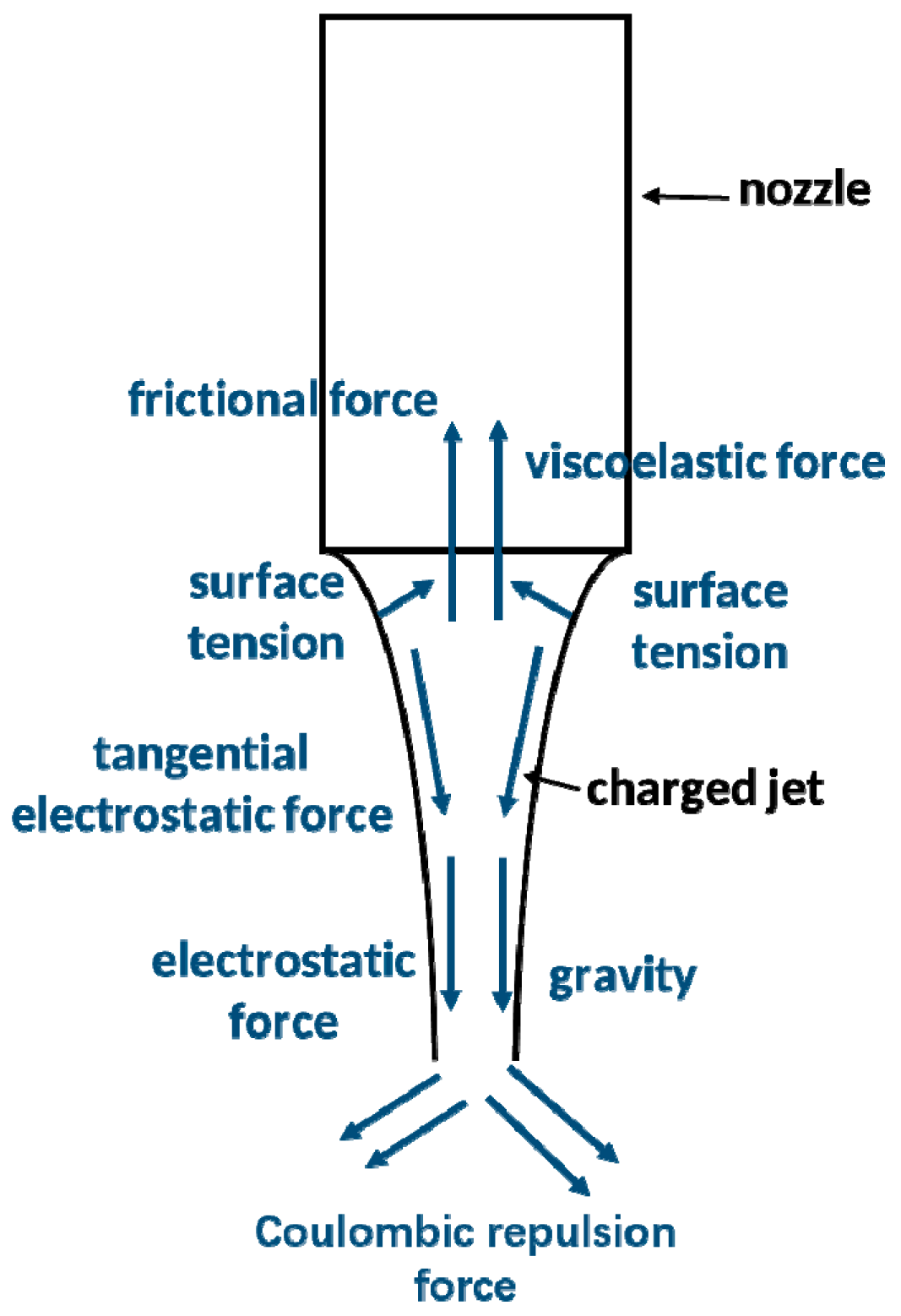
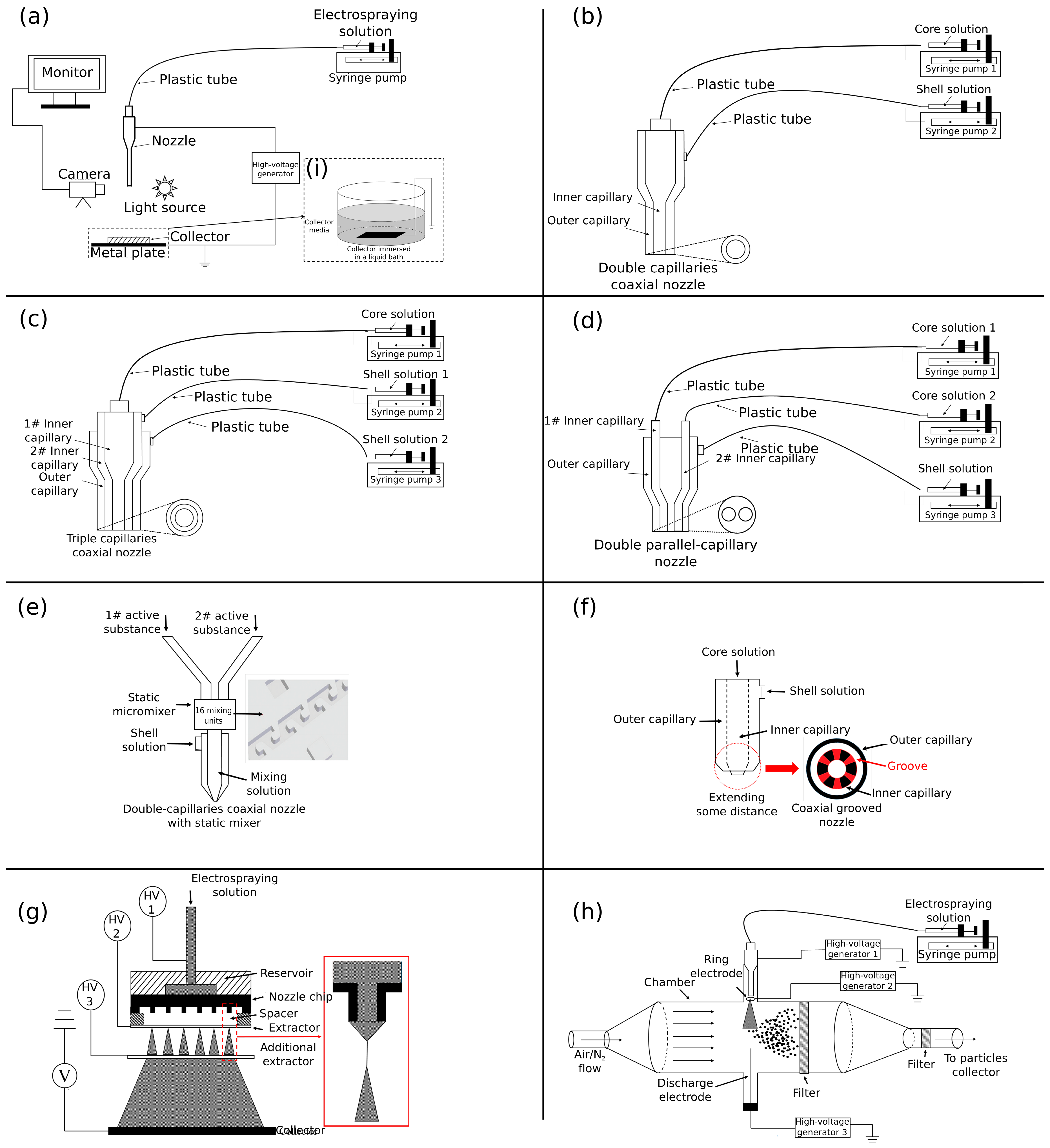
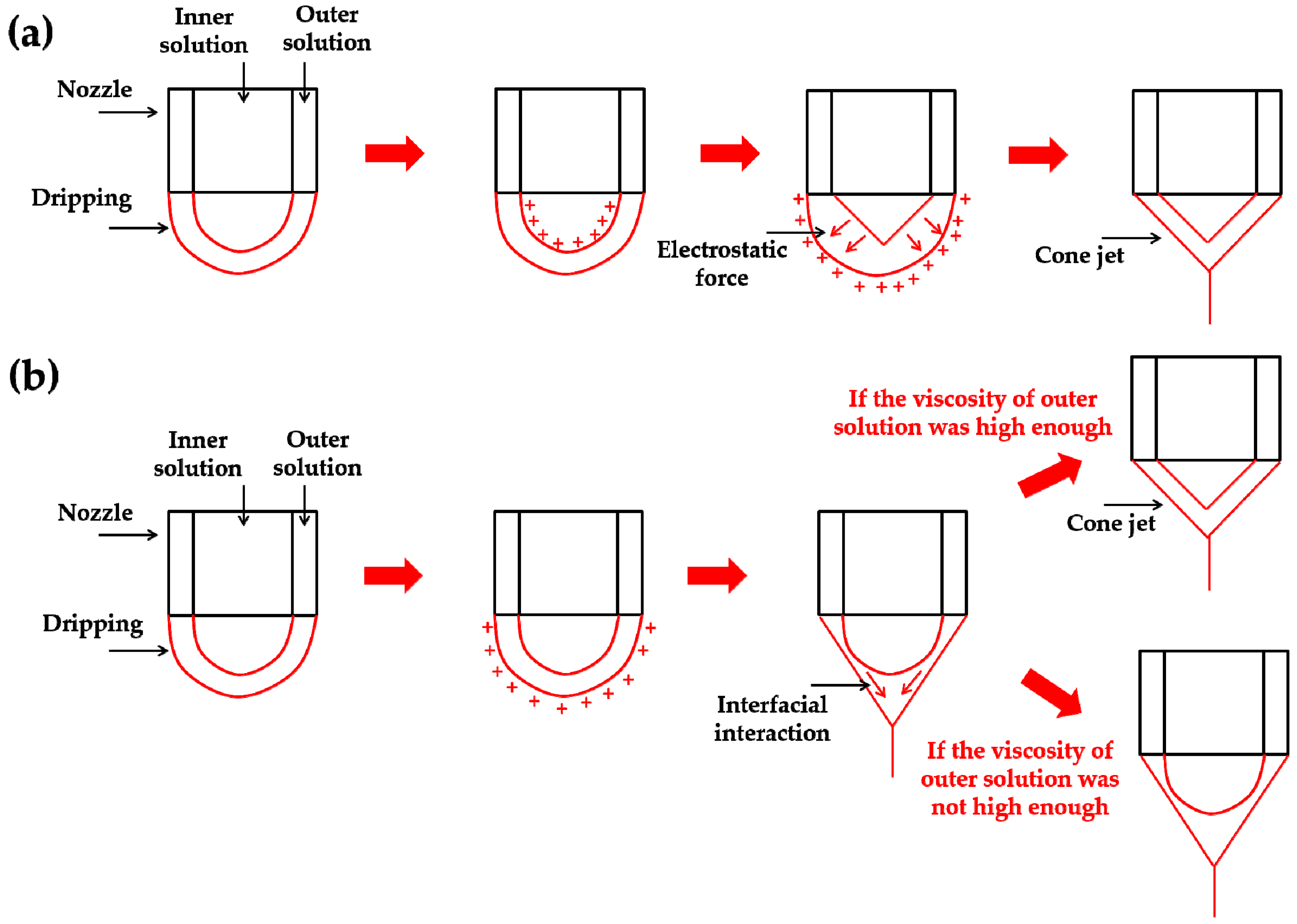
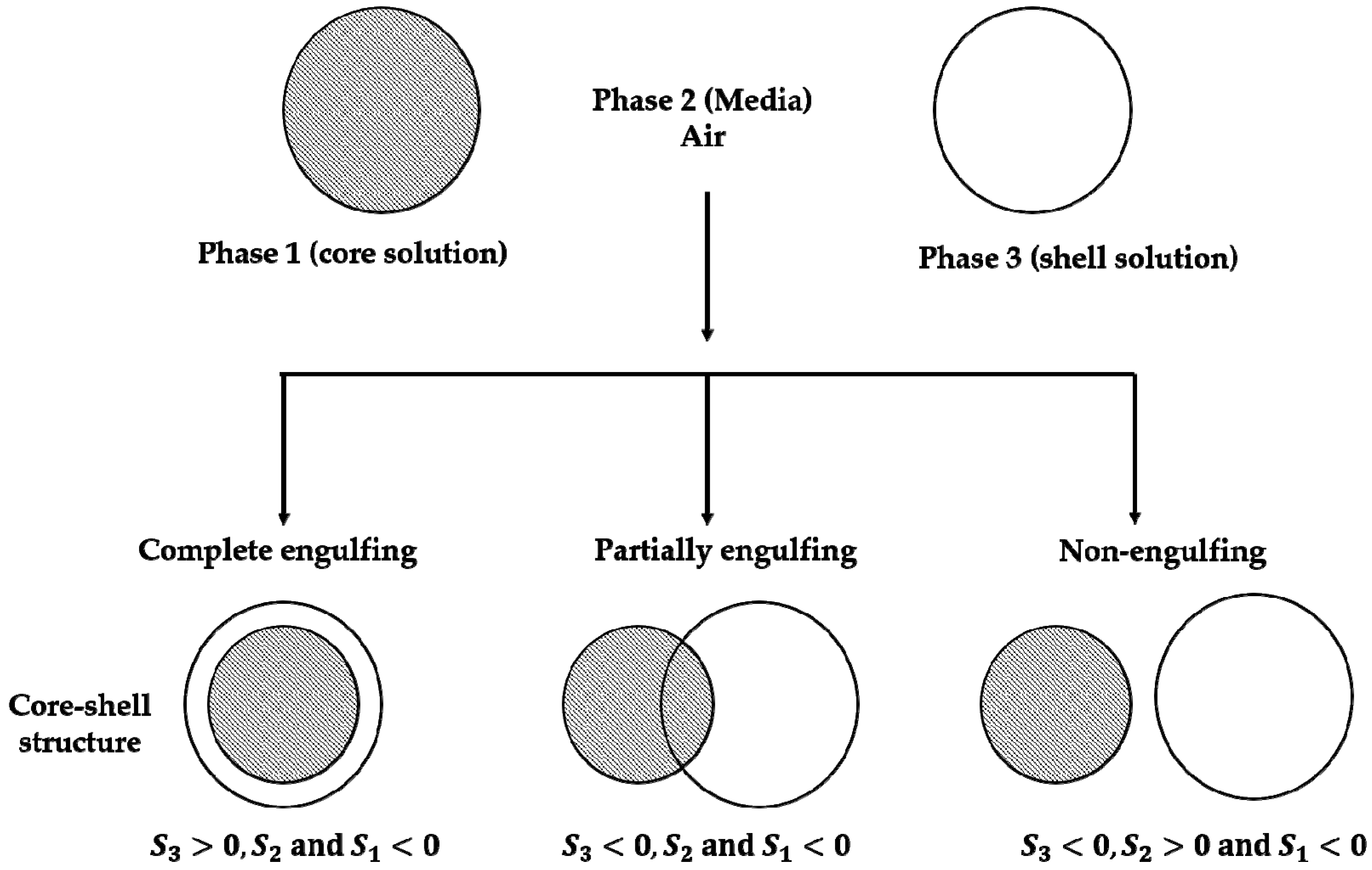
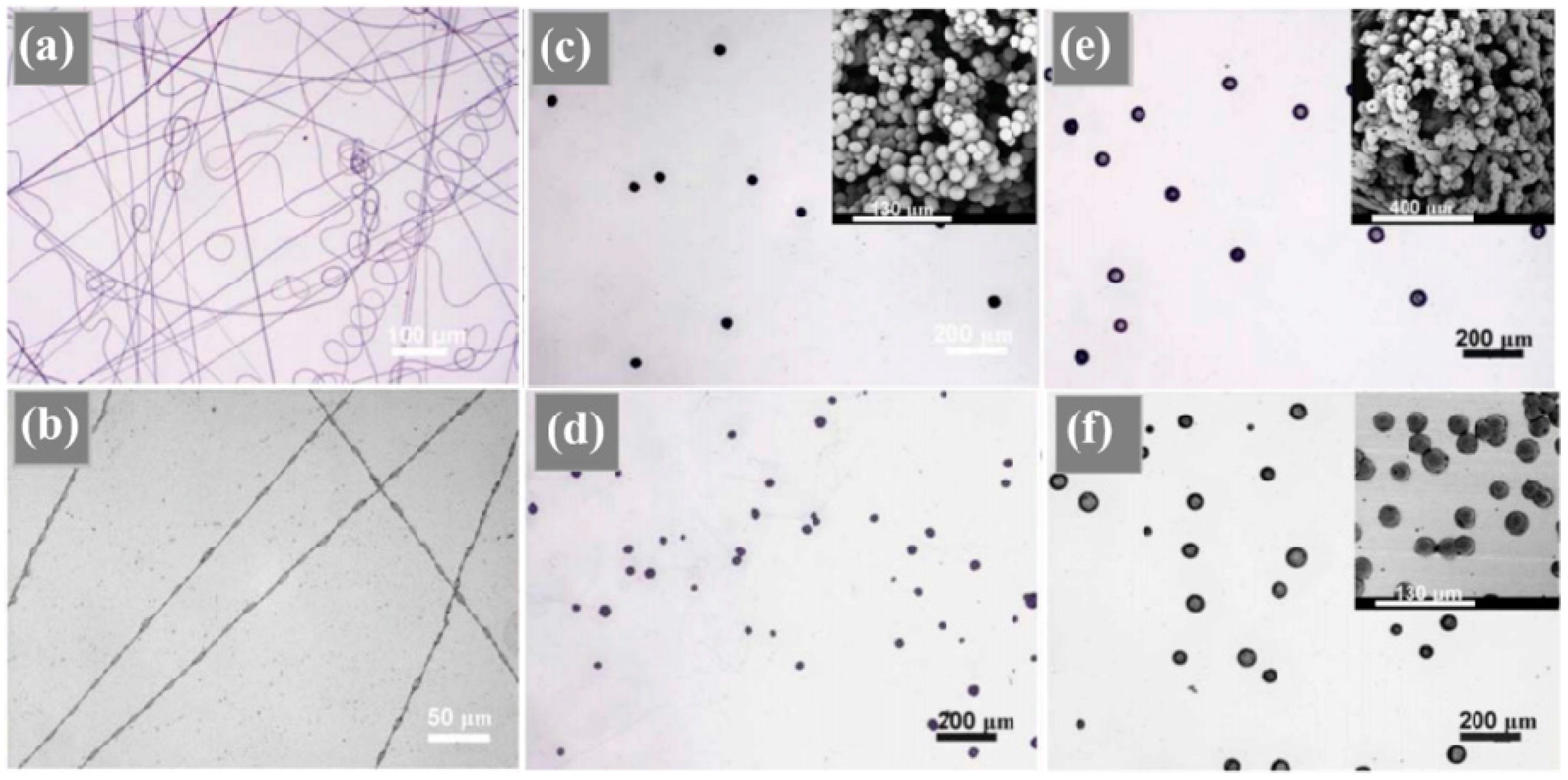
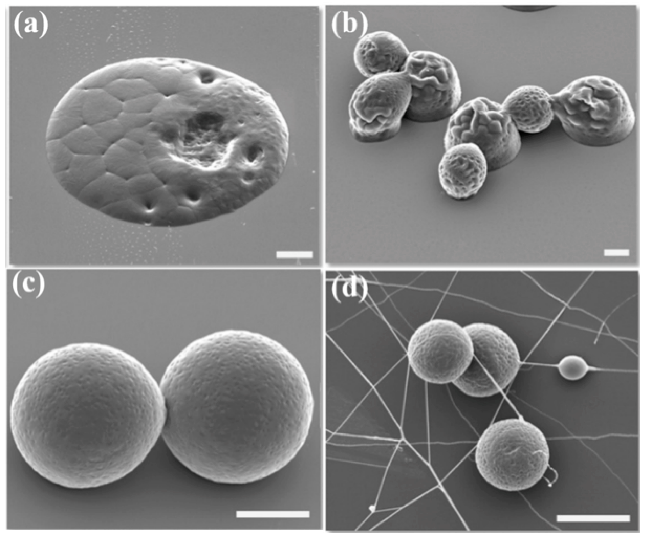
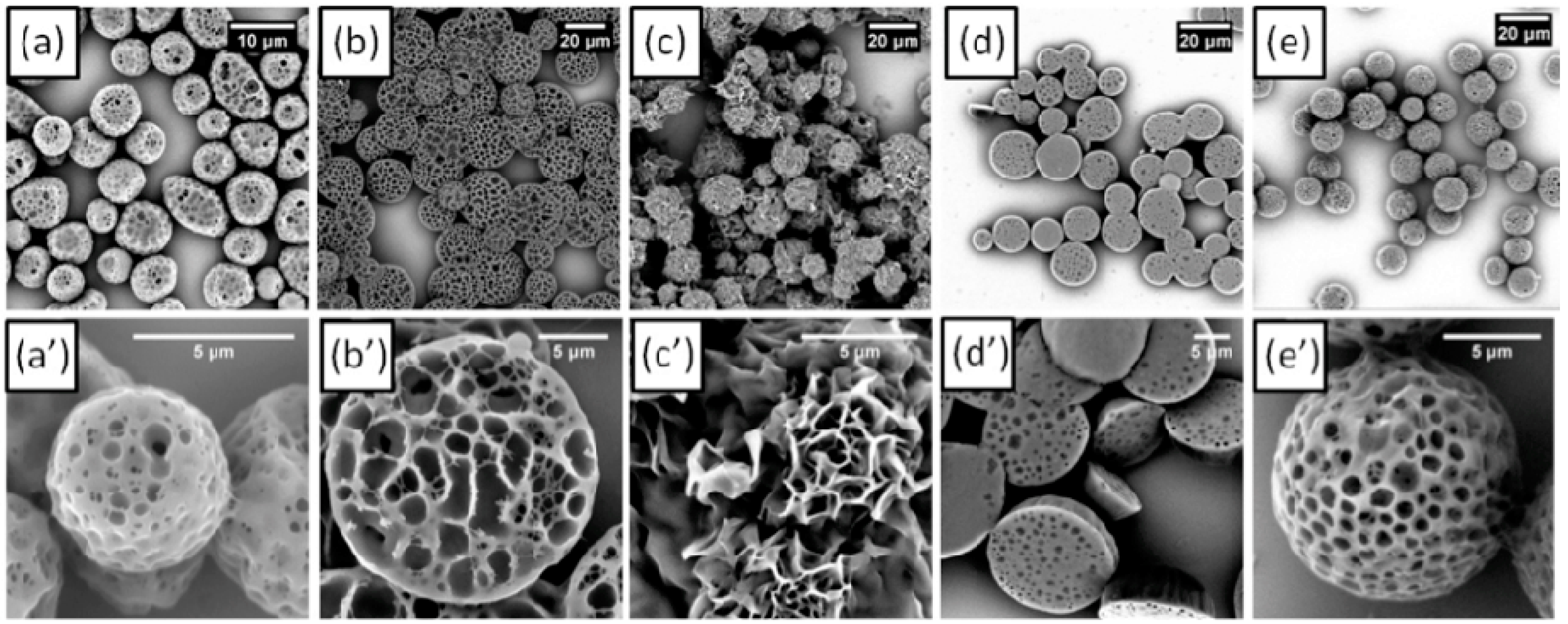
Table 1.
Hansen solubility parameters of PCL under different conditions and different measurement methods.
Table 1.
Hansen solubility parameters of PCL under different conditions and different measurement methods.
| Sample | Temperature °C | Method | Reference | ||||
|---|---|---|---|---|---|---|---|
| PCL | - | Group contribution | - | 17.0 | 4.8 | 8.3 | [99] |
| PCL-14,000-0.5 g/5 mL a | 25 | Swelling tests | 7.1 | 17.8 | 6.1 | 7.8 | [99] |
| PCL-14,000-0.5 g/5 mL | - | Turbidimetric titration (heptane/butanol) | 4.5 < R < 7.0 | 16.2 | 3.3 | 9.1 | [99] |
| PCL-14,000-0.5 g/5 mL | - | Turbidimetric titration (hexane/butanol) | 4.5 < R < 7.0 | 16.1 | - | 8.8 | [99] |
| PCL-14,000-2.5 g/5 mL | 25 | Swelling tests | 7.1 | 17.6 | 6.2 | 8.0 | [99] |
| PCL-65,000-0.5 g/5 mL | 25 | Swelling tests | 5.5 | 17.8 | 6.2 | 7.7 | [99] |
| PCL-65,000-0.5 g/5 mL | - | Turbidimetric titration (heptane/butanol) | 5.3 < R < 6.8 | 16.1 | 3.3 | 8.7 | [99] |
| PCL-65,000-0.5 g/5 mL | - | Turbidimetric titration (hexane/butanol) | 5.3 < R < 7.0 | 16.1 | 3.4 | 8.9 | [99] |
| PCL-65,000-2.5 g/5 mL | 25 | Swelling tests | 5.0 | 17.0 | 7.7 | 8.3 | [99] |
| PCL-7% by mass | 70 | Inverse gas chromatography | - | 15.5 | 2.4 | 7.4 | [100] |
| PCL-7% by mass | 80 | Inverse gas chromatography | - | 14.9 | 2.6 | 7.3 | [100] |
| PCL-7% by mass | 90 | Inverse gas chromatography | - | 14.5 | 2.3 | 7.4 | [100] |
| PCL-7% by mass | 100 | Inverse gas chromatography | - | 14.2 | 2.2 | 7.3 | [100] |
| PCL-7% by mass | 110 | Inverse gas chromatography | - | 13.8 | 2.2 | 7.3 | [100] |
a PCL-14000-0.5 g/5 mL represents that the molecular weight of PCL is 14,000 g/mol and the concentration of PCL is 0.5 g/5 mL.
Table 2.
Hansen solubility parameters of some common solvents and its solubility to PCL (part of the results obtained from swelling test and other part of results obtained from group distribution method).
Table 2.
Hansen solubility parameters of some common solvents and its solubility to PCL (part of the results obtained from swelling test and other part of results obtained from group distribution method).
| Sample | Distance to PCL a | Solubility b | Reference | |||
|---|---|---|---|---|---|---|
| Acetic acid | 14.5 | 8.0 | 13.5 | 8.7 | good | [99] |
| Acetone | 15.7 | 5.3 | 11.7 | 5.7 | partial | [99] |
| Acetonitrile | 15.3 | 18.0 | 6.1 | 12.9 | partial | [102,103] |
| Aniline | 19.4 | 5.1 | 10.2 | 4.3 | good | [103] |
| n-Butyl acetate | 15.8 | 3.7 | 6.3 | 4.8 | bad | [99] |
| Chloroform | 18.2 | 6.3 | 6.2 | 1.9 | good | [104] |
| Cyclohexanone | 17.7 | 9.8 | 5.1 | 4.5 | partial | [105] |
| Dichloromethane | 17.8 | 3.1 | 5.7 | 3.7 | good | [104] |
| Diethylene glycol | 16.2 | 14.7 | 20.5 | 15.6 | bad | [106] |
| Dimethylacetamide | 16.8 | 11.5 | 10.2 | 6.1 | partial | [107] |
| Dimethylformamide | 17.4 | 13.7 | 11.3 | 8.3 | partial | [108] |
| Dimethyl sulfoxide | 18.4 | 16.4 | 10.2 | 10.6 | bad | [99] |
| Ethyl acetate | 15.8 | 5.3 | 7.2 | 4.0 | partial | [99] |
| Dichloroethane | 19.0 | 7.4 | 4.1 | 4.7 | good | [109] |
| Ethanol | 15.8 | 8.8 | 19.4 | 12.5 | bad | [99] |
| Ethylene glycol | 17.0 | 11.05 | 26.0 | 18.9 | bad | [103] |
| Formic acid | 14.3 | 11.9 | 16.6 | 12.5 | partial | [99] |
| Glycerol | 20.5 | 14.6 | 19.1 | 15.2 | bad | [110] |
| Methanol | 15.1 | 12.3 | 22.3 | 16.6 | bad | [108] |
| Methyl acetate | 15.5 | 7.2 | 7.6 | 4.5 | NT | [99] |
| 1-Pentanol | 15.9 | 4.5 | 13.9 | 7.3 | bad | [104] |
| 1-Propanol | 16.0 | 6.8 | 17.4 | 10.2 | bad | [99] |
| Tetrahydrofuran | 16.8 | 5.7 | 8.0 | 1.9 | good | [108] |
| water | 15.6 | 16.0 | 42.3 | 36.1 | bad | [111] |
| N-Methyl-2-pyrolidone | 18.0 | 12.3 | 7.2 | 6.2 | partial | [103] |
| Pyridine | 18.9 | 10.6 | 5.9 | 5.4 | good | [108] |
| Benzyl alcohol | 18.5 | 6.3 | 13.9 | 10.7 | good | [112] |
| Carbon tetrachloride | 17.8 | 0.0 | 0.6 | 9.5 | partial | [108] |
| Toluene | 18.0 | 1.4 | 2.0 | 7.6 | good | [108] |
| Benzene | 18.4 | 0.0 | 2.0 | 8.6 | good | [108] |
| Ethyl formate | 15.5 | 8.4 | 8.4 | 5.0 | NT | [99] |
| Methyl ethyl ketone | 16.0 | 9.0 | 5.1 | 5.2 | partial | [99] |
| Isopropyl acetate | 14.9 | 1.4 | 4.1 | 8.3 | NT | [99] |
| 2-Butanol | 15.8 | 5.7 | 14.5 | 7.7 | bad | [99] |
| 1-Butanol | 16 | 5.7 | 15.8 | 8.7 | bad | [99] |
| Isopropyl benzene | 16.2 | 7.0 | 0.0 | 8.4 | NT | [99] |
| Isopropyl alcohol | 15.8 | 6.1 | 16.4 | 9.4 | bad | [113] |
| Isobutanol | 15.1 | 5.7 | 15.9 | 9.6 | NT | [99] |
| Heptane | 15.3 | 0.0 | 0.0 | 11.1 | bad | [99] |
| Pentane | 14.5 | 0.0 | 0.0 | 11.8 | bad | [99] |
| Styrene | 18.6 | 1.0 | 4.1 | 6.4 | NT | [108] |
| Anisole | 17.8 | 4.1 | 6.7 | 2.4 | good | [99] |
| 1,4-Dioxane | 19.0 | 1.8 | 7.4 | 5.1 | good | [111] |
| Methyl salicylate | 18.1 | 8.0 | 13.9 | 6.4 | good | [114] |
| Methyl formate | 15.3 | 8.4 | 10.2 | 5.8 | good | [115] |
| 2-Chloroethanol | 16.9 | 8.8 | 17.2 | 9.9 | good | [115] |
| o-Xylene | 17.8 | 1.0 | 3.1 | 7.3 | good | [108] |
| Benzaldehyde | 19.4 | 7.4 | 5.3 | 4.4 | good | [108] |
| 1,2-Dichlorobenzene | 19.2 | 6.3 | 3.3 | 5.4 | good | [112] |
| Acetyl chloride | 15.8 | 10.6 | 3.9 | 7.0 | good | [116] |
| Furan | 17.8 | 1.8 | 5.3 | 5.1 | good | [111] |
| Isopropanol | 15.8 | 6.1 | 16.4 | 9.4 | bad | [117] |
| Hexafluoroisopropanol | 14.17 | 2.41 | 13.89 | 10.0 | good | [118] |
| Trifluoroethanol | 15.9 | 9.7 | 17.8 | 11.2 | good | [119] |
a The distance from solvent to PCL is calculated taking in account the Hansen’s solubility parameters of PCL = 17.7, = 6.2 and = 7.8 (temperature: 25 °C). b As for the solubility to PCL, good means the solvent can dissolve PCL completely; partial means the solvent can only dissolve PCL at lower concentration or lower molecular weight; bad means the solvent cannot solubilize PCL at any concentration and molecular weight; NT represents “not tested” or uncertain.
Table 3.
Some solution properties for achieving cone jet during the PCL electrohydrodynamic process.
Table 3.
Some solution properties for achieving cone jet during the PCL electrohydrodynamic process.
| PCL Molecular Weight (g/mol) | Solvent | Concentration (wt.%) | Applied Voltage (kV) | Flow Rate (μL/min) | Working Distance (cm) | Electrical Conductivity (μS/m) | Surface Tension (mN/m) | Viscosity (mPa·s) | Size (μm) and Morphology | Reference |
|---|---|---|---|---|---|---|---|---|---|---|
| 45,000 | toluene | 5 | 11–18.5 | 20–50 | 5 | - | 26.5 | 3.0 | 20–140, spherical and smooth | [126] |
| 45,000 | toluene | 7 | 10.8–18.5 | 20–50 | 5 | - | 28.0 | 6.7 | 30–300, spherical and smooth | [126] |
| 45,000 | toluene | 10 | 12–18 | 20–50 | 5 | - | 28.5 | 11 | 40–500, spherical and smooth | [126] |
| 10,000 | toluene | 15 | 10–13 | 20–50 | 5 | - | 28.4 | 6.0 | 100–380, spherical and smooth | [126] |
| 10,000 | toluene | 20 | 7.7–12.8 | 20–50 | 5 | - | 29.6 | 16 | 200–600, spherical and smooth | [126] |
| 10,000 | toluene | 25 | 8.5–12.8 | 20–50 | 5 | - | 32.8 | 25 | 180–600, spherical and smooth | [126] |
| 14,000 | dimethylacetamide | 2 | 7–10.5 | 2.5–50 | 2 | 3.4 | 29 | 2.6 | 0.3–0.4, spherical and smooth | [127] |
| 14,000 | dimethylacetamide | 5 | 9.0–14.5 | 2.5–50 | 2 | 1.8 | 29 | 4.6 | 0.5–0.8, spherical and smooth | [127] |
| 14,000 | dimethylacetamide | 10 | 9.5–15.5 | 2.5–50 | 2 | 0.8 | 32 | 11.1 | 3.0–5.2, spherical and smooth | [127] |
| 43,000–50,000 | methanol/chloroform (3:7) | 1.5 | 12 | 16.67 | 12 | 0.02 | - | 2.4 | - | [128] |
| 45,000 | dichloromethane | 3 | 9–12 | 25 | 10 | 1.0 | 24.7 | 6.3 | 0.5–1.0, spherical and smooth | [129] |
| 45,000 | dichloromethane | 8 | 11–14 | 50 | 10 | 1.0 | 27.5 | 12.3 | ~10, fibrous and wrinkle | [129] |
| 45,000 | dichloromethane | 6 | 6.9–7.9 | 50 | 5–30 | 1.0 | 24.7 | 6.3 | 0.22–0.32, spherical and smooth | [130] |
| 43,000–50,000 | chloroform | 1.5 | 8 | 16.67 | 12 | - | - | - | - | [129] |
| 50,000 | chloroform | 9 | 10 | 8.33 | 25 | - | - | - | 17.80 ± 4.76, spherical and wrinkle | [92] |
| 45,000 | chloroform | 9 | 7.5 | 5 | 10 | - | - | - | 30–50, spherical and smooth | [98] |
Table 4.
Mean diameter of electrosprayed PCL microparticles obtained from different PCL concentration, molecular weight, and solvent systems.
Table 4.
Mean diameter of electrosprayed PCL microparticles obtained from different PCL concentration, molecular weight, and solvent systems.
| PCL Molecular Weight (g/mol) | PCL Concentration (wt.%) | Solvent Systems | Mean Diameter (μm) | Reference |
|---|---|---|---|---|
| 14,000 a | 0.5 | dichloromethane | 6.81 ± 1.94 | [147] |
| 14,000 a | 1.0 | dichloromethane | 7.81 ± 2.19 | [147] |
| 14,000 a | 3.0 | dichloromethane | 10.55 ± 1.44 | [147] |
| 14,000 a | 6.0 | dichloromethane | 16.84 ± 0.88 | [147] |
| 14,000 b | 3.0 | dichloromethane | 6.21 ± 1.44 | [147] |
| 14,000 b | 3.0 | acetonitrile | 2.25 ± 0.55 | [147] |
| 14,000 b | 3.0 | tetrahydrofuran | 7.49 ± 0.08 | [147] |
| 13,000 c | 5.0 | chloroform | 57.72 | [95] |
| 13,000 c | 7.4 | chloroform | 23.19 ± 4.18 | [95] |
| 13,000 c | 8.7 | chloroform | 20.50 | [95] |
| 13,000 c | 9.6 | chloroform | 9.73 | [95] |
| 45,000 d | 5.0 | toluene | 20 | [126] |
| 45,000 d | 7.0 | toluene | 50 | [126] |
| 45,000 d | 10.0 | toluene | 120 | [126] |
| 10,000 e | 15.0 | toluene | 220 | [126] |
| 10,000 e | 20.0 | toluene | 200 | [126] |
| 10,000 e | 25.0 | toluene | 320 | [126] |
a operating parameters: air flow rate: 20 L/min, working solution flow rate: 3 mL/h, nozzle size: 0.91 mm, voltage of nozzle and ring 8.8 and 7.1 kV; b operating parameters: air flow rate: 20 L/min, working solution flow rate: 3 mL/h, nozzle size: 0.34 mm, voltage of nozzle and ring 8.8 and 7.1 kV; c operating parameters: 26 G for needle gauge, 20–25 cm for tip-to-collector distance, 0.5 mL/h for flow rate and 10 kV for voltage; d operating parameters: working distance: 5 cm, applied voltage: 13–14.7 kV, working solution flow rate: 30 μL/min; e operating parameters: working distance: 5 cm, applied voltage: 9.5–9.8 kV, working solution flow rate: 30 μL/min.
Table 5.
Operating parameters value ranges to achieve cone-jet mode in the electrospraying process of PCL.
Table 5.
Operating parameters value ranges to achieve cone-jet mode in the electrospraying process of PCL.
| PCL Molecular Weight (g/mol) | Solvent | Concentration (wt.%) | Applied Voltage (kV) | Flow Rate (μL/min) | Working Distance (cm) | Electrical Conductivity (μS/m) | Surface Tension (mN/m) | Viscosity (mPa·s) | Reference |
|---|---|---|---|---|---|---|---|---|---|
| 45,000 | toluene | 5 | 11–18.5 | 20–50 | 5 | - | 26.5 | 3.0 | [126] |
| 45,000 | toluene | 7 | 10.8–18.5 | 20–50 | 5 | - | 28.0 | 6.7 | [126] |
| 45,000 | toluene | 10 | 12–18 | 20–50 | 5 | - | 28.5 | 11 | [126] |
| 10,000 | toluene | 15 | 10–13 | 20–50 | 5 | - | 28.4 | 6.0 | [126] |
| 10,000 | toluene | 20 | 7.7–12.8 | 20–50 | 5 | - | 29.6 | 16 | [126] |
| 10,000 | toluene | 25 | 8.5–12.8 | 20–50 | 5 | - | 32.8 | 25 | [126] |
| 14,000 | dimethylacetamide | 2 | 7–10.5 | 2.5–50 | 2 | 3.4 | 29 | 2.6 | [127] |
| 14,000 | dimethylacetamide | 5 | 9.0–14.5 | 2.5–50 | 2 | 1.8 | 29 | 4.6 | [127] |
| 14,000 | dimethylacetamide | 10 | 9.5–15.5 | 2.5–50 | 2 | 0.8 | 32 | 11.1 | [127] |
| 43,000–50,000 | methanol/chloroform (3:7) | 1.5 | 12 | 16.67 | 12 | 0.02 | - | 2.4 | [128] |
| 45,000 | dichloromethane | 3 | 9–12 | 25 | 10 | 1.0 | 24.7 | 6.3 | [129] |
| 45,000 | dichloromethane | 8 | 11–14 | 50 | 10 | 1.0 | 27.5 | 12.3 | [129] |
| 45,000 | dichloromethane | 6 | 6.9–7.9 | 50 | 5–30 | 1.0 | 24.7 | 6.3 | [130] |
| 43,000–50,000 | chloroform | 1.5 | 8 | 16.67 | 12 | - | - | - | [129] |
| 50,000 | chloroform | 9 | 10 | 8.33 | 25 | - | - | - | [92] |
| 45,000 | chloroform | 9 | 7.5 | 5 | 10 | - | - | - | [98] |
Table 6.
Applications of electrosprayed PCL microparticles with different sizes and morphologies.
| PCL Molecular Weight (g/mol) | Mean Diameter (μm) | Morphology | Potential Applications | Reference |
|---|---|---|---|---|
| 65,000 | 7–11 | Spherical, smooth and compact | Control release of anticancer drug | [94] |
| 14,000 | 0.3–5 | Smooth and compact | Drug control release | [127] |
| 80,000 | 0.2–4.5 | Smooth and compact | Drug delivery system | [163] |
| 80,000 | 0.63–0.65 | Spherical, smooth and compact | Control release and drug delivery | [164] |
| 45,000 | 5–20 | Porous and wrinkle | Control release and drug delivery | [152] |
| 80,000 | 0.72–3.5 | Spherical shape, porous and fibreless | Tissue engineering | [165] |
| 80,000 and 45,000 | 125–450 | Porous, loose and spherical | Tissue engineering and cell therapy | [162] |
| 4500 | 10–15 | Yolk-shell, smooth and spherical | Biomedical engineering | [166] |
| 80,000 | 0.4–2 | Fibrous and smooth | Tissue engineering | [167] |
| 41,000 | 14–18 | Fibrous, wrinkle and porous | Tissue engineering | [168] |
| 80,000 | 0.7–2.5 | Nanofiber, wrinkle and compact | Food packaging (Vitamin) | [169] |
| 10,000 | 0.5–4.5 | Fibrous and smooth | Refrigeration and food packaging | [170] |
| 10,000 | 0.1–2.5 | Fibrous and smooth | Refrigeration and food packaging | [171] |
© 2019 by the authors. Licensee MDPI, Basel, Switzerland. This article is an open access article distributed under the terms and conditions of the Creative Commons Attribution (CC BY) license (http://creativecommons.org/licenses/by/4.0/).
Share and Cite
MDPI and ACS Style
Zhang, S.; Campagne, C.; Salaün, F. Influence of Solvent Selection in the Electrospraying Process of Polycaprolactone. Appl. Sci. 2019, 9, 402. https://doi.org/10.3390/app9030402
AMA Style
Zhang S, Campagne C, Salaün F. Influence of Solvent Selection in the Electrospraying Process of Polycaprolactone. Applied Sciences. 2019; 9(3):402. https://doi.org/10.3390/app9030402
Chicago/Turabian StyleZhang, Shengchang, Christine Campagne, and Fabien Salaün. 2019. "Influence of Solvent Selection in the Electrospraying Process of Polycaprolactone" Applied Sciences 9, no. 3: 402. https://doi.org/10.3390/app9030402
Note that from the first issue of 2016, this journal uses article numbers instead of page numbers. See further details here.