A New Technique for Batch Production of Tubular Anodic Aluminum Oxide Films for Filtering Applications


1
Department of Mechanical Engineering, National United University, Miaoli 36003, Taiwan
2
Hydrotech Research Institute, National Taiwan University, Taipei 10617, Taiwan
3
Department of Chemistry and Physics, Fayetteville State University, Fayetteville, NC 28301, USA
4
Department of Energy Engineering, National United University, Miaoli 36003, Taiwan
5
Department of Mechanical Engineering, National Taiwan University of Science and Technology, Taipei 10607, Taiwan
6
Department of Materials Science and Engineering, Northwestern University, Evanston, IL 60208, USA
*
Authors to whom correspondence should be addressed.
Appl. Sci. 2018, 8(7), 1055; https://doi.org/10.3390/app8071055
Submission received: 1 May 2018
/
Revised: 31 May 2018
/
Accepted: 26 June 2018
/
Published: 28 June 2018
(This article belongs to the Special Issue Mechanical Behaviour of Aluminium Alloys)
Abstract
:With larger surface areas and nanochannels for mass delivery and gas diffusion, three-dimensional tubular anodic aluminum oxide (AAO) films have practical advantages over two-dimensional AAO films for medical and energy applications. In this research, we have developed a process for batch production of tubular AAO films using a 6061 Al tube. The tubular AAO films have open nano-channels on both sides, with average pore dimensions of about 60 nm and pore densities of about 108 to 109 pore/cm2. It was found that the porous AAO material with nano-channel structure exhibited dialysis behavior, allowing for liquid/gas exudation through diffusion between the inner and outer surfaces of the tubular AAO films. Ar gas bearing test and aeration test were conducted to find the pressure bearing capacity of tubular AAO films. It was demonstrated that the AAO film with a thickness of 100 μm can resist an argon pressure up to 8 atm; however, 30 μm AAO film can only withstand 3 atm of Ar gas. The tubular AAO films with exudation characteristics have the potential for applications in advanced technologies, such as liquid or gas filters, drug delivery, and energy applications.
1. Introduction
High-quality AAO (anodic aluminum oxide) films provide ordered straight channels, with a diameter of 10–500 nm, pore density of 107–1011 pore/cm2, and thickness of 1–300 μm [1,2]. With large surface areas, high mechanical strength, and flexibility, AAO can be used in medical or energy applications, such as drug delivery and detection [3,4]. The large AAO surfaces can be utilized to absorb the bio-indicators or drugs, and the releasing behavior can also be controlled based on the heat sensitivity. AAO has also found applications in energy conversion between carbon dioxide (CO2) and methanol (CH4) [5,6]. By loading photocatalyst particles on the AAO surface, such photocatalytic systems can be used to recycle carbon dioxide into organic compounds. Based on the features of larger surface areas and nanochannels for mass delivery and gas diffusion, three-dimensional (3D) structure of AAO films have practical advantages over two-dimensional (2D) AAO films for medical and energy applications.
AAO has a lower melting point than pure alumina because of the inclusions in the porous AAO structure. Spooner [7] presented the following compositions of alumina film anodized using sulfuric acid as electrolyte: Al2O3 (78.9 wt. %), Al2O3 · H2O (0.5 wt. %), Al2 (SO4)3, and H2O (0.4 wt. %). According to Akahori’s work [8], the melting point of AAO is near 1200 °C, and AAO template retains stable, at around 1000 °C [9], which is lower than that of bulk alumina (2017 °C for Al2O3(γ)). The AAO structure maintaining temperature of 1000 °C is stable enough to be a template for CaO-CaCO3 reaction at 894 °C.
In the past, tubular AAO has attracted attention. Several methods were proposed for the fabrication and applications of tubular AAO films. According to Altuntas’s report [10], the large area (50 cm2) free-standing AAO membranes was obtained by sputtering carbon onto AAO surface for conductive AAO biosensor applications, especially tubular AAO for filtering. Belwalkar [11] showed that AAO tubular membranes were fabricated from aluminum alloy tubes in sulfuric and oxalic acid electrolytes, the pore sizes were ranging from 14 to 24 nm, and the wall thicknesses was as high as 76 μm, which increased the mechanical strengths for handing. The pore density can be calculated by determining the number of pores according to the area fraction: P = Ap/[(π/4)D2], where P is the number of pores, Ap is the area fraction of pores, and D is the average pore diameter. Gong [12] presented that AAO membrance was prepared in 0.2 M oxalic acid electrolyte under 25 to 40 V applied for 11 to 18 h; additionally, the control in drug delivery by using nanoporous alumina tube capsules with pores of 25 to 55 nm was demonstrated. Kasi1 [13] further reported that the purity of Al is also a matter of great concern for AAO fabrication. Some applications, such as nano-templates for semiconductor industry, require a regular pore arrangement with a honeycomb structure, which cannot be achieved from low grade Al. Moreover, AAO membrane in tubular form can further satisfy the demand in both diffusive and convective filtration of hemodialysis.
The control in preparing tubular AAO is more challenging than flat AAO film on Al sheet because of film cracking issues. Since the AAO processes are sensitive to the operation conditions, defects may appear in AAO membranes if unsuitable conditions are applied. How to manage the variable conditions is pivotal, including electrolyte temperatures, applied voltages, electrolyte compositions, cooling stirring, and current density distribution. Kasi [14] reported that more cracks were generated in smaller diameter (2 mm) tube than larger one (19 mm). The number of cracks generated on the surface of tubular membrane is directly proportional to the thickness of AAO membrane. The result also showed that a crack free thicker membrane could only be obtained if the tube diameter is large. Itoh [15] also shows the AAO tubes that were synthesized by anodization from interior outwards were three times stronger than those anodized from the exterior surface. Grimes [16] demonstrated the nanoporous filter is useful for bio-filtration and gas separation, such as for controlling molecular transport in immunoisolation applications. Furthermore, AAO can also be formed to different geometric shapes. Yue [17] reported tubular anodic aluminum oxide (AAO) membranes with various geometries, including circle, square, and triangle, were fabricated using the “external anodizing” method. Adjust the membrane thickness through the second-step anodization time (10 to 28 h) was demonstrated to be feasible for avoiding the longitudinal cracks in various tubular AAO membranes.
In our previous research, we produced different nanostructures using high-quality AAO films [18,19,20,21]. However, the mass production of tubular AAO remains challenging. In this paper, based on our previous experience in AAO producing, a new technique is proposed for the batch production of tubular AAO films, and such batch production is an important factor in materials engineering [22].
2. Experimental Procedures
Tubular AAO films with an average pore size of about 60 nm and the film thickness of 40 μm were fabricated from 6061 aluminum alloy (Mg: 0.8~1.2%, Si: 0.4~0.8%, Cu: 0.15~0.40%, Al: base) tubes with a diameter of 20 mm by anodization processes. The experimental chemicals that were used in this experiment were of reagent grade without further purification, including perchloric acid (HClO4), ethylene glycol butyl ether (CH3(CH2)3OCH2CH2OH), ethanol (C2H6O), oxalic acid (C2H2O4), chromium trioxide (CrO3), phosphoric acid (H3PO4), cupric chloride (CuCl2), and hydrogen chloride (HCl). The experimental steps are as below: (a) stress relief (6061 Al, 300 °C, 1 h); (b) mechanical grinding on the outer surface of the Al tube (#2000 SiC paper); (c) electrolytic polishing (15 vol. % HClO4 + 15 vol. % (CH3(CH2)3OCH2CH2OH + 70 vol. % C2H6O, 15 °C, 42 V, 10 min); (d) 1st anodization (3 wt. % C2H2O4, 10 °C, 40 V, 1 h); (e) removal of 1st anodization film (1.8 wt. % CrO3 + 6 vol. % H3PO4 + 92 vol. % H2O, 70 °C, 50 min); (f) 2nd anodization (3 wt. % C2H2O4, 10 °C, 40 V, 5 h); (g) removal of Al substrate (12 wt. % CuCl2 + 8 vol. % HCl + 80 vol. % H2O, 25 °C, 14 min); (h) removal of barrier layer (5 vol. % H3PO4, 25 °C, 1 h); and, (i) pore widening (5 vol. % H3PO4, 25 °C, 45 min).
The AAO thickness between 30 to 100 μm were controlled by the anodization time from 3 to 24 h. The transmembrane pressure test on the tubular AAO films was carried out by purging Ar gas, and the exudation characteristic of the tubular AAO was tested with a red ink solution.
All of the experimental sample images were acquired using a digital camera (Nikon, COOLPIX A900, Japan). The microstructures of the fabricated samples were observed by a scanning electron microscope (SEM, JEOL 6500).
3. Results and Discussion
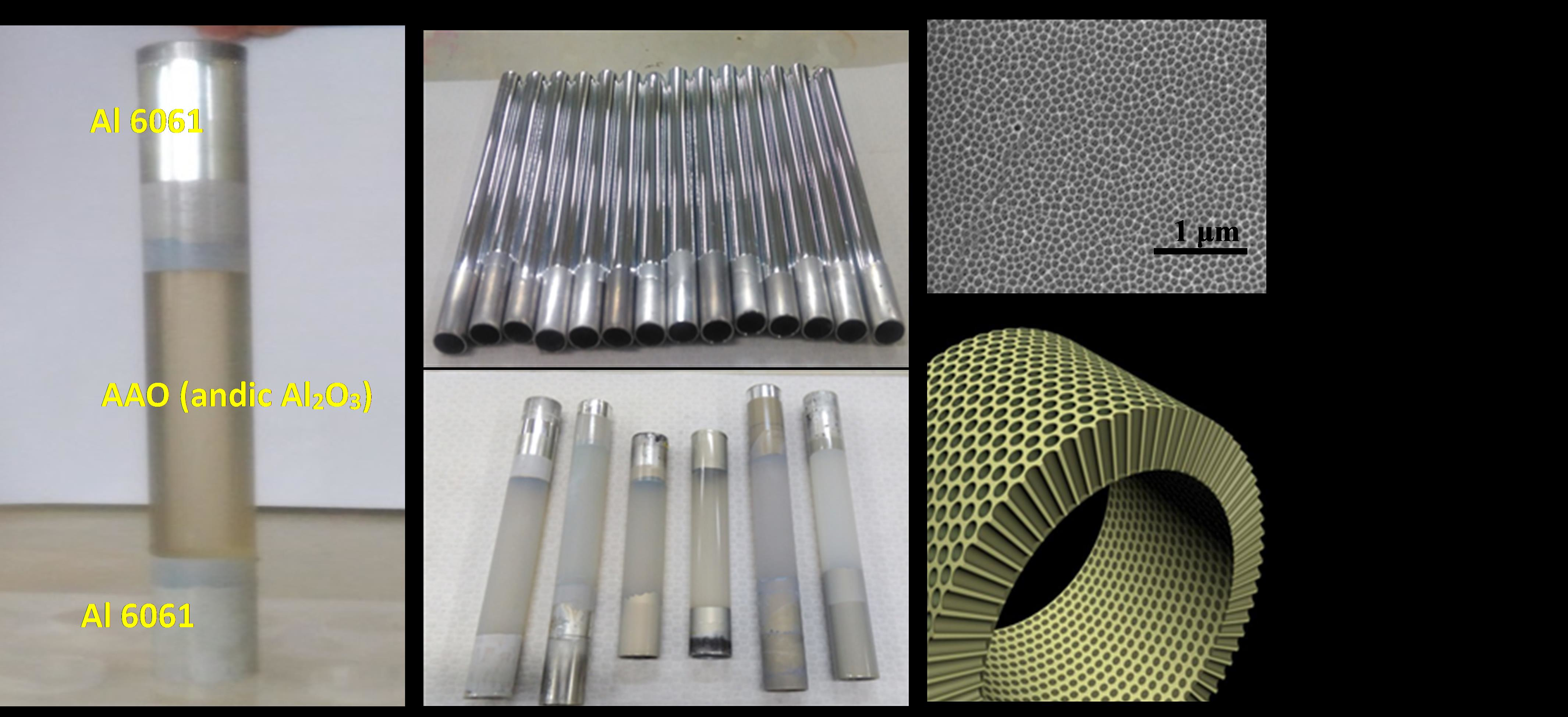
In order to quickly fabricate and reduce the cost of the tubular AAO process, a batch of aluminum tubes was set in the anodization mold. Silicone plugs were used to seal the bottoms of the tubes so that AAO formed on the outer surfaces of the aluminum tubes rather than on the inner surfaces. Based on our previous anodization process that is illustrated in Figure 1 [1], the solutions of each tank individually were (a) electro-polishing electrolyte (HClO4 solution); (b) water; (c) anodization electrolyte (oxalic acid solution); (d) AAO removal solution (H3PO4 solution); (e) aluminum removal solution (CuCl2 + HCl solution); and, (f) AAO pore widening solution (H3PO4 solution). The experimental parameters of solution temperature and applied voltage were controlled using a cooling/heating machine and programmable power supply, respectively. The aluminum tube, functioning as the working electrode, was in contact with a conducting copper sheet as the anode, and an aluminum sheet was in contact with the cathode as the counter.
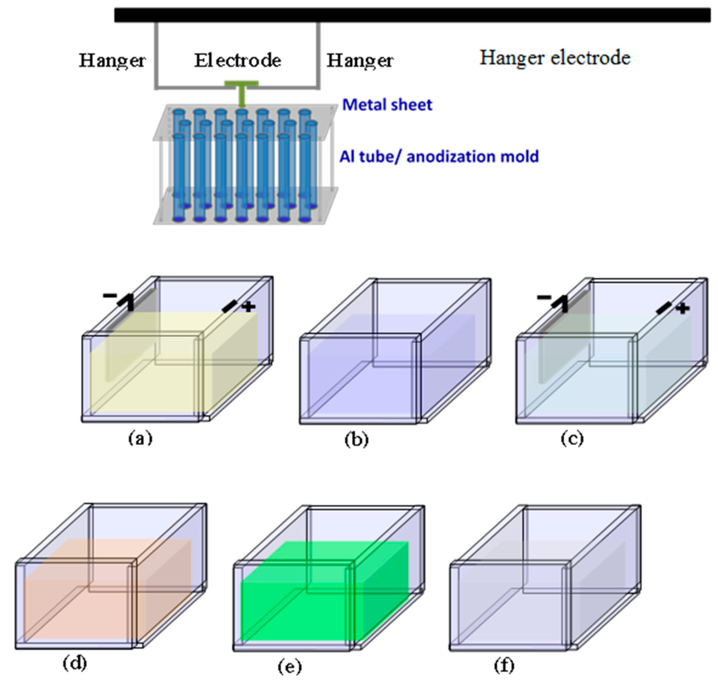
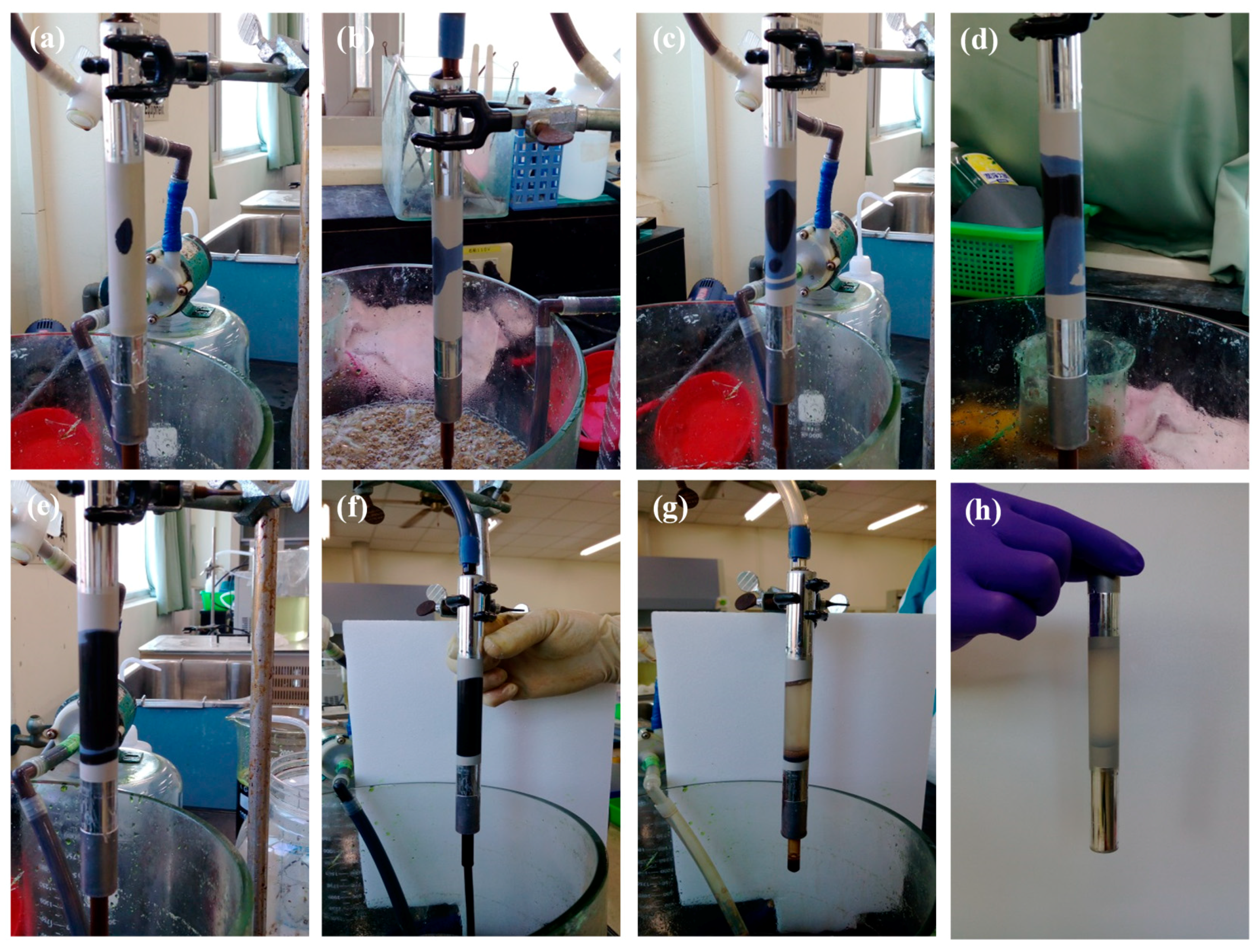
Figure 2 shows the set up to remove Al substrate, including Al removal solution (CuCl2 + HCl solution), pump, and pipes. After the removal solution was pumped into Al tube to etch Al for ten of minutes, translucent tubular AAO was obtained. The chemical displacement reaction between Al and Cu can be expressed as: 2 Al(s) + 3 CuCl2(s) → 3 Cu(s) + 2 AlCl3(s). By the way, HCl promotes the AlCl3 formation, and the reaction is denoted as: 2 Al(s) + 6 H+(aq) + 6 Cl−(aq) → 2 AlCl3(s) + 3 H2(g). Because this is an exothermic reaction during Al-Cu displacement reaction the cooling for etching bath is critical. Figure 3 shows the detailed Al removing processing flow. Most of Al substrate can be removed after a 15 min removing process.
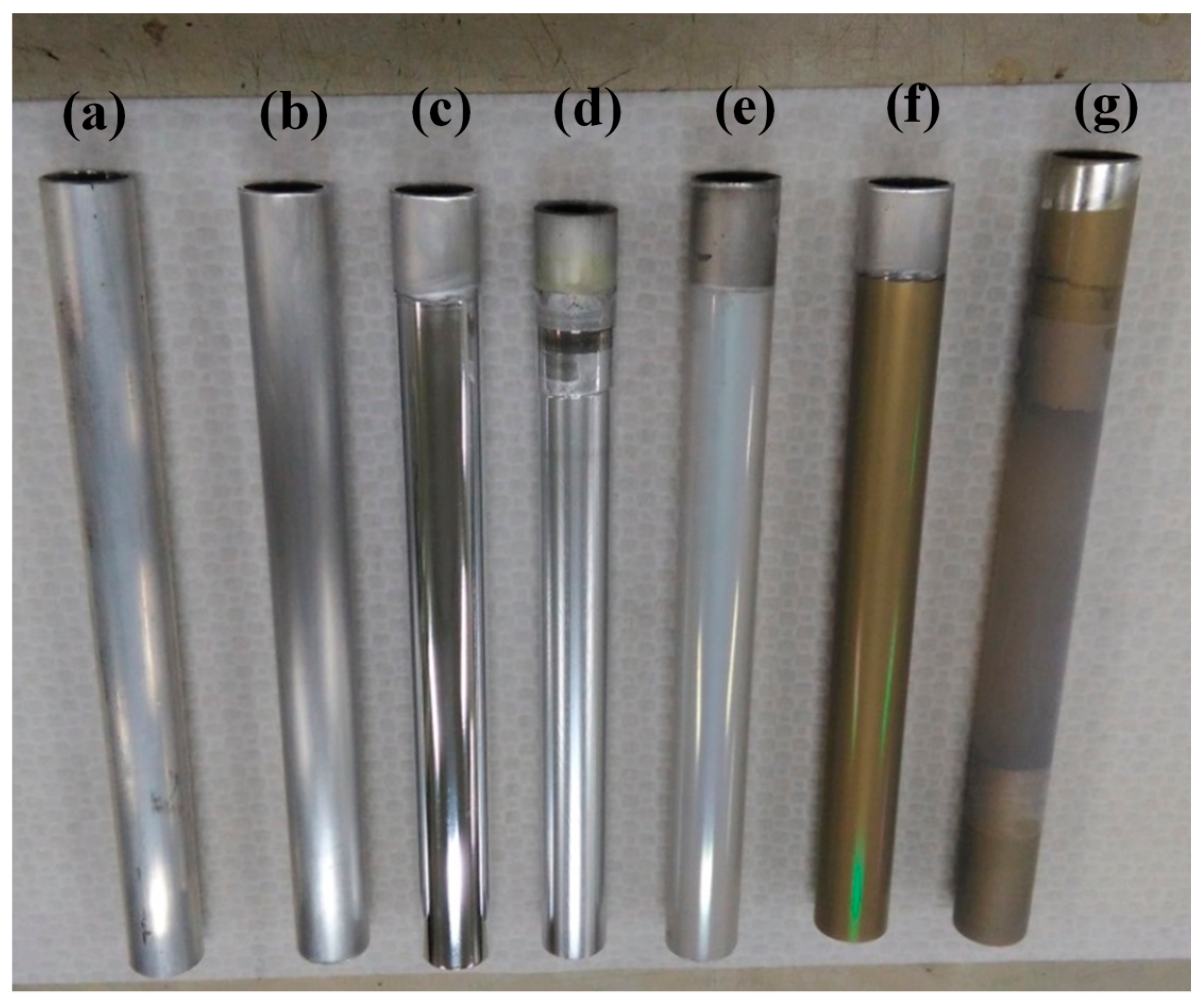
Figure 4 shows the optical images of the initial 6061 tube and anodic tubular aluminum oxide made by the assistance of electrochemical and wet-etching process. It includes the following steps: (a) the aluminum tube that contains many scratches; (b) most of rough scratches on aluminum tube were removed after mechanical grinded; (c) a mirror-like aluminum surface was achieved after electrolytic polished; (d) a uniformity AAO film was formed on the Al surface through the first anodization process; (e) ordering patterns were formed on the Al tube after removing the first anodization film; (f) AAO film was formed on the ordering pattern Al surface through the second anodization; and, (g) a translucent AAO film was presented after removing Al substrate.
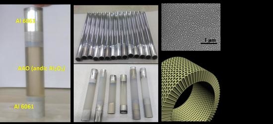
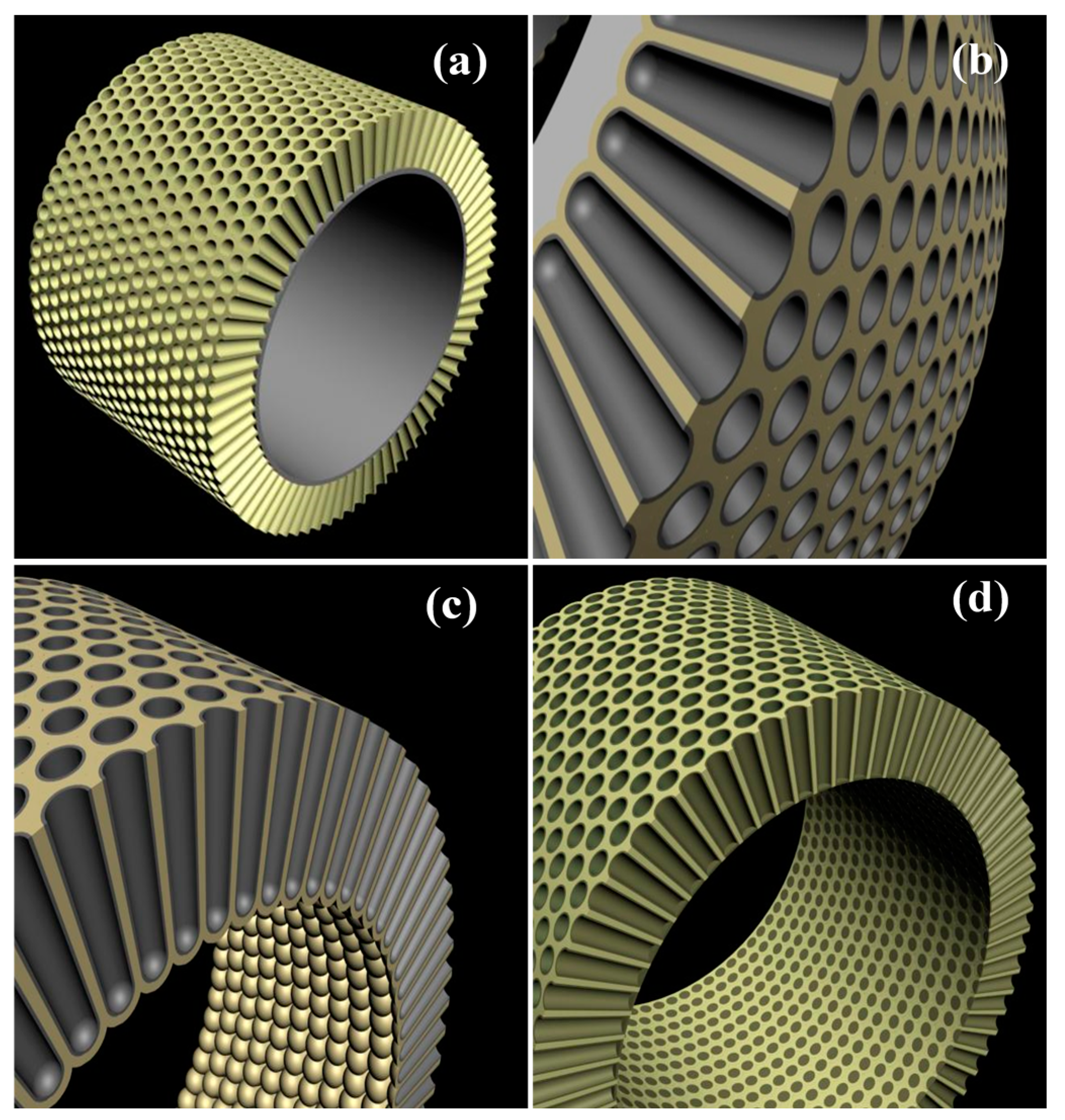
Figure 5 shows a schematic diagram of the tubular AAO micro-morphology. In the beginning, AAO film forms hexagonal channels because of the internal stress balance. Subsequently, the hexagonal channels are changed to a circular tube by anodization electrolyte etching. While the high purity Al tube is anodized, circular holes form on the hexagonal patterns of the anodic film. In Figure 5a, anodic aluminum oxide with regular pores on the Al tube surface was shown. Figure 5b is a lateral-view image of the anodic film, showing a straight channel with hemispherical closed barrier layer formation on the channel bottom. In Figure 5c, the aluminum substrate has been removed from the independent AAO film, and the anodic film presents a hemispherical closed barrier layer on the bottom. Because the closed barrier layer may affect the gas or liquid circulation in advanced applications, the barrier layer can be removed. In Figure 5d, the barrier layer is removed in a both-side open anodic channels. The anodic film structure is supported by a continuous wall, and both ends of the anodic tube are open to allow for air or liquid flow in the anodic tubes. However, in our experiment, 6061Al tubes were utilized as the raw material for anodization. AAO obtained from 6061Al has a worse microstructure than AAO prepared from pure Al.
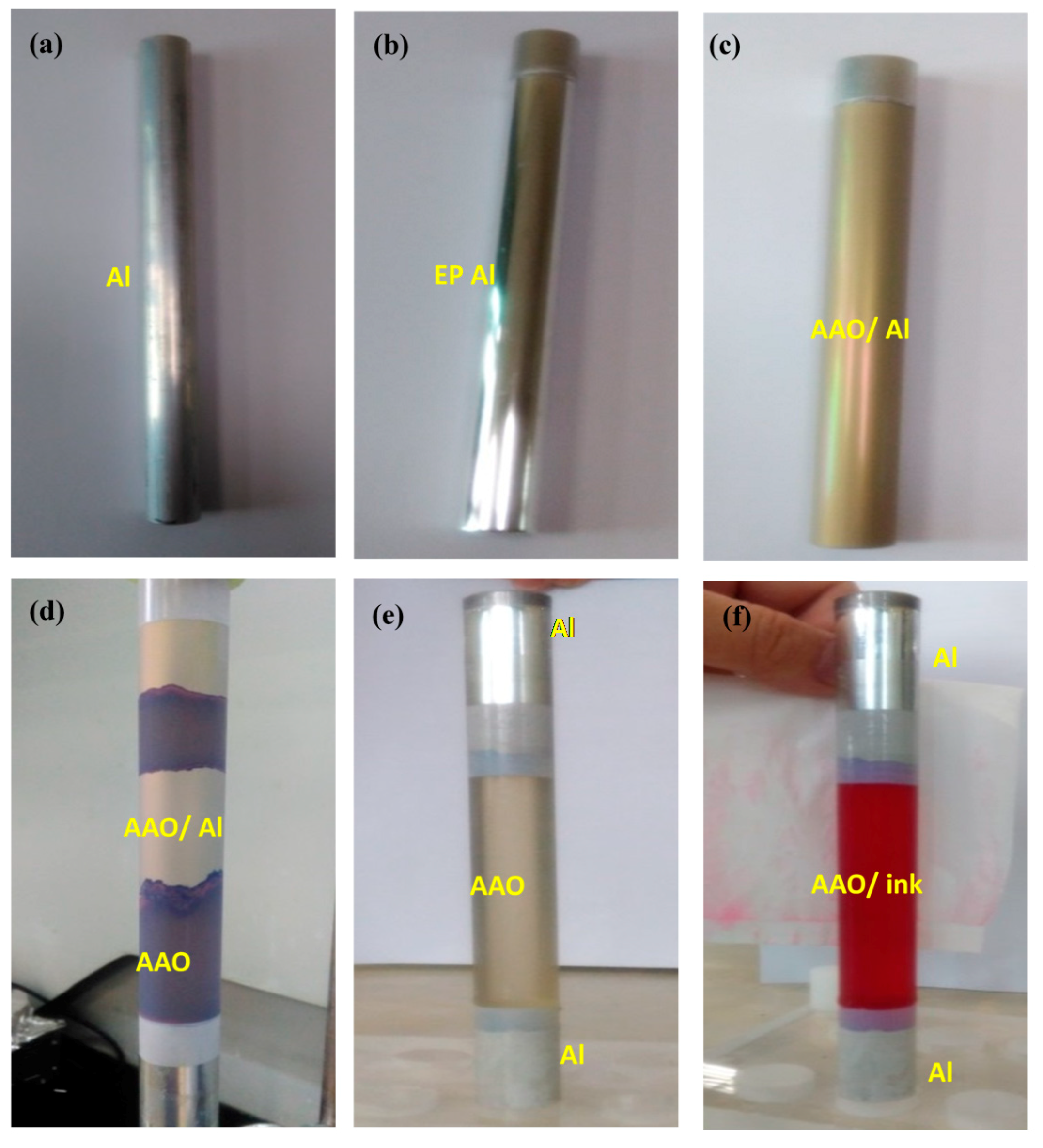
Figure 6 shows photos of the tubular AAO film formed with 6061Al tubes. Figure 6a shows the raw material, the 6061 Al tube, which has a rough surface before mechanical and electrical polishing. Figure 6b shows that the 6061 Al tube presents a flat surface that is suitable for the formation of high-quality AAO after electro-polishing (EP) process. In Figure 6c, the AAO film on the EP Al further presents golden color by oxidized in oxalic acid solution with a DC voltage of at 40 V. Figure 6d shows tubular AAO film partially with the inner EP Al surface; therefore, the Al substrate could be entirely removed by dipping in CuCl2 aqueous solution. The image shows that part of the Al substrate was removed, and the partially exposed AAO film is visible. In Figure 6e, the exposed AAO film with the Al rings on both sides further obtained after the Al substrate was totally removed. In future applications of tubular AAO, the Al rings on both sides can function as connectors. Figure 6f demonstrates that the red ink solution exuded through the AAO nano-pores.
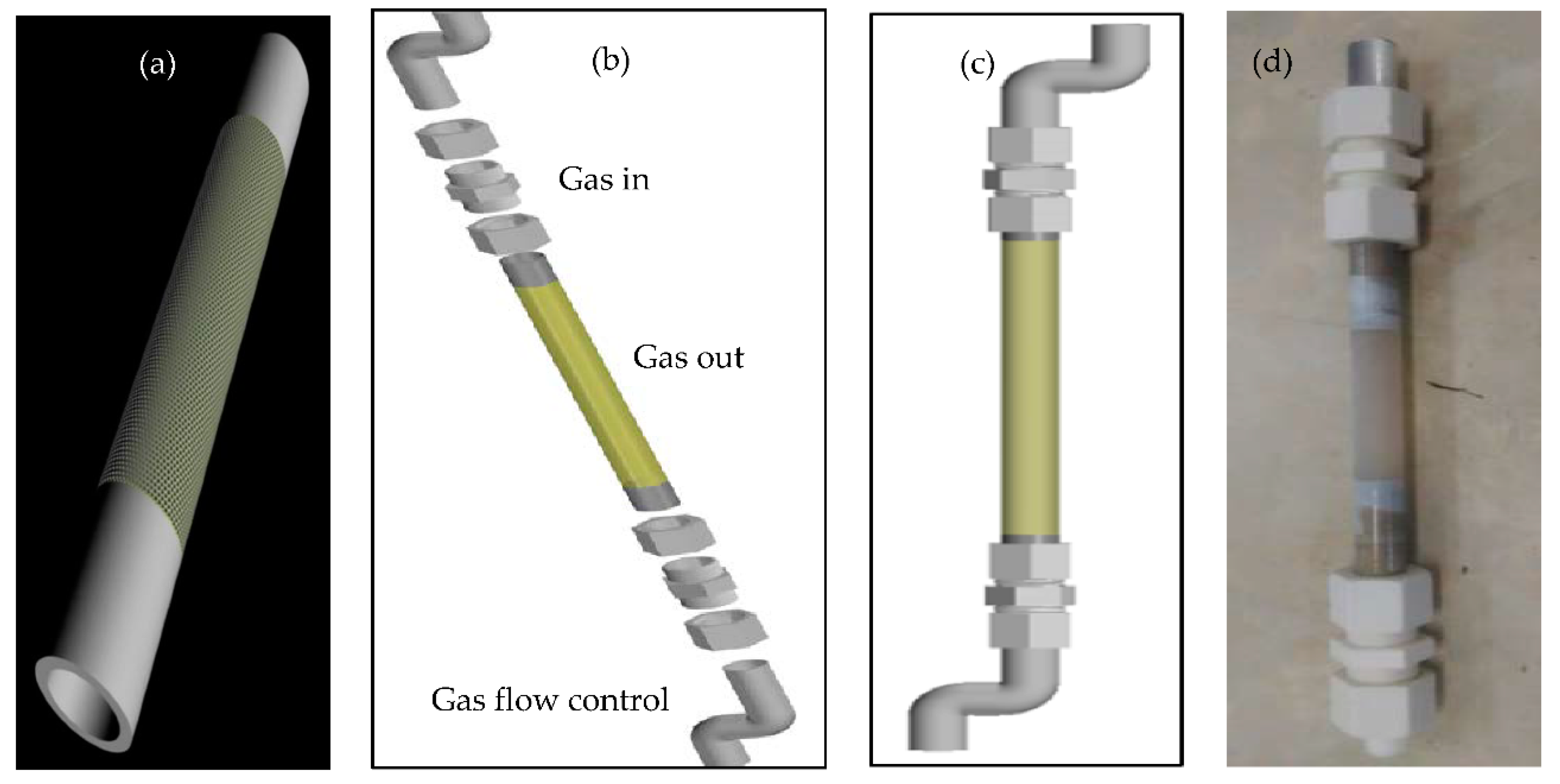
Figure 7 shows tubular AAO with Al connectors for the further characterizations of gas transmembrane pressure or liquid exudation tests. In Figure 7a, the schematic drawing of tubular AAO film with nano-channels structure is presented and both ends are connected with metal aluminum tubes. Figure 7b demonstrates the exploded view of a gas connector with tubular AAO, and the gas connectors on the tubular AAO in Figure 7c. The practical testing setup of gas connectors on the tubular AAO is shown in Figure 7d. For the pressure bearing testing of tubular AAO films, the barrier layer at the AAO bottom was kept, and then Ar gas was input into one of gas connector from the storage bottle, while the other end of gas connector was sealed. The pressure bearing capacity of tubular AAOs depended on their thickness. AAO film with a thickness of 100 μm can resist an argon pressure up to 8 atm; however, 30 μm AAO film can only withstand 3 atm of Ar gas. For the aeration test, AAO’s barrier layer was removed, and Ar gas was injected into one gas connector (the other one was sealed). As aerating tubular AAO was put in the water, a lot of bubbles leaked out on the AAO surface.
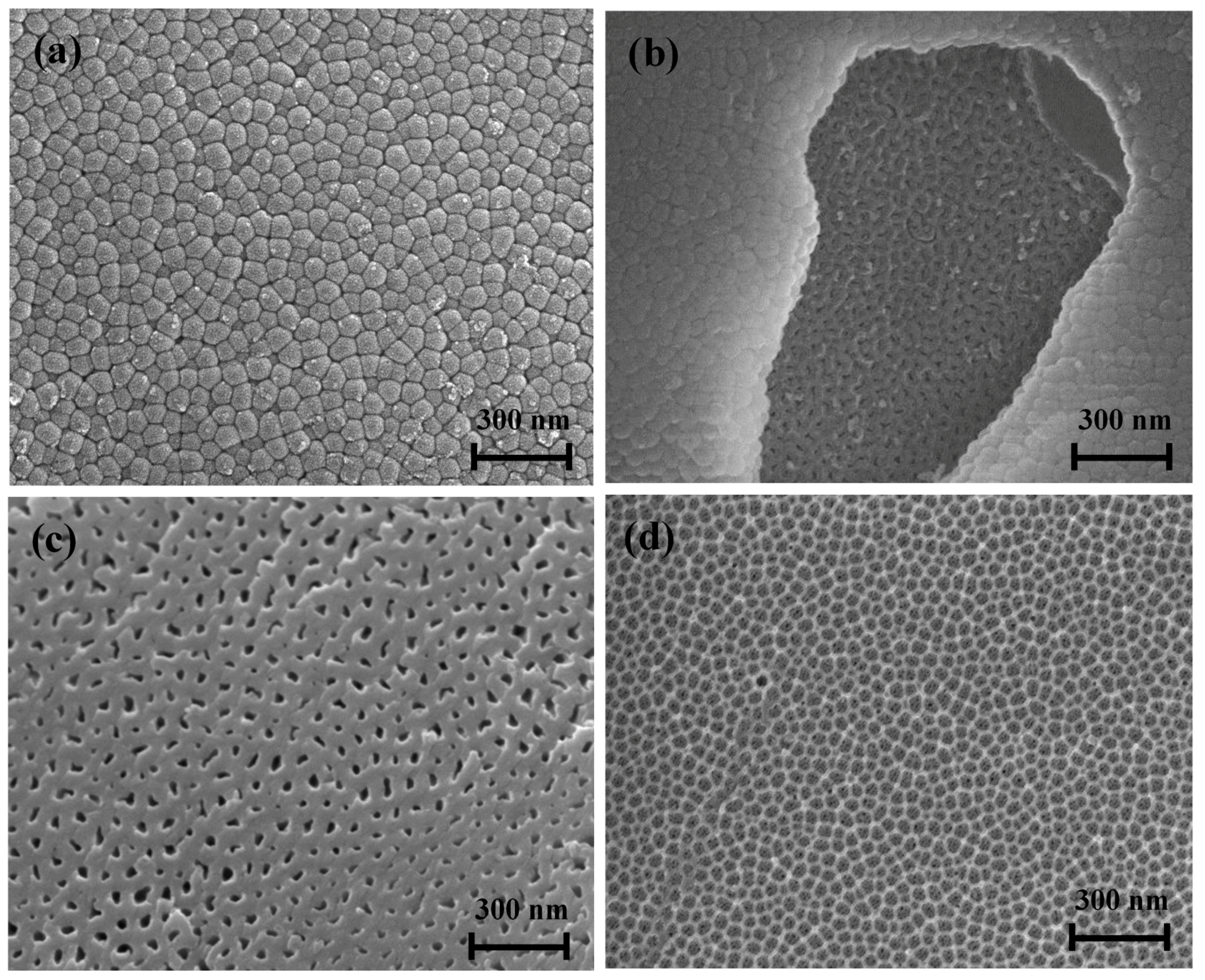
Figure 8 presents the SEM images of tubular AAO anodized at 40 V. In Figure 8a, a barrier layer having an ordered compact structure was observed at the bottom of the AAO. Figure 8b shows the nano-pores after partially removing the barrier layer. In Figure 8c, the entire barrier layer has been removed, and the bottom view image reveals the nano-pore structure. In Figure 8d, the average pore dimension is about 60 nm and the pore density is about 108–109 pore/cm2 in the AAO structure.
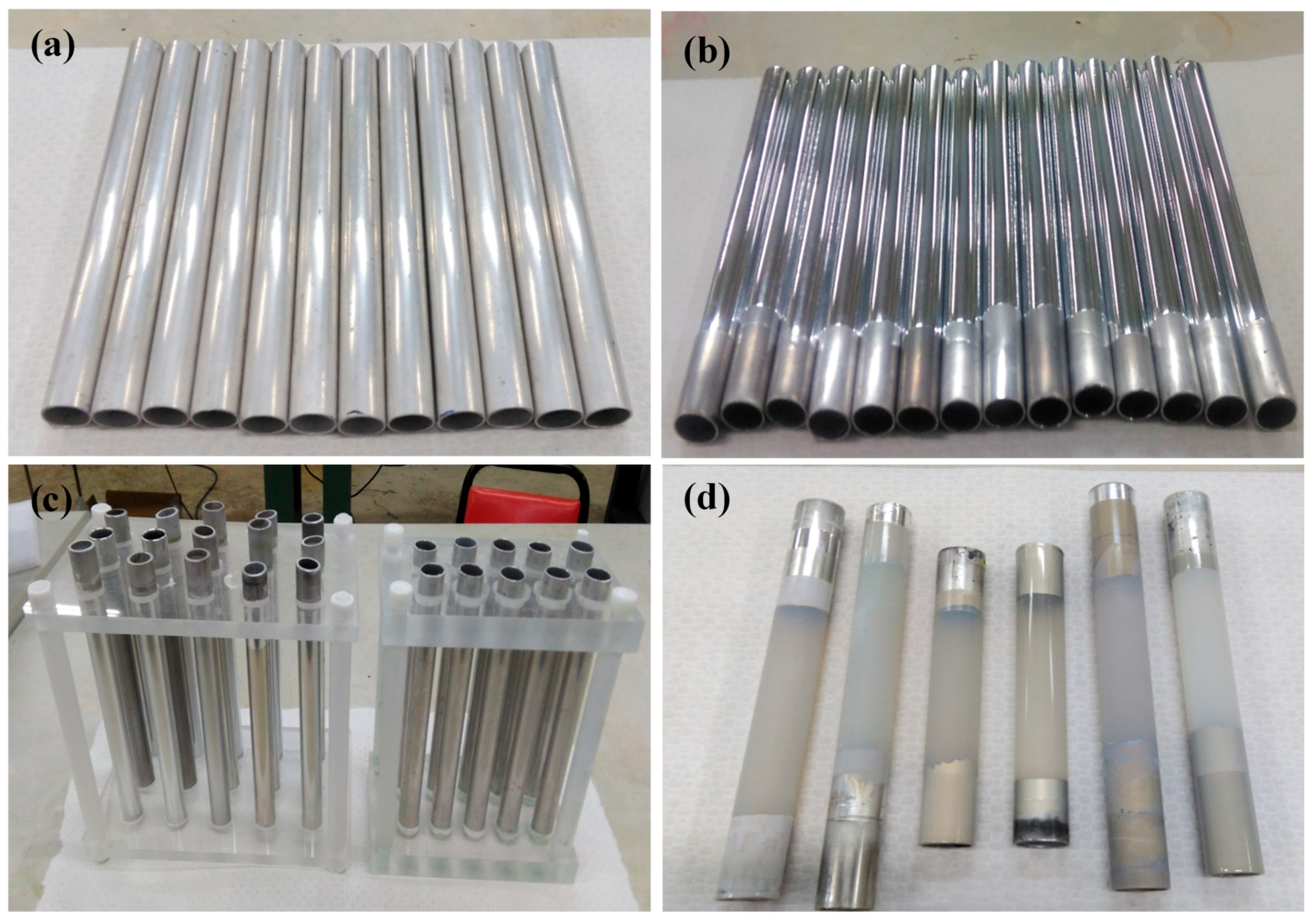
A complete tubular AAO process takes a long time, and the whole process includes (a) stress relief of Al tube (1 h); (b) mechanical grinding on the outer surface of the Al tube (1 h); (c) electrolytic polishing (10 min); (d) 1st anodization (1 h); (e) removal of 1st anodization film (50 min); (f) 2nd anodization (5 h); (g) removal of Al substrate (15 min); (h) removal of barrier layer (1 h); and, (i) pore widening (45 min). A complete tubular AAO process includes nine steps and takes around 10 h, at least. In order to increase the fabrication efficiency of tubular AAO a batch tubular AAO making is necessary. Figure 9 showed a batch tubular AAO process, including (a) a specified length of raw Al tubes is used; (b) a batch of mirror-like Al tubes surface formation after electrolytic polishing; (c) a batch of AAO production on the Al tubes through anodization; and, (d) a batch of tubular AAO formation after removing the retaining Al substrates. In our future work, high purity aluminum, such as 99.999% Al tubes will be used instead of 6061 Al for the AAO substrate. It is believed that the microstructure of the pore arrangement of AAO will thus be improved.
4. Conclusions
A new and simple method was developed, which enables a cost-effective approach for the fabrication of a batch of tubular AAO templates. According to the SEM images, the pore arrangement of AAO is far less dense than the hexagonal pore structure. Based on the tubular AAO process, high-purity (99.999%) Al can be used to synthesize AAOs with pore diameters that are smaller than 10 nm in H2SO4 electrolyte at a lower applied voltage (18 V) and pore diameters larger than 400 nm in H3PO4 electrolyte at high applied voltage (200 V).
The applications of tubular AAO films were also demonstrated via Ar gas bearing test and aeration test. Tubular AAO films with a thickness of 100 μm can resist a gas pressure of up to 8 atm, and the resistance was still as high as 3 atm, even the film thickness reduced to 30 μm. With a further perforation treatment, tubular AAO films became fluid-permeable. According to the aeration and ink exudation tests, both Ar gas and red ink could past through nano-structured AAO films slowly, suggesting to a potential candidate for in filtering, dialysis, and gas diffuser applications.
Author Contributions
S.H.C. and C.C.C. conceived and designed the experiments; C.W.H. performed the experiments; S.H.C. and Y.-J.C. analyzed the data; Z.L. contributed verifications of results; C.C.C. wrote the paper.
Funding
This research received no external funding.
Acknowledgments
This work was financially supported by the Ministry of Science and Technology Taiwan, under the Contract No. 106-2221-E-239-023.
Conflicts of Interest
The authors declare no conflict of interest.
References
- Chen, C.C.; Fang, D.; Luo, Z.P. Fabrication and Characterization of Highly-Ordered Valve-Metal Oxide Nanotubes and Their Derivative Nanostructures. Rev. Nanosci. Nanotechnol. 2012, 1, 229–256. [Google Scholar] [CrossRef]
- Ide, S.; Capraz, Ö.Ö.; Shrotriya, P.; Hebert, K.R. Oxide Microstructural Changes Accompanying Pore Formation during Anodic Oxidation of Aluminum. Electrochim. Acta 2017, 232, 303–309. [Google Scholar] [CrossRef]
- Jani, A.M.M.; Losic, D.; Voelcker, N.H. Nanoporous anodic aluminium oxide: Advances in surface engineering and emerging applications. Prog. Mater. Sci. 2013, 58, 636–704. [Google Scholar] [CrossRef]
- Wang, Y.; Kaur, G.; Chen, Y.; Santos, A.; Losic, D.; Evdokiou, A. Bioinert anodic alumina nanotubes for targeting of endoplasmic reticulum stress and autophagic signaling: A combinatorial nanotube-based drug delivery system for enhancing cancer therapy. ACS Appl. Mater. Interfaces 2015, 7, 27140–27151. [Google Scholar] [CrossRef] [PubMed]
- Nong, Y.L.; Qiao, N.N.; Deng, T.H.; Pan, Z.N.; Liang, Y. Solid sheet of anodic aluminium oxide supported palladium catalyst for Suzuki coupling reactions. Catal. Commun. 2017, 100, 139–143. [Google Scholar] [CrossRef]
- Park, I.J.; Choi, S.R.; Kim, J.G. Aluminum anode for aluminum-air battery—Part II: Influence of In addition on the electrochemical characteristics of Al-Zn alloy in alkaline solution. J. Power Sour. 2017, 357, 47–55. [Google Scholar] [CrossRef]
- Spooner, R.C. The Anodic Treatment of Aluminum in Sulfuric Acid Solutions. J. Electrochem. Soc. 1955, 102, 156–162. [Google Scholar] [CrossRef]
- Akahori, H. Electron Microscopic Study of Growing Mechanism of Aluminum Anodic Oxide Film. J. Electron Microsci. 1961, 10, 175–185. [Google Scholar]
- Mardilovich, P.P.; Govyadinov, A.N. New and modified anodic alumina membranes Part I. Thermotreatment of anodic alumina membranes. J. Membr. Sci. 1995, 98, 131–142. [Google Scholar] [CrossRef]
- Altuntas, S.; Buyukserin, F. Fabrication and characterization of conductive anodic aluminum oxide substrates. Appl. Surface Sci. 2014, 318, 290–296. [Google Scholar] [CrossRef]
- Belwalkar, A.; Grasing, E.; Geertruyden, W.V.; Huang, Z.; Misiolek, W.Z. Effect of processing parameters on pore structure and thickness of anodic aluminum oxide (AAO) tubular membranes. J. Membr. Sci. 2008, 319, 192–198. [Google Scholar] [CrossRef] [PubMed] [Green Version]
- Gong, D.; Yadavalli, V.; Paulose, M.; Pishko, M.; Grimes, C.A. Controlled Molecular Release Using Nanoporous Alumina Capsules. Biomed. Microdevices 2003, 5, 75–80. [Google Scholar] [CrossRef]
- Kasi1, A.K.; Kasi1, J.K.; Hasan, M.; Afzulpurkar, N.; Pratontep, S.; Porntheeraphat, S.; Pankiew, A. Fabrication of low cost anodic aluminum oxide (AAO) tubular membrane and their application for hemodialysis. Adv. Mater. Res. 2012, 550–553, 2040–2045. [Google Scholar] [CrossRef]
- Kasi, J.K.; Kasi, A.K.; Bokhari, M.; Sohail, M. Characterization of Cracks in Tubular Anodic Aluminum Oxide Membrane. Am. J. Condens. Matter Phys. 2016, 6, 36–40. [Google Scholar]
- Itoh, N.; Tomura, N.; Tsuji, T.; Hongo, M. Strengthened porous alumina membrane tube prepared by means of internal anodic oxidation. Microporous Mesoporous Mater. 1998, 20, 333–337. [Google Scholar] [CrossRef]
- Grimes, C.A.; Gong, D.W. Tubular Filter with Branched Nanoporous Membrane Integrated with a Support and Method of Producing Same. U.S. Patent 20030047505 A1, 13 March 2003. [Google Scholar]
- Yue, S.; Zhang, Y.; Du, J. Preparation of anodic aluminum oxide tubular membranes with various Geometries. Mater. Chem. Phys. 2011, 128, 187–190. [Google Scholar] [CrossRef]
- Chen, C.C.; Chang, S.F.; Luo, Z.P. Anodic-aluminum-oxide template assisted fabrication of cesium iodide (CsI) scintillator Nanowires. Mater. Lett. 2013, 112, 190–193. [Google Scholar] [CrossRef]
- Chen, C.C.; Bisrat, Y.; Luo, Z.P.; Schaak, R.E.; Chao, C.G.; Lagoudas, D.C. Fabrication of Single Crystal tin Nanowires by Hydraulic Pressure Injection. Nanotechnology 2006, 17, 367–374. [Google Scholar] [CrossRef]
- Chen, P.C.; Hsieh, S.J.; Chen, C.C.; Zou, J. The Microstructure and Capacitance Characterizations of Anodic Titanium Based Alloy Oxide Nanotube. J. Nanomater. 2013, 2013. [Google Scholar] [CrossRef]
- Chen, M.S.; Fan, F.Y.; Lin, C.K.; Chen, C.C. Enhanced Diffusion Bonding Between High Purity Aluminum and 6061 Aluminum by Electrolytic Polishing Assistance. Int. J. Electrochem. Sci. 2016, 11, 4922–4929. [Google Scholar] [CrossRef]
- Chen, C.C.; Chang, S.F.; Li, L.L.; Chou, C.Y.; Yang, H.W. A Tubular Solar Cell. TW Patent I590502, 14 November 2016. [Google Scholar]
Figure 1.
Schematic diagram of the producing flow and instrument setup with an overhead conductive rod for fabricating the tubular anodic aluminum oxide (AAO) template. The operating process is conducted in the order from (a–f), but after each step, the sample is rinsed in (b) the water bath. The solutions in the tanks are (a) electro-polishing electrolyte; (b) water; (c) anodization electrolyte; (d) AAO removal solution; (e) aluminum removal solution; and, (f) AAO pore widening solution.

Figure 2.
(a) Schematic diagram and (b) working situation of experimental setup for removing aluminum substrate from Al/AAO sample.
Figure 2.
(a) Schematic diagram and (b) working situation of experimental setup for removing aluminum substrate from Al/AAO sample.

Figure 3.
Optical images of tubular Al/AAO film after etching Al substrate for (a) 2 min; (b) 4 min; (c) 6 min; (d) 8 min; (e) 10 min; (f) 12 min; (g) 15 min; and, (h) the finish product cleaned with water.
Figure 3.
Optical images of tubular Al/AAO film after etching Al substrate for (a) 2 min; (b) 4 min; (c) 6 min; (d) 8 min; (e) 10 min; (f) 12 min; (g) 15 min; and, (h) the finish product cleaned with water.

Figure 4.
Step-by-step images of tubular AAO fabrication process: (a) initial 6061 Al tube and their outward appearances after each procedures, including (b) mechanical grinding; (c) electrolytic polishing; (d) the first anodization; (e) ordering pattern; and, (f) the second anodization; and, (g) the finished tubular AAO film with Al rings on both ends.

Figure 5.
Schematic diagram of tubular AAO micro-morphology; (a) AAO film on the aluminum substrate and its (b) enlarged image; AAO film (c) without aluminum substrate; and, (d) barrier layer.
Figure 5.
Schematic diagram of tubular AAO micro-morphology; (a) AAO film on the aluminum substrate and its (b) enlarged image; AAO film (c) without aluminum substrate; and, (d) barrier layer.

Figure 6.
Photos of tubular AAO film formed from 6061 Al tubes: (a) raw 6061 Al tube material; (b) electro-polished (EP) 6061 Al; (c) AAO formation on the 6061 Al tube; (d) partially removed 6061 Al substrate from AAO film; (e) tubular AAO film without 6061 Al substrate; and, (f) red ink exudation through AAO film.

Figure 7.
The schematic diagram of transmembrance pressure test on the tubular AAO; (a) tubular AAO; (b) exploded view of gas connector with tubular AAO; (c) gas connector with tubular AAO; and, (d) image of gas connector with tubular AAO.
Figure 7.
The schematic diagram of transmembrance pressure test on the tubular AAO; (a) tubular AAO; (b) exploded view of gas connector with tubular AAO; (c) gas connector with tubular AAO; and, (d) image of gas connector with tubular AAO.

Figure 8.
Scanning electron microscope (SEM) images of tubular AAO microstructure; (a) bottom view of barrier layer; (b) partially removed barrier layer; (c) bottom view without barrier layer; and, (d) top view of nano-pores.
Figure 8.
Scanning electron microscope (SEM) images of tubular AAO microstructure; (a) bottom view of barrier layer; (b) partially removed barrier layer; (c) bottom view without barrier layer; and, (d) top view of nano-pores.

Figure 9.
Batch tubular AAO process (a) 6061 Al tubes; (b) electrolytic polished 6061 Al tubes; (c) anodized 6061 Al tubes; and, (d) tubular AAO films.
Figure 9.
Batch tubular AAO process (a) 6061 Al tubes; (b) electrolytic polished 6061 Al tubes; (c) anodized 6061 Al tubes; and, (d) tubular AAO films.

© 2018 by the authors. Licensee MDPI, Basel, Switzerland. This article is an open access article distributed under the terms and conditions of the Creative Commons Attribution (CC BY) license (http://creativecommons.org/licenses/by/4.0/).
Share and Cite
MDPI and ACS Style
Hun, C.W.; Chiu, Y.-J.; Luo, Z.; Chen, C.C.; Chen, S.H. A New Technique for Batch Production of Tubular Anodic Aluminum Oxide Films for Filtering Applications. Appl. Sci. 2018, 8, 1055. https://doi.org/10.3390/app8071055
AMA Style
Hun CW, Chiu Y-J, Luo Z, Chen CC, Chen SH. A New Technique for Batch Production of Tubular Anodic Aluminum Oxide Films for Filtering Applications. Applied Sciences. 2018; 8(7):1055. https://doi.org/10.3390/app8071055
Chicago/Turabian StyleHun, Chien Wan, Yu-Jia Chiu, Zhiping Luo, Chien Chon Chen, and Shih Hsun Chen. 2018. "A New Technique for Batch Production of Tubular Anodic Aluminum Oxide Films for Filtering Applications" Applied Sciences 8, no. 7: 1055. https://doi.org/10.3390/app8071055
Note that from the first issue of 2016, this journal uses article numbers instead of page numbers. See further details here.