Effects of Thermal Frequency on Microstructures, Mechanical and Corrosion Properties of AA6061 Joints


School of Mechanical and Automotive Engineering, South China University of Technology, Guangzhou 510000, China
*
Author to whom correspondence should be addressed.
Appl. Sci. 2018, 8(4), 540; https://doi.org/10.3390/app8040540
Submission received: 9 March 2018
/
Revised: 24 March 2018
/
Accepted: 27 March 2018
/
Published: 2 April 2018
Abstract
:Three thermal frequencies that were designated as 3, 4, and 5 Hz were used to reveal the microstructural evolution, mechanical, and corrosion properties of AA6061-T6 sheets that were welded by double pulsed gas metal arc welding (DP-GMAW) using microstructural observations, microhardness tests, tensile tests, bend tests, impact tests, and corrosion tests. A self-developed welding system consisted of a digital multifunctional welder and an arc dynamic waveform wavelet analyzer was chosen to perform welding operations and to record electrical signal waveforms during the welding process. The results show that the process of DP-GMAW was stable, and the weld beads exhibited aesthetic ripples. The ripple distance, the grain size, and porosity of the fusion zone decreased with an increasing thermal frequency. Microhardness and corrosion properties of the weld joint improved when the thermal frequency increased. In addition, all of the joints exhibited excellent bending properties. However, the impact property of the weld joint was lower than that of the BM. It indicated that the low impact energy results of the welded AA6061-T6 sheet were mainly due to the formation of micro-cracks in the fusion zone.
1. Introduction
Aluminum alloys have been extensively applied in automobiles, high-speed trains, naval vessels, and the aerospace industry due to the advantages of lightweight, excellent corrosion resistance, splendid impact resistance, and convenient to recycle [1,2,3]. Along with the increasing demand of improving the processing quality of aluminum alloys, new welding methods continuously appear, such as double pulsed gas metal arc welding (DP-GMAW), cold arc welding, friction stir welding, cold metal transfer welding, and laser hybrid welding [4,5,6,7,8]. Among all of these methods, DP-GMAW has garnered increasing attentions due to its low cost, high productivity, and perfect welding quality [9].
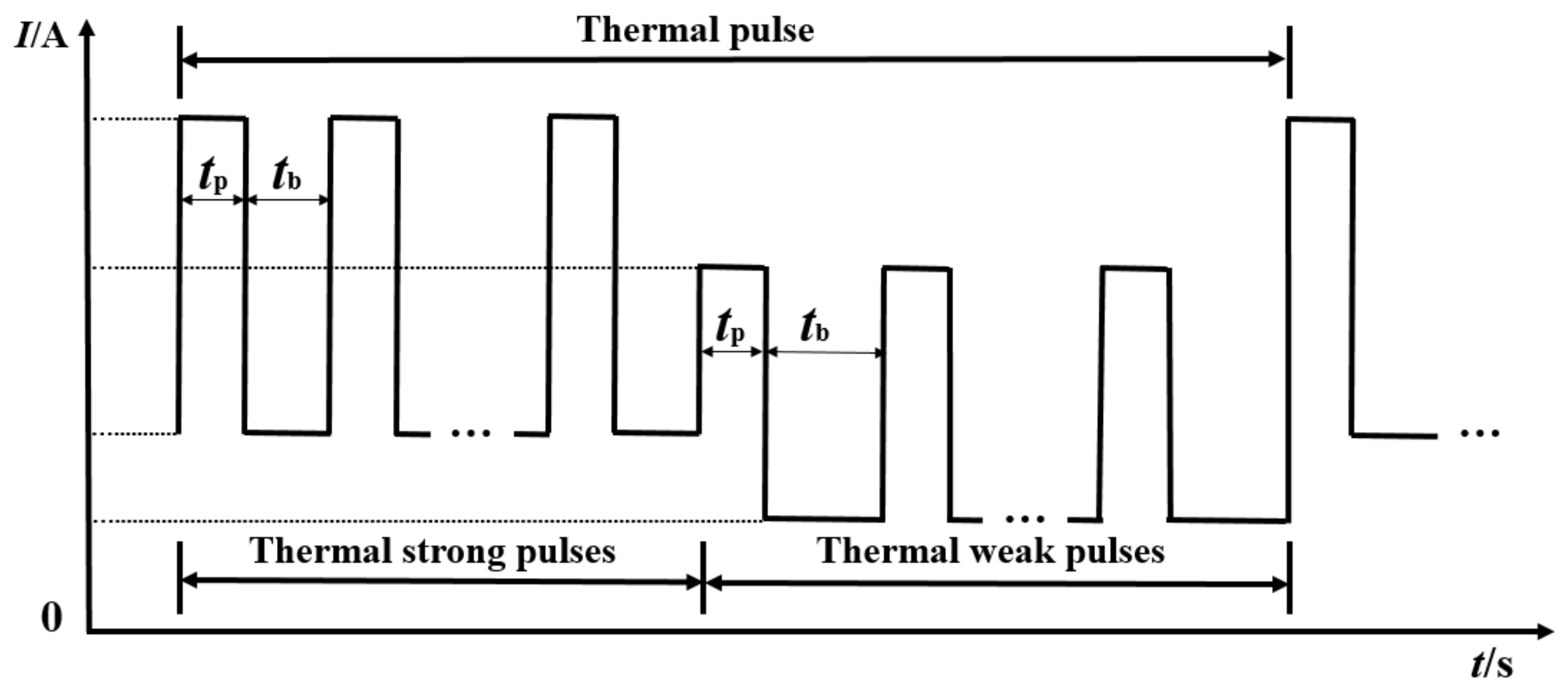
DP-GMAW is a variant of the conventional pulsed GMAW, which is now used in a extensive range of applications [10,11]. The current waveform of DP-GMAW is shown in Figure 1. The main characteristic of DP-GMAW is the coexistence of high frequency and thermal frequency [12]. The thermal pulse consists of an array of thermal strong pulses and an array of thermal weak pulse. The role of high frequency (1/(tp + tb)) is keeping the one droplet per pulse mode throughout the DP-GMAW process, and the role of thermal frequency is modulating the peak value and the time of the high frequency pulse to stir the weld pool [13]. During the DP-GMAW process, the arc force and heat input are varied with the thermal frequency. This can effectively control the amount of heat input and improve the overall performance of welded joints with the formation of continuous and aesthetic welding ripples [14].
When compared with the traditional GMAW and pulsed GMAW, the merits of DP-GMAW can be summarized as follows: a wider adjusted welding current range, a wider joint gap configuration, less heat input, less porosity incidence, and crack sensitivity [15]. Mendes da Silva et al. [13] made a systematic study on porosity formation mechanism and crack sensitivity in the P-GMAW and DP-GMAW process. It was concluded that DP-GMAW could decrease the porosity susceptibility and reduce welding crack sensitivity. Liu et al. [16] revealed the influence of aging treatment on AA7075-T651 aluminum alloy joints by DP-GMAW. It was found that the microstructure of weld was improved obviously after the heat treatment of welding joints, meanwhile both the microhardness and tensile properties of welded joints were enhanced. Yi et al. [17] investigated the temperature field and the stress-strain field of the 6061-T6 aluminum alloy sheet T-joints by DP-GMAW. The results showed that the residual stress of T-joint was mainly concentrated in the welding seams. The molten pool temperature in weak pulse group period was relatively low and the volume was smaller, while the stress of the molten pool and the surrounding metal was relatively higher. Yao et al. [18] reported the effect of average current, high frequency, thermal frequency, and welding velocity on the microstructure of aluminum alloy joints using the DP-GMAW process. Mathivanan et al. [19] made a comparison between DP-GMAW and pulsed GMAW on mechanical and metallurgical properties. The results showed that the joints of DP-GMAW had superior microhardness and tensile properties.
The above-mentioned investigations about the DP-GMAW are mainly focused on the effect of welding parameters on the microstructures or mechanical properties of the aluminum alloy welded joints. However, the impact mechanism of thermal frequency on the aluminum alloy joints using DP-GMAW is still not thorough. The optimum thermal frequency must be found to provide acceptable weld bead shape, suitable microstructures, and appropriate mechanical and corrosion resistance for the welding process. Hence, in the current paper, the effect of thermal frequency on the microstructural evolution (porosity and grain size), microhardness, the mechanical properties (tensile, impact, and bend), and corrosion behavior of DP-GMA welded AA6061-T6 aluminum alloy joints are investigated.
2. Materials and Methods
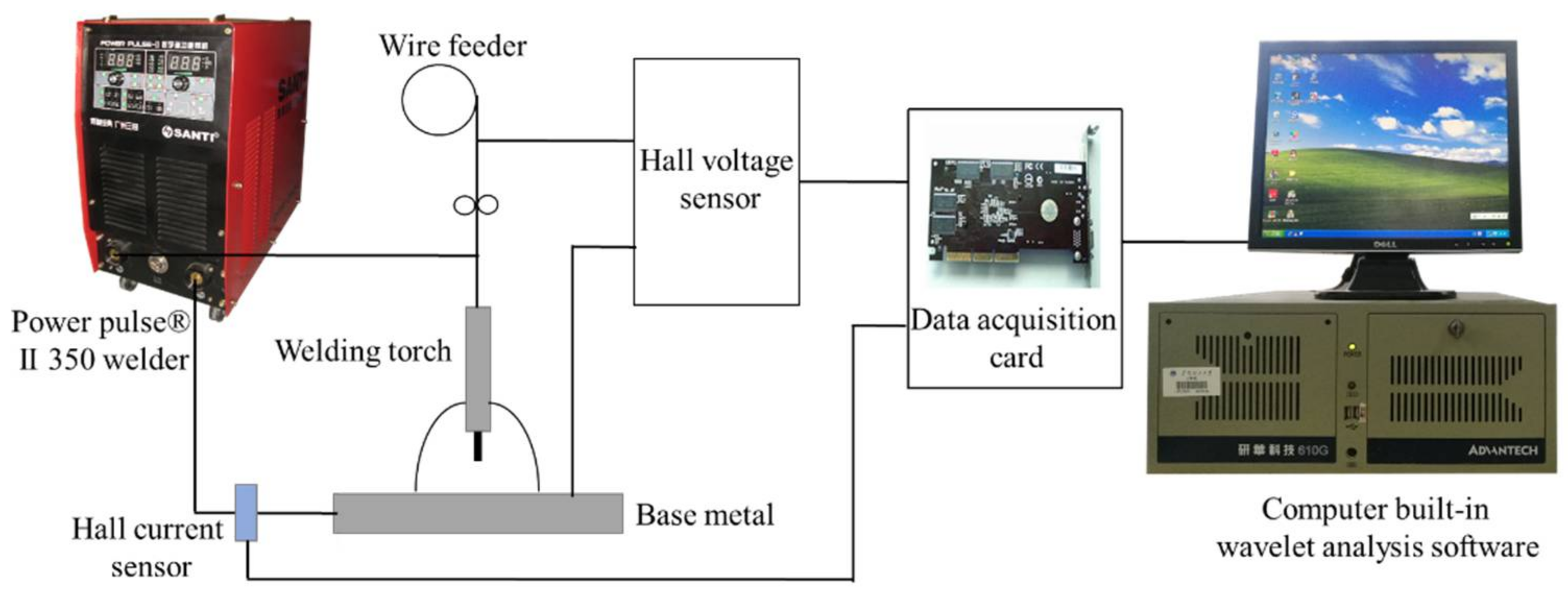
The workpiece in current study was AA6061-T6 aluminum alloy sheet with dimensions of 300 mm × 60 mm × 3 mm. Its tensile strength was 327 MPa. A butt joint was prepared. The ER4043 and pure argon were, respectively, selected as the filler wire and the shielding gas for the DP-GMAW process. The self-developed digital welding machine, named Power Pulse® II 350, was adopted as the welding power source to carry out the DP-GMAW by programming. Prior to welding, the surfaces of the aluminum alloy sheet were scratched by a steel brush and cleaned by acetone to prevent the effect of oil, oxides, and water. Table 1 shows the chemical compositions of base metal and filler wire. Table 2 shows the main welding parameters of DP-GMAW. Electrical signals throughout the experiment were collected and were disposed for offline analysis by the arc dynamic waveform wavelet analyzer [20]. The experimental setup of the current research is shown in Figure 2.
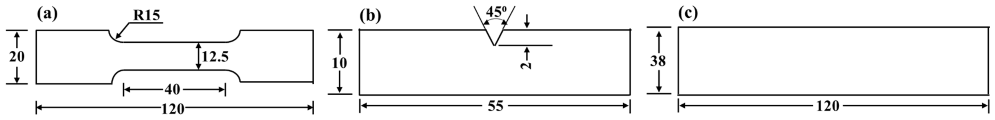
After the DP-GMAW, metallographic specimens, tensile specimens, microhardness specimens, impact specimens, bend specimens, and corrosion specimens were obtained from each butt welded sheet by the electric cutting machine STDX600. The cutting of all the specimens was perpendicular to the weld, except for the specimens that were used for the inspection of porosity. The dimensions of specimens are shown in Figure 3. The metallographic specimens were prepared by standard metallographic procedures. The microstructure character of the welded joints was analyzed by the optical microscope (OM) (Carl Zeiss AG, Heidenheim, Germany), the scanning electron microscope (SEM) (Hitachi, Tokyo, Japan), and the energy dispersive spectrometer (EDS) (Krates, Manchester, UK). Vickers microhardness tests were carried out on polished and etched specimens with a period of 15 s, a load of 200 g, and a step size of 1 mm. The room temperature tensile and bend tests were carried out on an AG-IC tensile machine (SHIMADZU, Kyoto, Japan). Charpy impact specimens (thickness of 3 mm) were prepared to evaluate the impact toughness of the welded joints. When the tensile tests and impact tests were finished, the fracture morphology of welded joints was observed using SEM.
Tensile test specimens for the AA6061-T6 sheet and the welded joint were produced following ASTM E8. Bent tests were conducted in accordance with ASTM E290, and Charpy impact test samples were prepared in accordance with ISO 5173:2000.
3. Results and Analysis
3.1. Welding Process Stability
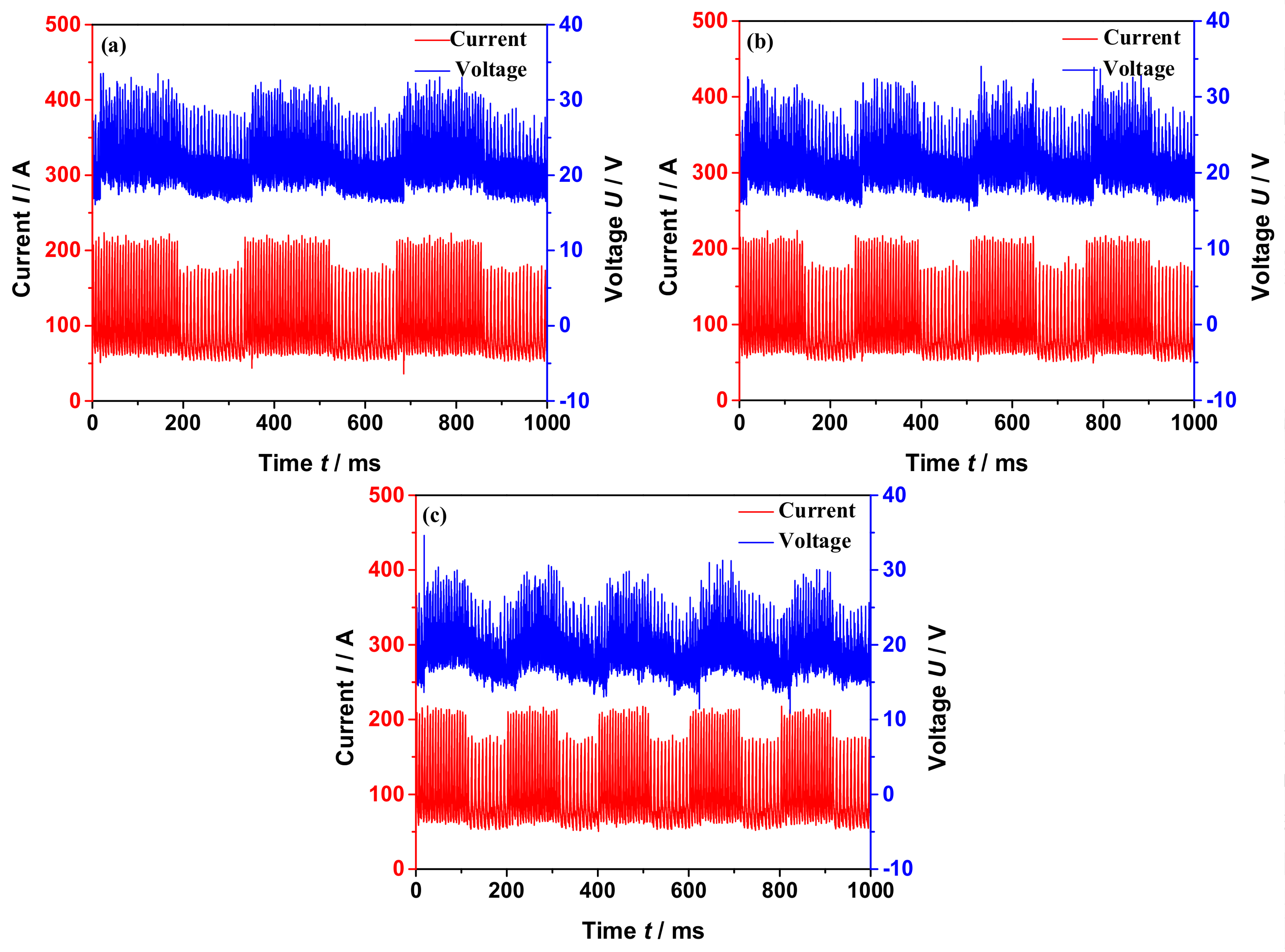
The transient current and voltage waveforms in DP-GMAW with a thermal frequency of 3, 4, and 5 Hz are shown in Figure 4. All of the welding processes were successfully finished. According to Figure 4, the transient electrical waveform, which consists of an array of thermal strong pulses and an array of thermal weak pulses in one cycle, are repeatable and smooth. The difference between the peak current of thermal strong pulse and the peak current of thermal weak pulse is 40 A, according to Yao [18]. Neither short circuit nor broken circuit appears in the smooth and periodic curve waveforms, which indicates a smooth current transition during DP-GMAW welding. Besides, the stability of transient voltage waveform correlates to the regularity of transfer droplet [21].
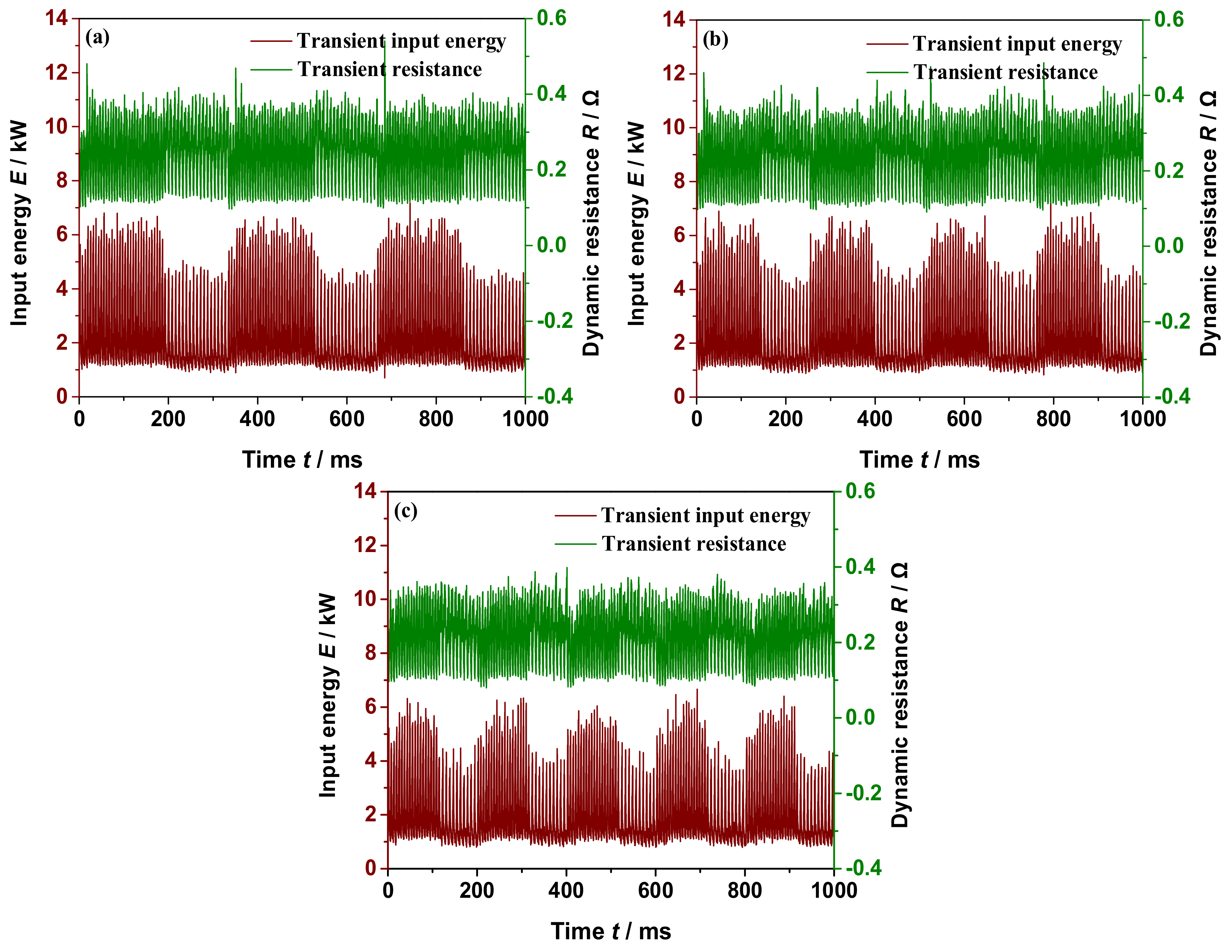
The transient input energy and transient resistance waveforms in DP-GMAW welding with thermal frequency of 3, 4, and 5 Hz are shown in Figure 5. Both input energy and dynamic resistance are the product of transient current and transient voltage. Similarly it is found that their waveforms consist of an array of strong pulses and an array of weak pulses in one period of the DP-GMAW process. It should be noticed that when the waveform of current is on wave crest (wave trough), the waveform of input energy was also on wave crest (wave trough). In addition, it can be seen that the transient dynamic resistance waveform mainly varies in the narrow range of 0.1~0.4 Ω. Also, when the thermal frequency is varied from 3 Hz to 5 Hz, the transient input energy waveform fluctuates in the concentrated range of 1~7 kW with good repeatability, which indicates that the process of DP-GMAW welding is stable without short circuit and arc extinguishing.
3.2. Weld Bead Shape and Porosity
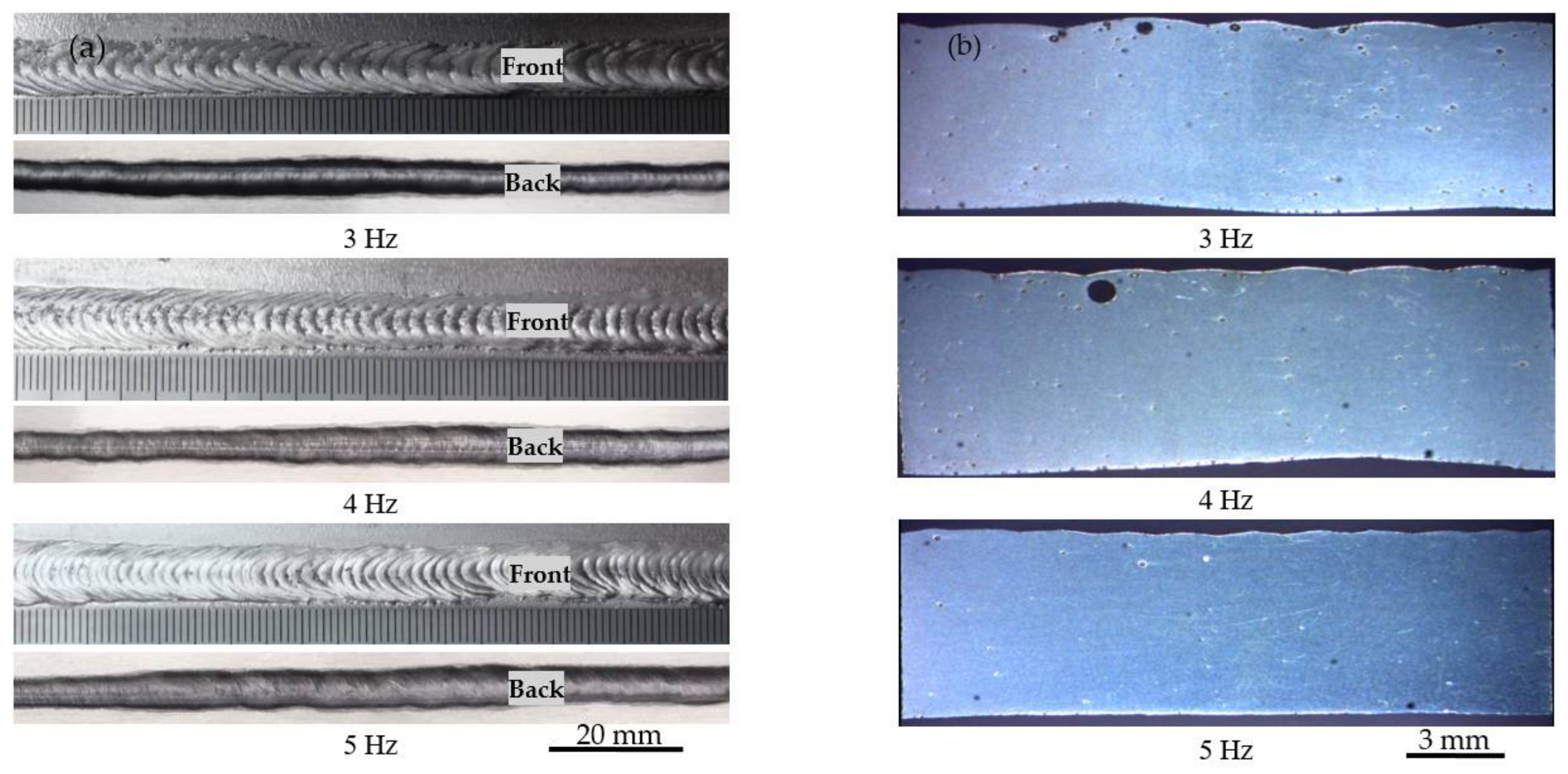
The weld beads are shown in Figure 6a. It is found that the weld beads are perfectly formed in each thermal frequency without spatter, undercut, and collapsing. The typical ripples are formed on the front surface of weld bead. The distance between the adjacent ripples becomes wider, when the thermal frequency is lower, therefore, the shape of the weld bead becomes successively smoother in the longitudinal section as the pulse frequency is increased from 3 Hz to 5 Hz.
In the solidification process of welding pool, the gas dissolving in liquid metal escapes from the molten pool through three stages of nucleation, growth, and floating. If the solidification rate of the molten pool is faster than the gas rate of nucleation, growth, and rising, then the weld bead will have residual pores. Distribution of porosity on longitudinal section weld bead processed at different thermal frequencies are shown in Figure 6b. Macrostructure details and porosity of weld beads are presented in Table 3. It is observed that the welding parameters for different thermal frequencies could gain access to a full penetration of 6061-T6 welds with no crack. There will be more porosity being contained in the weld bead when the thermal frequency becomes lower. It reveals that the higher thermal frequency can improve the fluidity of the molten pool, which is beneficial to the gas escaping. Further analysis shows that the thermal frequency of 5 Hz has a result in a higher W/D ratio than the thermal frequency of 3 Hz and 4 Hz due to the strong stirring effect. A higher W/D ratio means a better escapement of gas, which is in agreement with the report by Pal [22].
3.3. Microstructures of the Welded Joints
Figure 7 shows the microstructure of the fusion zone welded at 3, 4, and 5 Hz. It is observed that the grain size at 5 Hz is smaller, the grain size at 3 Hz is bigger, and the grain size at 4 Hz is in the middle. The reason for this phenomenon may be that the weld pool is periodically stirred by the thermal frequency, thereby the fluidity of the weld pool is improved by increasing the thermal frequency and the growth of grains is simultaneously inhibited [23].
Liu et al. demonstrated that the arc length varied with thermal frequency [9]. The welding arc changing periodically, the welding arc makes the heat input and the arc force to vary in alternating high and low, which cause the oscillation of the weld pool. The oscillation of the molten pool is beneficial to the spillover of the bubbles in the molten pool and the refinement of grains, thus improving the quality of the welded joint [24,25]. As soon as the varied weld pool size reaches a value where the intrinsic oscillation frequency of the weld pool is equal to the thermal frequency of DP-GMAW, the weld pool will be in resonance, with the pool oscillation amplitude reaching the maximum and the fusion zone obtaining the most refinement grain.
When compared to 3 Hz and 4 Hz, the smaller gain size of fusion zone is obtained at 5 Hz. It is illustrated that the oscillation frequency of the molten pool at 5 Hz is closer to the intrinsic frequency of the molten pool. Smaller grain size may markedly lead to less porosity and crack sensitivity, which enhances the mechanical properties of the weld. Therefore, the thermal frequency of 5 Hz is more suitable for the welding of AA6061-T6 aluminum alloy.
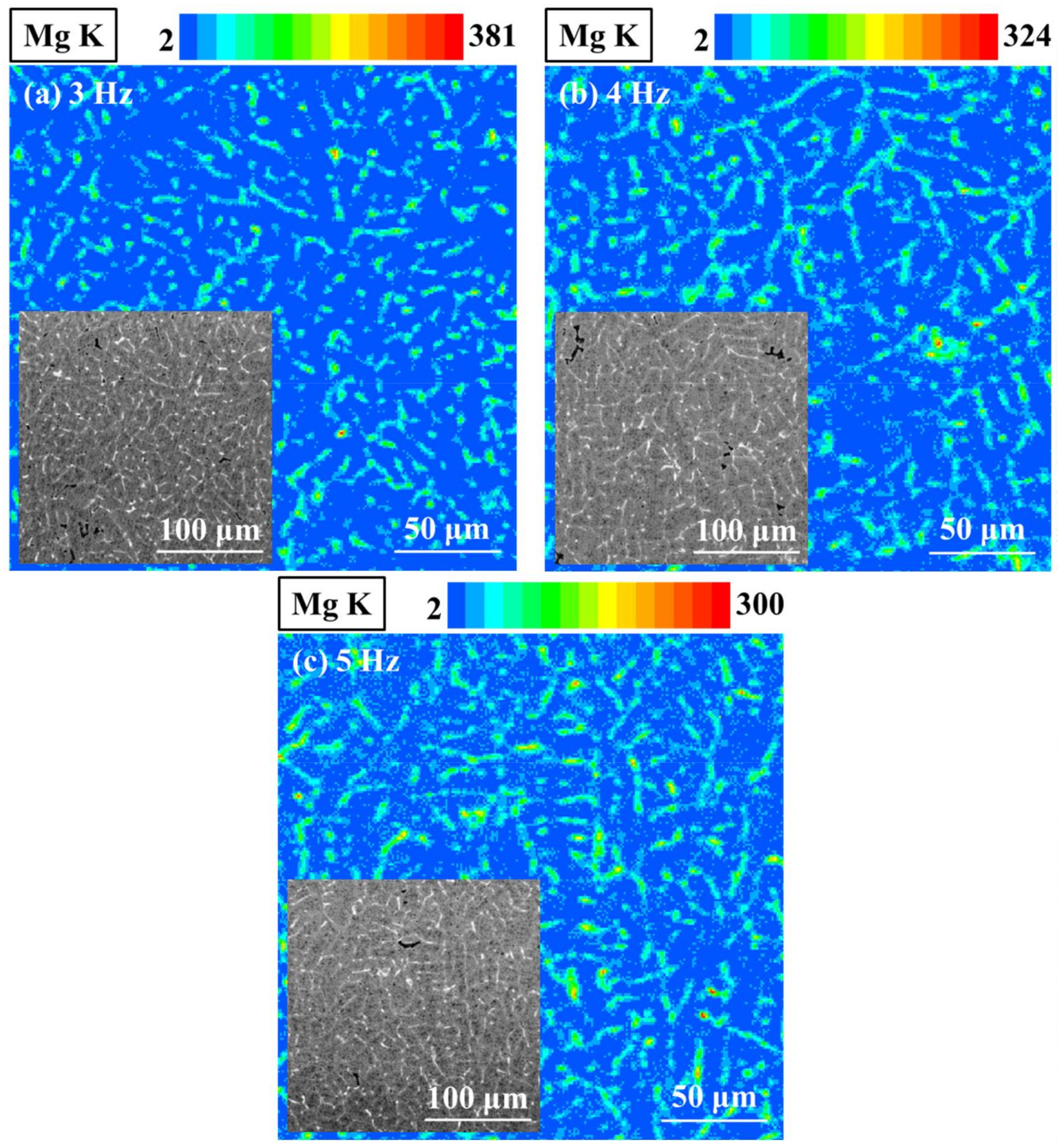
In the Al-Mg-Si alloy, the Mg2Si precipitate significantly influences the microhardness and the mechanical properties of welded joints, and the distribution of magnesium element greatly affects the formation of Mg2Si precipitate [26]. The EDS maps of Magnesium elemental in fusion zone is shown in Figure 8. It can be noticed that the distribution areas of magnesium at 3 Hz are sparser than that of 4 Hz and 5 Hz, and the content of magnesium at 3 Hz is higher than that of 4 Hz and 5Hz. The results indicate the more Mg2Si precipitate are distributed in the matrix when the thermal frequency is higher, therefore, thermal frequency significantly affects the precipitation of Mg2Si.
3.4. Microhardness
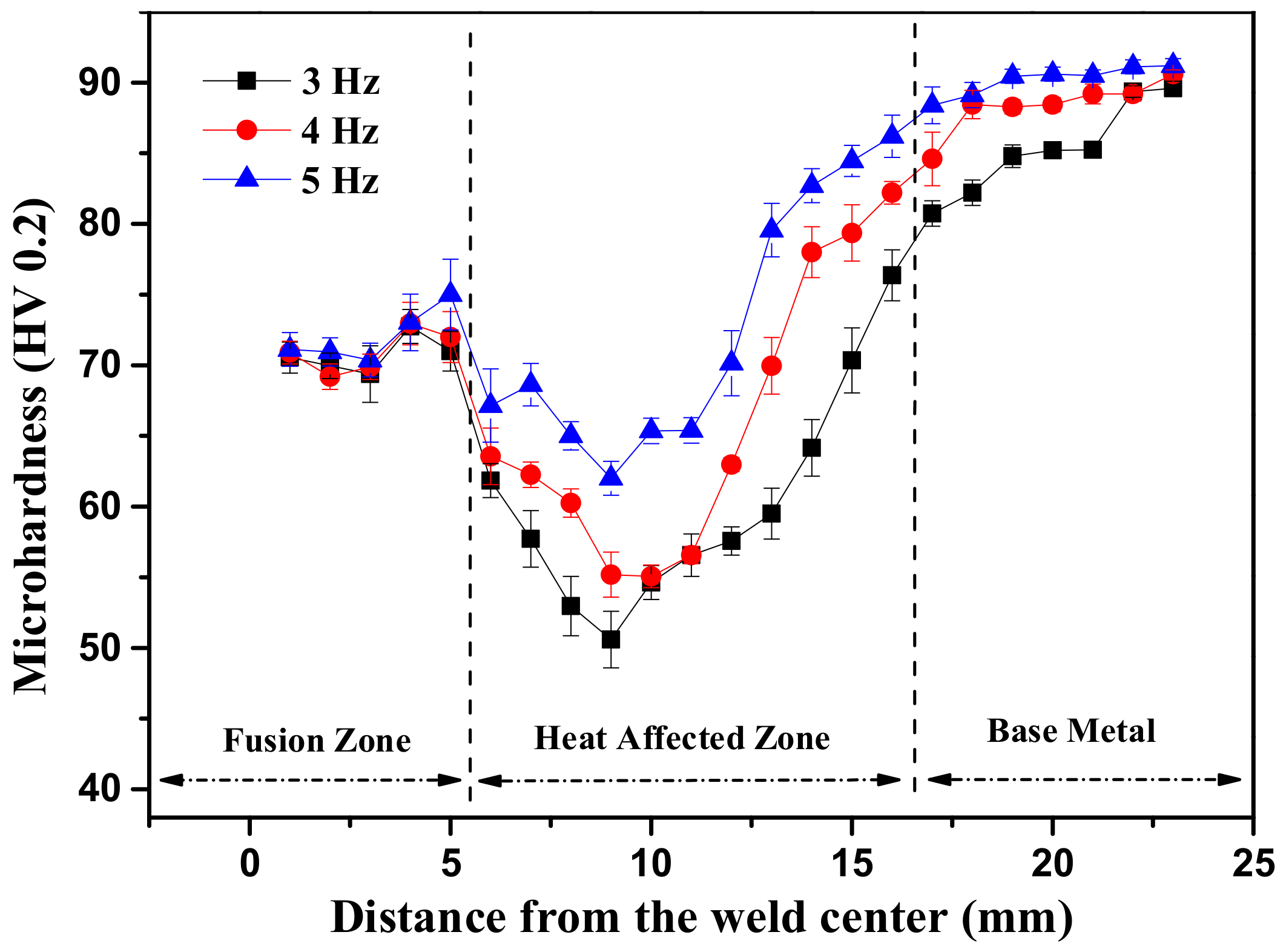
The hardness level of aluminum alloys is mainly determined by the strength of precipitate. Figure 9 shows the Vickers micro-hardness values of AA6061-T6 aluminum alloy joints that are welded at 3, 4, and 5 Hz. It is found from Figure 9 that the highest hardness is got in the base metal, while the lowest hardest value occurs in the heat affected zone. The softening in the heat affected zone of AA6061-T6 aluminum alloy is mainly due to the dissolution of strengthened Mg2Si precipitates [27,28]. As shown in Figure 9, the Vickers microhardness of welded joint becomes higher when the thermal frequency is higher. With the thermal frequency increasing from 3 Hz to 5 Hz, the stirring effect of thermal frequency on weld pool is improved, the grain size is refined, and porosity and crack sensitivity decreases. Therefore, the microhardness property of welded joint is improved. According to Hall-Petch relation [21], smaller grain size leads to larger yield strength. As studied in Figure 7, the grain size for 5 Hz is smaller than that of other situations, which leads to higher yield strength, as shown in Figure 10.
3.5. Mechanical Properties
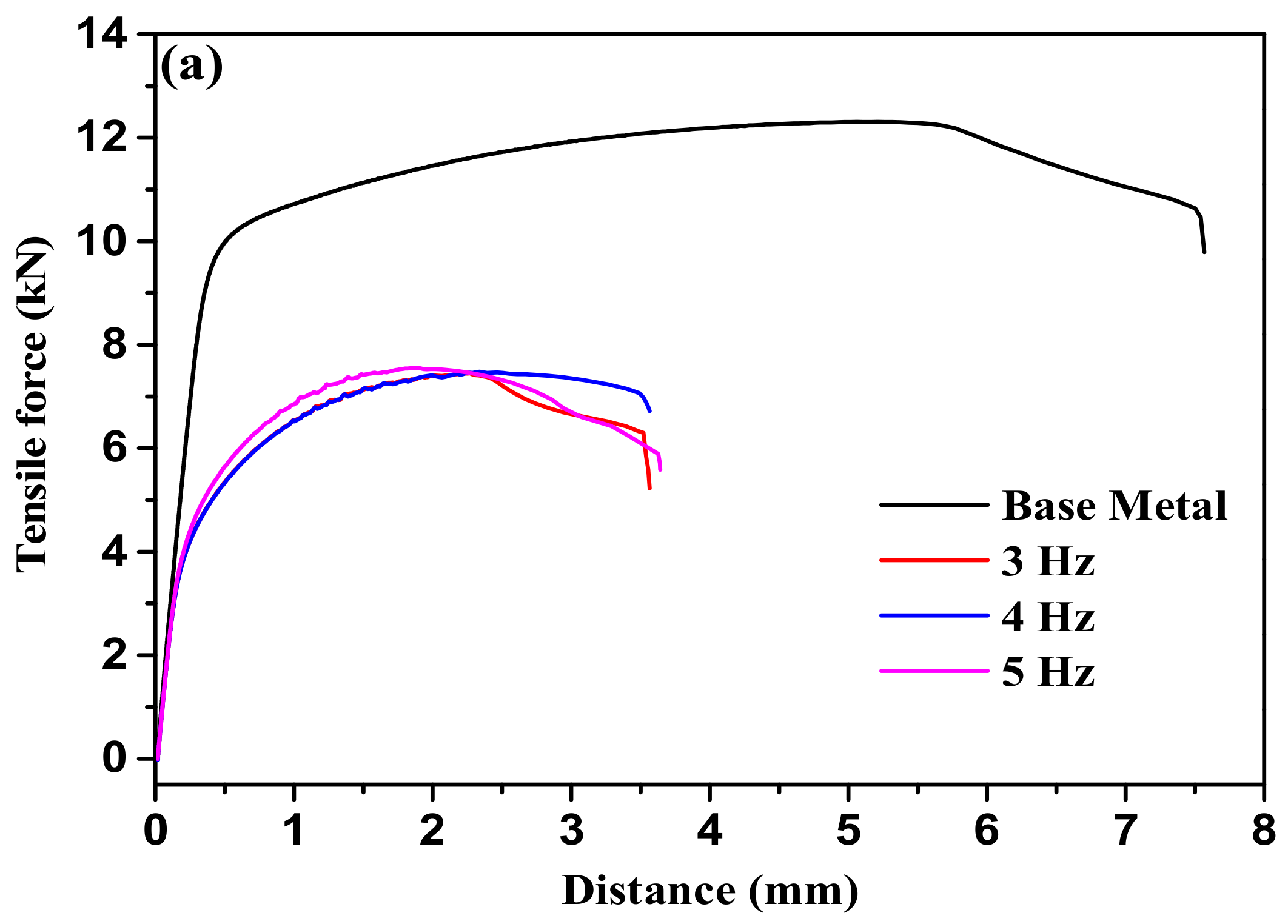
Figure 10a shows the tensile curves of the welded joints. Figure 10b shows that the yield and the tensile strength of the base metal are 242 MPa and 327 MPa, respectively, and that the elongation is about 16.9%. The yield strength, tensile strength, and elongation of the welded joint are much weaker than that of the base metal. For three kinds of welded joints at 3, 4, and 5 Hz, there is no significant difference in tensile strength, yield strength, and elongation.
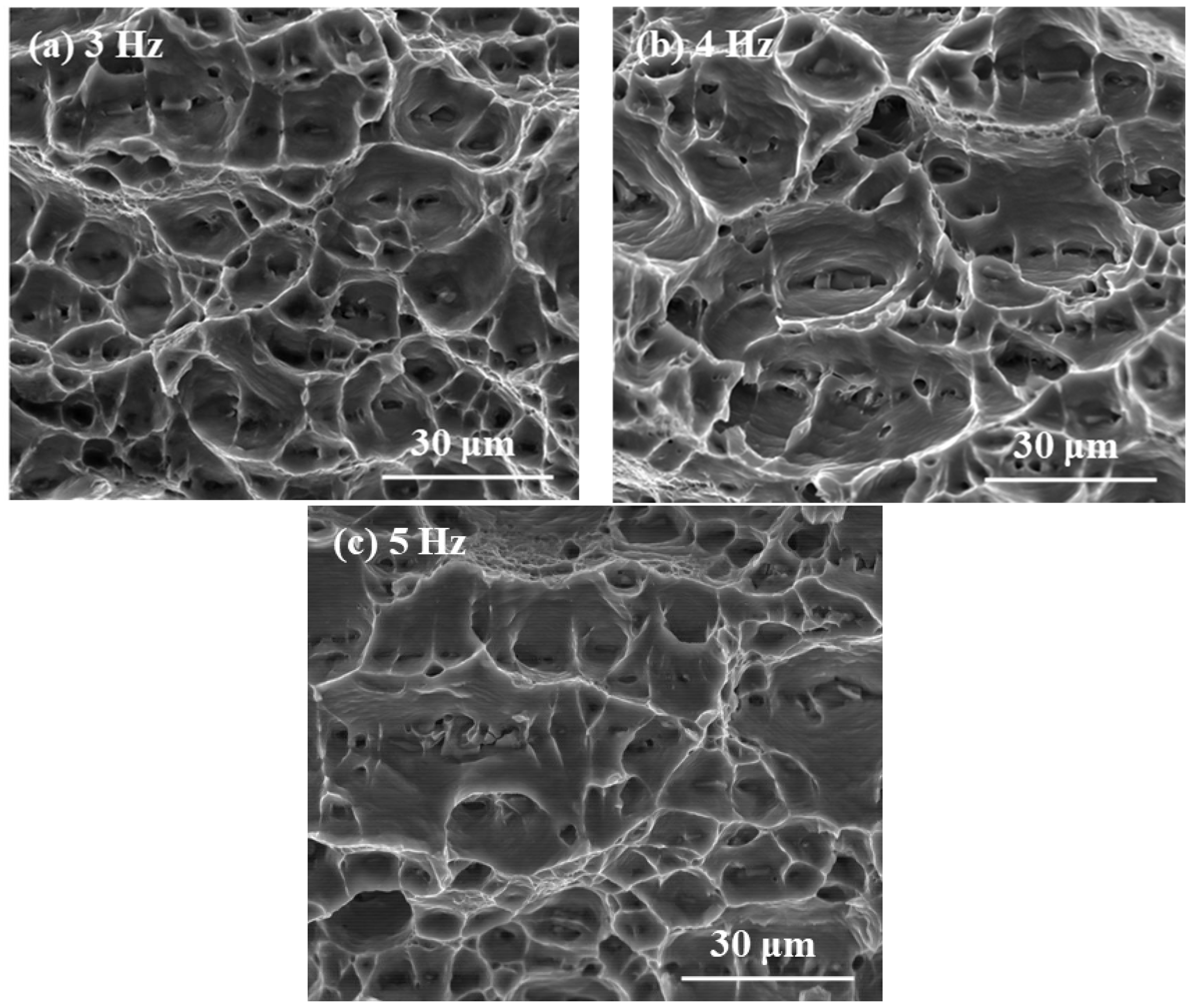
Figure 11 shows photographs of fractured tensile samples. When the thermal frequency is 3, 4, and 5 Hz, tensile fractures of the welded joint are mainly composed of a large number of irregular dimples. In the bottoms of the dimples, inclusions and second phase particles are observed, indicating that the specimens have obvious plastic deformation before fracturing, and that the fracture belongs to a ductile fracture mode.
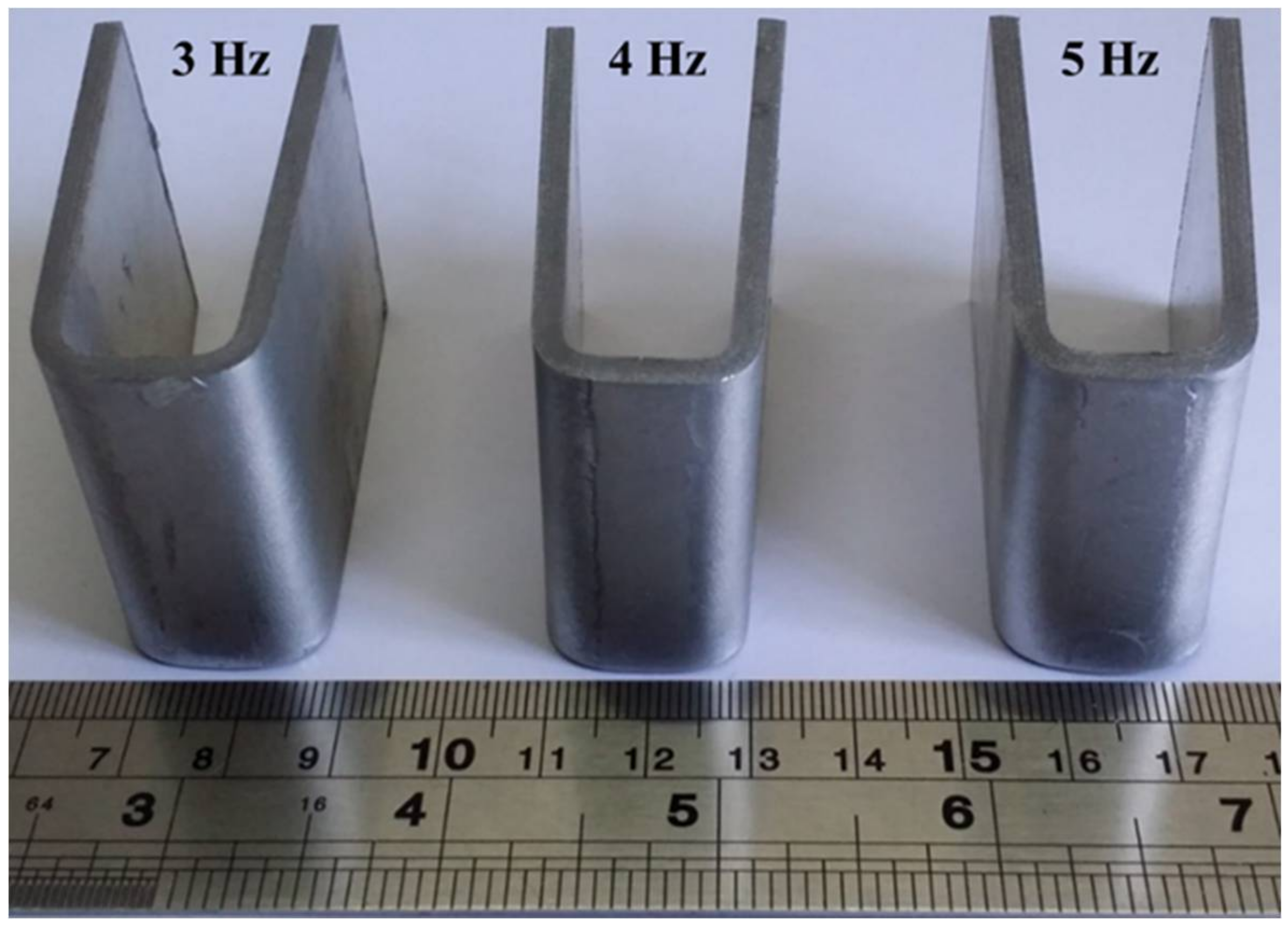
Three point bending test was adopted to the DP-GMAW welded samples to check the ductility of samples. The samples were carried out until 180°. A macroscopic photograph of the bended samples is shown in Figure 12. After bending up to 180°, no tearing, crack, and other defects are observed through a careful visual examination, which indicates the good ductility of the samples. As shown in Figure 7, the gain size of fusion zone is mostly concentrated in a small range from 20 μm to 50 μm, which may be the main reason for the excellent bending result.
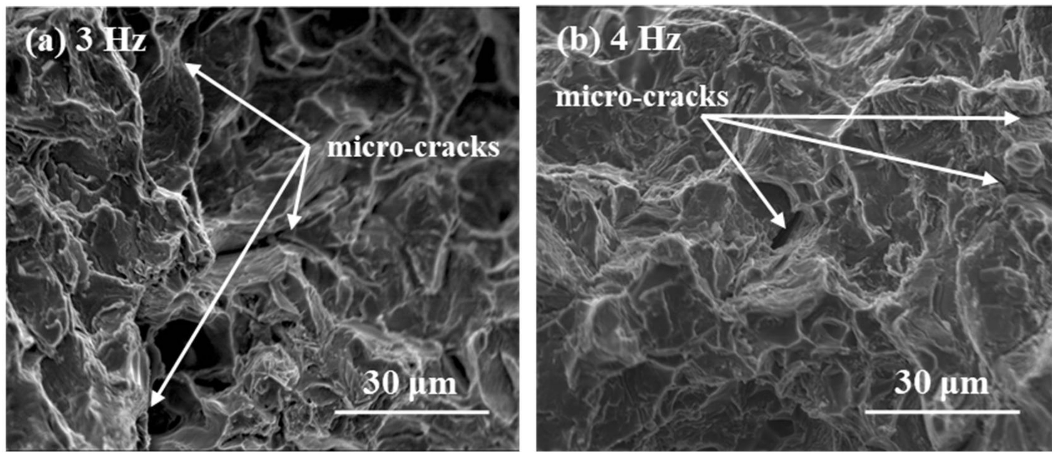
In this research, notches for the impact test of the welded joints were placed at the fusion zone and base metal, respectively. The impact properties of the base metal and the welded joint are shown in Table 4. It is observed that the absorbed energy of the base metal is 7.08 J, and that the absorbed energy of the welded joint is much lower than that of the base metal, which is about 30.8~31.9% of the latter. The SEM fractographs of Charpy impact test specimen are shown in Figure 13. It is observed that fractures surfaces of specimens have revealed cleavage facets, which indicates the occurrence of brittle fracture during the Charpy impact tests. Micro-cracks are exhibited in Figure 13, which may be the main reason for the low impact toughness of the welded 6061-T6 aluminum alloy.
3.6. Corrosion Properties
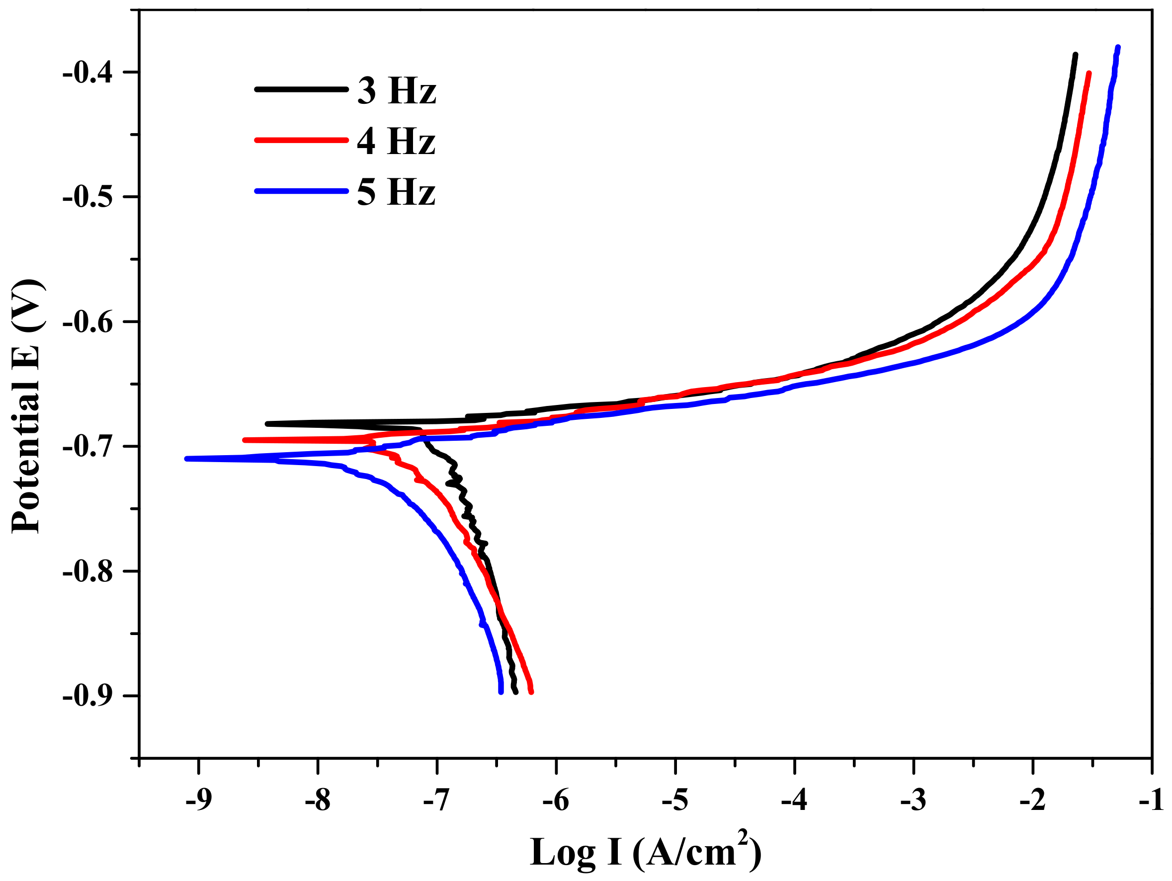
Figure 14 shows that the potentiodynamic polarization curves exhibit the pitting corrosion potential of welded joint produced using different thermal frequencies. It can be seen that increasing the thermal frequency from 3 Hz to 5 Hz shifts the corrosion potential from −667 to −715 mV, and decreases the corrosion potential from 2.39 × 10⁻⁷ to 4.47 × 10⁻⁸ A/cm2. According to the Figure 14, it is apparent that the corrosion properties of welded joint for 3, 4 Hz is less than that of the welded joint for 5 Hz. This might be due to the smaller grain size and the less porosity in the fusion zone, which is produced by higher thermal frequency. Maggiolino et al. [29] studied corrosion properties of aluminum alloy and reported that the porosity and crack would weaken the corrosion resistance of weld joint. The present result generally agrees with that work.
4. Conclusions
In the current research, 6061-T6 aluminum alloy workpieces were successfully butt welded at 3, 4, and 5 Hz by using the DP-GMAW. The microstructure evolution, mechanical, and corrosion properties of the weld joints were investigated. It is found that the thermal frequency of 5 Hz should be preferred when AA6061-T6 aluminum alloy is welded by DP-GMAW because of excellent microstructures, good mechanical and corrosion properties. The exhaustive main conclusions obtained from this investigation are as follows:
- (1)
- The welding processes using 3, 4, and 5 Hz are stable without spatter, and weld seams exhibits aesthetic ripples. The distance of adjacent ripples becomes wider, when the thermal frequency is lower.
- (2)
- The grain size and porosity of the fusion zone decrease with increasing thermal frequency, because the thermal frequency has an evident effect of improving the fluidity of the weld pool and inhibiting the growth of grains.
- (3)
- The Vickers microhardness of welded joint is higher, when the thermal frequency is higher.
- (4)
- When the thermal frequency changes from 3 Hz to 5 Hz, there is no significant difference in the tensile and impact result. The tensile and impact properties of welded joint are weaker than that of the base metal.
- (5)
- The samples welded at 3, 4, and 5 Hz can be bent to 180° and no separation, tearing, or crack is observed.
- (6)
- When the thermal frequency increases, the corrosion properties of welded joint also increase, due to the smaller grain size and less porosity in the fusion zone.
Acknowledgments
This work was supported by the High-level Leading Talent Introduction Program of GDAS (No. 2016GDASRC-0106), Industry-university- research of Guangdong province and Ministry of Education (No. 2013B090600098) and the National Natural Science Foundation of Guangdong Province (No. 2016A0303117).
Author Contributions
In this paper, Xue Jiaxiang gave the guidance and advice about how to analyze the result of the researches. Li Jin did the main job of this paper. Zhanhui Zhang and Yu Hu provided a lot of help for the experiment.
Conflicts of Interest
The authors declare no conflict of interest.
References
- Zhan, X.; Chen, J.; Liu, J.; Wei, Y.; Zhou, J.; Meng, Y. Microstructure and magnesium burning loss behavior of AA6061 electron beam welding joints. Mater. Des. 2016, 99, 449–458. [Google Scholar] [CrossRef]
- Springer, H.; Szczepaniak, A.; Raabe, D. On the role of zinc on the formation and growth of intermetallic phases during interdiffusion between steel and aluminium alloys. Acta Mater. 2015, 96, 203–211. [Google Scholar] [CrossRef]
- Madhavan, S.; Kamaraj, M.; Vijayaraghavan, L. Cold metal transfer welding of aluminium to magnesium: Microstructure and mechanical properties. Sci. Technol. Weld. Join. 2016, 21, 310–316. [Google Scholar] [CrossRef]
- Gungor, B.; Kaluc, E.; Aydin, S.I.K. Mechanical and microstructural properties of robotic Cold Metal Transfer (CMT) welded 5083-H111 and 6082-T651 aluminum alloys. Mater. Des. 2014, 54, 207–211. [Google Scholar] [CrossRef]
- Rodriguez, R.I.; Jordon, J.B.; Allison, P.G.; Rushing, T.; Garcia, L. Microstructure and mechanical properties of dissimilar friction stir welding of 6061-to-7050 aluminum alloys. Mater. Des. 2015, 83, 60–65. [Google Scholar] [CrossRef]
- Tan, Y.B.; Wang, X.M.; Ma, M.; Zhang, J.X.; Liu, W.C.; Fu, R.D.; Xia, S. A study on microstructure and mechanical properties of AA 3003 aluminum alloy joints by underwater friction stir welding. Mater. Charact. 2017, 127, 41–52. [Google Scholar] [CrossRef]
- Bunaziv, I.; Akselsen, O.M.; Salminen, A.; Unt, A. Fiber laser-MIG hybrid welding of 5 mm 5083 aluminum alloy. J. Mater. Process. Technol. 2016, 233, 107–114. [Google Scholar] [CrossRef]
- Aloraier, A.S.; Joshi, S.; Price, J.W.H.; Alawadhi, K. Hardness, microstructure, and residual stresses in low carbon steel welding with postweld heat treatment and temper bead welding. Metall. Mater. Trans. A 2014, 45, 2030–2037. [Google Scholar] [CrossRef]
- Liu, A.H.; Tang, X.H.; Lu, F.G. Weld pool profile characteristics of Al alloy in double-pulsed GMAW. Int. J. Adv. Manuf. Technol. 2013, 68, 2015–2023. [Google Scholar] [CrossRef]
- Yamamoto, H.; Harada, S.; Ueyama, T.; Ogawa, S. Development of low-frequency pulsed MIG welding for aluminium alloys. Weld. Int. 1992, 6, 580–583. [Google Scholar] [CrossRef]
- Yamamoto, H.; Harada, S.; Ueyama, T.; Ogawa, S.; Matsuda, F.; Nakata, K. Beneficial effects of low-frequency pulsed MIG welding on grain refinement of weld metal and improvement of solidification crack susceptibility of aluminium alloys: Study of low-frequency pulsed MIG welding. Weld. Int. 1993, 7, 456–461. [Google Scholar] [CrossRef]
- Liu, A.H.; Tang, X.H.; Lu, F.A. Study on welding process and prosperities of AA5754 Al-alloy welded by double pulsed gas metal arc welding formation in aluminum GMAW. Mater. Des. 2013, 50, 149–155. [Google Scholar] [CrossRef]
- Mendes da Silva, C.L.; Scotti, A. The influence of double pulse on porosity formation in aluminum GMAW. J. Mater. Process. Technol. 2006, 171, 366–372. [Google Scholar] [CrossRef]
- Liu, A.H.; Tang, X.H.; Lu, F.G. Arc profile characteristics of Al alloy in double-pulsed GMAW. Int. J. Adv. Manuf. Technol. 2013, 65, 1–7. [Google Scholar] [CrossRef]
- Pires, I.; Quintino, L.; Miranda, R.M. Analysis of the influence of shielding gas mixtures on the gas metal arc welding metal transfer modes and fume formation rate. Mater. Des. 2007, 28, 1623–1631. [Google Scholar] [CrossRef]
- Liu, C.; Liu, Z.; Ruan, X. Effect of post-weld heat treatment on microstructure and mechanical properties of welded joint of 7075 aluminum alloy by double-pulsed metal inert-gas welding process. Trans. China Weld. Inst. 2016, 37, 81–84. [Google Scholar]
- Yi, J.; Cao, S.; Li, L.; Guo, P.; Liu, K. Effect of welding current on morphology and microstructure of Al alloy T-joint in double-pulsed MIG welding. Trans. Nonferr. Metals Soc. China 2015, 25, 3204–3211. [Google Scholar] [CrossRef]
- Yao, P.; Xue, J.; Meng, W.; Zhu, S. Influence of processing parameters on weld forming in double-pulse MIG welding of aluminum alloy. Trans. China Weld. Inst. 2009, 30, 69–72. [Google Scholar]
- Mathivanan, A.; Devakumaran, K.; Kumar, A.S. Comparative study on mechanical and metallurgical properties of AA6061 aluminum alloy sheet weld by pulsed current and dual pulse gas metal arc welding processes. Mater. Manuf. Process. 2014, 29, 941–947. [Google Scholar] [CrossRef]
- Zhu, Q.; Xue, J.X.; Yao, P.; Dong, C.W.; Wang, L.L.; Heng, G.C.; Li, Z.H. Gaussian pulsed current waveform welding for aluminum alloys. Mater. Manuf. Process. 2015, 30, 1124–1130. [Google Scholar] [CrossRef]
- Li, J.X.; Li, H.; Wei, H.L.; Ni, Y.B. Effect of pulse on pulse frequency on welding process and welding quality of pulse on pulse MIG welding-brazing of aluminum alloys to stainless steel. Int. J. Adv. Manuf. Technol. 2016, 87, 51–63. [Google Scholar] [CrossRef]
- Pal, K.; Pal, S.K. Effect of pulse parameters on weld quality in pulsed gas metal arc welding: A review. J. Mater. Eng. Perform. 2011, 20, 918–931. [Google Scholar] [CrossRef]
- Pal, K.; Pal, S.K. Study of weld joint strength using sensor signals for various torch angles in pulsed MIG welding. J. Manuf. Sci. Technol. 2010, 3, 55–65. [Google Scholar] [CrossRef]
- Cho, M.H.; Farson, D.F. Understanding bead hump formation in gas metal arc welding using a numerical simulation. Metall. Meter. Trans. B 2007, 38, 305–319. [Google Scholar] [CrossRef]
- Goyal, V.; Ghosh, P.; Saini, J. Influence of pulse parameters on characteristics of bead-on-plate weld deposits of aluminum and its alloy in the pulsed gas metal arc welding process. Metall. Mater. Trans. A 2008, 39, 3260–3275. [Google Scholar] [CrossRef]
- Engler, O.; Hirsch, J. Texture control by thermomechanical processing of AA6xxx Al–Mg–Si sheet alloys for automotive applications—A review. Mater. Sci. Eng. A 2002, 336, 249–262. [Google Scholar] [CrossRef]
- Myhr, O.R.; Grong, Ø.; Pedersen, K.O. A combined precipitation, yield strength, and work hardening model for Al-Mg-Si alloys. Metall. Meter. Trans. A 2010, 41, 2276–2289. [Google Scholar] [CrossRef]
- Kumar, A.; Sundarrajan, S. Effect of welding parameters on mechanical properties and optimization of pulsed TIG welding of Al-Mg-Si alloy. Int. J. Adv. Manuf. Technol. 2009, 42, 118–125. [Google Scholar] [CrossRef]
- Maggiolino, S.; Schmid, C. Corrosion resistance in FSW and in MIG welding techniques of AA6XXX. J. Mater. Process. Technol. 2008, 197, 237–240. [Google Scholar] [CrossRef]
Figure 1.
The current waveform of double pulsed gas metal arc welding (DP-GMAW).

Figure 2.
The experimental setup of DP-GMAW.

Figure 3.
Dimensions of test specimens (unit: mm): (a) Tensile test specimen; (b) Charpy impact test specimen; and, (c) Bend test specimen.
Figure 3.
Dimensions of test specimens (unit: mm): (a) Tensile test specimen; (b) Charpy impact test specimen; and, (c) Bend test specimen.

Figure 4.
Transient electrical signal waveforms of DP-GMAW: (a) 3 Hz; (b) 4 Hz; and, (c) 5 Hz.

Figure 5.
Transient input energy and transient resistance waveforms of DP-GMAW: (a) 3 Hz; (b) 4 Hz; and, (c) 5 Hz.
Figure 5.
Transient input energy and transient resistance waveforms of DP-GMAW: (a) 3 Hz; (b) 4 Hz; and, (c) 5 Hz.

Figure 6.
Weld bead shape and porosity: (a) weld bead shape; and, (b) distribution of porosity on longitudinal section.
Figure 6.
Weld bead shape and porosity: (a) weld bead shape; and, (b) distribution of porosity on longitudinal section.

Figure 7.
Microstructure photograph of fusion zone.

Figure 8.
Energy dispersive spectrometer (EDS) maps of Magnesium elemental in fusion zone.

Figure 9.
Microhardness distribution in welded joints.

Figure 10.
Tensile properties of the base metal and welded joint. (a) Tensile curves; and, (b) Result of tensile tests.
Figure 10.
Tensile properties of the base metal and welded joint. (a) Tensile curves; and, (b) Result of tensile tests.


Figure 11.
Photographs of fractured tensile samples.

Figure 12.
Macroscopic pictures of the bended samples.

Figure 13.
Scanning electron microscope (SEM) fractographs of impact specimens.


Figure 14.
Potentiodynamic polarization curves of welded joint produced by different thermal frequency.
Figure 14.
Potentiodynamic polarization curves of welded joint produced by different thermal frequency.


Table 1.
The chemical compositions of base metal and filler wire (mass fraction, %).
| Element | Si | Fe | Cu | Mg | Cr | Zn | Ti | Al |
|---|---|---|---|---|---|---|---|---|
| AA6061-T6 | 0.52 | 0.25 | 0.012 | 0.96 | 0.26 | 0.021 | 0.012 | Bal. |
| ER4043 | 4.50-6.00 | 0.80 | 0.30 | 0.05 | -- | 0.01 | 0.20 | Bal. |
Table 2.
Main welding parameters of DP-GMAW.
| Parameters | Average Current (A) | Average Voltage (V) | Flow of Argon (L/min) | Welding Speed (cm/min) | Thermal Frequency (Hz) |
|---|---|---|---|---|---|
| Value | 100 | 20 | 16 | 50 | 3, 4, 5 |
Table 3.
Macrostructure details and porosity of weld beads.
| Thermal Frequency (Hz) | Weld Width (mm) | Weld Deep (mm) | Weld W/D Ratio | Porosity (N/mm) |
|---|---|---|---|---|
| 3 | 7.38 | 7.66 | 1.21 | 6 |
| 4 | 7.66 | 7.64 | 1.29 | 3 |
| 5 | 8.10 | 7.30 | 1.49 | 1 |
Table 4.
Impact properties of the base metal and welded joint.
| Thermal Frequency, (Hz) | Absorded Energy, Akv (J) | ||||
|---|---|---|---|---|---|
| 1 | 2 | 3 | Average Value | Standard Deviation | |
| Base Metal | 7.25 | 7.00 | 7.00 | 7.08 | 0.14 |
| 3 | 2.22 | 2.15 | 2.17 | 2.18 | 0.03 |
| 4 | 2.25 | 2.25 | 2.27 | 2.26 | 0.01 |
| 5 | 2.45 | 2.00 | 2.22 | 2.22 | 0.22 |
© 2018 by the authors. Licensee MDPI, Basel, Switzerland. This article is an open access article distributed under the terms and conditions of the Creative Commons Attribution (CC BY) license (http://creativecommons.org/licenses/by/4.0/).
Share and Cite
MDPI and ACS Style
Jin, L.; Xue, J.; Zhang, Z.; Hu, Y. Effects of Thermal Frequency on Microstructures, Mechanical and Corrosion Properties of AA6061 Joints. Appl. Sci. 2018, 8, 540. https://doi.org/10.3390/app8040540
AMA Style
Jin L, Xue J, Zhang Z, Hu Y. Effects of Thermal Frequency on Microstructures, Mechanical and Corrosion Properties of AA6061 Joints. Applied Sciences. 2018; 8(4):540. https://doi.org/10.3390/app8040540
Chicago/Turabian StyleJin, Li, Jiaxiang Xue, Zhanhui Zhang, and Yu Hu. 2018. "Effects of Thermal Frequency on Microstructures, Mechanical and Corrosion Properties of AA6061 Joints" Applied Sciences 8, no. 4: 540. https://doi.org/10.3390/app8040540
Note that from the first issue of 2016, this journal uses article numbers instead of page numbers. See further details here.