Application of Auxetic Foam in Sports Helmets
by
 , ,
, ,
Leon Foster
1,* ,
,
Prashanth Peketi
2,
Thomas Allen
3 ,
,
Terry Senior
1,
Olly Duncan
4 and
Andrew Alderson
4 1
Centre for Sports Engineering Research, Sheffield Hallam University, Sheffield S1 1WB, UK
2
Adidas Futures Team, Portland, OR 97217, USA
3
School of Engineering, Manchester Metropolitan University, Manchester M1 5GD, UK
4
Materials and Engineering Research Institute, Sheffield Hallam University, Sheffield S1 1WB, UK
*
Author to whom correspondence should be addressed.
Appl. Sci. 2018, 8(3), 354; https://doi.org/10.3390/app8030354
Submission received: 18 February 2018
/
Accepted: 19 February 2018
/
Published: 1 March 2018
(This article belongs to the Special Issue Sports Materials)
Abstract
:Featured Application
Auxetic open cell foam was used as the comfort layer within a sports helmet and has been shown to reduce the severity of linear impacts. The work undertaken highlights the potential to further develop auxetic open cell foam as comfort layer and create more effective sporting protective equipment to reduce transmitted linear as well as rotational accelerations during an impact.
Abstract
This investigation explored the viability of using open cell polyurethane auxetic foams to augment the conformable layer in a sports helmet and improve its linear impact acceleration attenuation. Foam types were compared by examining the impact severity on an instrumented anthropomorphic headform within a helmet consisting of three layers: a rigid shell, a stiff closed cell foam, and an open cell foam as a conformable layer. Auxetic and conventional foams were interchanged to act as the helmet’s conformable component. Attenuation of linear acceleration was examined by dropping the combined helmet and headform on the front and the side. The helmet with auxetic foam reduced peak linear accelerations (p < 0.05) relative to its conventional counterpart at the highest impact energy in both orientations. Gadd Severity Index reduced by 11% for frontal impacts (38.9 J) and 44% for side impacts (24.3 J). The conformable layer within a helmet can influence the overall impact attenuating properties. The helmet fitted with auxetic foam can attenuate impact severity more than when fitted with conventional foam, and warrants further investigation for its potential to reduce the risk of traumatic brain injuries in sport specific impacts.
1. Introduction
In the United States alone, sport accounts for an estimated 3.8 million traumatic brain injuries (TBIs) annually [1]. TBIs, which include mild traumatic brain injuries (mTBIs) such as concussions, occur frequently and are severely underreported [2]. Symptoms include headaches and fatigue, which can lead to an increased risk of clinical depression, decreased satisfaction with life, and increased levels of disability [3,4]. Sahler and Greenwald [1] state that preventative measures against TBI most commonly take two forms: rule changes and innovations in impact protection in the form of helmets. Rowson et al. [5] examined two American football helmet designs over the course of 1.28 million impacts in games and practice, and found that helmet choice could reduce the number of concussions athletes endure. The helmet modulates energy transferred to the head, and the amount of energy transferred can differ by design. Helmet and head injury studies tend to explore the helmets’ ability to reduce the risk of TBIs and mTBIs in sport [5,6,7].
Personal protective equipment (PPE), or other safety devices designed to prevent injuries arising from impact scenarios (short duration, high loading), aim to limit peak accelerations/forces, increase contact times, distribute loading, and perform energy attenuation. The performance of these safety devices is typically assessed by simulating an impact and measuring the ability to limit peak linear acceleration or force [8,9]. Helmet testing typically involves placing the helmet on the headform of an anthropomorphic test device (ATD) or a rigid headform, and using a drop-rig to transfer a known amount of impact energy. Accelerometers within the headform are used to record temporal accelerations and obtain impact characteristics including peak acceleration and impact duration [9,10]. Injury risk is typically quantified by assessing linear acceleration in combination with impact time, and relating to a severity index, such as the Head Impact Criterion (HIC) [11] and the Gadd Severity Index (GSI) [12]. GSI has been adopted in the protective equipment testing standards of the National Operating Committee on Standards for Athletic Equipment (NOCSAE) in the United States [10]. The GSI index is defined in Equation (1),
where A is the instantaneous resultant acceleration expressed as a multiple of gravity (g), dt is the time increment in seconds, and the integration bounds are from t0 to tf, the impact duration (determined by threshold value >0 g) [10,11]. New helmets are subjected to 16 impacts (44 to 60 J) onto a fixed rigid surface in six orientations. To pass the NOCSAE criterion, the GSI value for each impact must be below 1200, which signifies a non-injurious impact.
Helmets are a form of PPE used to protect the head and brain from injury. Impacts that contribute to head injury typically cause linear and rotational accelerations. The emphasis of attenuating rotational acceleration caused by oblique impacts has recently increased [13,14]. Oblique impacts increase the likelihood of brain injury [15] through mechanisms including: (i) rupturing arteries and bridging veins (causing subdural hematomas, SDH); and (ii) tearing neuro-connective tissue (causing diffuse axonal injuries, DAI) [16,17]. Mixed impacts (including rotational and linear accelerations) further increase the likelihood of fatal or coma inducing DAI and SDH [18,19,20]. Neither HIC nor GSI assess oblique or mixed impact testing, nor do they measure rotational acceleration, and historically helmet standards have been based on these indices [13,14]. Emphasis on linear (rather than rotational) acceleration has led to criticism of certifications and helmets alike [1].
To best attenuate linear acceleration, helmet materials are often viscoelastic, such as plastic based foams [21]. Compliant conformable foam is typically closest to the head (which is currently believed not to contribute to helmet function [22]), with stiffer, denser foam lining a hard-plastic shell [23]. A slip plane between a helmet’s shell and deformable layer aims to reduce rotational acceleration and is now included in many cycling and snowsports helmets [24]. Evidence supporting slip plane technology’s ability to reduce the likelihood of concussion is based on computational models, which have been criticized for not including physical validation [25,26,27]. A similar concept, increasing rotational deformation by reducing shear modulus, has reduced the severity of oblique impacts [22].
Despite helmet developments, there is evidence to suggest that the number of sport induced head injuries has not decreased. Firstly, Casson et al. [28] compared the number of concussed players in the National Football League (NFL) from the 1996–2001 and the 2002–2007 seasons. Suggested reasons for this lack of improvement in concussion rates are inadequate helmet design and certification. As recently as 2017, similar studies in snowsports saw helmet use rise dramatically after multiple high-profile deaths, serious injuries, and awareness campaigns, but with relatively little decrease in head injury rates [29,30].
Auxetic foams (with a negative Poisson’s ratio) have shown higher energy absorption than their conventional counterparts [31,32,33], and can be tailored to test the effect of mechanical characteristics (i.e., Young’s modulus and Poisson’s ratio) in complex situations (i.e., impact tests) [34,35]. Lakes originally fabricated auxetic foams through a compression and heat treatment process [36]. Conventional open cell foams were compressed triaxially, to produce a re-entrant cellular structure, in molds with a volumetric compression ratio (VCR) between 1.4 amd 4 (VCR = initial volume/final volume). The molds were heated (163–171 °C) to soften the foam, and then cooled to room temperature to set the re-entrant cellular structure. Auxetic foams fabricated in this way typically have: (i) higher density due to volumetric compression; and (ii) quasi-linear compressive stress/strain relationship rather than cellular collapse beyond ~5% compression typical in conventional open cell foams [37].
Auxetic conversion methods have developed, including suggestions of multiple heating cycles [38], mold lubrication [39], cooling the foam slowly within the mold [40], and passing pins through the foam to control compression [41,42]. Pins allowed lateral stretching but through thickness compression, producing auxetic foams with comparable density and compressive stress strain relationships to their unconverted counterpart [34,43].
Open cell auxetic foams exhibit peak forces ~3 to ~8 times lower than their unconverted counterparts when impacted in scenarios similar to sporting standards [31,32,38,43,44]. Previous work has impact tested foams in isolation [33,44,45] or covered with thin polypropylene shells [31,32,38,43,44]. Comparisons between auxetic and conventional foams have not been made in more complex multi-material systems, such as helmets. Closed cell foams with low magnitude, incremental negative Poisson’s ratio have been fabricated [46], but cells are reported to rupture during heat and compression. Therefore, the stability and practical benefits of closed cell auxetic foam is still in question and at present there are no studies that include impact testing of this type of foam (either as part of a complex system or in isolation).
This preliminary investigation aims to determine the effect on GSI when replacing an open cell conformable foam layer with an auxetic foam. Recent work assumes that the ‘comfort layer’ does not contribute to reduce impact severity [22]. Thermo-mechanically treating open cell foam alters its characteristics changing stress strain relationship, density, and Poisson’s ratio. This work will explore if changes to the comfort layer can affect impact severity on a headform within a test helmet.
2. Materials and Methods
The effect of using auxetic foam within a typical sports safety helmet was investigated through fabrication, characterization, and comparison of conventional and auxetic foams within a helmet. The original helmet (Coolflo Batting Helmet, Rawlings, St. Louis, MO, USA) contained three layers: (1) an open cell polyurethane foam as a conformable layer acting as an interface between the head and the helmet; (2) a closed cell ethylene-vinyl acetate (EVA) foam; and (3) a semi-rigid plastic exterior. This helmet was chosen for its simple construction which allowed easy substitution of candidate foams to act as the conformable layer.
The exact grade of open cell polyurethane foam used as the native conformable foam layer in the helmet was unknown and it was not possible to source additional foam of this grade for auxetic conversions. The conformable layer was therefore replaced with an alternative foam (PUR30FR, Custom Foams) which is well established for auxetic research, to ensure consistent conversion in line with previous studies [34,38,44]. A sample of the native conformable foam and the un-converted PU R30FR foam (41 × 127 × 25 mm) was compression tested through thickness (25 mm dimension) with a uni-axial test device (Instron 3367, Norwood, MA, USA, with a 500 N load cell) to 50% compression (0.0083 s−1). A linear trend line was fitted to the initial linear region of the stress vs. strain data to obtain Young’s modulus (34.3 kPa, plateau at 3–3.5 kPa, ~10% strain) and check it was comparable to PU R30FR (~30 kPa, plateau at 3–3.5 kPa, ~5 to 10% strain).
The auxetic foam was fabricated using a thermo-mechanical method for uniform sheets (~350 × 350 × 20 mm) with compression controlled by pins in the initial heating cycle, previously developed, and described in detail [34,42]. The same foam (PUR30FR, Custom Foams), mold compression regimes (isotropic Linear Compression Ratio, LCR of 0.7, defined as the ratio of the compressed to initial dimension), and heat cycles (25 min then 15 min at 180 °C) were employed. The annealing cycle was reduced to 10 min at 100 °C. Two foam sheets were produced, the first used for establishing the setup and pilot testing, and the second for final testing, to limit degradation.
Prior to impact testing within the helmet, the converted foam was characterized in order to ensure auxetic characteristics similar to previously created samples [34]. A 200 × 20 × 20 mm auxetic sample cut from the center of the pilot sheet was subjected to a quasi-static tensile test (Instron 3369, Norwood, MA, USA, 10 kN load cell) up to 50% extension (0.0017 s−1). The sample was held in place with bonded card-board end tabs (Araldite, Super Strength). Four white pins were placed in a square (10 mm sides) on the front face of the sample, and their movement during testing was recorded using an HD camcorder (JVC Everio, 1920 × 1080 pixels). Lateral vs. axial strain data (Marker Tracking, MATLAB, Mathworks 2015b [44]) were fitted with linear trend lines (between 0 and 50% extension) to obtain Poisson’s ratio.
Images of the foams and helmet can be seen in Figure 1 and the foam layer makeup is shown in Figure 2. Test foams were cut from the sheets in specific shapes using a bandsaw (Bauer Machinenbau). The forehead (Figure 1b) and side (Figure 1a,c) conformable foams were replaced with test foams. The top foam was only ~5 mm thick, and assumed to contribute less than other areas, to the helmet’s ability to reduce impact induced acceleration. Therefore, the native foam at the top location was left in situ. Velcro strip tape was used to hold foam samples in place, for ease of attachment and removal. Locating marks were placed on the ATD headform to ensure consistency of helmet placement for each test. The properties of both helmets are tabulated in Table 1, along with the specification of the foams used in testing. Note that there is a larger area and hence volume of foam used in the side inserts when compared to the front inserts.
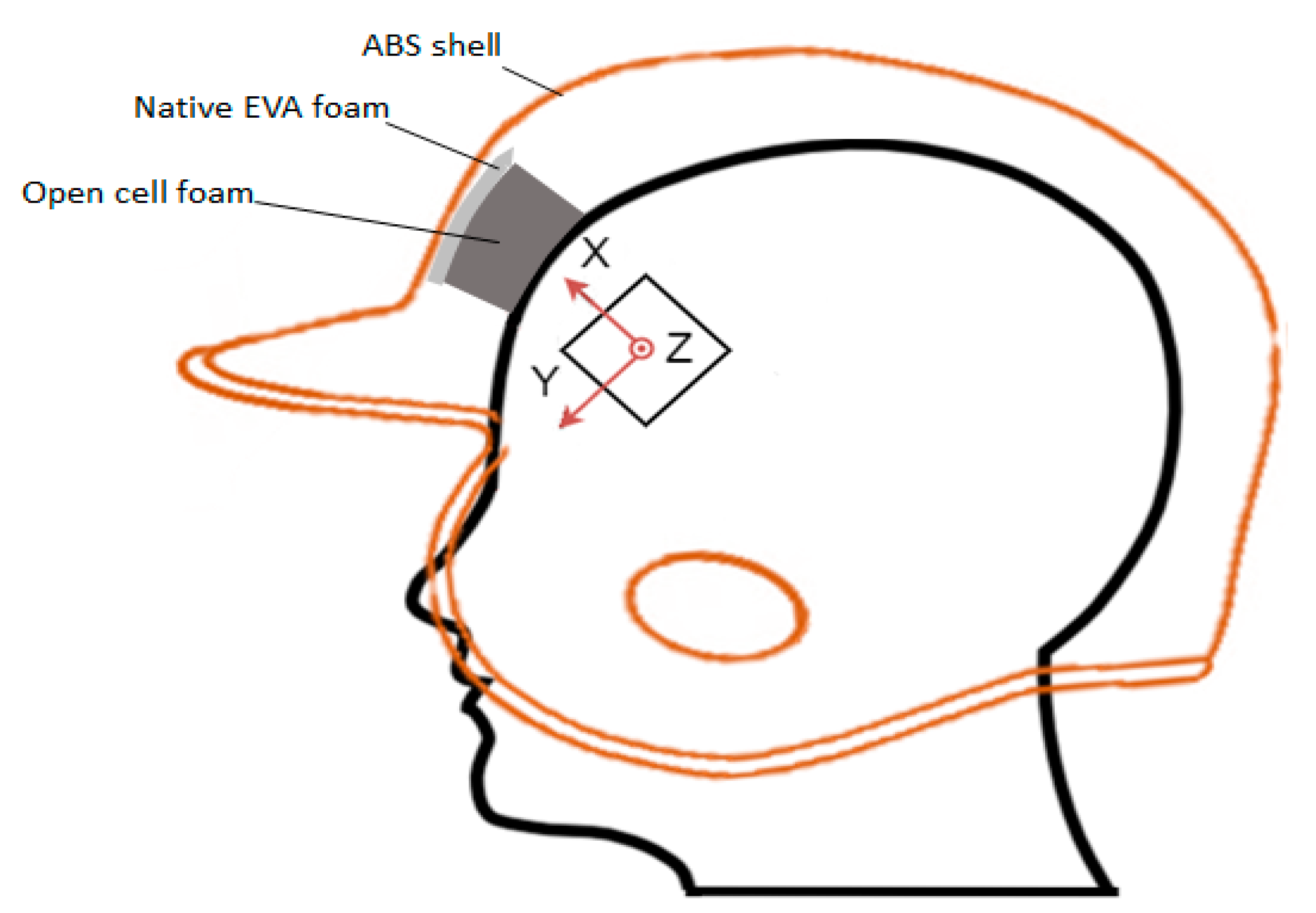
An Anthropomorphic Test Device (ATD) headform (Hybrid III 50th Percentile Male, Humanetics) provided a surrogate head inside the helmet. To measure acceleration, a ±200 g triaxial accelerometer, fixed to an evaluation board (ADXL377, Analog Devices) was mounted within the headform, Figure 2. The accelerometer was wired to an NI USB-6210 Data Acquisition Device (National Instruments, Austin, TX, USA), sampling at 41,666 Hz. The accelerometer setup was calibrated using the protocols in the Federal Motor Vehicle Safety Standard 572 No. 208-E [47].
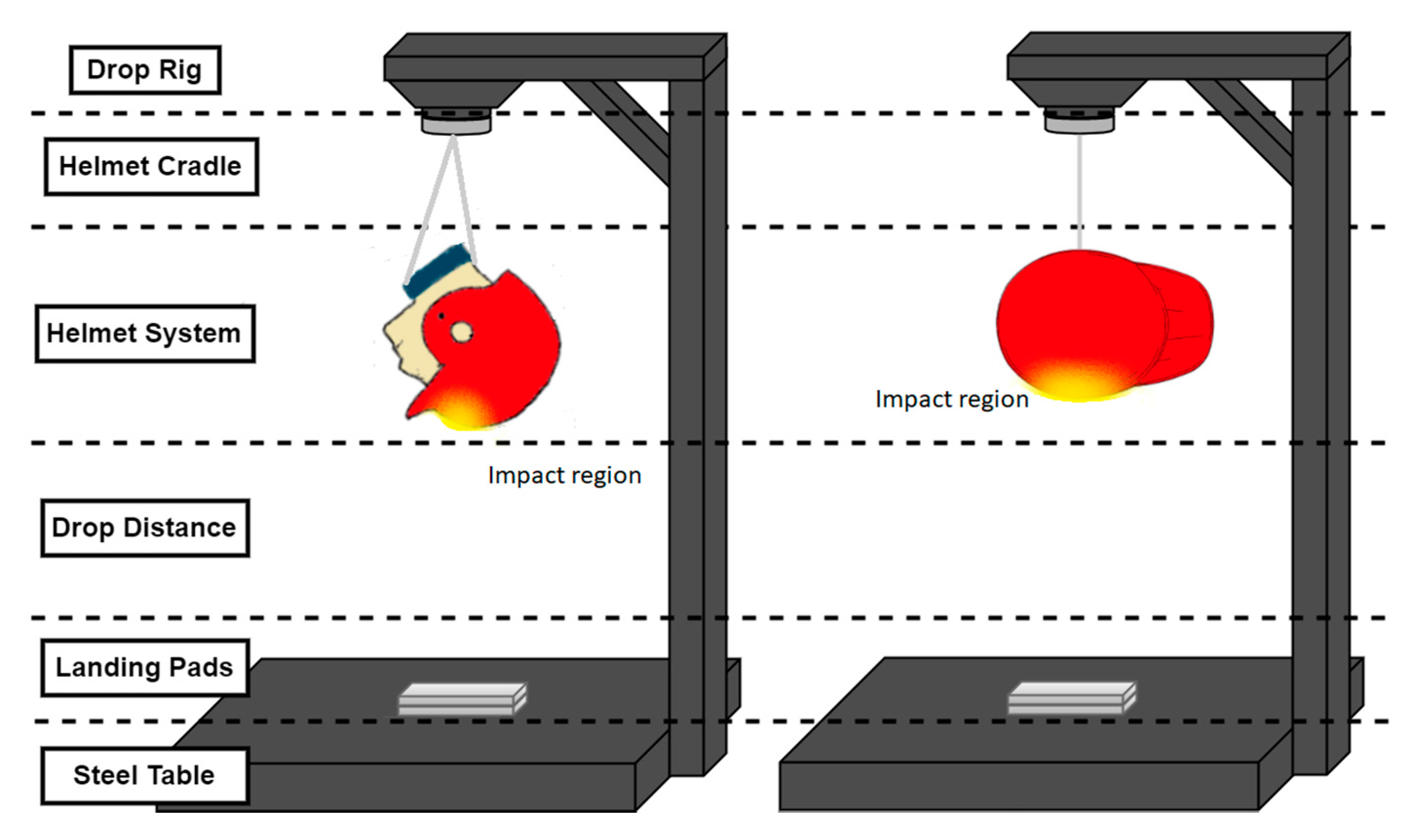
Testing was undertaken using a drop rig (Figure 3) with the helmet/headform in two orientations. Impact testing at multiple locations is typical of helmet test standards [10] and in this case was used to examine the severity of impact from a frontal and a side impact. The frontal and side impact tests engaged the forehead and side foams during the impact respectively.
Figure 3 shows both the frontal and side impact orientations, with the helmet landing on two thin (3 mm) polyurethane sheets, as used in the NOCSAE 001-13m15 standard [10]. These polyurethane sheets are used to prevent surface damage to the helmet. A range of drop heights (17, 25, 30, 37.6, 43, 50, 60, 70, and 80 cm) were tested, spanning impact energies of 8.3 to 38.9 J. These impact energies are below the 45 J maximum specified in the NOCSAE 022-10m12 [48] standard for the performance of baseball helmets (test helmet conforms to NOCSAE baseball standard). Impact energies were calculated based on the potential energy of the helmet/headform (mass ~5 kg). Five drop tests were completed at each drop height, for each foam type. The Gadd Severity Index was calculated for each impact. For frontal impacts, drop heights corresponding to impact energies of 8.3, 12.2, 14.6, 18.3, 20.9, 24.3, 29.2, 34.1, and 38.9 J were used. Side impacts were carried out at 12.2, 18.3, 20.9, and 24.3 J. The measuring range of the accelerometer in the z-axis prevented higher energy testing for the side impacts.
Steps were taken to ensure consistency of helmet positioning on the ATD, orientation of the magnetic drop cradle, location of landing pads, and drop height. String was wrapped through an existing hole in the helmet, and under the chin of the headform, to secure it to the headform and ensure that the helmet did not slide loose from the headform mid-trial. To limit any effect of foam degradation, each sample was removed from the helmet and allowed to recover for 10 min before the subsequent drop. Resting time was calculated based on pilot testing with samples from the first converted foam sheet. Drops over a range of energies (14.6–29.2 J) were completed with increasing rest times for the auxetic and conventional foam helmets, until five sequential readings of similar ‘peak’ accelerations (±5%) were measured. Tests were carried at room temperature, and environmental effects such as humidity and temperature were limited by alternately testing each foam in the helmet (after five repeats at each drop height) during the same period.
Raw acceleration data was logged for each test and post-processed. To minimize any systematic noise within the signal a fast Fourier transform (FFT) was applied to the raw acceleration data. Prominent noise frequencies were then removed using a notch filter. The impact duration of a drop test was distinguished by the period of time the acceleration rose above a baseline of 1.5 g. The Gadd Severity Index for each impact was then calculated using Equation (1) [12].
3. Results
The fabricated auxetic foam was found to have a marginally negative tensile Poisson’s ratio of −0.02, a Young’s Modulus of 34 kPa, and density of 83 kg/m3 which is comparable to previous work [34,38,44].
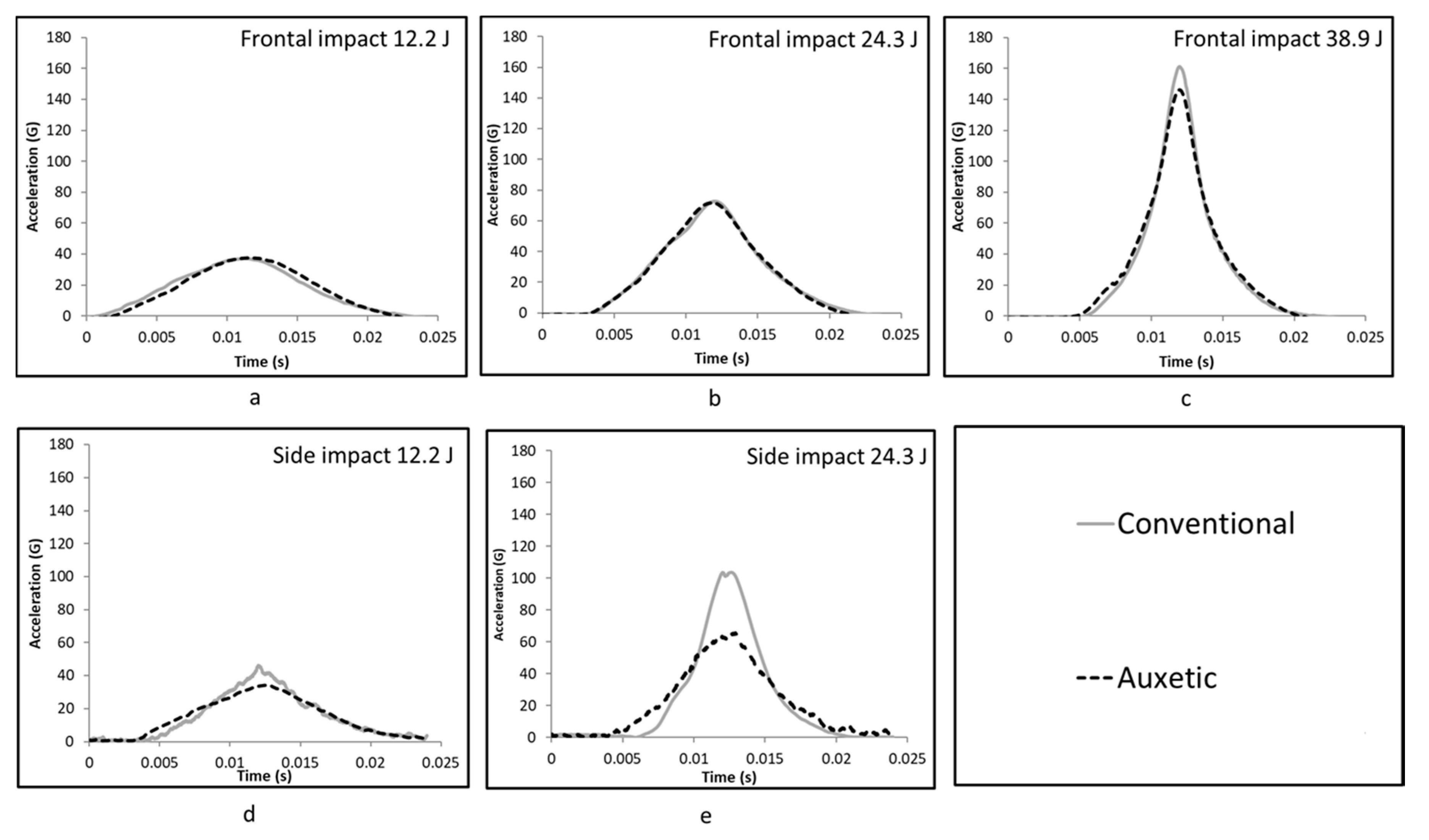
Resultant acceleration traces for frontal impacts with the conventional and auxetic foam inserts at low (12.3 J), medium (24.5 J), and high (38.9 J) energies are shown in Figure 4a–c. As expected, peak acceleration experienced by the headform increased with impact energy, and impact duration decreased. Figure 4d,e shows the resultant acceleration trace for side impacts. Conventional and auxetic foams perform in a similar fashion at low impact energies, but their performance appears to deviate at higher impact energy (29.2, 34.1, and 38.9 J). During a frontal impact at 38.9 J (Figure 4c) and side impact at 24.3 J (Figure 4e) auxetic foam inserts reduced the peak acceleration experienced by the headform. The mean Gadd Severity Index and standard deviation for each impact energy and foam inserts type has been summarized in Figure 5. Reflecting the acceleration traces in Figure 4, Gadd Severity Index increases with impact energy.
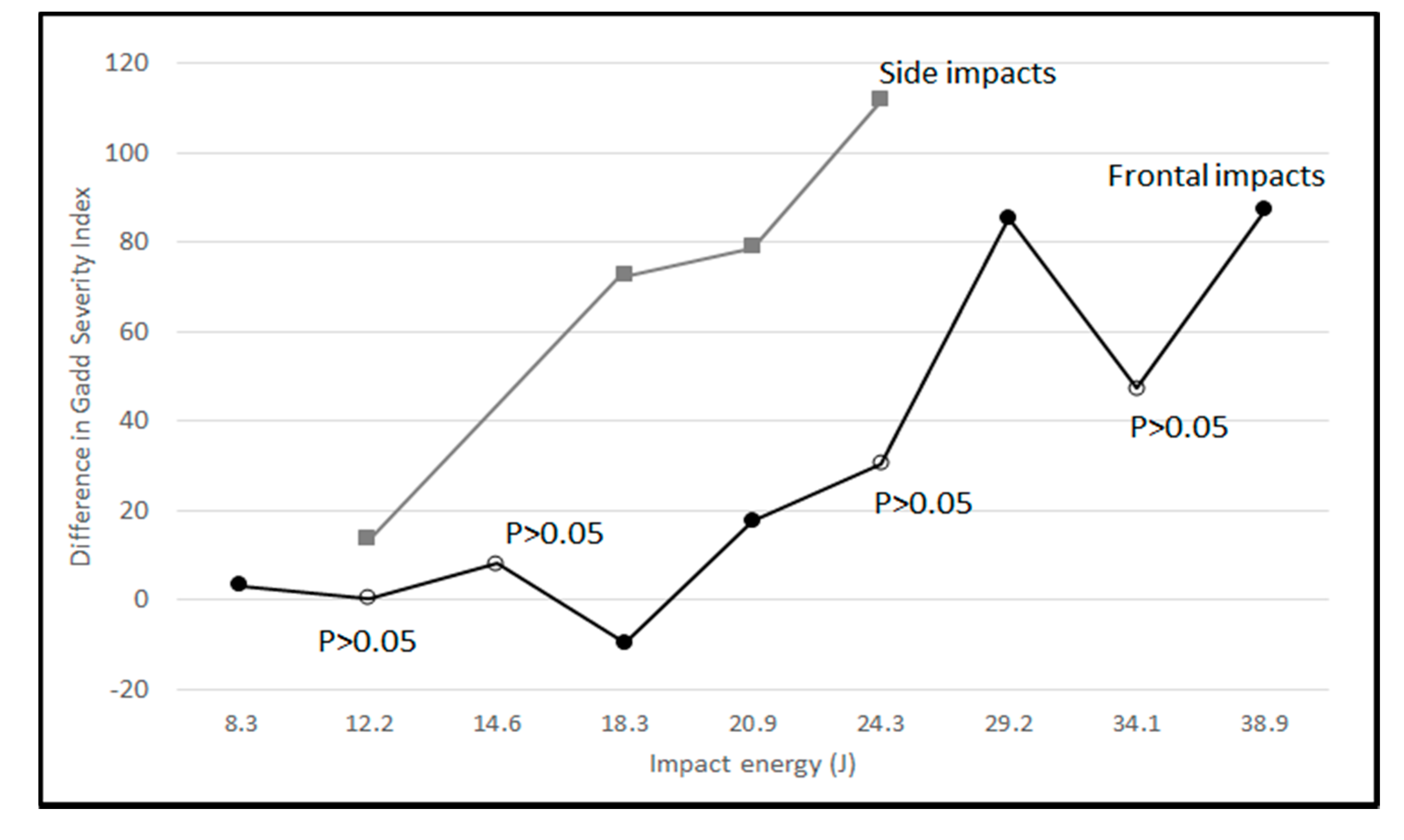
The difference in Gadd Severity Index between conventional foam inserts and auxetic foam inserts for each impact energy is shown in Figure 6. The greater the positive value, the more the auxetic foam inserts reduces the GSI and a negative value indicates that the conventional foam inserts perform better. The general trend indicates the difference between foam types increases with impact energy. Note that the open markers in Figure 6 show where the difference was not significant based on an unpaired t-test (p > 0.05).
A factorial analysis of variance (FANOVA) was carried out for the data collected in (1) the frontal drop test and (2) the side drop test. In both cases, it was found that there was a significant effect for the impact energy, foam insert type, and also an interaction effect (p < 0.05 in all cases). This p-value of less than 0.05 indicates that the performance of the different foam insert varies depending on impact energy, and referring back to Figure 6, it appears that this interaction effect means that at lower impact energies, the performance of each foam type is similar but at higher impact energies they differentiate.
4. Discussion
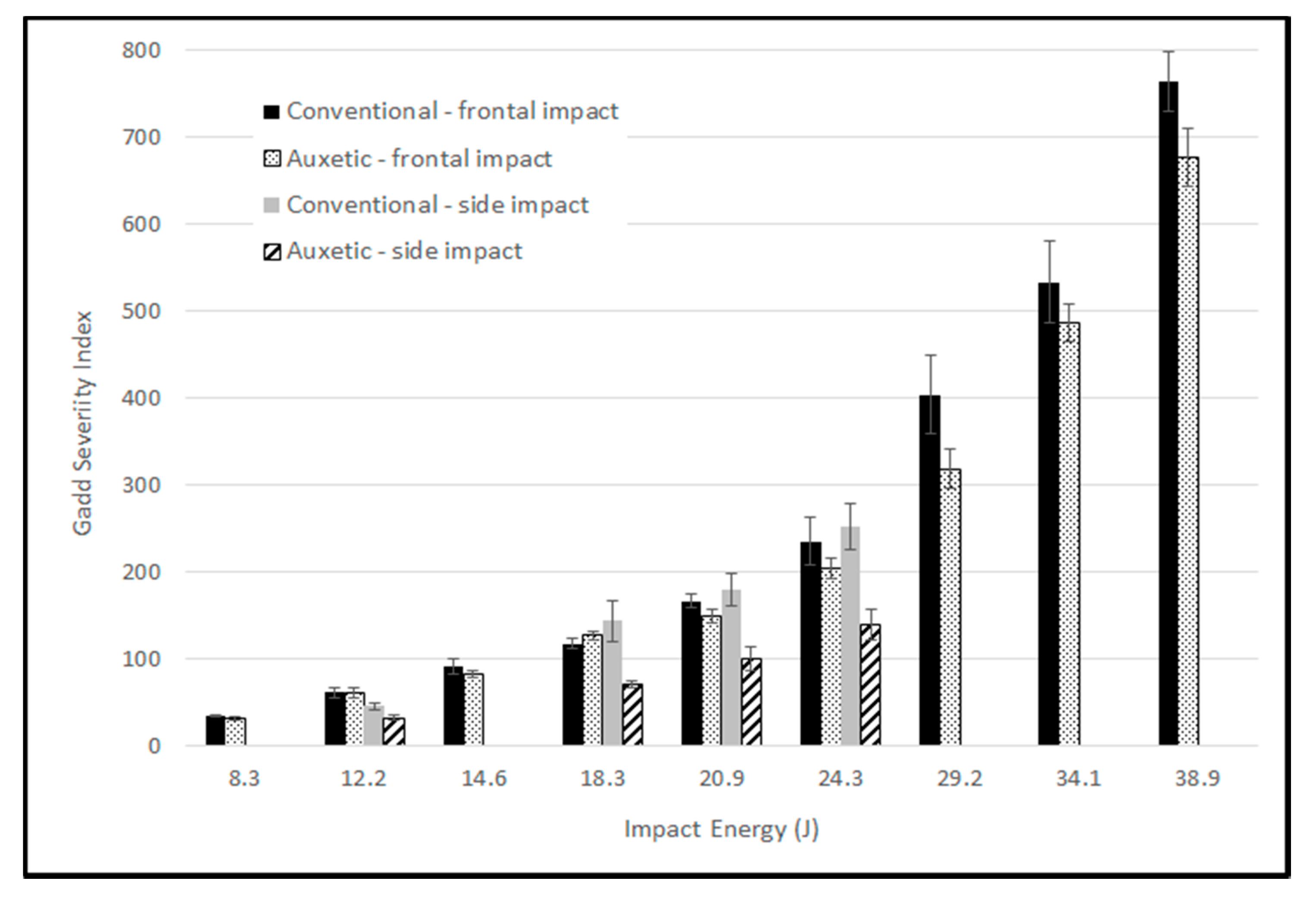
A helmet with auxetic foam inserts significantly (p < 0.05) reduced the acceleration recorded by the headform accelerometer at the highest impact energy in both frontal and side impacts. In the frontal drop test at an impact energy of 38.9 J the auxetic foam reduced the GSI by 11.4%. In the side drop test at an impact energy of 24.3 J the difference in GSI was 44.2% between the foam types. At lower impact energies it appears that the difference between foam types is less, and only when the impact energy was above 18.3 J for the frontal drops did the auxetic foam reduce the GSI in comparison to conventional foam. For side drops at all impact energies tested, the auxetic foam performed better, reducing all GSI values. For the frontal drop test at the second highest impact energy (34.1 J), the auxetic foam inserts did seem to perform better than the conventional counterpart but this difference was not deemed significant at the 95% confidence level. The reason for this difference not being significant at 34.1 J is likely due to measurements errors, although there could be an underlying interaction effect of the foams, helmet, and headform at this impact energy which renders the auxetic foam less effective. In-depth further investigation, with more samples and tests scenarios, is required to fully understand the effectiveness of auxetic foams in comparison to their conventional counterpart across a range of impact energies.
In general, the findings are in line with previous work where auxetic foam tested in isolation or with thin polypropylene sheets attenuated linear impact acceleration to a greater extent at higher impact energies [34,38,44]. Allen et al. [38] stated that this behavior could be attributed to the auxetic foam’s resistance to “bottoming out” during impact. ‘Bottoming out’ is the point at which an impact attenuating system becomes saturated due to high loading and the effectiveness of the system diminishes significantly. In the case of Allen et al. [38], this would be when the foam compresses to such an extent that it was no longer effective, and the impactor is essentially striking the anvil. At this point, the acceleration trace will show a ‘spike’ (short duration high peak).
In this study, any ‘bottoming out’ of the helmet system is hard to identify and assess due to the multi-layered foam construction of the helmet. The ‘bottoming out’ of the conventional open cell foam is likely to occur when the performance of the auxetic and conventional foam diverges. For the frontal impacts, deviation in impact severities occurs at an impact energy around 20.9 J, but for the side impacts this occurs at the lowest energy tested at 12.2 J. The reason why a conventional foam ‘bottoms out’ when compared to an auxetic foam is still unknown but could be due to the auxetic foams’ deformation process and densification of the material occurring under the impact location [38].
Figure 6 illustrates that during the side impact tests the auxetic foam system appeared to produce significantly lower severity index over the range of energies tested. This significant improvement in the auxetic foam during the side drop test could be explained by the variation in the amount of foam within the helmet. The side conformable foam insert had approximately twice the amount of foam when compared to the front insert (Table 1). Therefore, during the side drop tests the increased amount of foam in the side insert appeared to exaggerate the energy attenuation ability of the auxetic foam. The conventional foam in the side impact test performed in a similar manner to the frontal drop test with similar GSI values. It appears that as the surface area and hence volume of the foam increases this also increases the ability of the auxetic foam to reduce GSI. However, the relationship between the auxetic foam’s area/volume and its energy attenuating ability is unclear. The exact mechanism for why a larger amount of auxetic foam enhances its performance warrants further investigation but could be related to either the density of the auxetic foam, the curvature of the impacting objects, or the ability of the auxetic foam to densify under impact more effectively in a larger volume.
The thickness of the closed cell layer of native foam also varied within the helmet and was thicker in the front when compared to the side (~6 mm and ~4 mm respectively, Table 1). This means the contribution of the conformable layer during an impact may have been reduced at the front location. In general, the auxetic foam appeared to outperform or be equivalent to the conventional foam for both impact orientations.
Previous work [34,38,44] found much larger acceleration attenuation differences between the auxetic and conventional foams, on the scale of 300–800% compared to a maximum of 44% in this study. However, this reduction in the effectiveness of auxetic foams may be expected as they are no longer being tested in isolation, but as part of a multi-layered helmet. Findings agree with previous work [33,36], and it is notable that the conformable layer can significantly affect the helmet’s performance. As the comfort layer can influence impact properties, the use of tuned auxetic foams could be used to enhance a helmet’s performance. However, the effect of modifying the open cell layer within a helmet on the additional functions (i.e., fit and comfort) are yet to be assessed.
Anisotropic foams with low shear modulus could be used in helmets to specifically reduce rotational accelerations. Anisotropy and uniaxial Poisson’s ratios can be increased in open cell foams by stretching parallel to cell rise during fabrication [34,35,49] rather than compressing (which typically reduces anisotropy and Poisson’s ratio) [36]. Given that the open cell layer can reduce impact severity. Further work should expand upon reduced rotational accelerations exhibited by anisotropic foams with a low shear modulus and could be a way of reducing rotational acceleration in certain impacts, either as an alternative to or in parallel with slip plane technology [22,24]. One emerging area requiring further investigation is the use of 3D printed foams/structures which could enhance and tailor the impact performance of helmets further still [50]. This study is limited to one helmet design at two impacting sites using one grade of conventional and auxetic foam. Further work is required to replicate this experiment for a range of different helmets, foam grades, and impact scenarios across a number of sports. It would also be necessary to investigate how the tailoring of helmet liners influences ergonomic considerations, including pressure distribution, comfort, and fit.
5. Conclusions
This investigation revealed important advantages of the helmet containing auxetic foam to its conventional counterpart. The auxetic foam helmet attenuated linear acceleration significantly more than the conventional foam helmet for frontal impacts at the highest impact energy tested and for side impacts at all energies tested. The conventional foam in side impact tests appeared to perform in a similar manner to frontal drop tests at all energies, but auxetic foam in side impact tests produced significantly lower severity indices. Ultimately, this finding supports previous research indicating that auxetic foams could be utilized in sports safety applications and could lead into an interesting study to assess whether tailoring the open cell conformable layer in a traditional helmet by varying Poisson’s ratio could reduce the risk of sport induced TBIs.
Author Contributions
Leon Foster, Thomas Allen, Andy Alderson, Terry Senior, and Prashanth Peketi conceived and designed the experiments, with Terry Senior designing and manufacturing all components required for drop testing. Prashanth Peketi carried out the experiment, wrote up the results, and analyzed the data. Leon Foster, Olly Duncan, and Prashanth Peketi wrote the paper which was edited by Thomas Allen and Andrew Alderson.
Conflicts of Interest
The authors declare no conflict of interest.
References
- Sahler, C.S.; Greenwald, B.D. Traumatic brain injury in sports: A review. Rehabil. Res. Pract. 2012, 2012, 659652. [Google Scholar] [CrossRef] [PubMed]
- McCrea, M.; Hammeke, T.; Olsen, G.; Leo, P.; Guskiewicz, K. Unreported concussion in high school football players: Implications for prevention. Clin. J. Sport Med. 2004, 14, 13–17. [Google Scholar] [CrossRef] [PubMed]
- Stålnacke, B.; Björnstig, U.; Karlsson, K.; Sojka, P. One-year follow-up of patients with mild traumatic brain injury: Post-concussion symptoms, disabilities and life satisfaction at follow-up in relation to serum levels of S-100B and neuron-specific enolase in acute phase. J. Rehabil. Med. 2005, 37, 300–305. [Google Scholar] [CrossRef] [PubMed]
- Guskiewicz, K.M.; Marshall, S.W.; Bailes, J.; McCrea, M.; Harding, H.P., Jr.; Matthews, A.; Mihalik, J.R.; Cantu, R.C. Recurrent concussion and risk of depression in retired professional football players. Med. Sci. Sports Exerc. 2007, 39, 903–909. [Google Scholar] [CrossRef] [PubMed]
- Rowson, S.; Duma, S.M.; Greenwald, R.M.; Beckwith, J.G.; Chu, J.J.; Guskiewicz, K.M.; Mihalik, J.P.; Crisco, J.J.; Wilcox, B.J.; McAllister, T.W.; et al. Can helmet design reduce the risk of concussion in football? Technical note. J. Neurosurg. 2014, 120, 919–922. [Google Scholar] [CrossRef] [PubMed]
- Kis, M.; Saunders, F.; ten Hove, M.; Leslie, J. Rotational acceleration measurements-evaluating helmet protection. Can. J. Neurol. Sci. 2004, 31, 499–503. [Google Scholar] [CrossRef] [PubMed]
- Post, A.; Hoshizaki, T.B. Rotational acceleration, brain tissue strain, and the relationship to concussion. J. Biomech. Eng. 2015, 137, 030801. [Google Scholar] [CrossRef] [PubMed]
- Rowson, S.; Duma, S.M. Development of the STAR evaluation system for football helmets: Integrating player head impact exposure and risk of concussion. Ann. Biomed. Eng. 2011, 39, 2130–2140. [Google Scholar] [CrossRef] [PubMed]
- McIntosh, A.S. Biomechanical considerations in the design of equipment to prevent sports injury. Proc. Inst. Mech. Eng. Part P 2012, 226, 193–199. [Google Scholar] [CrossRef]
- NOCSAE DOC. 001-13m15, Standard Test Method and Equipment Used in Evaluating the Performance Characteristics of Protective Headgear/Equipment; National Operating Committee on Standards for Athletic Equipment: Overland Park, KS, USA, 2011. [Google Scholar]
- Marjoux, D.; Baumgartner, D.; Deck, C.; Willinger, R. Head injury prediction capability of the HIC, HIP, SIMon and ULP criteria. Accid. Anal. Prev. 2008, 40, 1135–1148. [Google Scholar] [CrossRef] [PubMed]
- Gadd, C.W. Use of a Weighted-Impulse Criterion for Estimating Injury Hazard; SAE Technical Paper No. 660793; SAE International: Warrendale, PA, USA, 1966. [Google Scholar]
- King, A.I.; Yang, K.H.; Zhang, L.; Hardy, W.; Viano, D. Is head injury caused by linear or angular acceleration? In Proceedings of the IRCOBI Conference, Lisbon, Portugal, 25 September 2003. [Google Scholar]
- Rowson, S.; Duma, S.M. Brain injury prediction: Assessing the combined probability of concussion using linear and rotational head acceleration. Ann. Biomed. Eng. 2013, 41, 873–882. [Google Scholar] [CrossRef] [PubMed]
- Aare, M.; Kleiven, S.; Halldin, P. Injury tolerances for oblique impact helmet testing. Int. J. Crashworth. 2004, 9, 15–23. [Google Scholar] [CrossRef]
- Gennarelli, T.A. Head Injury in Man and Experimental Animals: Clinical Aspects. Acta Neurochir. Suppl. 1983, 32, 1–13. [Google Scholar] [CrossRef] [PubMed]
- Margulies, S.S.; Thibault, L.E. A proposed Tolerance Criterion for Diffuse Axonal Injuries in Man. J. Biomech. 1992, 25, 917–923. [Google Scholar] [CrossRef]
- Dimasi, F.P.; Eppinger, R.H.; Bandak, F.A. Computational Analysis of Head Impact Response under Car Crash Loadings. In Proceedings of the 39th STAPP Car Crash Conference, San Diego, CA, USA, 8–10 November 1995; SAE 952718. SAE International: Warrendale, PA, USA, 1995. [Google Scholar] [CrossRef]
- Ueno, K.; Melvin, J. Finite Element Model Study of Head Impact Based on Hybrid III Head Acceleration: The Effects of Rotational and Translational Acceleration. J. Biomech. Eng. 1995, 117, 319–328. [Google Scholar] [CrossRef] [PubMed]
- Gennarelli, T.A.; Thibault, L.E.; Adams, J.H. Diffuse Axonal Injury and Traumatic Coma in the Primate. Ann. Neurol. 1982, 12, 564–574. [Google Scholar] [CrossRef] [PubMed]
- Hoshizaki, T.B.; Post, A.; Oeur, R.A.; Brien, S.E. Current and future concepts in helmet and sports injury prevention. Neurosurgery 2014, 75, S136–S148. [Google Scholar] [CrossRef] [PubMed]
- Vanden Bosche, K.; Mosleh, Y.; Depreitere, B.; Vander Sloten, J.; Verpoest, I.; Ivens, J. Anisotropic Polyethersulfone Foam for Bicycle Helmet Liners to Reduce Rotational Acceleration during Oblique Impact. Proc. Inst. Mech. Eng. Part H 2017, 23, 1–11. [Google Scholar] [CrossRef] [PubMed]
- Honarmandi, P.; Sadegh, A.M. Modeling and impact analysis of football helmets: Toward mitigating mTBI. In Proceedings of the ASME 2012 International Mechanical Engineering Congress and Exposition, Houston, TX, USA, 9–15 November 2012; American Society of Mechanical Engineers: New York, NY, USA, 2012; pp. 883–891. [Google Scholar]
- Von Holst, H.; Halldin, P. Protective Helmet. US6658671B1, 21 December 1999. [Google Scholar]
- Kleiven, S.; Hardy, W.N. Correlation of an FE Model of the Human Head with Local Brain Motion--Consequences for Injury Prediction. Stapp Car Crash J. 2002, 46, 123–144. [Google Scholar] [PubMed]
- Kleiven, S. Influence of impact direction on the human head in prediction of subdural hematoma. J. Neurotrauma 2002, 20, 365–379. [Google Scholar] [CrossRef] [PubMed]
- Kleiven, S. Evaluation of head injury criteria using a finite element model validated against experiments on localized brain motion, intracerebral acceleration, and intracranial pressure. Int. J. Crashworth. 2006, 11, 65–79. [Google Scholar] [CrossRef]
- Casson, I.R.; Viano, D.C.; Powell, J.W.; Pellman, E.J. Twelve years of national football league concussion data. Sports Health 2010, 2, 471–483. [Google Scholar] [CrossRef] [PubMed]
- Ekeland, A.; Rødven, A.; Heir, S. Injury Trends in Recreational Skiers and Boarders in the 16-Year Period 1996–2012; Snow Sports Trauma and Safety; Springer: Cham, Switzerland, 2017; pp. 3–16. [Google Scholar]
- Dickson, T.J.; Trathen, S.; Terwiel, F.A.; Waddington, G.; Adams, R. Head injury trends and helmet use in skiers and snowboarders in Western Canada, 2008–2009 to 2012–2013: An ecological study. Scand. J. Med. Sci. Sports 2017, 27, 236–244. [Google Scholar] [CrossRef] [PubMed]
- Duncan, O.; Foster, L.; Senior, T.; Allen, T.; Alderson, A. A Comparison of Novel and Conventional Fabrication Methods for Auxetic Foams for Sports Safety Applications. Procedia Eng. 2016, 147, 384–389. [Google Scholar] [CrossRef]
- Allen, T.; Duncan, O.; Foster, L.; Senior, T.; Zampieri, D.; Edeh, V.; Alderson, A. Auxetic Foam for Snow-Sport Safety Devices; Snow Sports Trauma and Safety; Springer: Cham, Switzerland, 2017; pp. 145–159. [Google Scholar]
- Lisiecki, J.; Błazejewicz, T.; Kłysz, S.; Gmurczyk, G.; Reymer, P.; Mikułowski, G. Tests of polyurethane foams with negative Poisson’s ratio. Phys. Status Solidi B 2013, 250, 1988–1995. [Google Scholar] [CrossRef]
- Duncan, O.; Allen, T.; Foster, L.; Senior, T.; Alderson, A. Fabrication, characterisation and modelling of uniform and gradient auxetic foam sheets. Acta Mater. 2017, 126, 426–437. [Google Scholar] [CrossRef]
- Alderson, A.; Alderson, K.L.; Davies, P.J.; Smart, G.M. The Effects of Processing on the Topology and Mechanical Properties of Negative Poisson’s Ratio Foams. In Proceedings of the ASME 2005 International Mechanical Engineering Congress and Exposition, American Society of Mechanical Engineers, Orlando, FL, USA, 5–11 November 2005; pp. 503–510. [Google Scholar] [CrossRef]
- Lakes, R. Foam structures with a negative Poisson’s ratio. Science 1987, 235, 1038–1040. [Google Scholar] [CrossRef] [PubMed]
- Gibson, L.; Ashby, M. The mechanics of foams: Basic results. In Cellular Solids: Structure and Properties; Cambridge University Press: Cambridge, UK, 1997; pp. 175–234. [Google Scholar] [CrossRef]
- Allen, T.; Martinello, N.; Zampieri, D.; Hewage, T.; Senior, T.; Foster, L.; Alderson, A. Auxetic foams for sport safety applications. Procedia Eng. 2015, 112, 104–109. [Google Scholar] [CrossRef]
- Scarpa, F.; Pastorino, P.; Garelli, A.; Patsias, S.; Ruzzene, M. Auxetic compliant flexible PU foams: Static and dynamic properties. Phys. Status Solidi B 2005, 242, 681–694. [Google Scholar] [CrossRef]
- Critchley, R.; Corni, I.; Wharton, J.A.; Walsh, F.C.; Wood, R.J.; Stokes, K.R. A review of the manufacture, mechanical properties and potential applications of auxetic foams. Phys. Status Solidi B 2013, 250, 1963–1982. [Google Scholar] [CrossRef]
- Sanami, M.; Ravirala, N.; Alderson, K.; Alderson, A. Auxetic materials for sports applications. Procedia Eng. 2014, 72, 453–458. [Google Scholar] [CrossRef]
- Allen, T.; Hewage, T.; Newton-Mann, C.; Wang, W.; Duncan, O.; Alderson, A. Fabrication of Auxetic Foam Sheets for Sports Applications. Phys. Status Solidi B 2017, 254. [Google Scholar] [CrossRef]
- Duncan, O.; Foster, L.; Senior, T.; Alderson, A.; Allen, T. Quasi-static characterisation and impact testing of auxetic foam for sports safety applications. Smart Mater. Struct. 2016, 25, 054014. [Google Scholar] [CrossRef]
- Allen, T.; Shepherd, J.; Hewage, T.A.M.; Senior, T.; Foster, L.; Alderson, A. Low-kinetic energy impact response of auxetic and conventional open-cell polyurethane foams. Phys. Status Solidi B 2015, 252, 1631–1639. [Google Scholar] [CrossRef]
- Ge, C. A comparative study between felted and triaxial compressed polymer foams on cushion performance. J. Cell. Plast. 2013, 49, 521–533. [Google Scholar] [CrossRef]
- Martz, E.O.; Lee, T.; Lakes, R.S.; Goel, V.K.; Park, J.B. Re-entrant transformation methods in closed cell foams. Cell. Polym. 1996, 15, 229–249. [Google Scholar]
- U.S. Department of Transportation. Federal Motor Vehicle Safety Standards and Regulations; U.S. Department of Transportation: Washington, DC, USA, 1999; 208E.
- NOCSAE DOC. 022-10m12: Standard Performance Specification for Newly Manufactured Baseball/Softball Batter’s; NOCSAE Standards Database; National Operating Committee on Standards for Athletic Equipment: Overland Park, KS, USA, 2014. [Google Scholar]
- Duncan, O.; Allen, T.; Foster, L.; Gatt, R.; Grima, J.N.; Alderson, A. Controlling Density and Modulus in Auxetic Foam Fabrications—Implications for Impact and Indentation Testing. Proceedings 2018, 2, 250. [Google Scholar] [CrossRef]
- Critchley, R.; Corni, I.; Wharton, J.A.; Walsh, F.C.; Wood, R.J.; Stokes, K.R. The Preparation of Auxetic Foams by Three-Dimensional Printing and Their Characteristics. Adv. Eng. Mater. 2013, 15, 980–985. [Google Scholar] [CrossRef]
Figure 1.
Foam inserts: (a) forehead, (b) right side, and (c) left side and views of the helmet showing native closed cell EVA foam and the top open cell foam in situ along with markers showing where inserts are placed. Also showing the foam structures for the auxetic (bottom left) and conventional (bottom right).

Figure 2.
Schematic of the headform within the helmet showing position of accelerometer within headform and foam layers (z-axis coming out of the page).
Figure 2.
Schematic of the headform within the helmet showing position of accelerometer within headform and foam layers (z-axis coming out of the page).

Figure 3.
Schematic of the experimental setup depicting cradle to suspend the headform for frontal impact (left) and side impact (right).
Figure 3.
Schematic of the experimental setup depicting cradle to suspend the headform for frontal impact (left) and side impact (right).

Figure 4.
Acceleration traces for the conventional and auxetic foam inserts in the frontal impacts at (a) low (12.2 J), (b) medium (24.3 J), and (c) high (38.9 J) energies and for side impacts at (d) low (12.2 J) and (e) medium (24.3 J) energies.
Figure 4.
Acceleration traces for the conventional and auxetic foam inserts in the frontal impacts at (a) low (12.2 J), (b) medium (24.3 J), and (c) high (38.9 J) energies and for side impacts at (d) low (12.2 J) and (e) medium (24.3 J) energies.

Figure 5.
Helmet drop test severity for the different impact energies, showing both the frontal impact and side impacts (error bars ±1 s.d.).
Figure 5.
Helmet drop test severity for the different impact energies, showing both the frontal impact and side impacts (error bars ±1 s.d.).

Figure 6.
The difference in Gadd Severity Index between conventional foam inserts and auxetic foam inserts for the front and side impacts, labeled where these differences were not significant based on t-test p > 0.05 (open markers).
Figure 6.
The difference in Gadd Severity Index between conventional foam inserts and auxetic foam inserts for the front and side impacts, labeled where these differences were not significant based on t-test p > 0.05 (open markers).


Table 1.
Helmet and foam properties.
| Location within Helmet | Foam Thickness (mm) | Replacement PU Foam Thickness (Conventional and Auxetic) | Mass (kg) | Conformable Foam Area of Largest Face (cm2) | |||
|---|---|---|---|---|---|---|---|
| Native EVA | Native PU | ||||||
| Top | 11 | 5 | n/a | Headform: | 4.42 | Front: | ~63 |
| Side | 4 | 23 | 20 | Helmet and foam: | 0.54 | Side: | ~150 |
| Forehead | 6 | 23 | 20 | Cradle: | 0.1 | - | - |
© 2018 by the authors. Licensee MDPI, Basel, Switzerland. This article is an open access article distributed under the terms and conditions of the Creative Commons Attribution (CC BY) license (http://creativecommons.org/licenses/by/4.0/).
Share and Cite
MDPI and ACS Style
Foster, L.; Peketi, P.; Allen, T.; Senior, T.; Duncan, O.; Alderson, A. Application of Auxetic Foam in Sports Helmets. Appl. Sci. 2018, 8, 354. https://doi.org/10.3390/app8030354
AMA Style
Foster L, Peketi P, Allen T, Senior T, Duncan O, Alderson A. Application of Auxetic Foam in Sports Helmets. Applied Sciences. 2018; 8(3):354. https://doi.org/10.3390/app8030354
Chicago/Turabian StyleFoster, Leon, Prashanth Peketi, Thomas Allen, Terry Senior, Olly Duncan, and Andrew Alderson. 2018. "Application of Auxetic Foam in Sports Helmets" Applied Sciences 8, no. 3: 354. https://doi.org/10.3390/app8030354
Note that from the first issue of 2016, this journal uses article numbers instead of page numbers. See further details here.