Article

TTool: A Supervised Artificial Intelligence-Assisted Visual Pose Detector for Tool Heads in Augmented Reality Woodworking

1
Laboratory for Timber Construction (IBOIS), École Polytechnique Fédérale de Lausanne (EPFL), 1015 Lausanne, Switzerland
2
EPFL Center for Imaging, École Polytechnique Fédérale de Lausanne (EPFL), 1015 Lausanne, Switzerland
3
Independent Researcher, 1015 Lausanne, Switzerland
*
Author to whom correspondence should be addressed.
Appl. Sci. 2024, 14(7), 3011; https://doi.org/10.3390/app14073011
Submission received: 20 February 2024 / Revised: 14 March 2024 / Accepted: 23 March 2024 / Published: 3 April 2024
(This article belongs to the Section Materials Science and Engineering)

Abstract

:
We present TimberTool (TTool v2.1.1), a software designed for woodworking tasks assisted by augmented reality (AR), emphasizing its essential function of the real-time localization of a tool head’s poses within camera frames. The localization process, a fundamental aspect of AR-assisted tool operations, enables informed integration with contextual tracking, facilitating the computation of meaningful feedback for guiding users during tasks on the target object. In the context of timber construction, where object pose tracking has been predominantly explored in additive processes, TTool addresses a noticeable gap by focusing on subtractive tasks with manual tools. The proposed methodology utilizes a machine learning (ML) classifier to detect tool heads, offering users the capability to input a global pose and utilizing an automatic pose refiner for final pose detection and model alignment. Notably, TTool boasts adaptability through a customizable platform tailored to specific tool sets, and its open accessibility encourages widespread utilization. To assess the effectiveness of TTool in AR-assisted woodworking, we conducted a preliminary experimental campaign using a set of tools commonly employed in timber carpentry. The findings suggest that TTool can effectively contribute to AR-assisted woodworking tasks by detecting the six-degrees-of-freedom (6DoF) pose of tool heads to a satisfactory level, with a millimetric positional error of 3.9 ± 1 mm with possible large room for improvement and 1.19 ± 0.6° for what concerns the angular accuracy.

1. Introduction

1.1. Context

Automation and robotic digital fabrication in construction have garnered significant research attention. However, the effectiveness of novel processes is offset by the need for high capital investment and skilled operators, as well as their limited adaptability to diverse environments and existing workflows. These technologies show promise for the future digitization of the architecture, engineering, and construction (AEC) industry but are not the most accessible for small, local construction firms utilizing bio-sourced materials like timber. Augmented reality (AR) has emerged as a compelling alternative, blending human skills with digital computation in manual construction processes. This hybrid approach digitizes human resource management at a fraction of the cost, offering rapid implementation and high efficiency. The implementation of a modern feedback loop represents a significant advancement in the AR domain, providing the potential to create an accurate digital replica of the work environment or, at the minimum, capturing its essential components. At the heart of this capability is the essential role played by six degrees of freedom (6DoF) reconnaissance and tracking, serving as a foundational element for advancing cutting-edge AR applications in the construction sector. In digital fabrication, assisted by computer vision, significant progress has been made in additive tasks, particularly in localizing and tracking the 6DoF pose of individual building units for assembly [1,2,3]. However, this achievement does not extend to augmented subtractive construction; it includes passing activities, such as cutting, sawing, and drilling. While tool tracking has been actively researched in other domains [4,5,6,7], contextual exploration within AR digital fabrication remains limited. The detection and continuous tracking of the employed tool heads throughout the fabrication process are fundamental for efficient and contemporary AR applications. Further, the precise identification of a tool’s pose provides pertinent information, such as distance to the target object, depth, and rotation, particularly when coupled with targeted object tracking. In the construction sector, manual labor remains crucial, and our previous work demonstrated the integration of onboard sensors into ordinary tools, retrofitting them for a manual digital fabrication pipeline. Our past approach to localizing tool heads relied on the rigid sensor registration of the tool itself [8], posing challenges in dynamic timber construction scenarios with varying lighting, backgrounds, and material shininess. To address these challenges, we propose TimberTool (TTool): a monocular, model-based and machine learning-assisted detector that is capable of localizing metal tool head poses for close-range distances. TTool is a three-step 6DoF and inside–out tracking system. It utilizes a trained machine learning (ML) classifier to detect the tool head’s typology, a user-defined initial global pose, and an automatic refiner for final validation. Designed for fish-eyed RGB monocular onboard sensing, TTool is shared as either a console app or an external API. We provide TTool’s openly shared source code, emphasizing community benefit and reproducibility. Additionally, in recognizing the importance of technology dissemination, we offer a prototype server for ML model training via REST API and a basic web interface to customize TTool’s ML component for any user’s tool set. The presentation of TTool follows the following format in the present paper: an overview of the scientific literature in 6DoF tracking with particular attention to manual AR-based operations, the introduced methodology, an experimental campaign carried within the specific scope of woodworking, a discussion of the obtained results, and a summary of achievements and current limitations with a focus on future research avenues.

1.2. Related Works

Detecting the position and rotation of an object within a given camera frame is a well-established concern in computer vision research. This issue can be viewed from one of these two angles: localizing the camera’s pose concerning the target object or determining the target object’s pose relative to the camera. Regardless of the adopted approach, the underlying challenge persists. Object (multi)tracking can be considered a three-step problem in the majority of the scientific literature: (i) identification of the object to track, (ii) initial global pose detection, and (iii) refinement of the rough global pose. We consider points (ii) and (iii) to be separate most of the time. Global pose detection algorithms frequently require a local refiner to obtain a final, accurate pose result. As we chose to focus on monocular RGB cameras for this review, we narrowed the scope to relevant works addressing this sensor. Additionally, the tracking of application targeting tools receive privileged attention in our review due to their contextual and applied importance for our domain of application.

1.2.1. Tag-Based Tracking

Registering fiducial markers to the tool head’s geometry is a popular approach that has yielded robust and accurate results in the past. This approach has been demonstrated in conjunction with head-mounted displays (HMD) for high-precision drilling operations [4,9] and tool placement [10]. Multiple fiducial markers are often employed to reinforce the accuracy of detection [11], even using smartphones as the main interface [12,13]. Small-scale artificial patterns for motion tracking are a valid alternative to traditional ArUco or QR codes for close-range deployments [5,14,15]. Using fiducial landmarks with monocular cameras has a major advantage: the camera can easily determine its scaled position around the calibrated object, even without depth information. Further, it is simple to replicate and integrate. In contrast, establishing tag positions on a model requires the careful calibration of physical–digital referencing. This process can be disrupted by shocks and vibrations during its utilization, making it brittle and unfit for unstructured environments.

1.2.2. Contour or Edge Approach

Using edges to track the 3D object in a monocular RGB camera is also feasible and fast. There are multiple proposed edge-based methods [16,17]. RAPID [16] incorporates a predefined set of control points to match certain contours to an image. As RAPID exclusively leverages the edges of an image, it is able to perform only on high-contrast edges, where the edges of the object are clear. Additional features, from an image, for instance, can be adopted to make the method more robust. One of these features is a direction-based pose validation scheme that increases the robustness of edge-based tracking by exploiting the motion of the object in a video [18]. However, the challenge arises when the method is used in clutter edges. To tackle this issue, Zhong et al. [19] utilizes 2D–3D correspondences by searching for the feature based on the location of the object in the previous scene. Nevertheless, this method needs to handle false 2D–3D correspondences. Additionally, SLET [20], the refiner that we modify and integrate into this paper, includes the color features of the 3D object projected on the 2D scene. Furthermore, it accounts for the occlusion of multiple 3D objects in the scene, as well as edge confidence. Since SLET is an edge-based algorithm, the 6DoF computational gains in terms of speed are considerable. However, within the field of woodworking, metallic tool heads are characterized by a shiny surface with patterned edges. These features have the potential to disrupt tracking when relying on edge and color cues. As a result, specific adjustments are necessary for the optimal use of edge-based object tracking.

1.2.3. Deep Learning Approach

Leveraging deep learning for 6DoF pose estimation demonstrated considerable potential. This approach can be categorized into two main categories: (i) direct regression, which directly obtains the pose from an image input, and (ii) keypoint inference for 2D–3D correspondence map estimation using the deep-learning model and solving the perspective-n-point (PnP) problem to derive the pose.
PoseCNN [21], an end-to-end pose estimation method, demonstrates remarkable robustness to occlusion. This network performs semantic segmentation and center-box prediction for translation and rotation prediction. It is trained directly on RGB images to predict the 6DoF of predefined objects. Since its introduction, PoseCNN has led to numerous applications and has undergone various improvements [22,23,24,25,26]. It is model-specific, which means that it can only estimate the pose of the objects in the dataset on which it was trained. Thus, a dataset of RBG images and the corresponding precise poses of the tool heads are mandatory requirements. This is true for the majority of direct pose estimation models based on RGB images. Most deep learning 6DoF pose estimators can provide a rough global pose that often requires subsequent local pose refinement. One such refinement technique is differentiable rendering [22], which calculates the loss by comparing an RGB image with a 3D image of the object and pose. This iterative process refines the pose in subsequent iterations. Alternatively, deep iterative matching (DeepIM) [23] receives the initial pose from PoseCNN and an RGB image to predict the differentiable manifold, allowing iterative refinement. Notably, this refinement process requires only an RGB image and an initial pose, which does not necessarily originate from PoseCNN. Hence, other direct pose estimation methods [27,28,29] can undergo the aforementioned refinement.
The conventional 2D–3D correspondence method relies on the presence of textured objects. The limitation of requiring textures is addressed by learning-based 2D–3D methods, as researched by Tekin et al. [30]. On the one hand, the single-shot approach proposed by Tekin et al. [30] aims to predict nine points (eight corners of a 3D bounding box and one centroid), enabling the network to be 3D object-agnostic. On the other hand, PVNet [31] adopts a two-stage approach for pose estimation. In the first stage, PVNet regresses a 2D map of vectors whose directions are oriented toward the candidate keypoints. Utilizing these vectors to vote for keypoints, PVNet employs random sample consensus (RANSAC) to facilitate the voting process. This stage yields final 2D keypoints corresponding to the 3D keypoints of the object. In the second stage, PnP is computed to obtain an initial pose estimation. Similar to direct pose estimation, refinement can be performed after acquiring the pose using the 2D–3D correspondence method [24,32]. Chen et al. [33] affirm that robustness against occlusion can be enhanced through data augmentation, surpassing state-of-the-art techniques when the regression is coupled with a pose refiner. Despite the potential achievements of learning-based pose estimation, difficult generalization and dataset acquisition represent obstacles to wider adoption. Yet, synthetic photorealistic data, such as those produced by Tremblay et al. [34], seem to be promising attempts at overcoming such limitations. Nevertheless, despite the rich scientific literature and although it holds great promise for the future of 6DoF pose detection, deep learning-based techniques do not currently offer the level of millimetric precision and robustness required in the timber fabrication domain.

1.2.4. Benchmark Datasets

When it comes to effectively benchmarking any proposed 6DoF pose detector, using annotated datasets as ground truth (GT) appears to be a common practice. Among the most renowned is RBOT [35], a semi-synthetic dataset for the evaluation of monocular object pose tracking algorithms. The YCB-Video [21] dataset provides sequences of videos informed by accurate 6DoF pose notations. Li et al. [36] propose BCOT, a markerless dataset composed of physical objects noted with GT data owing to an external multicamera system. Datasets such as OPT [37]—although presenting a real-scene dataset—leverage fiducial markers in the background for GT pose estimation. Similar to the last approach, we also make use of fiducial markers to obtain GT notations for our evaluation. However, the scenes in the datasets mentioned earlier differ significantly from our current focus on digital construction. Specifically, we highlight the lack of metallic parts and the presence of unstructured construction visuals that deviate substantially from woodworking shops or building sites. DIMO [38] is the benchmark dataset closest to the experimental conditions that we can report. It presents a hybrid synthetic dataset of industrial metal objects containing RGB frames with 6DoF pose labels. Notations are obtained via a robotically controlled recording session, and the targeted objects present shiny textures and symmetric features. Despite the presence of metallic elements, DIMO lacks challenging characteristics, such as skewed, occluded, and close-range views, which are prevalent in our application domain.

2. Developed Methodology

In this section, we present the methodology developed for TTool which aims to precisely determine the 6DoF pose of a given tool head. Achieving accurate 3D localization of end-effector results is crucial for advanced augmented fabrication in AR manufacturing applications. The integration of TTool into any subtractive AR manufacturing system enables the computation of pertinent information to guide users with machine-like precision during any woodworking operation that requires tools. Nevertheless, challenges abound in the 3D localization of metal end effectors, particularly in augmented woodworking involving power tools. These challenges include the reflectiveness and symmetry of most toolheads, the skewed and often occluded camera view caused by the onboard mounted camera, as well as environmental factors (such as vibrations), noise in unstructured settings (such as construction sites or workshops), and varying lighting conditions. The designated TTool’s sensor is a monocular RGB camera with a fish-eye lens, as illustrated in Figure 1a. This ordinary sensor was selected due to its economic availability, versatility, and potential for broader adoption. Additionally, the designated monocular RGB sensor is designed to be affixed in a stationary yet adjustable position on the tool. To address this requirement, we devised a magnetic mounting system between the sensor and the tools, allowing for easy interchangeability in the toolset.
To tackle these challenges, we devised a robust 6DoF pose detector implemented as a multistep human-supervised pipeline. The paramount focus of TTool’s development was ensuring robustness. To achieve this objective, we employed a combination of human inputs, ML classification, and traditional computer vision techniques within the same software framework. TTool consists of a sequential process, illustrated in Figure 2, involving the following steps: (1) a custom-trained ML classifier detects the tool head type in the field, loading its previously scanned 3D mesh at runtime; (2) the user employs a built-in transformation system to manipulate the visualized 3D model, approximating an initial global pose input; (3) a local refiner optimizes the initial pose to achieve precise object locking between the physical tool and its 3D model counterpart; (4) the user confirms the refinement by visually checking the alignment, and the validated pose is cached, allowing for the fabrication process to commence. While drilling or cutting, even when the tool head is occluded by the timber element, TTool—owing to the stationary position of the monocular camera—can still provide object localization (refer to Figure 3b). Ultimately, a 6DoF detector, such as TTool in AR manufacturing, proves valuable by offering computed feedback, such as depth or orientation, which would otherwise be extremely challenging for the human eye to discern with accuracy.
The following subsections delve into the details of each phase and the components involved in the functioning of TTool.

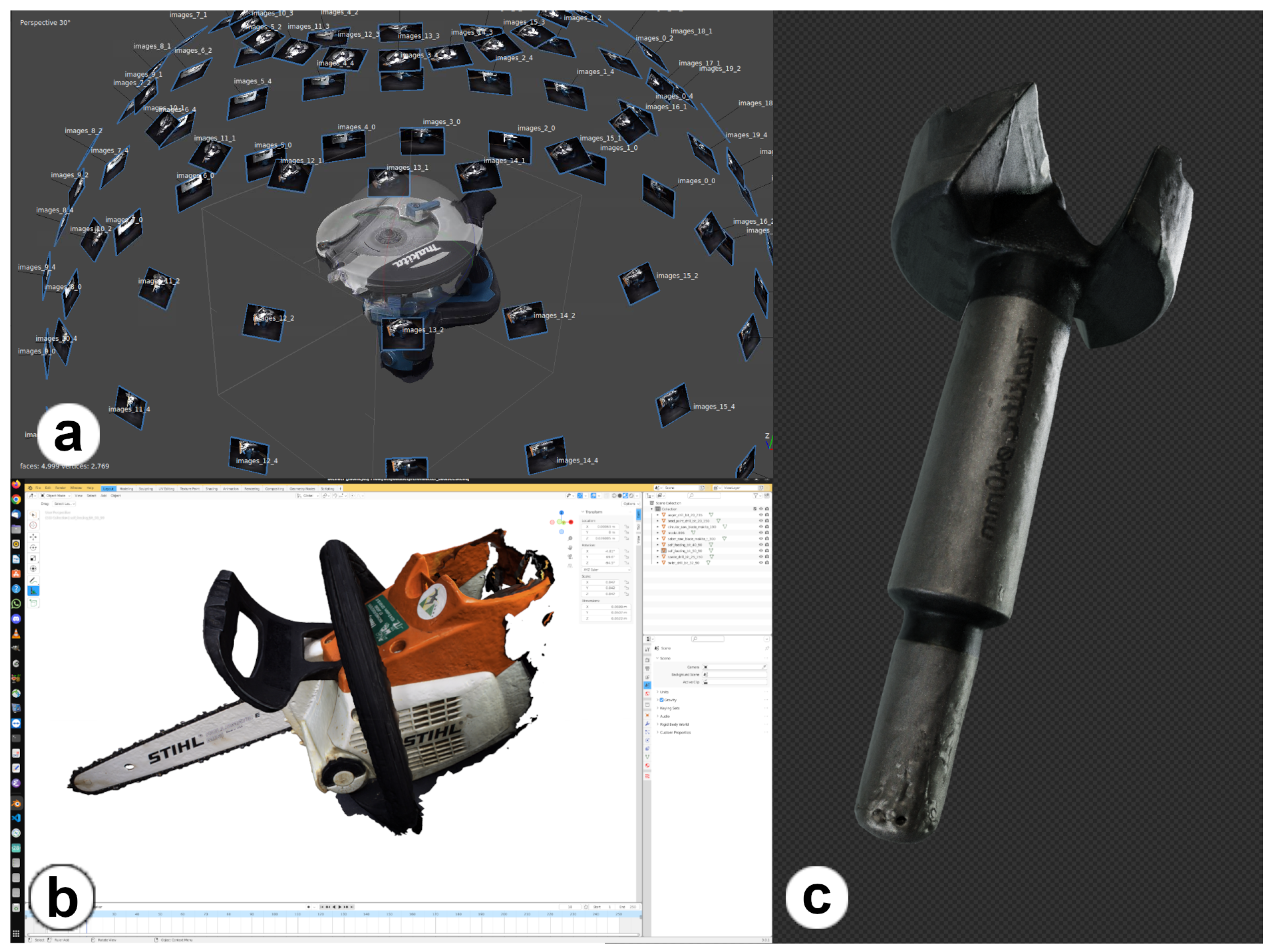
2.1. Dataset Digitization

To detect and track a given tool head, TTool requires a 3D mesh of the object. Hence, the very first stage of the TTool pipeline is the constitution of an entry dataset composed of a collection of the digital twins of the end effector that are later employed in the fabrication session. The accuracy of the reconstituted model is capital for the quality of pose detection. Moreover, a typical tool set necessary for a complete woodworking operation includes items with lengths spanning from 10 cm (e.g., an ordinary auger drill bit) to 1 m (e.g., chainsaw). We identify the structure-from-motion (SfM) technique as the most suitable and accessible scanning technique to obtain the digital twins of existing toolsets. We achieve this by capturing images of the tools from various perspectives. By doing this, we acquire images from all the semi-spherical angles (see Figure 4a). Once the image dataset is completed, the dense point cloud can be reconstructed, postprocessed, and finally meshed (see Figure 4b,c).
As of the current draft of this paper, we have made the set of scanned tools publicly available for use [39]. All the reconstructed models are stored in a TTool’s model manager responsible for facilitating the retrieval of these objects from all the different components of the software. Additionally, it acts as a bridge to obtain and update the current pose of the selected model. The model manager ensures synchronized model manipulation, preventing discrepancies when switching between tool heads.

2.2. Typology Detector

To estimate the pose of the tool head based on its digital model, the correct digital model must be selected first. To expedite this selection, we trained a classification model that can recognize the different tool heads and return a classification probability for each tool head based on the video feed from the camera. These probabilities are then used to display a list of tool heads in the user interface (UI), which is sorted from most to least likely. This means that the user can simply select the first entry in the list for a correctly classified tool head or one of the first couple of tool heads in the list if the model is uncertain. Since the tool heads have complex shapes and the background is uncontrolled, we decided to deploy a deep learning system and compared two of the standard architectures for image classification: ResNet18 [40] and EfficientNetV2S [41]. The two architectures were chosen over more recent larger models, because the inference has to run on the NUC, which has limited computational resources available. Both models were trained on a total of 10,879 images (see Figure 5). The dataset encompass images of nine different tool heads obtained through two distinct processes: first, images deliberately collected for training purposes. This involved mounting the camera on a specific tool and moving it to mimic the period preceding a carpenter’s commencement of the subsequent fabrication step. Second, additional images were extracted from videos recorded during test fabrications and manually classified. Notably, to prevent any leak of information between the validation and training datasets, the training and validation data were extracted from separate sets of videos in both scenarios. The preprocessing procedure commences by resizing the images to dimensions 384 × 384 and 256 × 256 using bi-linear interpolation for the EfficientNet and ResNet18, respectively. Subsequently, for ResNet18, a central crop to size 224 × 224 is applied. The pixel values are then rescaled to a range of 0–1. Following this, a channel-wise normalization is performed by subtracting the mean and dividing by the standard deviation. These statistical parameters are derived from the ImageNet1K v1 dataset [42], with means (R: 0.485, G: 0.456, B: 0.406) and standard deviations (R: 0.229, G: 0.224, B: 0.225). To increase the variability of our training data and make the model more robust, we augmented our data with random rotations, horizontal and vertical flips, and hue jittering.
Because of the comparatively small number of training images, we decided to employ transfer learning instead of training the networks from scratch. The weights were initialized with the weights provided by torchvision and trained on the ImageNet-1K v1 dataset [42]. We replaced the classification head with a custom one to match the number of tools and froze all of the weights, except for the classification head, while training. ResNet18 was trained for 28 epochs until convergence with a batch size of 90, while EfficientNet took only 10 epochs to converge with a batch size of 90. To assess the effectiveness of the classifiers, we determined their overall classification accuracy. This was achieved by calculating the ratio of accurately classified images within our validation dataset to the entire count of images in the same dataset. Our findings revealed that EfficientNet significantly surpassed ResNet18, achieving a 93% accuracy rate compared to ResNet18’s 43%. To gain deeper insights into EfficientNet’s performance, we subsequently analyzed the confusion matrix; Figure 6. This step was crucial to confirm that the high overall accuracy did not mask subpar performance on specific tools. It revealed that the network mostly struggles with the spade drill bit and similar tool heads of different sizes, e.g., the ⌀40 mm and ⌀50 mm self-feeding bits; Figure 6.
Some of our data originate from test fabrications. This makes them very realistic; however, it also means that the network can learn the appearance of the wooden beam in a given fabrication step to classify the tool head instead of the tool head’s topology. To ensure that the network uses the topology of the tool head for its decision, we computed class activation maps for the last convolutional layer using GradCAM [43]. The class activation maps (in Figure 7) show that the parts of the image containing the tool head had the largest impact on the classification result while objects in the background were ignored.
To employ additional tool heads, the model was retrained. This required deep learning knowledge and dedicated hardware in the form of a GPU. Since we cannot expect all users to have these prerequisites in terms of both hardware and digital literacy, we provided a web-based service for retraining the classifier with subsets of specific tool heads [44]. This service allows for the user to upload their own data for new tool heads and obtain custom-trained models for a specific application. Additionally, we reinforced the robustness and generalization capacity of the proposed model with synthetic data. The synthetic dataset was generated through Blender, and the designed add-on orchestrated the creation of an animation portraying tool heads in rotation while the camera moved. To elevate its authenticity, we implemented varied environmental lighting and incorporated metal brush effects into the 3D models. To further enrich the dataset, we introduced diverse adjustments in image temperatures and brightness levels; see Figure 8.

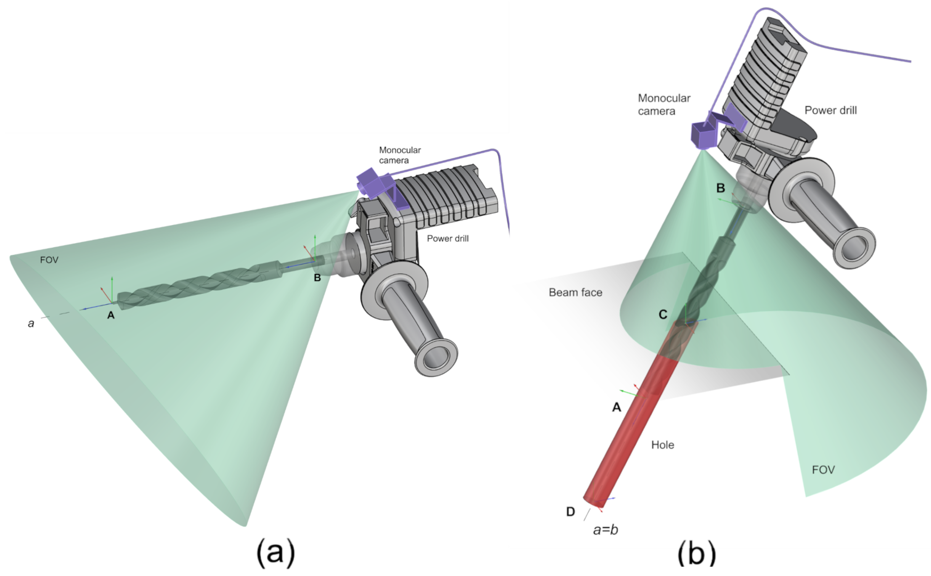
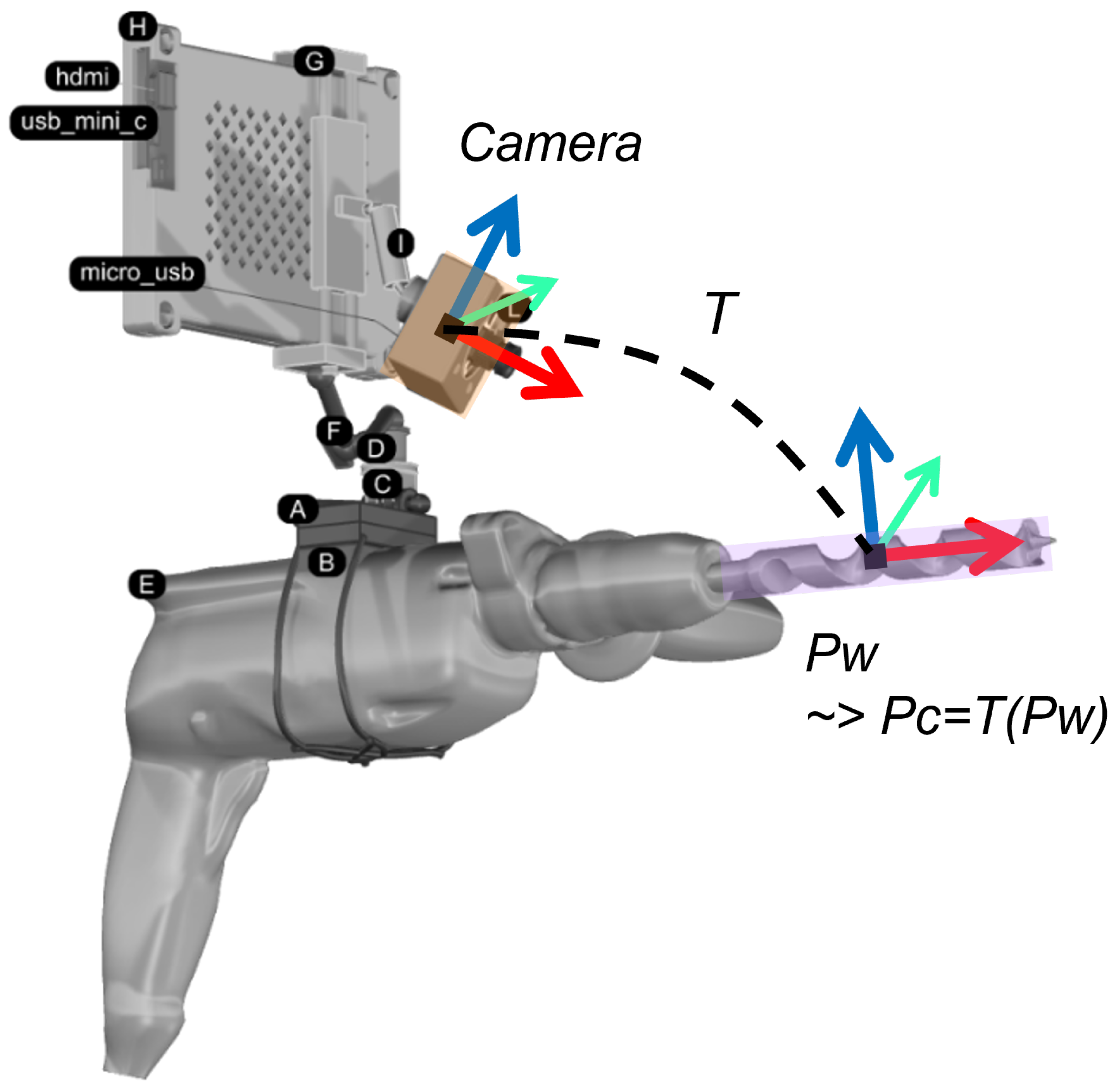
2.3. Global Pose Input

The component responsible for the input of the initial pose is defined by the operator’s input. In fact, obtaining the initial pose involves manual input from the user, offering a reliable and lightweight alternative to, for instance, deep learning approaches. At this point, TTool receives either the rotation in degrees and the rotation axis or the translation distance in pixels. It computes the transformation matrix and applies it to the current 3D model managed by the model manager (see Section 2.1). By allowing a global pose input via human–computer interaction, the algorithm can benefit from the human capacity while approximating a rough pose estimation.
The proposed global pose manipulator allows for the user to adjust the translation as well as the rotation on three axes (see Figure 9). The translation is performed on the world axis, whereas the rotation is performed on the local axis. We define the origin of the local axis as the mass center of the object, which aligns with its orientation. Each axis represents a specific direction in the object’s local coordinate system. We consider this presented approach to be more user-friendly, intuitive, and robust for the user to adjust the initial pose rather than deploying an AI-based one-shot approach. The following paragraph presents the global input mechanism in detail.
Each 3D object is characterized by its pose matrix T c m . This matrix represents the transformation of the object from the origin with translation t and rotation R. Additionally, the center of the model might be off the origin. That is, the center of each given model might not be exactly at the origin of the world axis. To address this, the normalization matrix T n is introduced. The last one translates the local model to the origin. On the one hand, the translation to the world axis can be expressed as the translation matrix applied to the model’s pose T c m . For rotation, on the other hand, local-to-world transformation is required. Given rotation axis A l o c a l , the local axis rotation is performed by transforming the local axis into world coordinate system A g l o b a l . Further, a rotation operation around A g l o b a l is applied next. For instance, rotating the model around the local z-axis produces A l o c a l = 0 0 1 . To perform these operations, a local axis transformation is first required.
A g l o b a l = T c m · T n · A l o c a l | 0
The local axis, represented by vector A l o c a l , is transformed from the object’s local to world coordinate system. This transformation takes into account the current pose of the object ( T c m ) and any normalization adjustments ( T n ). Note that the vector is assumed to always pass through the world’s origin and not yet be exactly at the center of the model. Next, the rotation is performed by translating the model to the origin of the world coordinate and rotating it around A g l o b a l . Finally, the model is translated back to its original position. We let C be the translation matrix from the origin to the center of the model in the world coordinate system and R be the rotational matrix around A g l o b a l . Rotated pose T c m is as follows:
T c m = C · R · [ C ] · T c m
To resume, the local axis is first transformed into the global coordinate system, and rotation is applied around the same transformed axis. This approach allows for precise control over the rotation of the object relative to its inherent orientation and structure. The transformation system’s callbacks are accessible via TTool’s API. In Section 3, we demonstrate how they can be embedded in a UI specifically designed for the evaluation campaign.

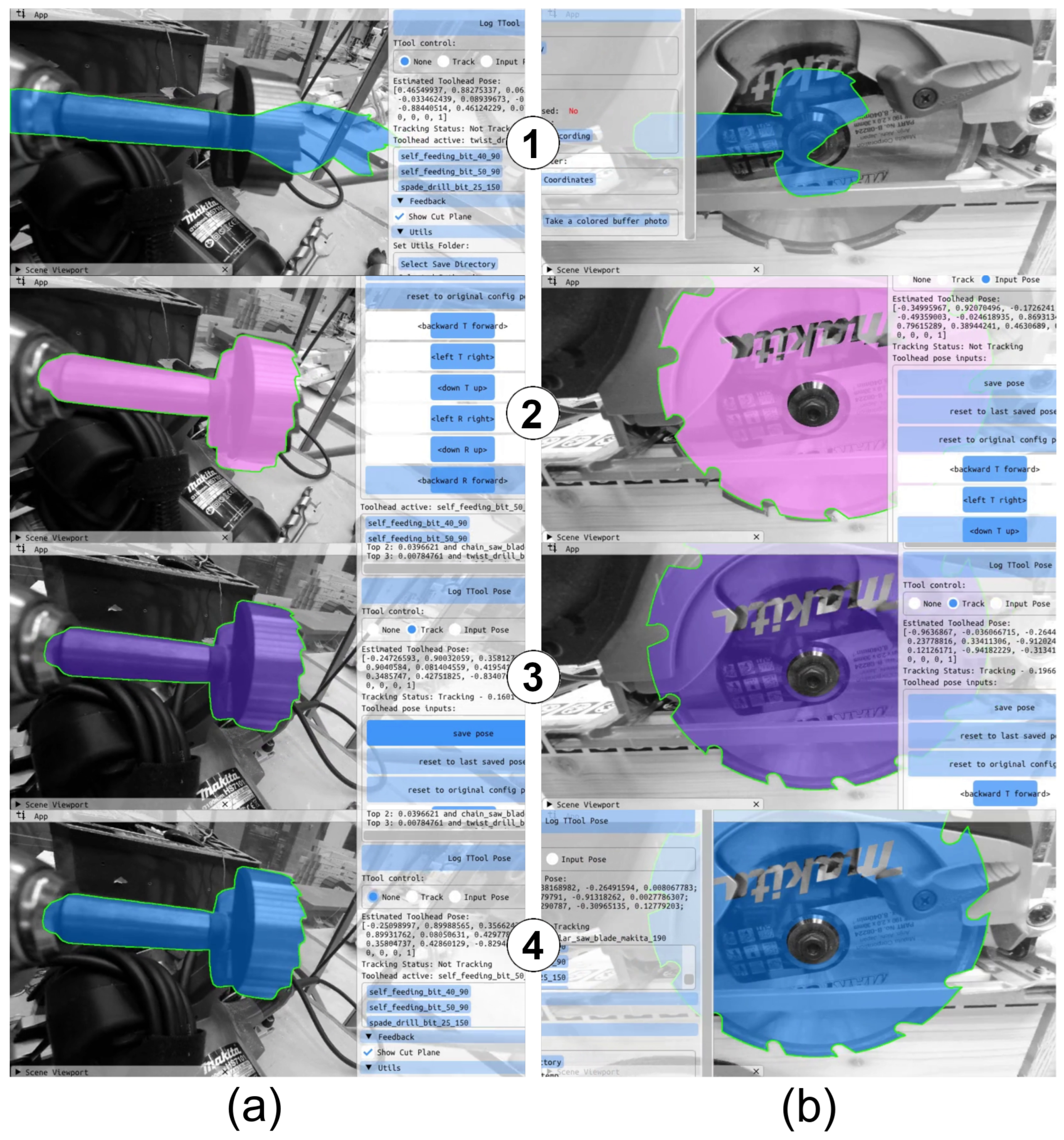
2.4. Supervised Pose Refiner

In the following phase of TTool, the approximated estimation of the pose provided by the user needs to be refined to fit perfectly the corresponding physical tool’s contour. To achieve this goal, we leveraged a modified version of a state-of-the-art pose refiner, SLET [20]. Necessary modifications were introduced to adapt the basic algorithm to our own study case and application scenario. The following is a description of our contributions to a modified version of the refiner and how human interaction is integrated into its functioning.
It is worth noting that the designated refiner requires only the camera’s RGB feed, making this phase particularly lightweight. In SLET [20], corresponding 2D–3D points are established by matching the contour points from the video frame (2D points) with the projected 3D model contour (3D points). SLET effectively addresses challenges such as occluding contour points, complex texture backgrounds, and other kinds of noise by leveraging probability computations. For each candidate contour point h i j , three probabilities are computed based on the color cue: the probability of h i j belonging to the foreground ( P ( h i j | F ) ), the probability of h i j belonging to the background ( P ( h i j | B ) ), and the probability of h i j being the actual contour ( P ( h i j | C ) ). To ensure the robustness of the selected contour points, SLET applies a filtering criterion to them. A candidate contour point is retained only when the probability of it being an actual contour point surpasses both the probability of it being in the foreground and it being in the background (Equation (3)).
P ( h i j | C ) > P ( h i j | F ) and P ( h i j | C ) > P ( h i j | B )
The refiner may lose track while attempting to update the pose on the current frame. In our setup, where the camera is fixed on the tool head (see Figure 10), a more effective strategy is either to maintain the current pose without updating it or to reset the pose to the best one previously specified by the user. This dual approach results in optimal performance due to the stationary nature of the tool heads relative to the camera. Hence, it is introduced in our version of the refiner.
Our investigation reveals a direct correlation between the P ( h i j | C ) of selected candidates and the tracking quality. When the tracker loses signal of the model, the average probability, denoted as P ( h i j | C ) , Equation (4), of the representing contours is observed to be low. A correlation between the value of 0.00625 and tracking loss is also found via experimental tests. Therefore, the object’s pose should reset to the initial pose. A value of 0.1 correlates with a low-quality update. Thus, the model should not update its pose to the new pose computed with these contours,
P ( h i j | C ) = 1 | C | h i j C P ( h i j | C )
where C is the filtered set of contour points. When tracking is lost, the negative feedback loop begins. In other words, an inaccurately oriented 3D model contour is employed for the subsequent pose computation. We use a semi-automatic adjustment to address this issue.
We introduce Algorithm 1 using the tracking score described above. In the event of tracking loss, the object pose is reset to its initial position, as this initial pose ( T i ) is expected to be near the current tool head’s location. This facilitates the tracker in regaining its tracking capability. When the tracking achieves a higher score, indicating the presence of several quality candidates for the newly computed pose ( T c m ), we proceed to update the pose. Alternatively, if the tracking score is lower, signifying a lack of robust candidates, we opt to freeze the tracking at the current pose.
Moreover, we provide users with the option to specify whether the current mode pose is precise and should serve as T i when tracking is lost. Users can also manually halt tracking; adjust the pose using the global pose input (Section 2.3) when the tracker completely loses track; or resume tracking to refine the pose from the initial pose ( T i ). With user supervision on the initial pose and during pose refinement, our modified SLET algorithm benefits from both the human dexterity and machine-like precision of the refiner to enhance the accuracy of the tool head’s pose.
Algorithm 1: Pose Update
Applsci 14 03011 i001
Once the user validates the pose refinement, TTool’s 6DoF detection is terminated, and woodworking fabrication can start. At this moment, the physical tool head is perfectly aligned with its corresponding 3D model. Most importantly, any occlusions and cluttering of the targeted object (e.g., a drill bit piercing into the wood, protection metal component hiding the circular saw blade, and simple wood chipping) do not affect the object locking achieved by TTool. This is a fundamental condition of AR fabrication, since feedback can also be computed when the tool head pierces or cuts through the wood (e.g., providing depth monitoring on when to interrupt the drilling operation), as shown in Figure 11.

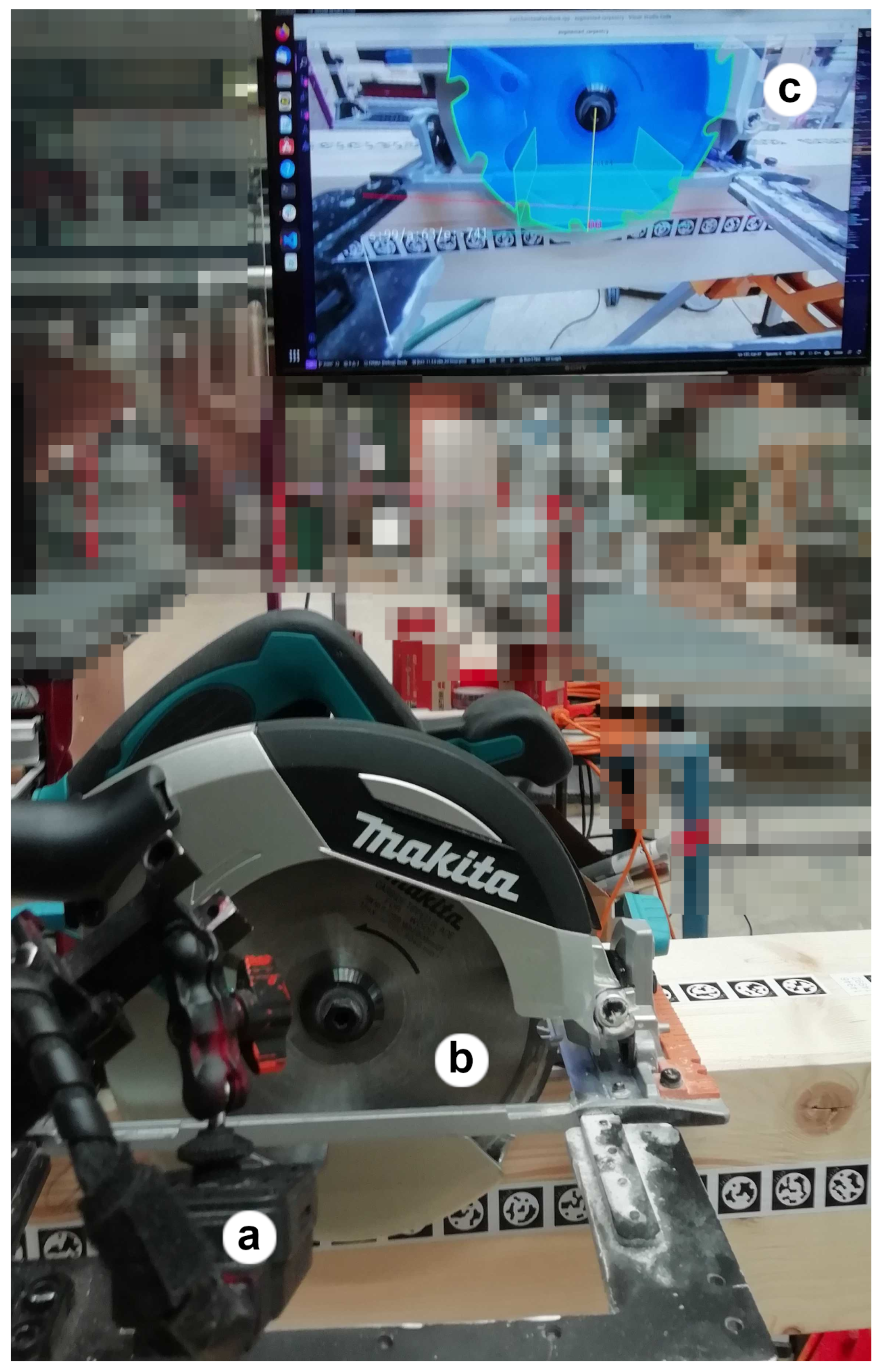
3. Experimental Campaign

3.1. Experimental Set-Up

We opted to assess TTool’s pose detection accuracy in actual workshop fabrication conditions. Due to the algorithm’s significant reliance on human–machine interaction and its sensitivity to real woodworking constraints (e.g., metallic objects, noise, varying lights, and abrupt change of backgrounds), the designed evaluation is based on live-captured feeds instead of rendered benchmarks on synthetic datasets. The evaluation source code is shared with the community and can be found in the public repository of the project [45]. In addition to gauging the accuracy and precision of the estimated 6DoF poses, we include a preliminary designed form to evaluate the user experience (UX). The cognitive load and interface usability represent important components of a supervised 6DoF pose detector, such as TTool. Users are engaging with displays and contemporary operating power woodworking tools. The UX benchmark is designed to fuse state-of-the-art references in the field of UX satisfaction benchmarks [46,47,48,49] but also physical load evaluators, such as the popular NASA-TLX index [50]. However, it is important to note that the current participant pool is limited to one person with no prior construction experience but who is a competent digital literate. Consequently, further testing with a more diverse and larger population sample size is essential for a comprehensive assessment of TTool’s UX.
To assess the precision of TTool’s pose detection, we utilize a mold that is meticulously referenced to a 3D model via the use of fiducial markers of type STag [51]. This particular fiducial marker is chosen due to its capacity to perform accurate pose detection, especially in cluttered views and steep view angles compared to other artificial markers [52,53,54]. This mold serves as a replica of a 3D model in execution, featuring accurately replicated slots and hole placements where physical tool heads can be inserted and compared. Once the mold is manufactured by computer numerical control (CNC), additional scanning is performed with the inserted tools to calibrate all fabrication inaccuracies and correct them in the 3D model (see Figure 12).
As part of this process, the user inserts the tool head into the designated slots. The alignment for this comparison is feasible, as TTool’s camera is calibrated via the detection of fiducial markers. This results in both the computed pose of the tool and the digital twin model sharing common reference points in the same coordinate system. Hence, GT can be determined by identifying common reference points between the tool head model and its negative counterpart, such as the spinning axis. This alignment method ensures a straightforward and reliable means of obtaining accurate measurements, as shown in Figure 13.
The user is tasked with determining the pose of 162 tool heads using TTool’s pipeline. The evaluation exercise comprises four sessions, each consisting of five assessment cycles per tool, with each cycle encompassing the utilization and pose detection of nine distinct tools. As shown in Figure 14, (a,b) is a self-feeding bit (of ⌀50 and ⌀40 mm), (c) a brad-point drill bit, (d) a twist drill bit, (e) a spade drill bit, (f,g) an auger drill bit (of ⌀20 and ⌀34 mm), (i) a circular saw with (a blade of 190 mm), (l) a sword saw, and finally (m) a chain saw. Further, the varying diameters of the self-feeding and auger drill bits are introduced to stress the system’s capacity under the same typology of tools but with slightly different dimensions (i.e., a maximum of 2 cm in diameter difference). We introduce this disturbance to reproduce a common condition in which varying dimensions of the same tool head’s shape are present in the same tool set.
The evaluation is conducted on NUC-running Ubuntu 22.04 LTS with an Intel 4-Core i7-1360P processor, 32 GB of RAM, and a seven-inch touchscreen device as the designated interface. The display is mounted on each tool owing to a magnetic attachment. Further, TTool is developed as a C++ console app and API for UNIX-based systems. Opting for a ×64 machine with a connected touchscreen device significantly streamlines the research process during software development and evaluation. In addition, utilizing a more ergonomic headset or phone would necessitate proprietary software (e.g., Unity) and considerable time dedicated to code wrapping in order to adapt the source code written in C++. The use of a touchscreen device allows for software evaluation while maintaining interoperability through the low-level nature of TTool’s source code. The UX interface was realized with DearImGui [55], a versatile free-bloat graphical user interface written in C++. The control panel occupies half of the display, whereas the other half presents an augmented view of the live feed (Figure 15). The user can control the 3-step TTool’s algorithm via the provided widgets while manipulating the woodworking tools. The interface allows to automatically detect the tool (see Figure 15c), manipulate the 3D object projection via a set of sliders (see Figure 15g), activate the pose refinement (see Figure 15e), and finally save the final pose (see Figure 15f).
From the user’s perspective, the evaluation is structured as follows: The user clips the display on the tool and adjusts the camera view to include the end effector (Figure 16a,b). The tool head is detected, and the user inputs an initial global pose, which is subsequently cached. The refiner is then activated (Figure 17) and interrupted by the user when it is in alignment (Figure 16c or Figure 18a). Finally, the tool head is positioned in the corresponding probing plate’s slot (Figure 16d or Figure 18b). At this moment, the GT and computed poses are referenced to the same coordinates and are ready to be saved on a disk (Figure 16e).
After completing the evaluation cycles, the output data can be postprocessed and analyzed, as elaborated in the following section.

3.2. Results

In this chapter, we present the postprocessing of the raw data obtained during the evaluation campaign, as well as the discussion and interpretation of the produced results. The benchmark raw and processed data are shared with the community and can be found in the public Zenodo repository of the project [56].
As illustrated in Figure 13a, we demonstrate how, for each evaluated pose, we can obtain TTool’s axis and its GT counterpart. To gauge position accuracy, we measure the Euclidean distance between the start and end points (Figure 19a,b) of the respective computed and GT axes. The mean of these distances is then calculated to provide a current comprehensive indicator of accuracy (Figure 19c). The rotational error is represented by the angle between the same two axes (Figure 19d).
Table 1 reports the values from Figure 19c,d. The presented summary reveals a generally coherent and compact distribution of results for both position and rotation error, which is indicative of consistent performance by TTool’s pose detector. However, it is noteworthy that the results for two distinct tool heads deviate from the overall trend: the auger drill bit (⌀35 mm) with a 12.85 mm error and the chain saw blade with a 10.61 mm error. The first is the result of false detection by the ML classifier (see Section 2.2). A user without any construction skills or knowledge is falsely guided by TTool to proceed with evaluating the wrong model. Two objects that differ in diameter by only 1 cm make it difficult for an inexperienced user to identify TTool’s misleading detection and correct it. The emergence of such errors highlights the necessity for enhancements in the model’s predictive capabilities in the same tool’s typology but of different sizes. Concerning the high error value of the chainsaw blade, a later inspection of the scanned model revealed inadequacies, specifically in its scaling, as evidenced by the approximate 2 mm error. This is because models obtained from photogrammetry are, by default, scaleless. Thus, manual scaling calibration is needed. This discrepancy significantly impacts the accuracy of pose detection. The inaccurately scaled scan undermines the proposed system, emphasizing ensuring a properly calibrated dataset. In both scenarios, it is evident that TTool’s rotation detection error is significantly less affected by an incorrect model than by a positional error. As a result, a drilling feedback loop is likely to be more reliably accurate than monitoring values, such as depth, which depend on the detected position of the tool head.
If we exclude the aforementioned tools from the summary, the accuracy of our evaluation pipeline yields mean position and rotation errors of 3.9 ± 1 mm and 1.19 ± 0.6°, respectively. The obtained rotation error value can be satisfactory within fabrication constraints. However, the positional error may be excessively high for woodworks, demanding more precision. Further, it is important to note that the positional error is significantly influenced by tolerances inherent in the physical aspects of the evaluation campaign, such as tag detection, CNC manufacturing, and wood deformations of the probing plate. Additionally, the scaling of the models, as observed, has a considerable impact on the positional error and requires thorough calibration. In summary, accounting for these additional tolerances, positional detection may exhibit better performance than indicated in the present results. Finally, the UX graphs provide insights that are distinct from the results of the rotation and positional error (Figure 20a,b). Notably, despite the auger drill bit of ⌀34 mm displaying higher errors compared to the other tools, it was rated comfortably in the UX assessments. In the tool-based questions, all tools received satisfactory ratings of four or five, except for the auger drill bit of ⌀20 mm, which was rated as three. This may indicate that user comfort and tool efficiency can, in this case, deviate from technically accurate measurements.
As highlighted earlier, the enhancement of UX should involve a more diverse tester population. However, focusing on this specific aspect, the suggested template study indicates that the revamped TTool experience is not only user-friendly but also minimally taxing, both physically and cognitively. Several factors contribute to this positive assessment. Consistency in tool usage and a fixed camera position allow the TTool system to efficiently cache the end effector’s pose, eliminating the need to repeatedly align and streamline the overall process. The algorithm’s straightforward logic facilitates easy alignment of the digitized tool with its physical counterpart, enabling users to rotate intuitively and position the tools. The tool detector demonstrates efficient identification in most cases, reducing the user’s need for manual tool selection. Finally, TTool’s refiner adeptly generalizes to the roughly initialized pose, ensuring swift alignment and machine-like precision.

4. Conclusions

In this paper, we presented TTool, a supervised and AI-assisted 6DoF pose detector for tool heads employed in woodworking operations. We demonstrated the importance of the 3D object detector TTool as a necessary component of any state-of-the-art AR application in the fabrication domain. We illustrated its functioning and the main components that constitute the algorithm. We evaluated performance in terms of pose accuracy through a physical evaluation campaign with a dedicated mock-up UI and hardware and suggested a template for UX evaluation for future studies. The results report a rotational error that is inferior to 2°, a positional error assumedly in the range of 2 mm, and a preliminary satisfactory user experience evaluation.
While our proposed method holds promise for advancing tool localization and pose detection, there are notable limitations and avenues for improvement. One critical consideration revolves around the implications of implementing a global pose detector. While a global pose detector could eliminate the need for manual input poses, potential negative effects and trade-offs must be carefully evaluated. Additionally, exploring alternative ML models that may offer improved performance or better alignment with our application remains an avenue for future research. The evaluation results, while providing a broad understanding of system accuracy, must be interpreted with caution due to the high variance introduced by the physical and contextual evaluations. Future research could involve integrating the system into a comprehensive design-to-fabrication framework to assess its performance in a more holistic context, thereby gauging the ultimate impact on the fabricated piece itself. To address practical challenges, we recognize the need for a more efficient and robust dataset acquisition process. The current methodology’s sensitivity to scale adjustments emphasizes developing a more resilient system that can withstand variations in scale calibration and dataset acquisition. Ideally, 3D models can be openly sourced from fabricators, simplifying AR operations by not having to collect scans of the user’s own tool heads. TTool is developed to propose a reliable alternative for object detection in augmented subtractive fabrication processes in timber construction. TTool is specifically tailored to target monocular RGB sensors, a typology that is the most versatile in our opinion and that possesses the greatest potential for widespread adoption. Through the incorporation of AI assistance and intuitive AR processes, as demonstrated by TTool, we illustrated how a hybrid approach with human dexterity, AI reconnaissance, and traditional computer vision algorithms offers a robust and complementary alternative to full automation. The work presented here is just one facet of what we envision as a comprehensive AR application in woodworking. Ongoing development includes an adapted simultaneous localization and mapping (SLAM) system, generative fabrication instructions, and a complete interface, which will soon be showcased as part of an integrated software platform incorporating TTool.

Author Contributions

Conceptualization: A.S.; methodology: A.S. and N.C.; software: A.S., N.C. and F.A.; validation: A.S.; formal analysis: A.S. and J.G.; investigation: A.S. and N.C.; resources: J.G. and Y.W.; data curation: A.S.; writing—original draft preparation: A.S. and N.C.; writing—review and editing: A.S., N.C., F.A. and J.G.; visualization: A.S.; supervision: J.G. and Y.W. All authors read and agreed to the published version of the manuscript.

Funding

This research received no external funding.

Institutional Review Board Statement

Not applicable.

Informed Consent Statement

Not applicable.

Data Availability Statement

The source code can be obtained in the public repository of the project [45]. The tool heads dataset [39] and the ML service [44] are also shared with the community.

Acknowledgments

We thank the EPFL for their support and technical advice on matters of image analysis throughout the development of the research project. We also acknowledge Nicolas Richard from the SCITAS EPFL, who contributed to this study with CMake refactoring and optimization, and Nazgul Zholmagambetova, who contributed with the evaluation campaign and evaluation. The authors acknowledge the financial support of the EPFL and finally the Structural Engineering Group of the EPFL for their assistance.

Conflicts of Interest

There are no conflicts of interest.

Abbreviations

The following abbreviations are used in this manuscript:
TToolTimberTool
AECArchitecture engineering and Construction
ARAugmented reality
6DoFSix degrees of freedom
HMDHead-mounted Display
GTGround truth
SfMStructure from motion
PnPPerspective-n-points
RANSACRandom sample consensus
UXUser experience
CNCComputer numerical control manufacturing
SLAMSimultaneous localization and mapping

References

  1. Sandy, T.; Giftthaler, M.; Dorfler, K.; Kohler, M.; Buchli, J. Autonomous repositioning and localization of an in situ fabricator. In Proceedings of the 2016 IEEE International Conference on Robotics and Automation (ICRA). IEEE, Stockholm, Sweden, 16–21 May 2016. [Google Scholar] [CrossRef]
  2. Sandy, T.; Buchli, J. Object-Based Visual-Inertial Tracking for Additive Fabrication. IEEE Robot. Autom. Lett. 2018, 3, 1370–1377. [Google Scholar] [CrossRef]
  3. Mitterberger, D.; Dörfler, K.; Sandy, T.; Salveridou, F.; Hutter, M.; Gramazio, F.; Kohler, M. Augmented bricklaying. Constr. Robot. 2020, 4, 151–161. [Google Scholar] [CrossRef]
  4. Kriechling, P.; Roner, S.; Liebmann, F.; Casari, F.; Fürnstahl, P.; Wieser, K. Augmented reality for base plate component placement in reverse total shoulder arthroplasty: A feasibility study. Arch. Orthop. Trauma Surg. 2020, 141, 1447–1453. [Google Scholar] [CrossRef]
  5. Cartucho, J.; Wang, C.; Huang, B.; Elson, D.S.; Darzi, A.; Giannarou, S. An enhanced marker pattern that achieves improved accuracy in surgical tool tracking. Comput. Methods Biomech. Biomed. Eng. Imaging Vis. 2021, 10, 400–408. [Google Scholar] [CrossRef]
  6. Sin, M.; Cho, J.H.; Lee, H.; Kim, K.; Woo, H.S.; Park, J.M. Development of a Real-Time 6-DOF Motion-Tracking System for Robotic Computer-Assisted Implant Surgery. Sensors 2023, 23, 2450. [Google Scholar] [CrossRef]
  7. Hein, J.; Cavalcanti, N.; Suter, D.; Zingg, L.; Carrillo, F.; Farshad, M.; Pollefeys, M.; Navab, N.; Fürnstahl, P. Next-generation Surgical Navigation: Multi-view Marker-less 6DoF Pose Estimation of Surgical Instruments. arXiv 2023, arXiv:2305.03535. [Google Scholar] [CrossRef]
  8. Settimi, A.; Gamerro, J.; Weinand, Y. Augmented-reality-assisted timber drilling with smart retrofitted tools. Autom. Constr. 2022, 139, 104272. [Google Scholar] [CrossRef]
  9. Kriechling, P.; Loucas, R.; Loucas, M.; Casari, F.; Fürnstahl, P.; Wieser, K. Augmented reality through head-mounted display for navigation of baseplate component placement in reverse total shoulder arthroplasty: A cadaveric study. Arch. Orthop. Trauma Surg. 2021, 143, 169–175. [Google Scholar] [CrossRef] [PubMed]
  10. Hasegawa, M.; Naito, Y.; Tone, S.; Sudo, A. Accuracy of augmented reality with computed tomography-based navigation in total hip arthroplasty. J. Orthop. Surg. Res. 2023, 18, 662. [Google Scholar] [CrossRef]
  11. Wu, P.C.; Wang, R.; Kin, K.; Twigg, C.; Han, S.; Yang, M.H.; Chien, S.Y. DodecaPen: Accurate 6DoF Tracking of a Passive Stylus. In Proceedings of the 30th Annual ACM Symposium on User Interface Software and Technology, Quebec City, QC, Canada, 22–25 October 2017. [Google Scholar] [CrossRef]
  12. Tsukada, S.; Ogawa, H.; Nishino, M.; Kurosaka, K.; Hirasawa, N. Augmented reality-based navigation system applied to tibial bone resection in total knee arthroplasty. J. Exp. Orthop. 2019, 6, 44. [Google Scholar] [CrossRef]
  13. Tsukada, S.; Ogawa, H.; Kurosaka, K.; Saito, M.; Nishino, M.; Hirasawa, N. Augmented reality-aided unicompartmental knee arthroplasty. J. Exp. Orthop. 2022, 9, 88. [Google Scholar] [CrossRef]
  14. Zhang, L.; Ye, M.; Chan, P.L.; Yang, G.Z. Real-time surgical tool tracking and pose estimation using a hybrid cylindrical marker. Int. J. Comput. Assist. Radiol. Surg. 2017, 12, 921–930. [Google Scholar] [CrossRef]
  15. Gadwe, A.; Ren, H. Real-Time 6DOF Pose Estimation of Endoscopic Instruments Using Printable Markers. IEEE Sensors J. 2019, 19, 2338–2346. [Google Scholar] [CrossRef]
  16. Harris, C.; Stennett, C. RAPID—A video rate object tracker. In Proceedings of the British Machine Vision Conference, Oxford, UK, 1 September 1990. [Google Scholar] [CrossRef]
  17. Drummond, T.; Cipolla, R. Real-time visual tracking of complex structures. IEEE Trans. Pattern Anal. Mach. Intell. 2002, 24, 932–946. [Google Scholar] [CrossRef]
  18. Wang, B.; Zhong, F.; Qin, X. Robust edge-based 3D object tracking with direction-based pose validation. Multimed. Tools Appl. 2018, 78, 12307–12331. [Google Scholar] [CrossRef]
  19. Zhong, L.; Lu, M.; Zhang, L. A Direct 3D Object Tracking Method Based on Dynamic Textured Model Rendering and Extended Dense Feature Fields. IEEE Trans. Circuits Syst. Video Technol. 2018, 28, 2302–2315. [Google Scholar] [CrossRef]
  20. Huang, H.; Zhong, F.; Sun, Y.; Qin, X. An Occlusion-aware Edge-Based Method for Monocular 3D Object Tracking using Edge Confidence. Comput. Graph. Forum 2020, 39, 399–409. [Google Scholar] [CrossRef]
  21. Xiang, Y.; Schmidt, T.; Narayanan, V.; Fox, D. PoseCNN: A Convolutional Neural Network for 6D Object Pose Estimation in Cluttered Scenes. arXiv 2017, arXiv:1711.00199. [Google Scholar] [CrossRef]
  22. Simpsi, A.; Roggerini, M.; Cannici, M.; Matteucci, M. 6 DoF Pose Regression via Differentiable Rendering. In Lecture Notes in Computer Science; Springer: Berlin/Heidelberg, Germany, 2022; pp. 645–656. [Google Scholar] [CrossRef]
  23. Li, Y.; Wang, G.; Ji, X.; Xiang, Y.; Fox, D. DeepIM: Deep Iterative Matching for 6D Pose Estimation. Int. J. Comput. Vis. 2019, 128, 657–678. [Google Scholar] [CrossRef]
  24. Xu, Y.; Lin, K.Y.; Zhang, G.; Wang, X.; Li, H. RNNPose: Recurrent 6-DoF Object Pose Refinement with Robust Correspondence Field Estimation and Pose Optimization. In Proceedings of the 2022 IEEE/CVF Conference on Computer Vision and Pattern Recognition (CVPR), New Orleans, LA, USA, 18–24 June 2022. [Google Scholar] [CrossRef]
  25. Palazzi, A.; Bergamini, L.; Calderara, S.; Cucchiara, R. End-to-End 6-DoF Object Pose Estimation Through Differentiable Rasterization. In Computer Vision—ECCV 2018 Workshops; Springer: Berlin/Heidelberg, Germany, 2019; pp. 702–715. [Google Scholar] [CrossRef]
  26. Park, K.; Mousavian, A.; Xiang, Y.; Fox, D. LatentFusion: End-to-End Differentiable Reconstruction and Rendering for Unseen Object Pose Estimation, 2019. In Proceedings of the IEEE/CVF Conference on Computer Vision and Pattern Recognition (CVPR), Seattle, WA, USA, 14–19 June 2020. [Google Scholar] [CrossRef]
  27. Bukschat, Y.; Vetter, M. EfficientPose: An efficient, accurate and scalable end-to-end 6D multi object pose estimation approach. arXiv 2020, arXiv:2011.04307. [Google Scholar] [CrossRef]
  28. Wang, G.; Manhardt, F.; Tombari, F.; Ji, X. GDR-Net: Geometry-Guided Direct Regression Network for Monocular 6D Object Pose Estimation. In Proceedings of the 2021 IEEE/CVF Conference on Computer Vision and Pattern Recognition (CVPR), Nashville, TN, USA, 20–25 June 2021. [Google Scholar] [CrossRef]
  29. Di, Y.; Manhardt, F.; Wang, G.; Ji, X.; Navab, N.; Tombari, F. SO-Pose: Exploiting Self-Occlusion for Direct 6D Pose Estimation. In Proceedings of the 2021 IEEE/CVF International Conference on Computer Vision (ICCV), Montreal, BC, Canada, 11–17 October 2021. [Google Scholar] [CrossRef]
  30. Tekin, B.; Sinha, S.N.; Fua, P. Real-Time Seamless Single Shot 6D Object Pose Prediction. In Proceedings of the 2018 IEEE/CVF Conference on Computer Vision and Pattern Recognition, Salt Lake City, UT, USA, 18–23 June 2018. [Google Scholar] [CrossRef]
  31. Peng, S.; Zhou, X.; Liu, Y.; Lin, H.; Huang, Q.; Bao, H. PVNet: Pixel-Wise Voting Network for 6DoF Object Pose Estimation. IEEE Trans. Pattern Anal. Mach. Intell. 2022, 44, 3212–3223. [Google Scholar] [CrossRef] [PubMed]
  32. Zakharov, S.; Shugurov, I.; Ilic, S. DPOD: 6D Pose Object Detector and Refiner. In Proceedings of the 2019 IEEE/CVF International Conference on Computer Vision (ICCV), Seoul, Republic of Korea, 27 October–2 November 2019. [Google Scholar] [CrossRef]
  33. Chen, B.; Chin, T.J.; Klimavicius, M. Occlusion-Robust Object Pose Estimation with Holistic Representation. In Proceedings of the 2022 IEEE/CVF Winter Conference on Applications of Computer Vision (WACV), Waikoloa, HI, USA, 3–8 January 2022. [Google Scholar] [CrossRef]
  34. Tremblay, J.; To, T.; Sundaralingam, B.; Xiang, Y.; Fox, D.; Birchfield, S. Deep Object Pose Estimation for Semantic Robotic Grasping of Household Objects. arXiv 2018, arXiv:1809.10790. [Google Scholar] [CrossRef]
  35. Tjaden, H.; Schwanecke, U.; Schomer, E.; Cremers, D. A Region-Based Gauss-Newton Approach to Real-Time Monocular Multiple Object Tracking. IEEE Trans. Pattern Anal. Mach. Intell. 2019, 41, 1797–1812. [Google Scholar] [CrossRef] [PubMed]
  36. Li, J.; Wang, B.; Zhu, S.; Cao, X.; Zhong, F.; Chen, W.; Li, T.; Gu, J.; Qin, X. BCOT: A Markerless High-Precision 3D Object Tracking Benchmark. In Proceedings of the 2022 IEEE/CVF Conference on Computer Vision and Pattern Recognition (CVPR), New Orleans, LA, USA, 18–24 June 2022. [Google Scholar] [CrossRef]
  37. Wu, P.C.; Lee, Y.Y.; Tseng, H.Y.; Ho, H.I.; Yang, M.H.; Chien, S.Y. [POSTER] A Benchmark Dataset for 6DoF Object Pose Tracking. In Proceedings of the 2017 IEEE International Symposium on Mixed and Augmented Reality (ISMAR-Adjunct), Nantes, France, 9–13 October 2017. [Google Scholar] [CrossRef]
  38. De Roovere, P.; Moonen, S.; Michiels, N.; Wyffels, F. Dataset of Industrial Metal Objects. arXiv 2022, arXiv:2208.04052. [Google Scholar] [CrossRef]
  39. Settimi, A.; Naravich; Gamerro, J.; Weinand, Y. TTool-dataset, Version v36; CERN: Genewa, Switzerland, 2023. [Google Scholar] [CrossRef]
  40. He, K.; Zhang, X.; Ren, S.; Sun, J. Deep Residual Learning for Image Recognition. arXiv 2015, arXiv:1512.03385. [Google Scholar]
  41. Tan, M.; Le, Q.V. EfficientNetV2: Smaller Models and Faster Training. arXiv 2021, arXiv:2104.00298. [Google Scholar]
  42. Deng, J.; Dong, W.; Socher, R.; Li, L.J.; Li, K.; Fei-Fei, L. ImageNet: A Large-Scale Hierarchical Image Database. In Proceedings of the CVPR09, Miami, FL, USA, 20–25 June 2009. [Google Scholar]
  43. Selvaraju, R.R.; Cogswell, M.; Das, A.; Vedantam, R.; Parikh, D.; Batra, D. Grad-CAM: Visual Explanations from Deep Networks via Gradient-Based Localization. Int. J. Comput. Vis. 2019, 128, 336–359. [Google Scholar] [CrossRef]
  44. Aymanns, F.; Zholmagambetova, N.; Settimi, A. ibois-epfl/TTool-ai: V1.0.1: First TTool-AI Release; CERN: Genewa, Switzerland, 2024. [Google Scholar] [CrossRef]
  45. Settimi, A.; Naravich, C.; Nazgul, Z. Software of TTool: A Supervised AI-Assisted Visual Pose Detector for AR Wood-Working; CERN: Genewa, Switzerland, 2024. [Google Scholar] [CrossRef]
  46. Danielsson, O.; Syberfeldt, A.; Brewster, R.; Wang, L. Assessing Instructions in Augmented Reality for Human-robot Collaborative Assembly by Using Demonstrators. Procedia CIRP 2017, 63, 89–94. [Google Scholar] [CrossRef]
  47. Aromaa, S.; Frangakis, N.; Tedone, D.; Viitaniemi, J.; Aaltonen, I. Digital Human Models in Human Factors and Ergonomics Evaluation of Gesture Interfaces. Proc. Acm. Hum. Interact. 2018, 2, 1–14. [Google Scholar] [CrossRef]
  48. Kildal, J.; Martín, M.; Ipiña, I.; Maurtua, I. Empowering assembly workers with cognitive disabilities by working with collaborative robots: A study to capture design requirements. Procedia CIRP 2019, 81, 797–802. [Google Scholar] [CrossRef]
  49. Gutierrez, L.E.; Betts, M.M.; Wightman, P.; Salazar, A.; Jabba, D.; Nieto, W. Characterization of Quality Attributes to Evaluate the User Experience in Augmented Reality. IEEE Access 2022, 10, 112639–112656. [Google Scholar] [CrossRef]
  50. Hart, S.G.; Staveland, L.E. Development ofNASA-TLX (Task Load Index): Results of Empirical and Theoretical Research. In Human Mental Workload; Elsevier: Amsterdam, The Netherlands, 1988; pp. 139–183. [Google Scholar] [CrossRef]
  51. Benligiray, B.; Topal, C.; Akinlar, C. STag: A stable fiducial marker system. Image Vis. Comput. 2019, 89, 158–169. [Google Scholar] [CrossRef]
  52. Bergamasco, F.; Albarelli, A.; Rodola, E.; Torsello, A. RUNE-Tag: A high accuracy fiducial marker with strong occlusion resilience. In Proceedings of the CVPR, Colorado Springs, CO, USA, 20–25 June 2011. [Google Scholar] [CrossRef]
  53. Bergamasco, F.; Albarelli, A.; Cosmo, L.; Rodola, E.; Torsello, A. An Accurate and Robust Artificial Marker Based on Cyclic Codes. IEEE Trans. Pattern Anal. Mach. Intell. 2016, 38, 2359–2373. [Google Scholar] [CrossRef]
  54. Kalaitzakis, M.; Cain, B.; Carroll, S.; Ambrosi, A.; Whitehead, C.; Vitzilaios, N. Fiducial Markers for Pose Estimation. J. Intell. Robot. Syst. 2021, 101, 71. [Google Scholar] [CrossRef]
  55. Cornut, O. Dear ImGui: A Bloat-Free Graphical User Interface Library for C++. 2023. Available online: https://github.com/ocornut/imgui (accessed on 2 February 2023).
  56. Settimi, A. TTool: Evaluation Raw Data and Results, Version v1.0.0; CERN: Genewa, Switzerland, 2024. [Google Scholar] [CrossRef]
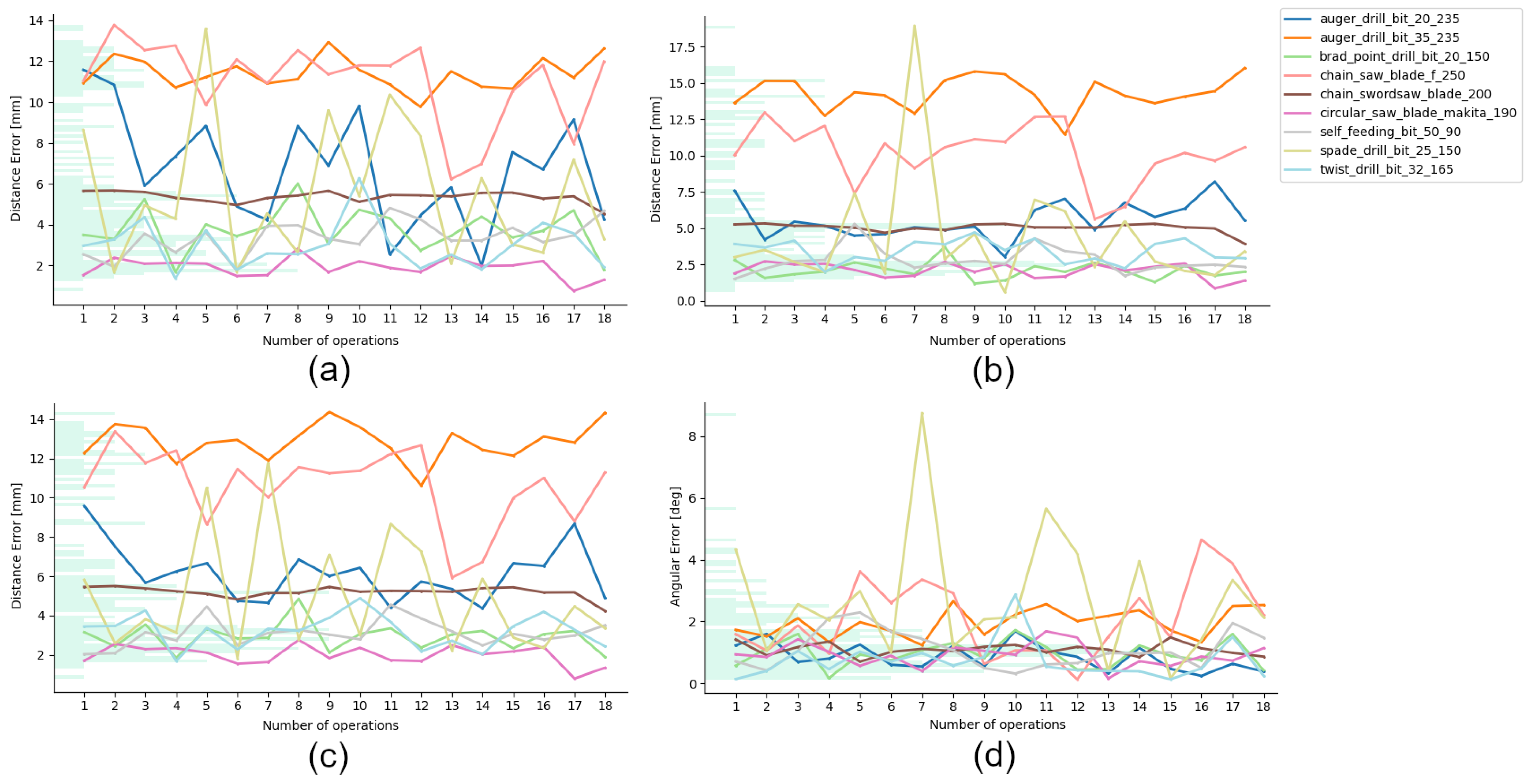
Figure 1. Early developments of TTool and circular saws: (a) monocular RGB camera, (b) circular saw blade, and (c) camera live feed augmented with TTool’s detection widgets. Since the blade’s pose is punctually detected, the targeted object can later be obstructed (e.g., here, through blade protection) without interfering with the tracking.
Applsci 14 03011 g001
Figure 2. Screenshots from each phase of the TTool pipeline for (a) drill bits and (b) blades. (1) The tool is manually inserted, but the corresponding 3D model is not yet paired. (2) The ML classifier detects the tool, and the loaded model is manipulated by the user to a satisfactory initial pose. (3) TTool’s refiner optimizes the input pose until the user decides to interrupt the operation. Finally, (4) the pose is validated, and the 3D model is locked in place, becoming resilient to obstructions and the dynamic background.
Applsci 14 03011 g002
Figure 3. (a) TTool detects and localizes the 3D model of a given tool head within the mounted camera’s frame. (b) Once localized and object-locked, even if the end effector is occluded by the timber during cutting or drilling operations, it is still possible to inform the AR system of its position. In fact, during such events, TTool is deactivated but conserves the registered pose and can run again once the tool head’s contours are again fully visible.
Applsci 14 03011 g003
Figure 4. (a) In the absence of production CAD models, tool heads can be easily digitized via the structure-from-motion (SfM) technique. (b) Nevertheless, raw captured point clouds need to be postprocessed via third-party software. (c) Finally, only the tool head needs to be isolated and meshed in a watertight fashion.
Applsci 14 03011 g004
Figure 5. Examples of images fed to the proposed model (on the left are sawing tools, and on the right are drill bits).
Applsci 14 03011 g005
Figure 6. Confusion matrix computed on the validation dataset for EfficientNet. The overall classification accuracy is 93%.
Applsci 14 03011 g006
Figure 7. Class activation maps computed with GradCAM show that the part of the images containing the tool heads has the largest impact on the classification (corresponding to the warmest colors).
Applsci 14 03011 g007
Figure 8. (a) Animation frames of four drill bits present in the synthetic dataset. (b) Example of synthetic and augmented data generated from a drill bit. The tool head’s model and its textures are obtained from the scanning process via photogrammetry. The procedural rendering is achieved owing to a specially designed add-on for Blender.
Applsci 14 03011 g008
Figure 9. TTool can detect the 6DoF pose of a tool head via a monocular sensor installed on a power tool. To achieve this, the object must initially be positioned within the camera’s frame and subsequently undergo refinement by the user.
Applsci 14 03011 g009
Figure 10. Given that the monocular sensor is mounted (1) and fixed (2) on the board of the power tool, the tool head remains static in the background (3). TTool’s refiner can adjust for the tracked tool head’s correct pose during sudden movements and vibrations.
Applsci 14 03011 g010
Figure 11. An example of (a) drilling and (b) sawing operations with TTool: (a) 1. The pose of the drill bit is detected via TTool. (a) 2,3. Once the drill bit is locked to its 3D model, piercing the wood or any other form of occlusion does not influence object locking. (a) 4. Once extracted, TTool can be re-initialized to swiftly refine the pose of the drill bit.
Applsci 14 03011 g011
Figure 12. Illustration of the CAD drawing for the probing plate, in which the blue stripes indicate tags calibrated to the locations of the slots. Following fabrication, the recalibration of slots and holes was performed using scans from physical tools inserted into the corresponding slots.
Applsci 14 03011 g012
Figure 13. Illustration of the evaluation system to obtain ground truth (GT) data via the digital twined set-up: (a) The axis of the estimated pose (green) is compared with the one from the model (pink) and the physical model (blue), which can be considered coincident once the operator calibrates the tool to the probing plate shown in (b) and the bottom view shown in (c).
Applsci 14 03011 g013
Figure 14. Selection of the tools considered for the evaluation: (a,b) self-feeding bits; (c) brad-point drill bit; (d) twist drill bit; (e) spade drill bit; (f,g) auger drill bits; (h) drill; (i) circular saw; (l) sword saw; and (m) chainsaw.
Applsci 14 03011 g014
Figure 15. Overview of the UX interface designed specifically for the evaluation of TTool: (a) the projection of the 3D model of the sword saw’s plate to be tracked; (b) the sword saw; (c) button to activate the TTool classifier; (d) the classifier reordering the library of tools from the highest to the lowest prediction score; (e) the set of widgets to switch between during the tracking and manual input phases; (f) the controls to save the pose or reinitialize it; and (g) the 3D transformation bars divided by rotation axis and translation axis.
Applsci 14 03011 g015
Figure 16. Evaluation of the TTool pipeline for chainsaw: (a) The user clips the display and sensor to the tool. (b) The camera is adjusted to include a chainsaw’s plate in the frame. (c) The tool is first detected by AI, and the pose is initialized by the user and refined automatically. (d) The user inserts the tool into the manufactured slot. (e) Finally, the pose is exported to a disk for later analysis.
Applsci 14 03011 g016
Figure 17. Sample frames from all the evaluated tool heads during TTool’s refinement stage.
Applsci 14 03011 g017
Figure 18. (a) The user calls the AI detector, initializes an initial pose, and refines the pose automatically. (b) Once the user is satisfied with the detected pose, the blade is inserted into the slot of the probe plate, and TTool’s pose is exported.
Applsci 14 03011 g018
Figure 19. Graphs reporting the errors for (a) the base tip, (b) the tool tip, (c) the mean position, and (d) the mean rotation. On the x-axis, we present the error expressed in millimeters or degrees, whereas the x-axis indicates a thick for each cycle of tested operations for a total of 18 rounds for each tool head.
Applsci 14 03011 g019
Figure 20. Overview of the results for the user evaluation of TTool: (a) UX progress-based question graph and (b) tool-based question graph.
Applsci 14 03011 g020
Table 1. Resuming the error metrics for all 162 operations of the datasets grouped by category of tag layers and densities where * is the angular error and ** is the positional error.
Tool Name (-)Number of Operations (-)Mean Rotation Error * (°)Mean Position Error ** (mm)
Drill auger ⌀20180.85 ± 0.426.17 ± 1.38
Drill spade ⌀25182.74 ± 2.044.97 ± 2.91
Drill auger ⌀35181.96 ± 0.4512.85 ± 0.91
Drill brad point ⌀20180.95 ± 0.432.92 ± 0.69
Drill twist ⌀32180.73 ± 0.623.21 ± 0.83
Drill self-feeding ⌀50181.09 ± 0.593.09 ± 0.67
Circular sawblade180.92 ± 0.371.99 ± 0.48
Sword sawblade181.1 ± 0.25.2 ± 0.28
Chain sawblade182.08 ± 1.2110.61 ± 1.93
Disclaimer/Publisher’s Note: The statements, opinions and data contained in all publications are solely those of the individual author(s) and contributor(s) and not of MDPI and/or the editor(s). MDPI and/or the editor(s) disclaim responsibility for any injury to people or property resulting from any ideas, methods, instructions or products referred to in the content.

