
Conformal 3D Material Extrusion Additive Manufacturing for Large Moulds


Department of Industrial Engineering (DIN), University of Bologna, Viale Risorgimento 2, 40136 Bologna, Italy
*
Author to whom correspondence should be addressed.
Appl. Sci. 2023, 13(3), 1892; https://doi.org/10.3390/app13031892
Submission received: 20 December 2022
/
Revised: 27 January 2023
/
Accepted: 30 January 2023
/
Published: 1 February 2023
(This article belongs to the Section Additive Manufacturing Technologies)
Abstract
:Industrial engineering applications often require manufacturing large components in composite materials to obtain light structures; however, moulds are expensive, especially when manufacturing a limited batch of parts. On the one hand, when traditional approaches are carried out, moulds are milled from large slabs or laminated with composite materials on a model of the part to produce. In this case, the realisation of a mould leads to adding time-consuming operations to the manufacturing process. On the other hand, if a fully additively manufactured approach is chosen, the manufacturing time increases exponentially and does not match the market’s requirements. This research proposes a methodology to improve the production efficiency of large moulds using a hybrid technology by combining additive manufacturing and milling tools. A block of soft material such as foam is milled, and then the printing head of an additive manufacturing machine deposits several layers of plastic material or modelling clay using conformal three-dimensional paths. Finally, the mill can polish the surface, thus obtaining a mould of large dimensions quickly, with reduced cost and without needing trained personnel and handcraft polishing. A software tool has been developed to modify the G-code read by an additive manufacturing machine to obtain material deposition over the soft mould. The authors forced conventional machining instructions to match those of an AM machine. Thus, additive deposition of new material uses 3D conformal trajectories typical of CNC machines. Consequently, communication between two very different instruments using the same language is possible. At first, the code was tested on a modified Fused Filament Fabrication machine whose firmware has been adapted to manage a milling tool and a printing head. Then, the software was tested on a large machine suitable for producing moulds for the large parts typical of marine and aerospace engineering. The research demonstrates that AM technologies can integrate conventional machinery to support the composite materials industry when large parts are required.
1. Introduction
Large-scale moulds are typically required in marine and aerospace engineering to produce structural parts in composite materials. For large-scale items, a primitive model, usually handcrafted by trained technicians or obtained through CNC operations, is used to create a unique female mould: the model is covered in wax, using a gel coat which gives a polished surface, and the lamination process starts. Layers of composite materials with increasing areal weight are deposed on the model to obtain a rigid and strong structure. Then, an external layer of gel coat resin is applied over the parts in composite material to waterproof the final product, aid in mould ejection, ensure the aesthetic appearance, and provide colouring. The part can be eventually cured in an autoclave to obtain high breaking stresses, or the composite can be polymerised at room temperature. The mould and model accuracies are constrained by the artisan worker’s skill and experience, which can vary significantly across the sector. Typical raw materials machined for moulds and male models are medium density plastic and UREOL.
Obtaining suitable moulds requires trained personnel and accurate polishing, and nowadays, in the marine sector, the average workforce required is around 10 h for one squared meter of mould to carry out surface smoothing [1]. When a traditional approach is followed, numerous steps are required to create a part in composite material, including the need for writing a G-code [2] program using Computer-Aided Manufacturing (CAM) software.
The industrial community is therefore asking scientific research for new strategies in developing machines that can perform several tasks to reduce human interaction and speed up quality-related processes [3]. It is also worth noting that the use of epoxy or polyester resins poses a threat to the safety of the operators due to toxicity problems. Using a face mask with filters may reduce comfort during the summer or in case of prolonged use. Moreover, environmental factors push towards reducing waste of resins and fabric, which can be quite hard to recycle with current technologies and can severely harm nature if not correctly disposed of. Therefore, the automatisation of mould production assumes a high relevance for the marine and aerospace sectors: this is especially true for marine engineering, where polyester resins are used, which are more toxic than the epoxy ones used in aerospace. In this context, Additive Manufacturing (AM) technology can help to produce moulds more reliably while lowering the cost of tooling and production time [4].
Additive Manufacturing (AM) has seen a significant rise in popularity over the past 20 years due to its evident industrial benefits, becoming more popular in academia and science [5]. AM techniques represent a broad group of procedures in which new material is deposited, joined, or solidified, frequently layer by layer, under computer control. Design flexibility, a shorter design-to-manufacturing cycle, the ability to generate complicated designs without being constrained by limitations in the manufacturing process (such as undercuts, squared holes and pockets, variable density, and trabecular structures), the elimination of joints and connections, and the decrease in wasteful raw material usage are only a few of the benefits of AM. Researchers have developed methods for component production using AM technology, particularly for small batches or prototypes [6]. Among different industrial applications that have shown rising appeal in AM, the naval industry’s attention to AM technology has also recently increased. In particular, it enables the creation of models and moulds to assist the manufacturing of composite material items with an excellent level of finish and accuracy for large-scale components with an exceptional level of detail, such as boats [7,8].
For example, 3D-printed moulds have been used to create polyurethane foam components for the marine and automotive industries [9,10]. The source [9] describes 3D-printed ABS material moulds manufactured using the FFF technology to produce polyurethane automotive components. For effective foam demolding, the surface roughness of the mould has received special consideration, where chemical polishing has been checked using a pull-off test demonstrating that AM techniques can be effectively used to make moulds. The paper [10] introduces the Foam Additive Manufacturing (FAM) technique based on the direct production of naval components, such as large-scale moulds, and explores the use of foam-printed material to produce a hull mould. The stages of the FAM technology-based process, which employs a layered material deposition strategy, are covered, as well as the progression from the CAD models to the robot programming.
However, surface finish quality, part accuracy, material limitations, residual stress-causing deformation, and velocity are drawbacks of AM compared to traditional processes, such as Computer Numerically Controlled (CNC) machining [11] based on chip removal. Particularly for Fused Filament Fabrication (FFF), component orientation on the platform and path planning affect mechanical properties (such as tensile strength, elastic modulus, and compressive strength) [12]. Surface finishing is a painstakingly manual post-process in FFF, but it can be planned as part of the automated manufacturing process in CNC machining.
CNC machining is a subtractive manufacturing method that uses tools to remove materials from slabs to create the desired shape. It allows for the precise and accurate production of complex shapes. Compared to AM machines, CNC machines are more expensive, thus entailing a more significant upfront investment, and trained operators are required to operate the machine. However, when dealing with large production volumes of components, costs decrease in a significant way [13].
The complementary nature of these two technologies can be noticed when the strength and weaknesses of AM and CNC machining are compared. Although both technologies use a tool that follows a path specified in a G-code file [14], CNC milling and AM are independent technologies with distinctly separate logic that are challenging to merge. Indeed, new material is added in the AM to obtain the final shape, while raw material is removed from a slab in the CNC process. However, the G-code file listing the machine’s instructions to obtain the intended shape can be considered the common attribute between these two different technologies.
Thus, the research community concentrated on the hybrid manufacturing approach to boost production efficiency, which allows both additive and subtractive processes to coexist [15,16,17]. For example, the literature has typically combined AM and machining procedures to obtain small details on large-scale components [18,19] or improve part accuracy [20]. Moreover, as described in this research, it is possible to apply AM to the creation of moulds. The customizability [21], reduction of waste materials, and geometric flexibility [22] offered by AM technology are valuable points of strength that can be exploited in conjunction with conventional techniques for mould manufacturing.
To contribute towards new manufacturing strategies with minimal human intervention in mould fabrication, this research proposes a methodology for conformal material deposition to improve the current technology and support the transition to more effective and environmentally friendly production processes. Developing a reliable machine integrating AM and milling has the potential to produce moulds directly without a primitive model: in this way, manufacturing costs can be reduced, and human intervention can be reduced, while preserving operator’s health.
This paper describes a hybridisation between AM machines based on the FFF technique and G-code used in CNC machines to manufacture 3D moulds allowing the conformal deposition of material. The conceptual methodology has been preliminarily tested on a small commercial FFF machine customised for the sake of this research to manufacture two test parts. The Do It Yourself (DIY) design of a hybrid manufacturing machine is not new in the scientific community [23], but its application to manufacturing high-precision moulds has not been described in detail. Based on the outcome of this research, the methodology herein developed is feasible and has been applied to a large material deposition AM machine. This device has been developed to support the manufacturing of large moulds for composite material lamination. The case study perfectly fits the real-life context where mould production’s time and economic impact on the final product can be high, especially for small lots. Often in aerospace and marine engineering, small lots are produced, and in some cases, quite a few products are manufactured.
The novelty of this research lies in developing a methodology that combines a 3D conformal FFF, rarely explored before, for the production of moulds in combination with traditional machining. It is worth noting that 3D paths for FFF machines are rarely explored in literature, as the reference [24] confirms, but they can improve the manufacturing process with high potential. To achieve conformal FFF, the authors simplified an existing CAM post-processor to force traditional machining instructions to resemble those of an AM machine. This processing makes it feasible to use 3D trajectories, typically only available to CNC machines, to communicate between two different philosophies using a single language. This idea consists of a traditional machine that includes an AM aspect with the ground-breaking capacity to make moulds without manufacturing a primitive model, managed by codes allowing the conformal deposition of fused/melted material. Thus, it reduces the model’s cost and makes this technology appealing for small productions.
The paper is structured as follows. After this introduction, the paper in Section 2 presents in detail the methodology proposed in this research. Section 3 describes the tests on an FFF machine customised to test the procedure developed and obtain the conformal deposition of layered materials in 3D. Furthermore, Section 4 includes comments on the tests carried out, both software and hardware. Finally, Section 5 ends the paper by discussing the proposed methodology’s main achievements and future developments.
2. Materials and Method
The methodology proposed in this study is based on dividing the different phases of manufacturing a typical large-scale mould into different materials with which a different machining process is associated. After the CNC milling of the supporting structure, the additive phase can be seen as a virtual CNC machining with the extruder’s size equal to a virtual tool used for surface finish machining. Thus, a single G-code and a single machine can be used to manufacture the structure, increasing the efficiency of the overall manufacturing workflow. The milled core of PVC (PolyVinyl Chloride) or polystyrene acts as a support for the additive deposition of the external coating. Therefore, the use of support material, typical of the FFF process, can be avoided entirely, minimising post-process actions of operators to remove unneeded material and optimising material deposition in a conformal way, meaning that fused material continuity is assured.
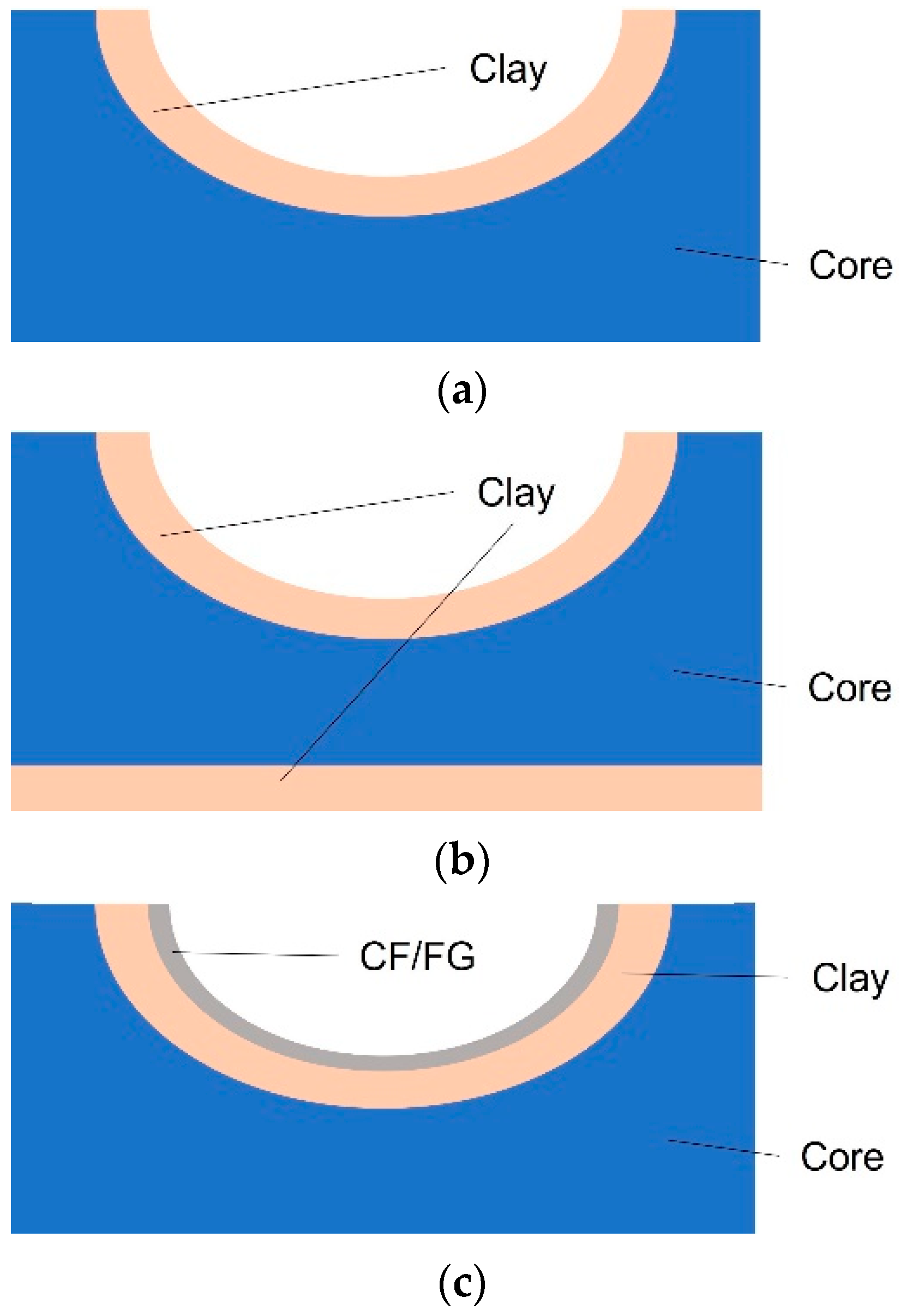
Different parts and moulds could be manufactured directly with a single hybrid machine. For example, a core of expanded PVC, milled with a traditional process, can support the additively manufactured coating deposition with PLA, PETG, or clays for large structures. Expanded PVC foam board is a lightweight, rigid PVC sheet used for various applications, including marine structures [25], interior design, thermoforming, prototypes, model making, and much more. It can be easily machined with the low power needed. A schematic representation of the structures obtained with the proposed methodology can be seen in Figure 1.
Furthermore, the machine manages the component’s surface polish, thus reducing human intervention. Before starting with the lamination of the layers of composite material which will build up the parts, skilled operators are only required to examine the mould’s dimensions and quality in the final step. Indeed, a typical hybrid manufacturing machine is equipped with the two following tools: a spindle with interchangeable milling tools for roughing, finishing, and polishing; an extruder nozzle for extruding clay or filament.
The hybrid processing method described in this research is based on milling a slab of raw material during the early stage after the 3D digital model is available. The same machine then facilitates the additive deposit of the coating on the support’s exterior surface along 3D paths computed by the proposed methodology. For the sake of clarity, a graphical representation of the general workflow proposed in this research is shown in Figure 2.
The G-code is an example of a machine-readable language based on a series of tasks to be carried out. It includes the path’s definition and the settings required for the machine: how quickly to move, along what trajectory to take in the available space, and many other settings. The G-code file can be automatically compiled using CAM software for the traditional processes and slicing software for the AM machines.
While Computer-Aided Design (CAD) software is used to design products, CAM software packages enable users to obtain processing cycles that begin with raw materials slabs and end with the manufactured CAD-designed object. The CNC machine’s different settings, such as the feed rates, cutting speeds, and other cutting parameters, are converted by CAMs into G-codes before the machine starts running.
In the design of the hybrid manufacturing machine, particular attention should be given to the geometry restrictions related to potential collisions between the extruder head and walls of machined mould in concave parts. In this research, an optimal design of endstop positions and relative distance between the additive and subtractive tools avoid dangerous impacts.
Moreover, it is essential to pay attention to the frame of reference of the coordinates in the G-code instructions when utilising a single G-code to control several tools that are not in the exact location of the machine. Finding the relative distance between the subtractive tool head and the extruder requires special consideration (Figure 3). The following instructions are used to add this data to the G-code:
where nnn is the distance between the tools’ positions in mms along the three axes.
G0 Xnnn Ynnn
G92 X0 Y0 Znnn
A typical structure/mould manufactured using the proposed methodology consists of an assembly given by a core and one or more external coatings, as seen in Figure 1. Using the composite structure shown in Figure 1a as a reference and according to the flowchart shown in Figure 2, the user will first create the digital model of the internal core of foam material (e.g., expanded PVC) with a curved upper surface skin body. The next stage involves the digital model of an external shell of a few millimetres, which is necessary to produce the external coating layers using AM techniques along novel conformal paths. The separate digital bodies are then correctly positioned in an assembly file and must be exported as separate files from CAD software. By doing this, the separate models may be loaded into CAM software with the appropriate relative distances and frames of reference.
Traditional FFF uses a Layered Manufacturing (LM) method that reflects a noticeable stair-step effect (Figure 4a). This phenomenon might be especially problematic when making moulds for high-performance applications such as aerospace, marine, or automotive industries, where highly smooth external surfaces are required for aerodynamic/fluid-dynamic/structural purposes. A conformal 3D spatial deposition of fused material can represent a crucial strategy to enhance the manufacturing of the external coating of moulds. Instead of planar paths, the filaments are deposited along curved (basically non-horizontal) routes, which suggests an entirely new building strategy for FFF (Figure 4b).
Curvilinear (non-horizontal) material deposition has been discussed in earlier scientific works about AM [26,27]. However, to the best of the authors’ knowledge, modifying a milling 3-axis G-code instruction for usage with an AM machine has not been adequately addressed in the scientific community.
In particular, the proposed methodology uses as input a G-code file obtained with a modified “CncMasters-Metric” post-processor [28] of CAM software and uses a virtual tool of the same diameter as the nozzle of the hybrid machine that mimics a finishing process. The “CncMasters-Metric” post-processor for a 3-axis machine has been chosen for the project’s aim because the G-code layout is very similar to the AM layout. The 3D CAD models are converted through CAM software into G-code instructions using the modified post-processor according to the user’s needs.
The authors concentrated on integrating conformal 3D curved paths for AM in addition to eliminating the support material in conventional Fused Filament Fabrication (FFF) procedures. Indeed, a traditional FFF machine only moves the Z axis when there is a layer change and moves the X and Y axes simultaneously. This approach is critical when good strengths are required because high anisotropy affects the final object [29]. Therefore, this research aims to build a 3-axis hybrid machine to cope with the drawbacks of the typical 2.5D material deposition, such as the high stair-step effect, the need for support material, high surface roughness, and strong anisotropy.
Similarly to what is performed in bioengineering [30,31,32], a conformal FFF allows the direct construction of intrinsically curved 3D surfaces during the material deposition phase. This 3D freeform printing process involves a secondary supporting material. Freeform printing paths derived from customised G-codes conform precisely to the surface profile of the supporting material.
A surface finishing machining G-code can be utilised as a template to achieve this goal. Indeed, the surface finishing is a fully 3-axis operation, requiring the machine’s three axes to move simultaneously. However, it is crucial to alter the typical CNC G-code layout to contain the E letter for every single coordinate’s value after each line of code to make the 3-axis code suitable for AM rather than chip removal. The E letter is the standard in AM for the control of the extrusion process and expresses the amount of extruded material during the movement of the hot-end. The following subsection describes the methodology used to achieve such a customised G-code.
2.1. Spatial Material Deposition
The milling process in the G-code file is used as input for the proposed methodology. It can be seen as a surface finishing that removes a constant height of raw material from a slab with movements along three axes. The removed material’s height should equal the desired layer height of the deposed external coating. A visual flowchart (Figure 5) describes the methodology step by step to make it reproducible in future studies.
As shown by the flowchart, a custom-made code can read the input CNC G-code file to read and save the spatial coordinates of points belonging to the tool path. In parallel, the code opens a new G-code file in writing mode. The user is asked to input some values about the extrusion process: the desired number of layers of external coating, the layer height, the extrusion temperature, the extrusion speed, and so on. These values are reported following the ISO G-code language for the AM process. Then, for two consecutive points of the path (i.e., point 0 and point 1 of coordinates () and () respectively), the code is capable of evaluating the length of the path covered by the tool by comparing their coordinates along the three main axes:
Then, the tool displacement is multiplied by a factor called ‘extrusion multiplier’ () to evaluate the amount of extruded material for each row of the G-code. This factor is essential to achieve a filament line width of the manufactured object that should be equal to the desired one. The value of can be easily found experimentally manufacturing a simple test benchmarking object.
Comparing the total amount of extruded material of a G-code evaluated by traditional AM slicing software and the own-made G-code using an initial trial value, it is possible to find the correct extrusion multiplier value.
Once the amount of extruder material for each row is evaluated, the code writes in output a new G-code with a typical FFF layout: G0 Xnnn Ynnn Znnn Ennn where nnn represents a coordinate value. This operation is carried out for all movements of each layer. When a layer change occurs, a retraction has been inserted before moving and executing the new layer. This way, stringing is reduced, specifically when tiny plastic strings remain on a 3D-printed item. This often happens when the extruder moves to a new spot and plastic leak out of the nozzle.
Therefore, obtaining a 3D additive deposition of raw material is possible using a simple code. However, CAM milling G-code must first be created to use a virtual tool that mimics the extruder’s size for surface finish machining. The presence of a solid core previously milled using the same machine provides physical support for the 3D deposition of new material. Additionally, by altering the tool pass angle with respect to the slab’s origins, it is possible to construct several surface finishing processes on the same surface and produce a layered texture that crosses the nozzle’s motion directions.
2.2. Customised Desktop Hybrid Manufacturing Machine
A scaled-size prototype of a hybrid machine has been constructed to validate the hybrid manufacturing approach suggested in the previous paragraph and assess its benefits and drawbacks. A straightforward case study involving the creation of a small mould has been considered.
A 3Drag FFF cartesian machine has been chosen to validate the proposed methodology [33]. The FFF machine has a 200 × 200 × 200 mm building volume, a nominal resolution of 0.015 mm in the X and Y axes and 0.039 mm in Z, and a heated bed. However, the latter characteristic is not vital for this research. Thus, the heated bed has been disconnected; indeed, large-scale hybrid manufacturing machines for mould fabrication do not require a heated bed. The choice fell on this machine because kits are available online to convert it from a 3D printer to a CNC machine.
The FFF machine has been modified to host a low-power drill/grinder with a power of 130 W, a rotation speed of 10,000–33,000 rpm and a flexible shaft. Thus, a bracket has been designed, printed with PLA material, and fixed to the X rail of the machine near the extrusion head (Figure 6). The bracket is assembled with a butterfly screw anchor to easily adjust the height of the spindle during the AM process to avoid dangerous collisions because of the considerable exposed length of the spindle.
The position of the CNC tool should comply with requirements such as:
- the spindle should not disturb the operations of the nozzle during 3D printing;
- univocal (X, Y) positioning of the tool during the entire manufacturing cycle;
- it should be removable if necessary;
- it should be as close as possible to the extrusion head not to waste a portion of the working area.
Moreover, the end-stops of the hybrid manufacturing machine have been modified to optimise the motion of the tools. Initially, the AM machine recognised the position closest to the bed as the extruder Z home position, which can cause problems. Indeed, when the hot end moves to the Z home, it could hit the core material or the structure that was previously milled and not removed from the bed. The position of the end stop of the Z axis has been changed by fixing it at the top; this framework design prevents possible conflicts between the extruder head and walls in case of concave shapes. A support was designed to host it and allow it to be fixed to the Z gantry. Accordingly, the machine firmware has been updated with the “MarlinKimbra” version because it better meets the project’s needs.
The following section of the paper describes a practical application to validate the methodology using a case study dealing with manufacturing two small parts to proxy the actual fabrication of a mould and the lamination of CF efficiently.
First, a simple sandwich structure made of two 3D-printed external shells (one at the bottom and one at the top) and a milled core of expanded PVC has been manufactured according to the scheme shown in Figure 1b. The external shells were produced using a traditional LM approach to verify the functionality of the hybrid desktop machine. PLA has been chosen for the external shells because it does not necessarily require a heated surface to stick on the printing bed, while an expanded PVC board has been selected for the structure’s core.
The second test is used to validate the spatial material deposition methodology described in Section 2.1. A down-scaled mould structure, similar to what is represented in Figure 1c, has been manufactured. PLA mimics the CFRP deposition along 3D conformal paths over the PVC milled board. Between these two materials, the deposition of some layers of PolyVinyl Alcohol (PVA), a commercial filament soluble in water, aims to simulate the release agent spread manually over the moulds. According to the needs of the described case studies, Table 1 collects the printing settings used to extrude PVA and PLA for the desktop FFF hybrid machine.
2.3. Large-Scale Hybrid Manufacturing Machine
The proposed methodology can be reproduced in large-scale hybrid manufacturing machines, as demonstrated in the following paragraph. Indeed, the composite lamination on moulds manufactured following a conformal approach gives advantages in terms of stiffness and strength of the mould itself. This is particularly true in the case of moulds with remarkable dimensions, typical of marine, aerospace, or automotive applications.
Consequently, the software developed for the material deposition AM machine has been tested on a large-scale AM–CNC machine capable of producing moulds up to 5 m. This final test has been carried out to verify the possibility of using the proposed approach on industrial machines. Indeed, the approach was applied to a large-scale CNC own-built gantry machine with a 5 × 3 × 2 m working area to prove the practical implication of the discussed methodology. A T-Max 657 extrusion machine from Graco company [34] has been selected for this specific research. A large-size nozzle extrudes the Raku-Tool Cp 6070 modelling clay, and the outlet diameter is tuned depending on the material used in the moulds’ manufacturing [35]. To provide the reader with some data, the range of nozzle dimensions used to manufacture the large-scale sample test goes from 0.8 to 1.2 mm in diameter for the tested materials. The machine is built around an IndraMotion MTX Micro actuation system and is managed through the Bosch Rexroth human-machine interface without any change in the hardware. The axes are moved by three brushless motors Indra Dyn S QSK061; a customised PLC board manages the extruder.
The requirements for milling in terms of axis speed and stiffness are more significant than those required in additive manufacturing mode. From the software point of view, a re-compilation of the Bosch Rexroth control environment was necessary to read the new hybrid G-code developed for the sake of this research: the human–machine interface was not modified, but only the lines of the code in which the CNC machine control software acquires the G-code.
An overall recap of the tests performed on the desktop and the large-scale machines is shown in Figure 7, along with the materials used for each layer of the final mould.
As the results will demonstrate, the methodology herein developed is feasible and can be extended to sizeable 3D printing machines where the impact of the cost of the moulds on the final products can be high, similar to what is described in [36]. Compared to traditional mould manufacturing, the proposed approach uses AM and CNC tools to produce moulds with a more efficient workflow; indeed, the integration of a conformal 3D spatial deposition boosts the efficient coating deposition over the moulds.
3. Results
In order to test the functionality of the hybrid desktop machine, a conventional sandwich structure that consists of two 3D-printed outer skins (one at the bottom and one at the top) and a machined interior of expanded PVC has been fabricated. The expanded PVC has been chosen because of its ease of machining, even with low-power milling tools. Figure 8 shows different stages of the manufacturing process. Once the first base shell is manufactured, the CNC tool machines the core board (Figure 8a) using different milling devices for different machining stages.
During the production process, the CNC spindle is precautionarily raised to avoid collisions between the spindle itself and the PVC board during the final AM process. Indeed, this manual intervention does not affect the manufacturing process because the AM phase is entirely independent from the spindle position. As a final step, a top shell made in PLA has been extruded using a traditional layered manufacturing approach to validate the functionality of the hybrid machine. In Figure 8f, it is possible to see that using an LM approach, the quality of the external surface is poor; thus, a conformal FFF could enhance the quality of the final models.
During the manufacturing of this first test, manual intervention was required to spread the epoxy resin over the lower PLA shell and correctly assemble the expanded PVC slab. However, adding a nozzle for resin deposition and adding a new layer could bring a fully automated process.
Once the proper machine’s functionality has been evaluated, a down-scaled mould structure, similar to Figure 1c, has been manufactured. In particular, a 110 × 110 mm expanded PVC board supports the entire structure. The PVC board is milled using an end-mill and a ball-mill tool for surface finishing creating a double-curved shape, as seen in Figure 9a. An assembly jig, made in PLA material, fixes the board’s position on the machine during the manufacturing phase (Figure 9b).
Once the PVC board has been obtained, the production process continues with the deposition of an external skin over the milled support, according to the schematic structure shown in Figure 1c. The mould is manufactured in this test, and the final part in FFF is a layer of wax deposited between the mould and the part. This skin should be easily detached from its mould, similar to how a Carbon Fiber (CF) laminate is detached from the mould. Indeed, this case study aims to replicate the fabrication process of a structure that could reproduce an actual manufacturing cycle and have practical implications. In order to avoid deformations such as warping, which are typical of AM, it is necessary to use a material that, when applied to the surface of the mould, allows the necessary adhesion to keep the printed model in place while also allowing the part to be detached without damaging the mould. The idea is to deposit some layers of soluble material, such as PVA, and then manufacture the final laminate with the required material. PVA is often used in dual nozzle FFF machines as a support material without requiring a heated bed, and it can be easily discarded without damaging the external surfaces of the components [37].
The 3D FFF of coating and final laminate has been carried out as the last step. Thus, it was necessary to create the virtual surface finish CAM machining previously. In particular, four surface finishing operations have been prepared on the same surface in which the only parameter that varies is the angle of the tool pass with respect to the piece’s origins, according to the methodology described in the previous section. This way, a layered texture can be created by crossing the directions in which the nozzle moves. Four milling operations have been prepared with an angle of 0°, 45°, −45°, and 90°. For the specific case study, the authors considered it reasonable to create two codes: one with two layers for PVA (at 0° and 90°) that mimic the release agent and one with four layers for PLA (at 0°, 45°, −45°, and 90°) that mimic the final laminate.
The 3D FFF deposition of PLA along different directions is visible in Figure 10a, while the final laminate is visible in Figure 10b. At the end of the manufacturing process, the assembly was immersed for a couple of hours in hot water. On the one hand, the final PLA laminate came off without issues, while on the other, the PVC mould has not been damaged and is ready to be reused for other production cycles.
The developed software has been used to manufacture a large-scale mould using additive material deposition of modelling clay following spatial paths (Figure 11). Indeed, filaments of a few millimetres in diameter, typical of traditional FFF technology, would reflect an extremely long manufacturing time.
The resulting moulds have been finished using two milling operations: first, a rough milling operation is applied to remove exceeding material clay (Figure 12a); then, an accurate finishing process is carried out to obtain the ready-to-be-used large-scale mould (Figure 12b). This automatic machine was designed to carry out various operations on huge components and to establish reliable support for the industrial production of numerous parts made of composite material. An effective workflow is followed to complete several workmanships, which begins with the creation of the mould support through material removal using a standard CNC machine. The next phase is characterised by the AM process, during which a material crust is deposited to prepare the surface for the creation of the finished composite item. This manuscript describes the methodology up to the mould manufacturing and finishing but does not include additional information about the final quality of the composite, which will be analysed in future research.
Commercial CAM software packages can produce a G-code for milling operations (including finishing). In the following, commercial slicer software has been used to make a G-code suitable for a material deposition AM machine: settings have been set based on the material to depose with the large hybrid machine additively. The slicing software requires a CAD model of the zone to cover with additively deposed layers. As presented in Figure 5, the G-code obtained through the slicer has been modified. Afterwards, it is appended to the G-code obtained with the CAM software. A G-code pause command is added between the two portions of the G-code to allow maintenance operations. The CNC machine reads the final G-code, even if a part of it is obtained using the slicing software. All the G-codes share the same machine reference point, and further finishing or coating operations can be added.
4. Discussion
The previous section describes a practical application of the methodology proposed in this research on a manufacturing machine to produce small prototypes of moulds and sandwich structures.
In particular, by customising a desktop FFF system, it was possible to build and validate a hybrid manufacturing framework capable of producing different types of objects where both traditional and additive manufacturing processes coexist. A unique machine with an extrusion head, typical of AM technology, and a standard milling tool, has been used. The resulting prototypes demonstrate the possibility of further increasing the design-to-manufacturing workflow by deleting some tedious steps that should be accomplished manually by expert workers.
The traditional G-code structure of AM machines is based on the philosophy of a 2.5D deposition of new material, which limits the applicability of LM objects in structural applications. Moreover, high surface roughness is a typical drawback of LM techniques; thus, 2.5D deposition should be avoided in the manufacturing of moulds. The first sample we produced to validate the desktop hybrid machine functionality—described in Section 2.2—confirms this challenging aspect. However, the G-code of FFF machines can be easily modified to achieve a conformal material deposition, as demonstrated with the FFF desktop machine case study. Therefore the proposed methodology uses a 3D spatial material deposition along conformal paths by converting instructions typical of traditional manufacturing processes into AM language, a methodology that has never been reported in the literature before. Thus, several operations, such as external coating or release agent deposition, can be automated. A customised procedure coded in software is at the heart of the methodology. The second sample test in the previous section validated the approach with encouraging results. Indeed, the cumbersome stair-step effect, typical of LM, is completely removed. Moreover, the methodology demonstrates that the milled mould can be easily reused for other manufacturing cycles without operator-dependent processes.
This approach can be easily reproduced and applied for different tasks, as Figure 1 suggests: sandwich structures, simple moulds, or moulds and AM CFRP (Carbon Fiber Reinforced Plastic) lamination. New materials are developed for AM FFF machines, such as carbon filament, metal wires, and nylon based wires, so several combinations of materials for moulds and parts can be set.
The extension of the methodology from the test with the FFF machine to the larger AM-CNC hybrid proved feasible. Indeed, results demonstrate that a precise material deposition and a significant decrease in the human workload can be obtained. The goal of this research has been successfully achieved by obtaining a well-machined, waxed, and polished large-scale mould: a dramatic reduction of the need for human involvement has been noticed. 3D spatial wax deposition seeks to create highly polished and smooth surfaces while limiting the handcrafting of the mould by technicians and potential damage to the external surfaces of the mould due to wrong machining operations.
In all applications in which external surface continuity is crucial, such as the mould of hulls in marine and aerospace engineering, single-piece large-scale moulds could be easily produced thanks to the proposed methodology.
5. Conclusions
Production of moulds suitable for obtaining parts for industrial engineering applications, such as aerospace, automotive, and marine, has several challenges. The mould cost can significantly impact the price of the finished item when only a small batch of components needs to be made. Moreover, the design-to-manufacturing workflow is highly affected by human intervention and far from being replicable.
This study proposes a manufacturing methodology to use a single machine to mill the mould’s core. This is obtained through a hybrid machine working using a novel G-code representation. Indeed, the G-code obtained through slicing software packages used for AM machines has been integrated into the G-code format used in Computerized Numerical Control machines. In this way, the path of an extruder can be managed by a CNC machine to additively deposit an external coating on moulds using efficient 3D trajectories. After successfully validating the proposed methodology on a desktop FFF machine, a large-scale mould was successfully machined, spread with wax, and polished automatically, minimising the human intervention and fulfilling the aim of this research. Conformal wax deposition aims to limit the mould handcrafting by trained technicians and the possible damage on the external surfaces of the mould, and to achieve highly refined and smooth surfaces.
Thanks to the proposed approach, single-piece large-scale moulds could be easily manufactured in all applications where the external surface continuity is vital, such as the mould of hulls in marine engineering, the chassis of a high-performance car, or the mould on an entire wing or fuselage skin in aerospace engineering. Moreover, the production process becomes reproducible after each cycle, and human intervention is limited.
The advantages and disadvantages of the algorithm designed to control the milling and FFF operations and used in the case study involving the production of a tiny mould are discussed. On the one hand, the proposed methodology can automate the entire manufacturing process of mould and clay deposition by combining AM and CNC peculiarities. Compared to existing approaches in the literature, this research uses 3D conformal paths, typical of CNC operations, to additively depose new clay layers on large-scale moulds conformal to the external surface. Thanks to this approach, the overall surface quality, structural strength and production capabilities are improved. Though, some challenges still limit the approach’s applicability in a well-established manufacturing chain. Specifically, the preparation and conversion of the required set of G-codes to manufacture the structures with angled deposition paths described in Section 2.2 require the operator’s intervention. Moreover, the G-code implemented in this research should lead to a new standard adopted by CNC producers and embedded in the software packages used for Human–Machine Interfaces and machine actuation. In addition, structural changes are needed for CNC machines to transform them into operative hybrid manufacturing devices: multi-material nozzles, storage and feeding systems, and controls for materials’ deposition are some of the most crucial devices to add.
The proposed technology has practical applications and may be used with large-scale hybrid manufacturing frameworks where the influence of the moulds on the finished goods might be significant. Therefore, this research could be significant for CNC/AM machine producers and companies developing software packages.
The future developments of the proposed approach should inevitably focus on the automation of the entire procedure: the 3D digital model design through CAD macros integrated into commercial software up to the final ready-for-the-market object; the CAM software possibility to read G-codes obtained through slicers used for AM machines; the automated preparation of all the G-codes; the automatic change of the machine’s frame of reference; and the setting up of the machine and foam slab connection with the machine basement, just to list some possible future areas of development. Moreover, the proposed hybrid manufacturing approach could be tested on large-scale machines, where many tooling/extrusion heads could work simultaneously and in a coordinated way, to decrease production time significantly.
Author Contributions
Conceptualisation, E.N.; methodology, A.C.; software, A.B.; validation, A.B.; formal analysis, E.N.; data curation, A.B.; writing—original draft preparation, A.B.; writing—review and editing, A.C.; supervision, A.C. and A.L. All authors have read and agreed to the published version of the manuscript.
Funding
This research received no external funding.
Institutional Review Board Statement
Not applicable.
Informed Consent Statement
Not applicable.
Data Availability Statement
Not applicable.
Conflicts of Interest
The authors declare no conflict of interest.
References
- Dickin, P. Modern Mould Machining. Machinery 2006, 164, 53–54. [Google Scholar]
- Di Angelo, L.; Di Stefano, P.; Guardiani, E. An Advanced GCode Analyser for Predicting the Build Time for Additive Manufacturing Components. Acta IMEKO 2020, 9, 30. [Google Scholar] [CrossRef]
- Henderson, H.B.; Stromme, E.T.; Kesler, M.S.; Sims, Z.C.; Chesser, P.; Richardson, B.; Thompson, M.J.; Love, L.; Peter, W.; Morris, E.; et al. Additively Manufactured Single-Use Molds and Reusable Patterns for Large Automotive and Hydroelectric Components. Int. J. Met. 2020, 14, 356–364. [Google Scholar] [CrossRef]
- Sudbury, T.Z.; Springfield, R.; Kunc, V.; Duty, C. An Assessment of Additive Manufactured Molds for Hand-Laid Fiber Reinforced Composites. Int. J. Adv. Manuf. Technol. 2017, 90, 1659–1664. [Google Scholar] [CrossRef]
- Murr, L.E. Frontiers of 3D Printing/Additive Manufacturing: From Human Organs to Aircraft Fabrication†. J. Mater. Sci. Technol. 2016, 32, 987–995. [Google Scholar] [CrossRef]
- Ferretti, P.; Santi, G.M.; Leon-Cardenas, C.; Fusari, E.; Cristofori, M.; Liverani, A. Production Readiness Assessment of Low Cost, Multi-Material, Polymeric 3D Printed Moulds. Heliyon 2022, 8, e11136. [Google Scholar] [CrossRef] [PubMed]
- Qiao, D.; Wang, B.; Gu, H. Additive Manufacturing: Challenges and Solutions for Marine and Offshore Applications. In Proceedings of the Materials Technology, American Society of Mechanical Engineers, Virtual, Online, 3 August 2020; Volume 3, p. V003T03A002. [Google Scholar]
- Vishnukumar, M.; Pramod, R.; Rajesh Kannan, A. Wire Arc Additive Manufacturing for Repairing Aluminium Structures in Marine Applications. Mater. Lett. 2021, 299, 130112. [Google Scholar] [CrossRef]
- Romero, P.E.; Arribas-Barrios, J.; Rodriguez-Alabanda, O.; González-Merino, R.; Guerrero-Vaca, G. Manufacture of Polyurethane Foam Parts for Automotive Industry Using FDM 3D Printed Molds. CIRP J. Manuf. Sci. Technol. 2021, 32, 396–404. [Google Scholar] [CrossRef]
- Paquet, E.; Bernard, A.; Furet, B.; Garnier, S.; Le Loch, S. Foam Additive Manufacturing Technology: Main Characteristics and Experiments for Hull Mold Manufacturing. RPJ 2021, 27, 1489–1500. [Google Scholar] [CrossRef]
- Lasemi, A.; Xue, D.; Gu, P. Recent Development in CNC Machining of Freeform Surfaces: A State-of-the-Art Review. Comput.-Aided Des. 2010, 42, 641–654. [Google Scholar] [CrossRef]
- Dizon, J.R.C.; Espera, A.H.; Chen, Q.; Advincula, R.C. Mechanical Characterization of 3D-Printed Polymers. Addit. Manuf. 2018, 20, 44–67. [Google Scholar] [CrossRef]
- Jia, Z.; Ma, J.; Song, D.; Wang, F.; Liu, W. A Review of Contouring-Error Reduction Method in Multi-Axis CNC Machining. Int. J. Mach. Tools Manuf. 2018, 125, 34–54. [Google Scholar] [CrossRef]
- Krishnanand; Soni, S.; Nayak, A.; Taufik, M. Generation of Tool Path in Fused Filament Fabrication. In Recent Advances in Smart Manufacturing and Materials; Agrawal, R., Jain, J.K., Yadav, V.S., Manupati, V.K., Varela, L., Eds.; Lecture Notes in Mechanical Engineering; Springer: Singapore, 2021; pp. 153–161. ISBN 9789811630323. [Google Scholar]
- Townsend, V.; Urbanic, R.J. A Systems Approach to Hybrid Design: Fused Deposition Modeling and CNC Machining. In Global Product Development; Bernard, A., Ed.; Springer: Berlin/Heidelberg, Germany, 2011; pp. 711–720. ISBN 978-3-642-15972-5. [Google Scholar]
- Khan, H.A.; Ademujimi, T. Development of Novel Hybrid Manufacturing Technique for Manufacturing Support Structures Free Complex Parts. In Proceedings of the International Manufacturing Science and Engineering Conference, Erie, PA, USA, 10 June 2019; Volume 1: Additive Manufacturing; Manufacturing Equipment and Systems; Bio and Sustainable Manufacturing; American Society of Mechanical Engineers: Erie, PA, USA, 2019; p. V001T02A022. [Google Scholar]
- Dávila, J.L.; Neto, P.I.; Noritomi, P.Y.; Coelho, R.T.; da Silva, J.V.L. Hybrid Manufacturing: A Review of the Synergy between Directed Energy Deposition and Subtractive Processes. Int. J. Adv. Manuf. Technol. 2020, 110, 3377–3390. [Google Scholar] [CrossRef]
- Booysen, G.; Truscott, M.; Mosimanyane, D.; De Beer, D. Combining Additive Fabrication and Conventional Machining Technologies to Develop a Hybrid Tooling Approach. Interim Interdiscip. J. 2009, 8, 9–21. [Google Scholar] [CrossRef]
- Yamazaki, T. Development of A Hybrid Multi-Tasking Machine Tool: Integration of Additive Manufacturing Technology with CNC Machining. Procedia CIRP 2016, 42, 81–86. [Google Scholar] [CrossRef]
- Ahn, D.; Kim, H.; Lee, S. Fabrication Direction Optimization to Minimise Post-Machining in Layered Manufacturing. Int. J. Mach. Tools Manuf. 2007, 47, 593–606. [Google Scholar] [CrossRef]
- Walker, J.; Harris, E.; Lynagh, C.; Beck, A.; Lonardo, R.; Vuksanovich, B.; Thiel, J.; Rogers, K.; Conner, B.; MacDonald, E. 3D Printed Smart Molds for Sand Casting. Int. J. Met. 2018, 12, 785–796. [Google Scholar] [CrossRef]
- Hawaldar, N.; Zhang, J. A Comparative Study of Fabrication of Sand Casting Mold Using Additive Manufacturing and Conventional Process. Int. J. Adv. Manuf. Technol. 2018, 97, 1037–1045. [Google Scholar] [CrossRef]
- Baila, D.I.; Tonoiu, S.; Ştefan, M.C.; Sapadin, I. Experimental Researches Concerning the Manufacture of Multitool 3D Printer, Type DIY (Do It Yourself). IOP Conf. Ser. Mater. Sci. Eng. 2019, 682, 012016. [Google Scholar] [CrossRef]
- Chakraborty, D.; Aneesh Reddy, B.; Roy Choudhury, A. Extruder Path Generation for Curved Layer Fused Deposition Modeling. Comput.-Aided Des. 2008, 40, 235–243. [Google Scholar] [CrossRef]
- Fathallah, E.; Helal, M. Finite Element Modelling and Multi-Objective Optimization of Composite Submarine Pressure Hull Subjected to Hydrostatic Pressure. IOP Conf. Ser. Mater. Sci. Eng. 2019, 683, 012072. [Google Scholar] [CrossRef]
- Klosterman, D.A.; Chartoff, R.P.; Osborne, N.R.; Graves, G.A.; Lightman, A.; Han, G.; Bezeredi, A.; Rodrigues, S. Development of a Curved Layer LOM Process for Monolithic Ceramics and Ceramic Matrix Composites. Rapid Prototyp. J. 1999, 5, 61–71. [Google Scholar] [CrossRef]
- Kerschbaumer, M.; Ernst, G.; O’Leary, P. Tool Path Generation for 3D Laser Cladding Using Adaptive Slicing Technology. In International Congress on Applications of Lasers & Electro-Optics; Laser Institute of America: Miami, FL, USA, 2005; p. 604. [Google Scholar]
- CNC Masters CNC Masters—Post Processor. Available online: https://www.cncmasters.com/master-software/ (accessed on 21 January 2023).
- Kok, Y.; Tan, X.P.; Wang, P.; Nai, M.L.S.; Loh, N.H.; Liu, E.; Tor, S.B. Anisotropy and Heterogeneity of Microstructure and Mechanical Properties in Metal Additive Manufacturing: A Critical Review. Mater. Des. 2018, 139, 565–586. [Google Scholar] [CrossRef]
- Wu, W.; DeConinck, A.; Lewis, J.A. Omnidirectional Printing of 3D Microvascular Networks. Adv. Mater. 2011, 23, H178–H183. [Google Scholar] [CrossRef]
- Rodriguez, M.J.; Dixon, T.A.; Cohen, E.; Huang, W.; Omenetto, F.G.; Kaplan, D.L. 3D Freeform Printing of Silk Fibroin. Acta Biomater. 2018, 71, 379–387. [Google Scholar] [CrossRef]
- Hinton, T.J.; Jallerat, Q.; Palchesko, R.N.; Park, J.H.; Grodzicki, M.S.; Shue, H.-J.; Ramadan, M.H.; Hudson, A.R.; Feinberg, A.W. Three-Dimensional Printing of Complex Biological Structures by Freeform Reversible Embedding of Suspended Hydrogels. Sci. Adv. 2015, 1, e1500758. [Google Scholar] [CrossRef] [PubMed]
- ElettronicaIn 3Drag. Available online: https://3dprint.elettronicain.it/ (accessed on 21 January 2023).
- Graco T-Max 657. Available online: https://www.graco.com/it/it/contractor/product/17x983.html (accessed on 21 January 2023).
- RAMPF Raku Tool CP-6070 Resin. Available online: https://www.rampf-group.com/en-us/products-solutions/details/raku-tool-cp-6070-r-cp-6072-h/ (accessed on 24 January 2023).
- Lee, J.; Song, J.; Lee, Y.C.; Kim, J.T. Development of a Huge Hybrid 3D-Printer Based on Fused Deposition Modeling (FDM) Incorporated with Computer Numerical Control (CNC) Machining for Industrial Applications. High Temp. Mater. Process. 2022, 41, 123–131. [Google Scholar] [CrossRef]
- Duran, C.; Subbian, V.; Giovanetti, M.T.; Simkins, J.R.; Beyette, F.R., Jr. Experimental Desktop 3D Printing Using Dual Extrusion and Water-Soluble Polyvinyl Alcohol. Rapid Prototyp. J. 2015, 21, 528–534. [Google Scholar] [CrossRef]
Figure 1.
Schematic representation of hybrid structures that can be manufactured using the proposed methodology: (a) Standard mould with a core and external clay; (b) Sandwich structure with external coatings and a dense core; (c) Standard mould with CF (Carbon Fiber) or FG (Fiber Glass) deposition over the mould.

Figure 2.
Graphical representation of the hybrid manufacturing framework described in this research.
Figure 2.
Graphical representation of the hybrid manufacturing framework described in this research.

Figure 3.
Schematic representation showing the relative position of both tools in the machine.

Figure 4.
Schematic representation of material deposition of (a) traditional FFF layered manufacturing; (b) 3D curved layer supported by CNC milled mould.
Figure 4.
Schematic representation of material deposition of (a) traditional FFF layered manufacturing; (b) 3D curved layer supported by CNC milled mould.

Figure 5.
Flowchart describing the G-code conversion script to adapt a virtual finishing instruction for the FFF technology.
Figure 5.
Flowchart describing the G-code conversion script to adapt a virtual finishing instruction for the FFF technology.

Figure 6.
Low-power tool for material removal (a) spindle with the flexible shaft; (b) installation on the X gantry of the FFF machine. The butterfly screw permits an easy setting of the spindle height.
Figure 6.
Low-power tool for material removal (a) spindle with the flexible shaft; (b) installation on the X gantry of the FFF machine. The butterfly screw permits an easy setting of the spindle height.

Figure 7.
Schematic representation of the tests used to validate the proposed methodology for desktop and large-scale hybrid manufacturing machines.
Figure 7.
Schematic representation of the tests used to validate the proposed methodology for desktop and large-scale hybrid manufacturing machines.

Figure 8.
Photographic reportage of different steps to build the prototype of a sandwich structure using the DIY hybrid manufacturing machine: (a) rough milling of the PVC board; (b) surface finishing of the PVC support; (c–e) different stages of material deposition using a layered approach; (f) the final sandwich structure obtained with the hybrid machine.

Figure 9.
Final prototype manufacturing: (a) double-curved milled mould; (b) assembly jig in PLA.

Figure 10.
External coating manufacturing: (a) different orientations of the 3D paths are visible; (b) the final laminate is extracted from the mould.
Figure 10.
External coating manufacturing: (a) different orientations of the 3D paths are visible; (b) the final laminate is extracted from the mould.

Figure 11.
Modelling clay deposition along 3D paths over a large-scale mould for marine applications. On the right, a detailed view of the path followed by the extrusion head.
Figure 11.
Modelling clay deposition along 3D paths over a large-scale mould for marine applications. On the right, a detailed view of the path followed by the extrusion head.

Figure 12.
Large-scale mould finishing: (a) rough milling to remove exceeding external clay; (b) accurate milling for surface finishing.
Figure 12.
Large-scale mould finishing: (a) rough milling to remove exceeding external clay; (b) accurate milling for surface finishing.


Table 1.
Slicing printing settings used for both PLA and PVA filaments.
| Parameter | Unit | PLA | PVA |
|---|---|---|---|
| Layer Height | mm | 0.2 | 0.3 |
| Initial Layer Height | mm | 0.22 | 0.35 |
| Line Width | mm | 0.5 | 0.5 |
| Wall Line Count | - | 2 | 2 |
| Infill Density | % | 100 | 100 |
| Printing Temperature | °C | 202 | 160 |
| Build Plate Temperature | °C | - | - |
| Flow | % | 100 | 100 |
| Print Speed | mm/s | 50 | 50 |
| Initial Layer Print Speed | mm/s | 25 | 25 |
| Travel Speed | mm/s | 80 | 80 |
| Retraction Distance | mm | 2 | 2 |
| Fan Speed | % | 100 | 100 |
| Regular Fan Speed at Height | mm | 0.2 | 0.3 |
| Support Structure | - | None | None |
Disclaimer/Publisher’s Note: The statements, opinions and data contained in all publications are solely those of the individual author(s) and contributor(s) and not of MDPI and/or the editor(s). MDPI and/or the editor(s) disclaim responsibility for any injury to people or property resulting from any ideas, methods, instructions or products referred to in the content. |
© 2023 by the authors. Licensee MDPI, Basel, Switzerland. This article is an open access article distributed under the terms and conditions of the Creative Commons Attribution (CC BY) license (https://creativecommons.org/licenses/by/4.0/).
Share and Cite
MDPI and ACS Style
Liverani, A.; Bacciaglia, A.; Nisini, E.; Ceruti, A. Conformal 3D Material Extrusion Additive Manufacturing for Large Moulds. Appl. Sci. 2023, 13, 1892. https://doi.org/10.3390/app13031892
AMA Style
Liverani A, Bacciaglia A, Nisini E, Ceruti A. Conformal 3D Material Extrusion Additive Manufacturing for Large Moulds. Applied Sciences. 2023; 13(3):1892. https://doi.org/10.3390/app13031892
Chicago/Turabian StyleLiverani, Alfredo, Antonio Bacciaglia, Eugenio Nisini, and Alessandro Ceruti. 2023. "Conformal 3D Material Extrusion Additive Manufacturing for Large Moulds" Applied Sciences 13, no. 3: 1892. https://doi.org/10.3390/app13031892
Note that from the first issue of 2016, this journal uses article numbers instead of page numbers. See further details here.