Article

Thermo-Mechanical Analysis and Design Update of the Top Cap Region of the DEMO Water-Cooled Lithium Lead Central Outboard Blanket Segment

by
Gaetano Bongiovì
1,*,
Salvatore Giambrone
1,
Ilenia Catanzaro
1,
Pietro Alessandro Di Maio
1 and
Pietro Arena
2
1
Department of Engineering, University of Palermo, Viale delle Scienze, Ed. 6, 90128 Palermo, Italy
2
Centro Ricerche Brasimone—ENEA, Brasimone, 40032 Camugnano, Italy
*
Author to whom correspondence should be addressed.
Appl. Sci. 2022, 12(3), 1564; https://doi.org/10.3390/app12031564
Submission received: 8 December 2021 / Revised: 18 January 2022 / Accepted: 27 January 2022 / Published: 31 January 2022
(This article belongs to the Special Issue Structural and Thermo-Mechanical Analyses in Nuclear Fusion Reactors)

Abstract

:
Within the framework of the EUROfusion research and development activities, the Water-Cooled Lithium Lead (WCLL) Breeding Blanket (BB) is one of the two candidates to be chosen as the driver blanket for the European DEMO nuclear fusion reactor. Hence, an intense research work is currently ongoing throughout the EU to develop a robust conceptual design able to fulfil the design requirements selected at the end of the DEMO pre-conceptual design phase. In this work, the thermo-mechanical analysis and the design update of the top cap (TC) region of the DEMO WCLL Central Out-board Blanket (COB) segment is presented. The scope of the work is to find a design solution of the WCLL COB TC region able to fulfil the design requirements, prescribed by the reference RCC-MRx code, under the selected nominal and accidental steady state loading scenarios. The activity herein presented moved from the WCLL COB reference design, purposely modified in compliance with the adopted thermal and mechanical requirements in order to attain a robust TC region geometric layout. In the end, a geometric configuration called “TC region-mod++” was determined, foreseeing a TC able to safely withstand both nominal and accidental loads. Nevertheless, some criticalities still hold in the internal stiffening plates and, therefore, further and finer analysis are necessary to fully match the goal. In any case, it was also found that the proposed approach for the design update is promising and worthy to be further pursued. The work was performed following a theoretical–numerical approach based on the finite element method (FEM) and adopting the quoted Ansys commercial FEM code.

1. Introduction

The production of electricity from D-T nuclear fusion reactions is one of the biggest endeavors faced by the international scientific community. In this regard, the design of the DEMO reactor will surely represent an important milestone. To this end, in the EU, the EUROfusion consortium was created. Within the framework of the EUROfusion research activities [1] aimed at obtaining a robust conceptual design for the European DEMO reactor, the development of the breeding blanket (BB) system plays a crucial role [2,3]. Indeed, the BB is the key component of a large size fusion reactor, as it is devoted to produce T, ensuring plant self-sustenance, and to convey the fusion energy toward its final conversion into electricity. In this regard, the Water-Cooled Lithium Lead (WCLL) BB is one of the two candidate concepts currently poised to be chosen, at the end of the present conceptual design phase, as the driver blanket for the EU DEMO conceptual design. To this purpose, an intense research campaign is ongoing throughout the EU in order to increase the level of maturity of the WCLL BB, with respect to the design solutions presented at the end of the pre-conceptual design gate review [4,5].
Hence, in this work, the thermo-mechanical analysis of the top cap (TC) region of the DEMO Water-Cooled Lithium Lead Central Outboard Blanket (COB) segment is presented. The scope of the work is to attain a geometric layout of the TC region of the WCLL COB segment able to fulfil as many design requirements as possible, so as to put the basis for future and more detailed investigations. Indeed, from the thermal standpoint, the temperature predicted within the Eurofer steel domain (namely within the structural material) should not exceed the suggested limit value of 550 °C, whereas, from the mechanical point of view, the structural design criteria prescribed by the reference RCC-MRx code [6] must be fulfilled in all the loading scenarios investigated. In this work, the thermo-mechanical performance of the TC region is assessed under the normal operation (NO) steady-state loading scenario, representing the operational conditions of the WCLL BB COB segment, and the over-pressurization (OP) steady-state accidental scenario, representing the most conservative load combinations that can be derived from an in-box loss of coolant accident (in-box LOCA).
Thus, starting from the WCLL COB reference design geometric layout [7,8] and following the “design by analysis” approach, a design update is performed in order to develop a geometric configuration for the TC region able to fulfill the above said design requirements. In particular, the first part of the design update is exclusively aimed at attaining a geometric configuration of the TC region able to fulfil the thermal requirement. Such a configuration, called “TC region-mod”, is assessed from the mechanical point of view too, and, since the structural design criteria is not totally fulfilled, a further design update is performed in compliance with the prescribed RCC-MRx design criteria.
The whole research activity is performed following a theoretical–numerical approach based on the finite element method (FEM) and adopting the quoted Ansys commercial FEM code. The obtained results are herein presented and critically discussed, highlighting the open issues and paving the way for the follow up of this research line.

2. Thermal Analysis and Design Improvement of the WCLL COB Segment TC Region

In order to attain a reliable design of the WCLL COB segment TC region, first of all, the reference geometric configuration is assessed in order to improve its thermal performance. In fact, a geometric configuration allowing the fulfilment of the DEMO BB thermal requirement, limiting the maximum Eurofer temperature within structural components to 550 °C, has to be developed. To this purpose, a campaign of thermal analyses is launched, starting from the reference WCLL COB segment geometric configuration and considering the steady-state nominal loading scenario.

2.1. The TC Region Reference Design Configuration

The reference geometric layout of the DEMO WCLL COB segment [4] is considered to assess its upper region, housing the TC, as depicted in Figure 1. The segment box (SB), namely the side walls (SWs) (first wall (FW) complex plus the back-plates and manifolds), the internal stiffening plates (SPs), the TC, the back-supporting structure (BSS) and the attachments, devoted to connecting the BB to the vessel, are made of Eurofer steel, whereas a 2 mm thick tungsten layer covers the FW straight and bend regions. In particular, a TC that is 25 mm thick equipped with 7 cooling channels with a square (7 × 7 mm) cross section is initially considered. Specifically, six TC cooling channels follow a pure toroidal path, whereas one follows the radial–toroidal–radial path as well as the SB cooling channels (Figure 1) as was already done in [9] for the previous DEMO WCLL COB reference geometric configuration. Regarding the breeding zone cooling system, 16 double-walled tubes (DWTs) derived from the v06a DWTs geometric layout [10] are assumed for this reference configuration. Details on the assessed geometric configuration can be found in Figure 1.

2.1.1. The TC Region FEM Model

In order to assess the thermal behavior of the TC region reference geometric configuration, a realistic 3D FEM model is set up. In particular, it reproduces the WCLL COB upper slice, housing the TC, plus two adjacent parallel slices (Figure 2). Hence, the model includes the TC together with the proper portions of the 2 mm thick tungsten layer, the SB, the horizontal and vertical stiffening plates (SPsh and SPsv), the BSS and, finally, the foreseen DWTs conceived according to the v06a layout. As to the latter, 22 DWTs per slice are included in the adjacent parallel slices, whereas 16 tubes are included in the slice housing the TC. Moreover, the PbLi breeder is modeled too, as shown in Figure 2. Lastly, the cooling water flow domain is not directly modeled, in order to speed up calculations and allow to investigate a wide range of configurations. Nevertheless, its effect is properly taken into account by means of a specific boundary condition aimed at the simulation of its convective heat power removal.
A spatial discretization grid composed by ~5.9 M nodes connected in ~4.6 M tetrahedral and hexahedral linear elements is set up for the thermal analysis. Details of the mesh are shown in Figure 2. The mesh features adopted for this study (element type and average size, meshing methods, element growth rates) are inherited from previous studies developed in this field, and they are able to ensure a very good compromise between accuracy of the results and computational burden saving.
Then, the following loads and boundary conditions are applied to assess the thermal performance of the TC region under the WCLL BB normal operation steady-state scenario, according to the provisions of the WCLL BB load specifications [11]:
  • Non-uniform heat flux on the tungsten armor plasma-facing surface, characterized by a maximum value ΦFW equal to 0.24 MW/m2 [12] on the straight FW decreasing to 0 by a cosine law on the bend tungsten surfaces according to the formula
Φ(θ) = ΦFW · cos (θ)
where the θ angle is defined so as to be equal to 0° at the FW straight–bend interface and 90 ° at the end of the FW bend (Figure 2).
  • Non-uniform nuclear 3D power density, given by the heat power deposited within the structural and breeder materials by neutrons and gammas, drawn from [13].
  • Non-uniform decay 3D heat power density, given by the heat power deposited by the gamma decay of activated nuclei, drawn from [14].
  • Convective heat transfer between water and cooling channels/DWTs, simulated by a simplified approach foreseeing a unique bulk temperature for each channel (Tbulk) and convective heat transfer coefficients (HTCs) initially calculated using the Dittus–Boelter correlation and determined by means of a proper iterative procedure [15]. As an example, the imposed Tbulk and the HTCs calculated at the end of the iterative procedure for the thermal analysis of the reference TC region are 311.5 °C and 31407 W/(m2 °C) for TC and FW-SWs channels, 307 °C and 17420 W/(m2 °C) for the 1st round of DWTs, and 323.5 °C and 27257 W/(m2 °C) for the 2nd round (i.e., the recirculation groups) of DTWs.
  • Imposed temperature to the water manifolds regions, equal to 311.5 °C, corresponding to the average temperature between the water inlet and outlet.
The temperature-dependent material properties available in [16,17,18] are implemented in the FEM model for the considered materials, namely Eurofer, PbLi and tungsten, respectively.

2.1.2. Thermal Analysis and Results

The performed steady-state thermal analysis of the reference TC region configuration under the nominal loading conditions allows predicting its thermal behavior, highlighting the criticalities for the design improvement (Figure 3).
In particular, as it can be observed in Figure 3, wide regions of the SPs experience a temperature higher than the suggested limit of 550 °C. Moreover, also within the TC a non-negligible region achieves a temperature close to the limit, whereas good thermal behavior is predicted for the SWs-FW region. In particular, the maximum temperature values predicted for FW-SWs, TC and SPs are equal to 486.1, 531.5 and 609.8 °C respectively. As for SPs, such a high temperature is calculated for the SPsv, whereas the maximum temperature achieved within SPsh is equal to 591.8 °C.

2.2. The First Update of the TC Region Design

In order to improve the thermal performances of the TC region, a set of design modifications is proposed and assessed. For the sake of brevity, the whole set of intermediate analysis is not here reported. However, an up-to-date geometric layout of the DEMO WCLL COB segment TC region, called from now onward the “TC region-mod” to distinguish it from the reference design configuration, is set up.

2.2.1. The “TC Region-Mod” Geometric Configuration

The TC region-mod geometric configuration (Figure 4) represents the update of the TC region reference geometric layout. It is obtained by introducing the following:
  • The v06b geometric layout [10] for the DWTs in all the slices composing the model.
  • A further TC toroidal cooling channel, through the region where the highest temperatures were predicted in the reference configuration.
  • 22 DWTs in the slice housing the TC too (namely 6 DTWs more than the reference configuration), properly re-arranged (along radial, toroidal and poloidal directions) in order to minimize their distances from the SPs, allowing the improvement of the cooling performance.
  • A spatial re-arrangement (along radial, toroidal and poloidal directions) of the DWTs in the slice adjacent to the TC region in order to improve the SPsh cooling.
Hence, a new 3D FEM model is set up, adopting a mesh with the same features of those described in the previous section. The same set of loads and boundary conditions is used to assess the thermal behavior of the “TC region-mod” configuration under steady-state nominal conditions.

2.2.2. Thermal Analysis and Results

The performed steady-state thermal analysis of the “TC region-mod” configuration under the nominal loading conditions allows predicting its thermal behavior. In particular, as shown in Figure 5, the modifications brought about allow significantly reducing the temperature in the most critical regions of the reference configuration, reaching a TC maximum temperature equal to 492 °C. Moreover, as shown in Figure 6, practically all of the SPs domain experiences temperatures lower than the suggested limit of 550 °C (maximum temperature within SPsv of 540.9 °C), except for extremely localized regions within SPsh, circled in red in Figure 6. In this regard, the lower hotspot may be due to the fact that it is very close to the domain boundaries, where an adiabatic boundary condition is assumed. Moreover, as for the upper hotspot, a finer modeling approach (simulating the cooling water domain and applying a more efficient heat removal model) may further improve the thermal response in this tiny region. In any case, since it is a very localized hotspot, the obtained results can be considered acceptable, and the “TC region-mod” configuration can be assessed also from the structural point of view.

3. Thermo-Mechanical Analysis and Further Design Improvement of the WCLL COB Segment TC Region

Once a TC region geometric configuration able to fulfil the thermal design criterion on the Eurofer maximum temperature is found, its structural performance under the nominal and reference accidental loading conditions are investigated. In particular, the thermo-mechanical behavior of the TC region layout against the over-pressurization (OP) loading scenario, conservatively representing the loading conditions due to an in-box loss of coolant accident, is assessed and firstly presented, as it represents the design basis accident for the DEMO BB [15]. Then, if necessary, the obtained results under nominal conditions (normal operation, NO, scenario) are shown as well to demonstrate the soundness of the proposed design solution in the two main loading scenarios foreseen for the DEMO BB. An isotropic behavior is assumed for the structural materials, and linear–elastic analysis is performed.
Regardless of the scenario, the following set of loads and boundary conditions is applied, with the proper differences in the numerical values due to the considered scenario:
  • Design pressure onto the water-wetted surfaces, equal to 17.825 MPa, given by the coolant nominal pressure increased by a factor of 1.15 [15].
  • Design pressure onto the breeder-wetted surfaces, equal to 0.575 MPa (namely the breeder operational pressure times 1.15) in the NO scenario, whereas the water design pressure (17.825 MPa) is assumed to be acting onto breeder-wetted surfaces in the case of the OP scenario.
  • Dead weight of structure and breeder, imposed assuming a purposely calculated Eurofer equivalent density (as a function of temperature) to take into account the weight of the breeder, not directly simulated in the mechanical analysis.
  • Ferromagnetic forces spatial distribution, due to the ferromagnetic nature of the Eurofer steel [19,20].
  • Displacement field applied to the model lower surface, obtained from the analysis of the thermo-mechanical behavior of the whole WCLL COB segment [21], in order to simulate the effect of the rest of the COB segment on the investigated region. In particular, depending on the scenario, the appropriate displacement field is extracted from the corresponding COB analysis and applied to the present model. As an example, the displacement field applied for NO analysis is shown in Figure 7.

3.1. “TC Region-Mod” Thermo-Mechanical Analysis and Results

Once proved that the “TC region-mod” geometric configuration fulfils the design requirement on the Eurofer maximum temperature under nominal conditions, thermo-mechanical analysis under NO and OP steady-state loading scenarios is performed. The obtained results are processed in order to perform a stress linearization procedure for the verification of the corresponding RCC-MRx Level A and Level D criteria. To this purpose, a proper set of paths (i.e., stress lines) is selected on the basis of the analysis of the von Mises equivalent stress spatial distributions, which allows putting the focus on the most stressed regions. In particular, as the OP loading scenario represents the design basis accident, the first assessment is done looking at the results obtained under this accidental loading scenario. Hence, in Figure 8, Figure 9 and 
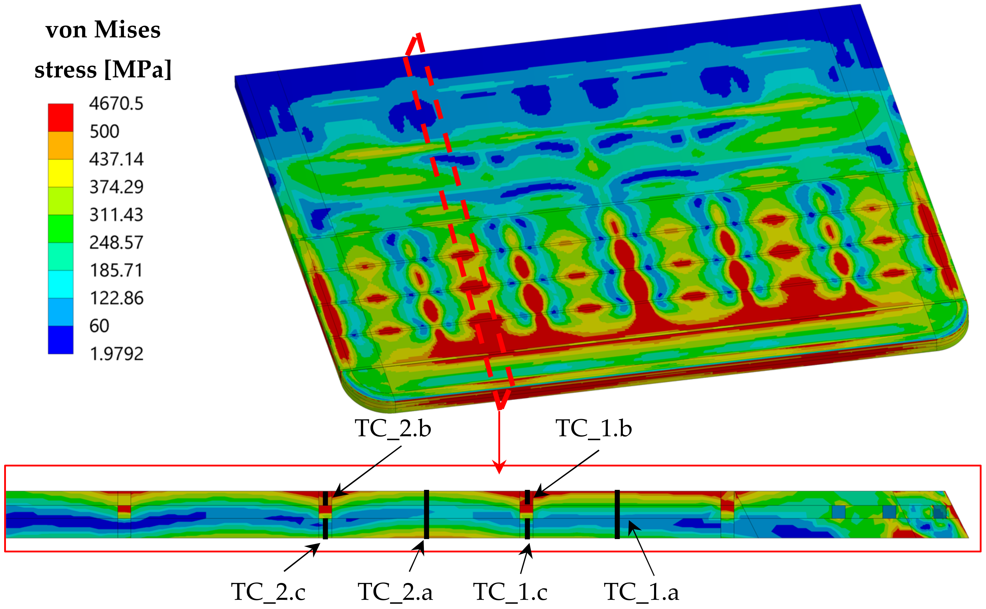
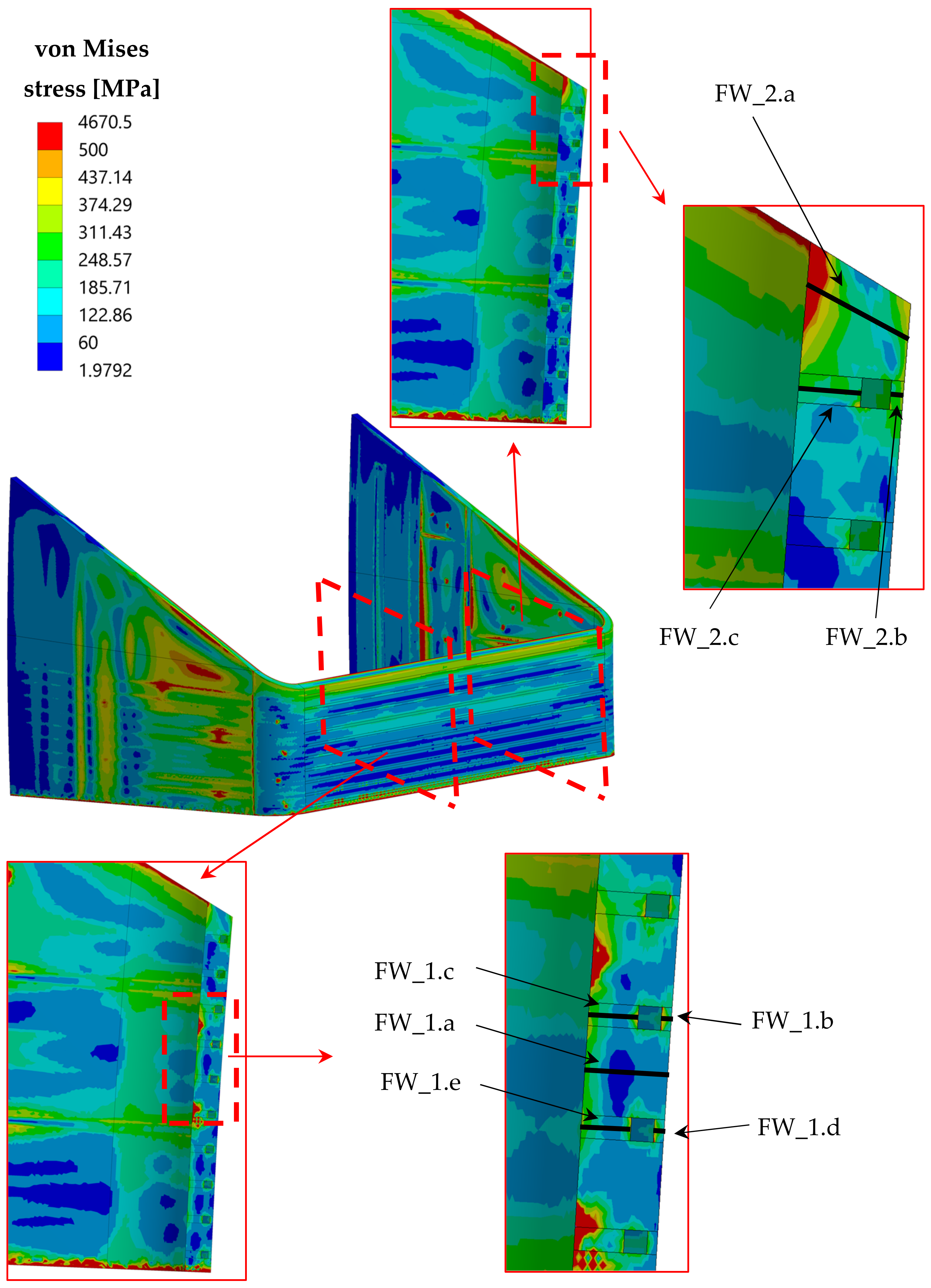
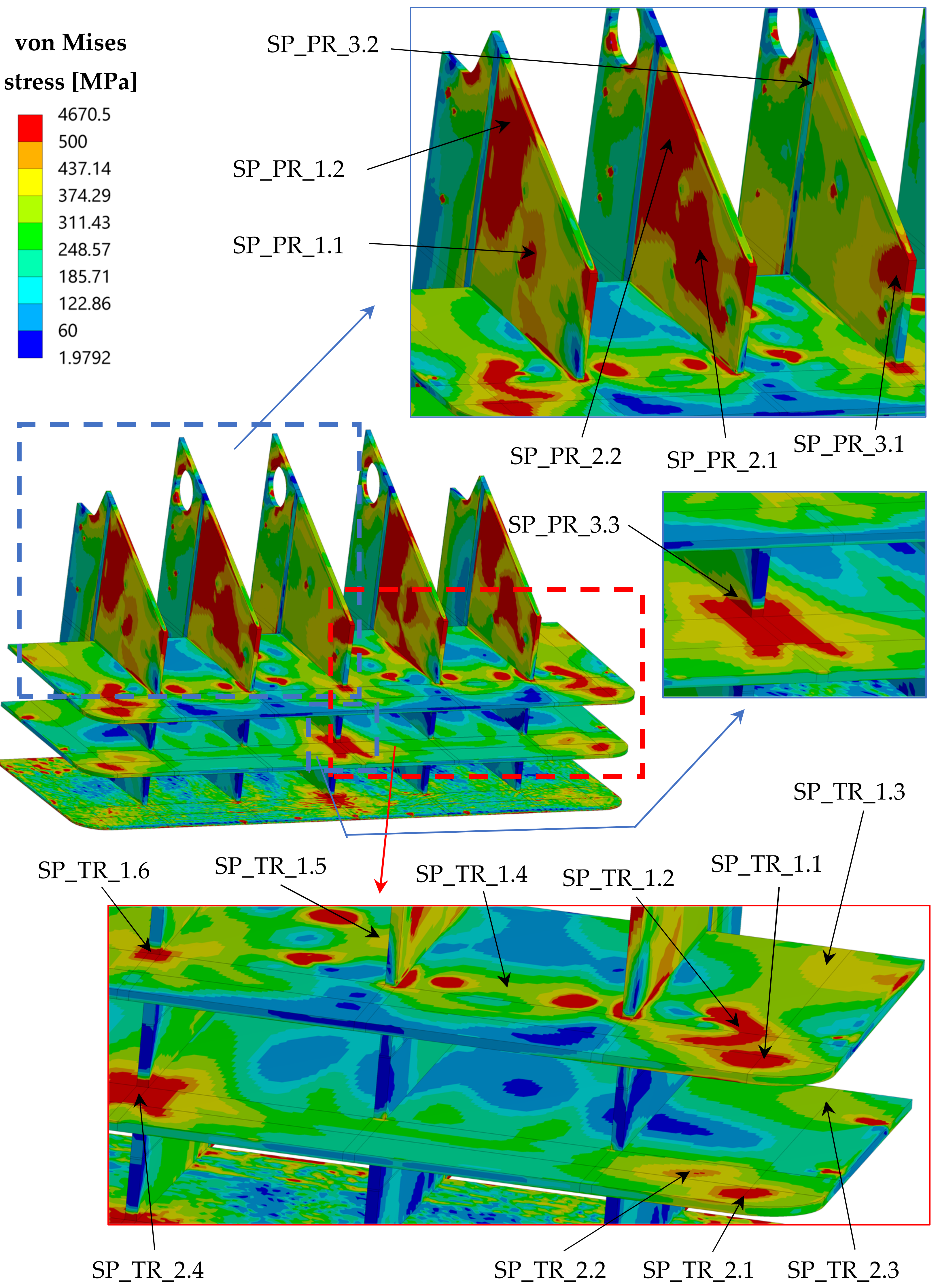
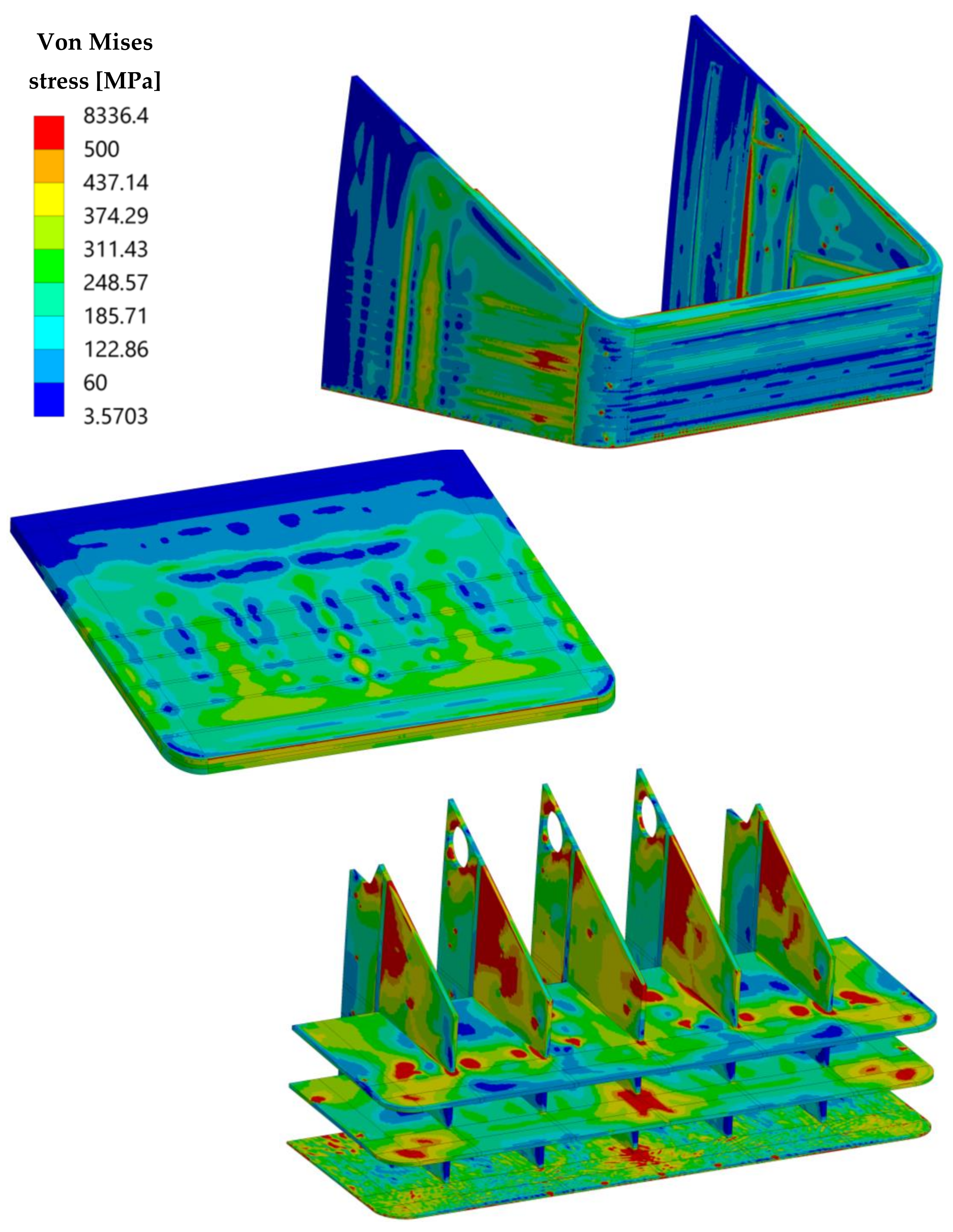
Figure 10, the von Mises equivalent stress field calculated within TC, FW-SWs and SPs domains under OP loading conditions are depicted, respectively, with the indication of the path locations.
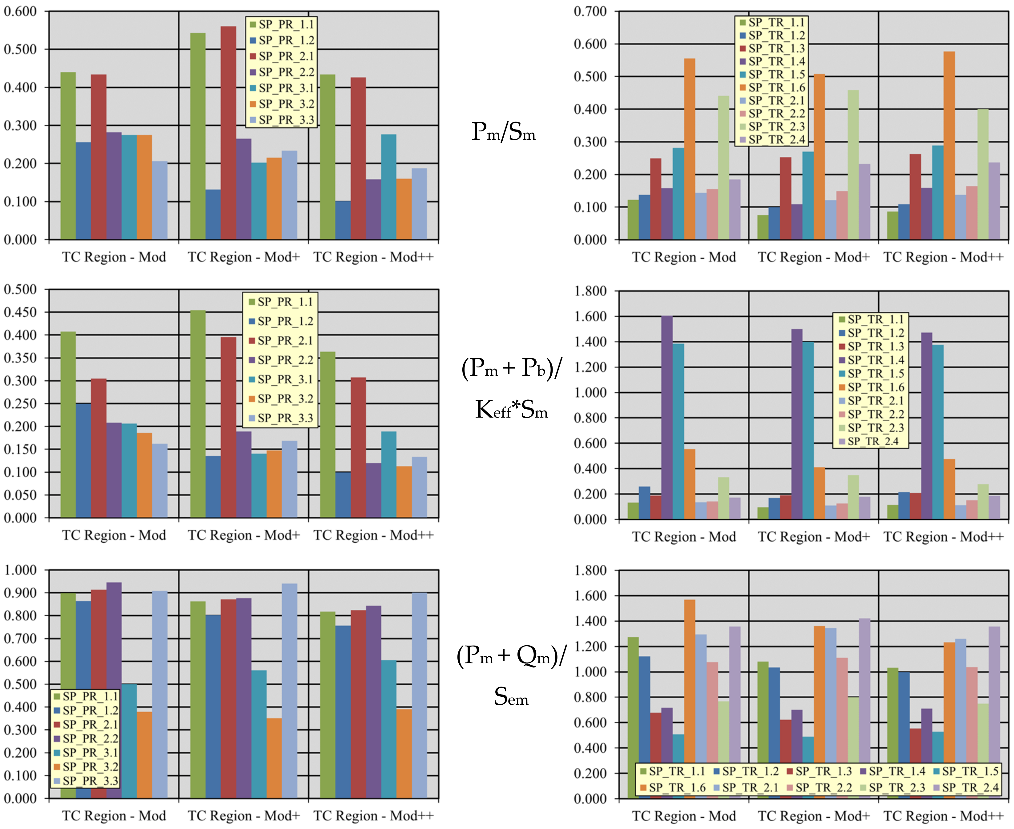
It has to be observed that, as for SPs, the paths are oriented through the plate thickness for both horizontal (toroidal–radial—TR) and vertical (polodial–radial—PR) SPs. Looking at the von Mises equivalent stress spatial distributions, it can be observed that some hotspots (i.e., isolated red stains in the distributions) are visible, mainly originated by the action of ferromagnetic forces which are applied as concentrated forces in the model. Hence, in close proximity to these stains, no significant evaluation in terms of RCC-MRx code application is possible. Moreover, it can be clearly observed that most of the assessed domain experiences von Mises stress values lower than 500 MPa, which is usually an index of promising structural behavior. The worst situation seems to be predicted for the SPsv in the TC slice, since values greater than 500 MPa are calculated in a large volume. Once the proper paths are selected, a stress linearization procedure is performed in order to compare the equivalent stress values to the stress limits prescribed by the RCC-MRx code, using the Level D criteria, as the OP scenario represents an accidental condition. In particular, four criteria are taken into account for the structural evaluation: immediate excessive deformation (IED, Pm/Sm), immediate plastic instability (IPI, (Pm + Pb)/(Keff × Sm)), immediate plastic flow localization (IPFL, (Pm + Qm)/Sem) and immediate fracture due to exhaustion of ductility (IF, (Pm + Pb + Q + F)/Set). While the first two criteria only consider the primary stresses (membrane, Pm, and bending, Pb), the others take into account also secondary stresses (membrane, Qm, and total, Q) and peak stress (F) occurring along the analyzed path. For each criterion, the stress limit values (Sm, Sem, Set, depending on the considered criterion) are calculated, for the service level D, to which the OP loading scenario relates, in accordance with the structural material and the average path temperature.
The obtained results are summarized within Table 1, Table 2 and Table 3 regarding criteria verification for paths located within the TC, FW-SWs and SPs respectively. In these tables, the ratios between the equivalent stress intensities and the corresponding stress limits are reported, as prescribed by the code. Hence, values greater than 1.0 (highlighted in red, when they arise) mean that the criterion is not fulfilled in that path. Moreover, values very close to the critical one (>0.9) are reported in orange to indicate the stress level closeness to the limit.
Concerning TC, the failures in the criteria verification are due to both primary and secondary stress. This means that a design review of the TC is needed, both in terms of geometry (i.e., thickness) and a cooling scheme to reduce the internal thermal gradients responsible for the secondary stress. Instead, very good behavior is carried out for the FW-SWs complex, suggesting its soundness under OP conditions. Lastly, a particularly critical situation is predicted for the SPs, especially for the SPsv (namely the PR ones) which are not able to withstand OP loading conditions both in terms of primary and secondary stress. Hence, these results suggest that a general review should be performed for the architecture of the whole TC slice.
Since the results obtained have shown that the prescribed RCC-MRx Level D criteria are not fulfilled, results in NO are not here reported for the sake of brevity. Additionally, under NO loading conditions, some paths do not verify criteria, especially within TC and SPs. Hence, an additional set of design modifications is necessary to improve the TC region thermo-mechanical performance.

3.2. The Second Update of the TC Region Design

In order to attain a geometric configuration able to withstand the thermo-mechanical loads in compliance with the RCC-MRx criteria, the “TC region-mod+” geometric layout is conceived. Its thermal and thermo-mechanical performance is assessed under both NO and OP steady-state loading scenarios, comparing the results with the pertinent design criteria and requirements.

3.2.1. “TC Region-Mod+” Geometric Configuration

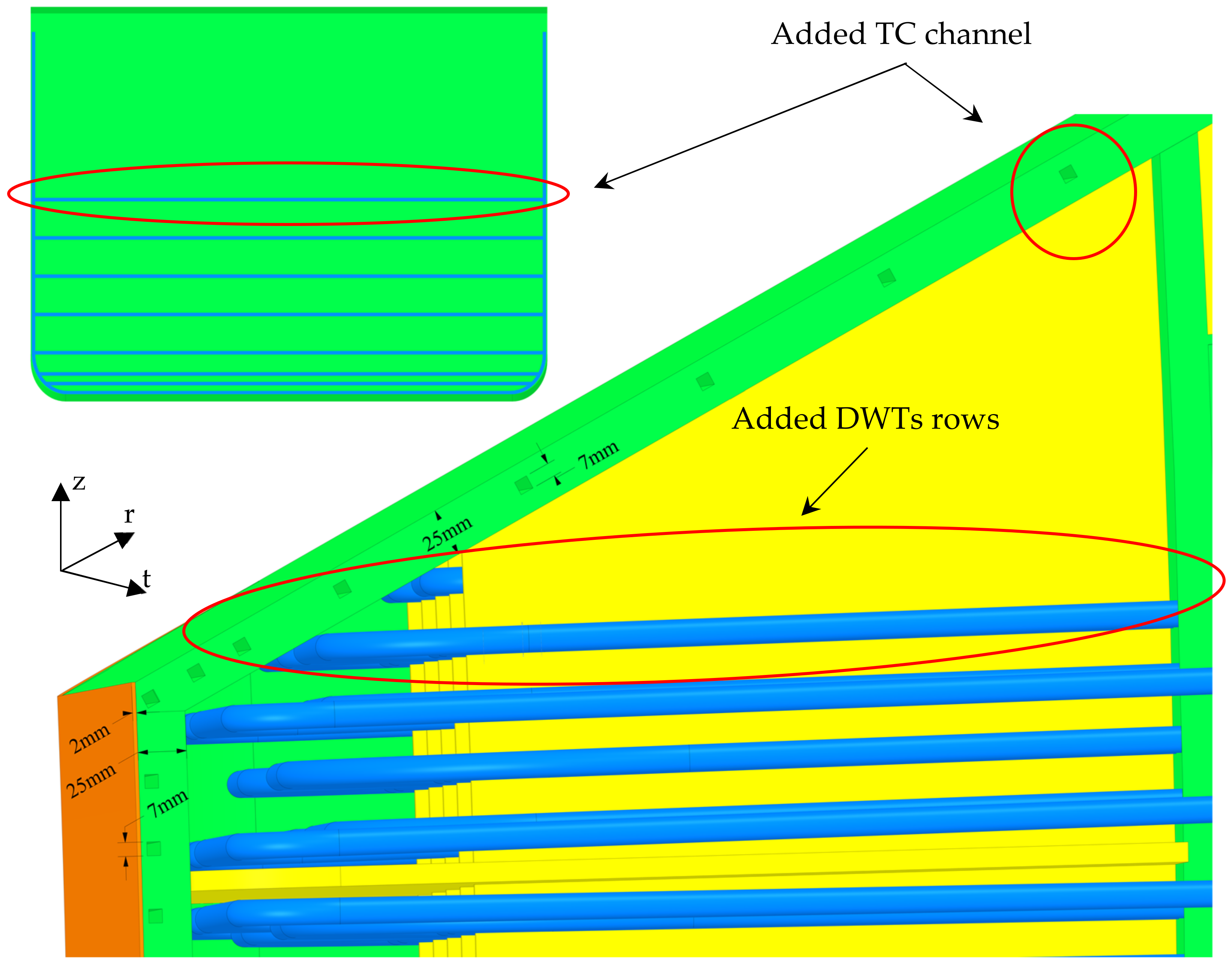
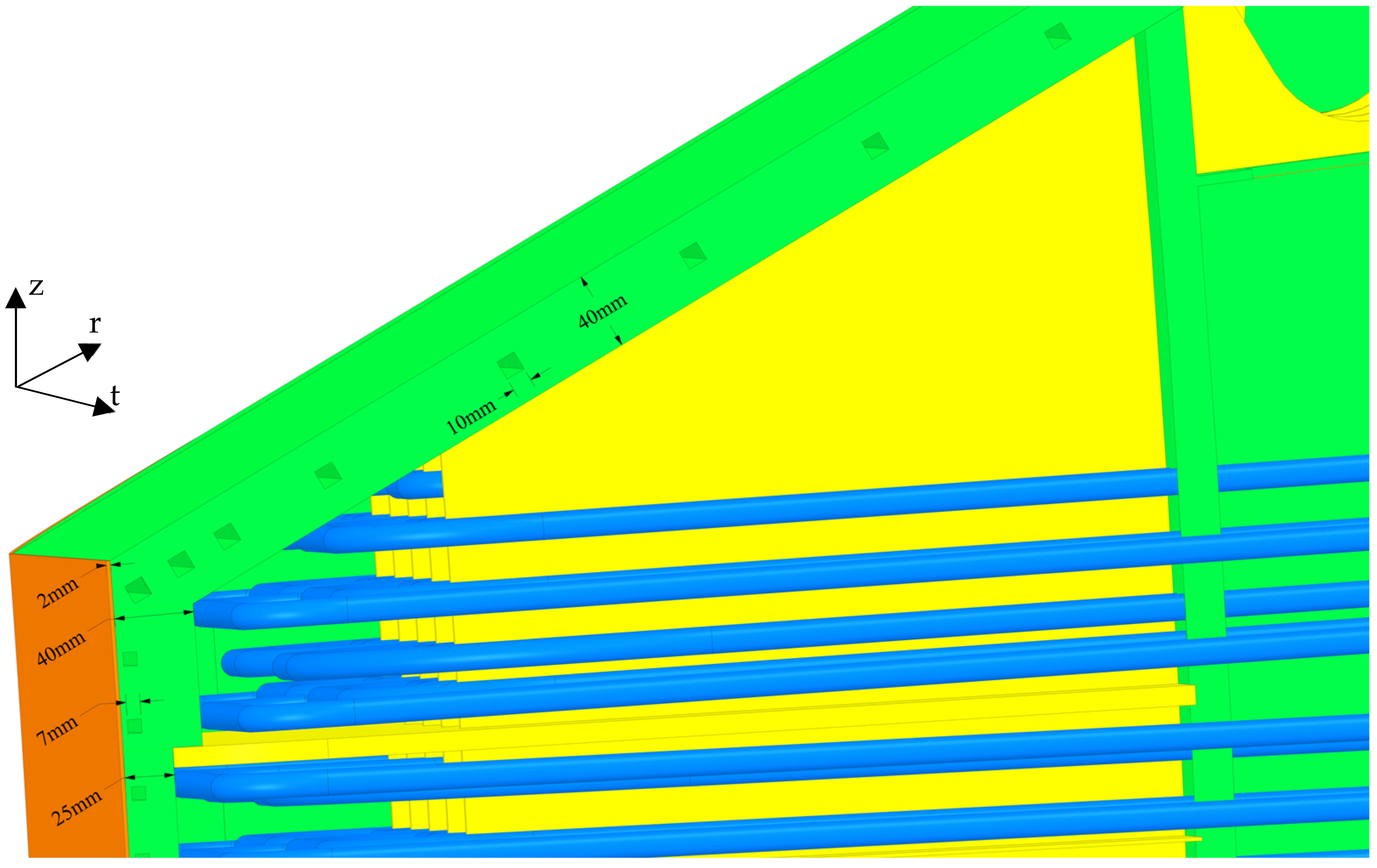
The “TC region-mod+” geometric configuration is derived from the previous “TC region-mod” layout, increasing the TC thickness from 25 mm to 40 mm, as well as enlarging the FW-SWs thickness in the slice housing the TC to 40 mm. In addition, the eight TC cooling channels are moved so as to be placed in the middle of the TC thickness, and their cross section is enlarged from 7 × 7 mm to 10 × 10 mm, as shown in Figure 11.

3.2.2. “TC Region-Mod+” Thermo-Mechanical Analysis and Results

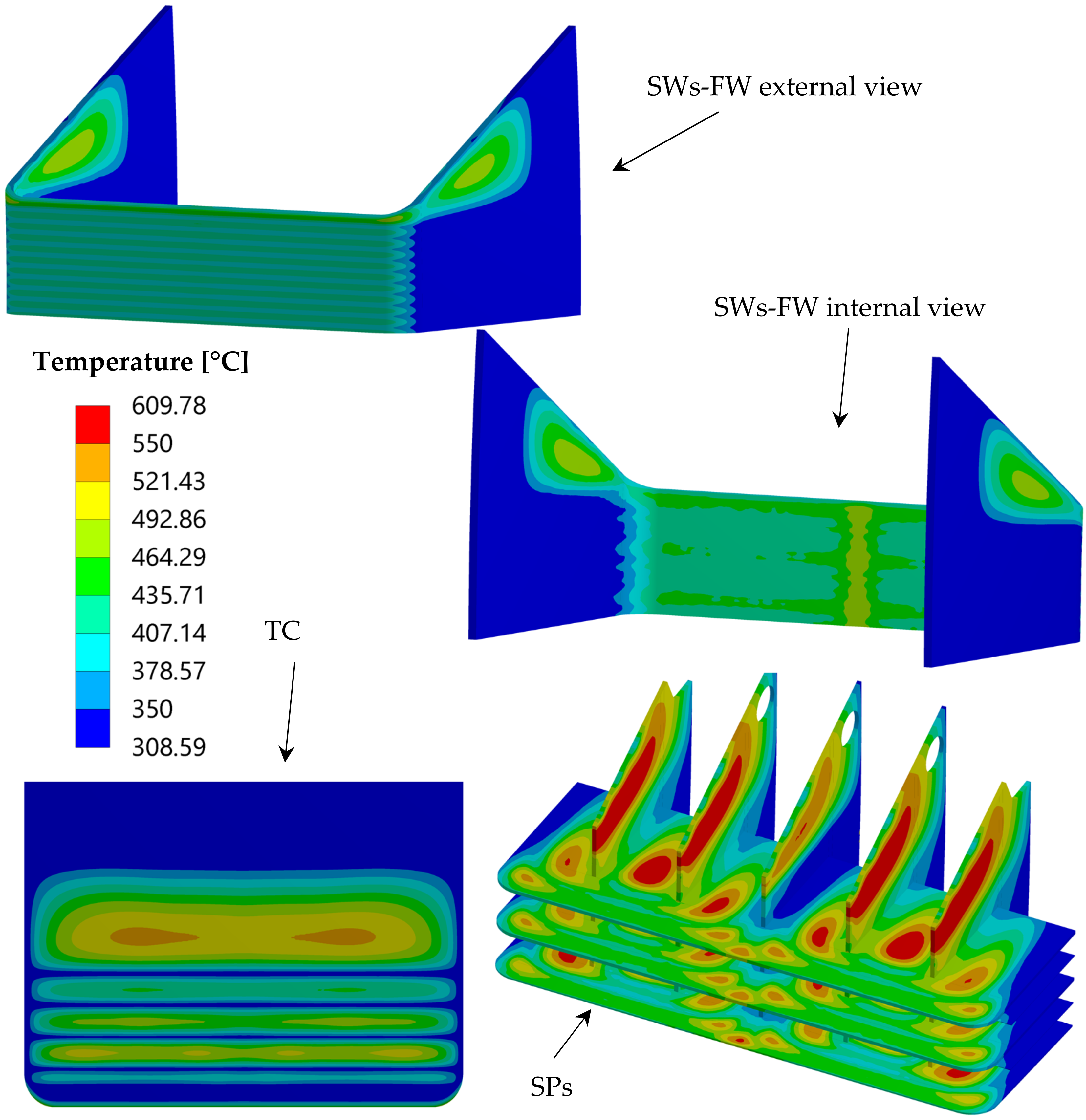
Once the “TC region-mod+” configuration is set up, a pertinent 3D FEM model is developed, and its thermal performance under the nominal loading conditions are assessed. The thermal results, here not reported for the sake of brevity, are qualitatively analogous to those obtained for the “TC region-mod” configuration, indicating a substantial fulfilment of the requirement on the suggested temperature limit. In particular, the maximum temperature predicted within FW is equal to 531.6 °C, which is higher than the previous cases (because of the FW thickness increase in the TC slice) but below the limit. As for TC, a maximum temperature of 472 °C is predicted, whereas no significant variations can be observed in the SPs temperature spatial distribution.
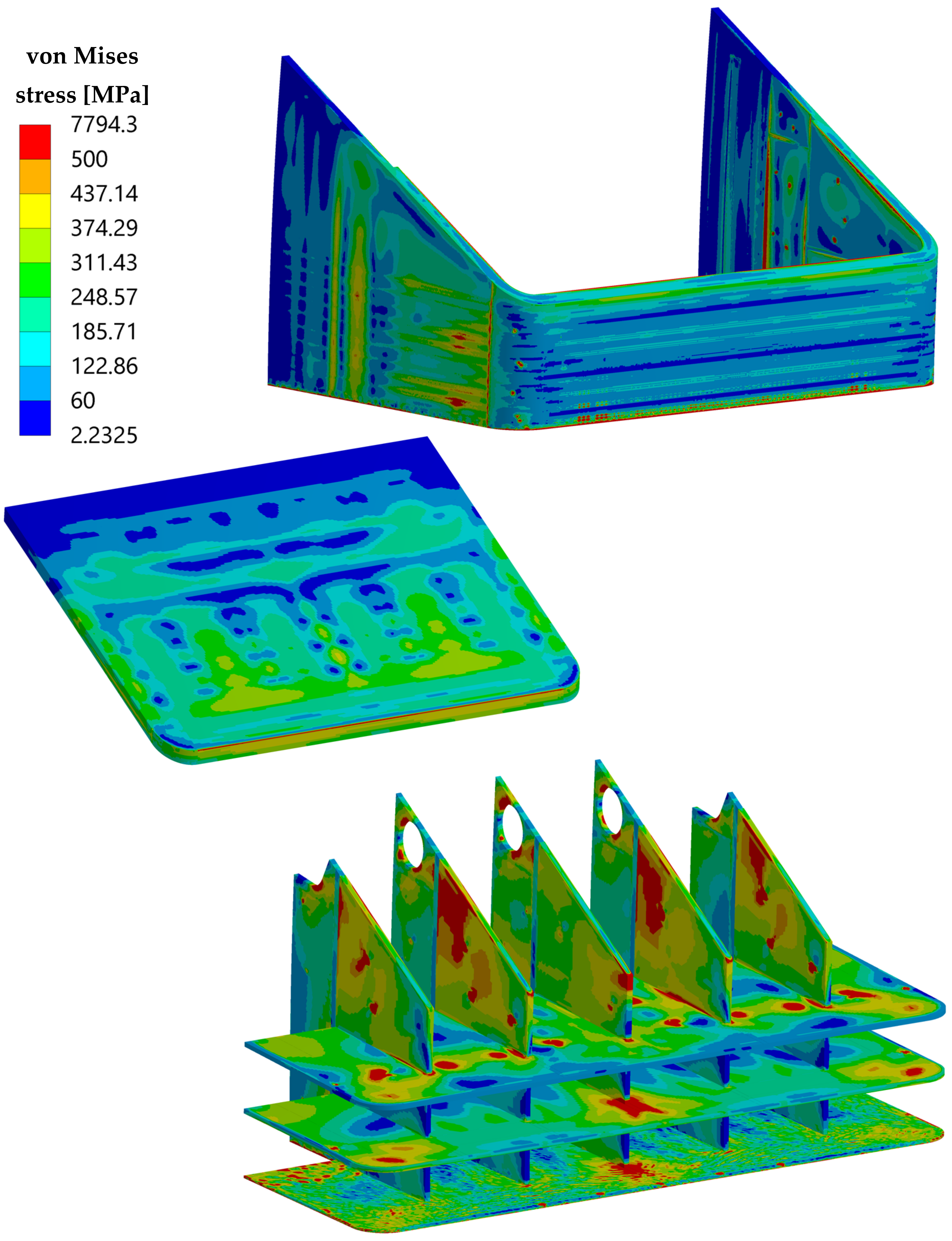
Therefore, thermo-mechanical analysis under NO and OP steady state loading scenarios is performed, and the verification of the RCC-MRx Level A and Level D criteria is performed on the same set of paths set up for the “TC region-mod” configuration. The 3D von Mises equivalent stress field calculated for the OP scenario is reported in Figure 12. Comparing these results with those shown obtained for the “TC region-mod” configuration, the improvement of the thermo-mechanical performance of the TC is clearly visible. In particular, almost all the TC geometric domain experiences von Mises stress values lower than 500 MPa.
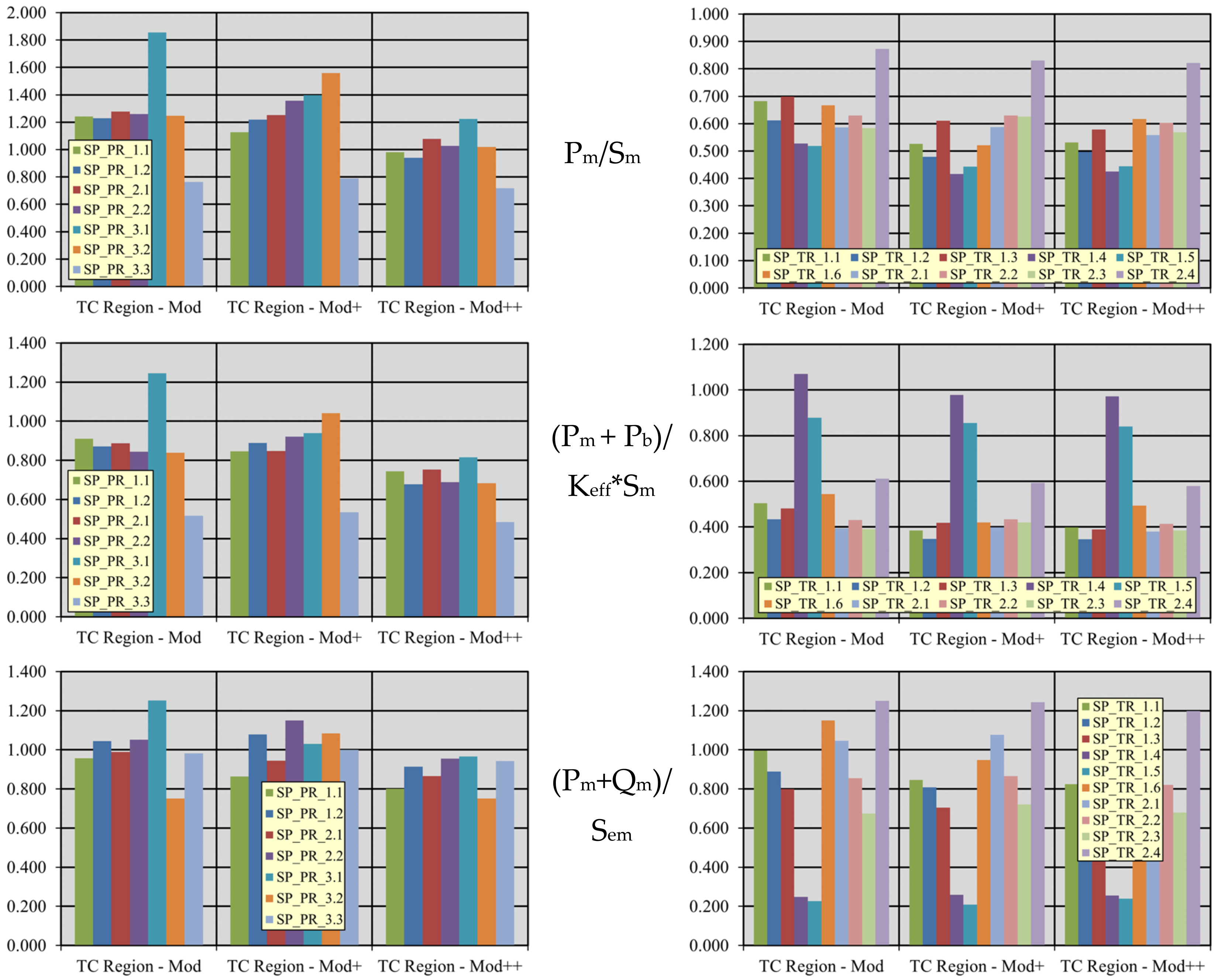
Then, in Table 4, Table 5 and Table 6, the results of the RCC-MRx Level D criteria verification are reported. As it can be observed, the considered criteria are completely fulfilled within the TC and FW-SWs domains, whereas there are still paths not satisfying them within the SPs, even with a reduced margin in comparison with the “TC region-mod” configuration. This means that the adopted geometric modifications allow significantly improving the TC structural performance, as well as having a certain impact on the SPs.
The predicted outcomes have shown a significant improvement of the TC region structural performance in terms of RCC-MRx criteria fulfilment both in OP and NO scenarios. Since the Level D criteria are not globally satisfied, the results obtained in NO are not reported for the sake of brevity, and an additional set of design improvements is brought about in order to intervene on the most critical regions highlighted by the performed analyses.

3.3. The Third Update of the TC Region Design

In order to attain a geometric configuration able to safely withstand the thermo-mechanical loads in compliance with the RCC-MRx criteria, the “TC region-mod++” geometric layout is conceived. Its thermal and thermo-mechanical performance is assessed under both NO and OP steady-state loading scenarios, comparing the results with the pertinent design criteria and requirements.

3.3.1. “TC Region-Mod++” Geometric Configuration

The “TC region-mod++” geometric configuration is derived from the previous “TC region-mod+” layout, increasing the FW thickness, in the slice adjacent to the TC region, from 25 to 32.5 mm. The latter modification is necessary to progressively reduce the thickness difference between FWs of the poloidally adjacent slides, providing the first SPh with more robust support to withstand the loads applied within the slice housing the TC. Moreover, the SPsv thickness in the slice housing the TC is increased from the nominal value of 12 mm to 14 mm, as shown in Figure 13.

3.3.2. “TC Region-Mod++” Thermo-Mechanical Analysis and Results

Once the “TC region-mod++” configuration is set up, its thermal performance under the nominal loading conditions is assessed. The thermal results, here not reported for the sake of brevity, still indicate a substantial fulfilment of the requirement on the suggested temperature limit. No significant variation in the maximum temperatures is obtained.
Therefore, thermo-mechanical analysis under NO and OP steady-state loading scenarios is performed, and the verification of the RCC-MRx Level A and Level D criteria is carried out on the same set of paths considered so far.
The obtained 3D spatial distributions of the von Mises equivalent stress field under the OP scenario are reported in Figure 14. Comparing these results with those shown obtained for the ”TC region-mod+” configuration, a sensible improvement of the SPs thermo-mechanical performance can be observed.
Moreover, in Table 7, Table 8 and Table 9, the results of the RCC-MRx Level D criteria verification are reported. It can be seen that TC and FW-SWs fully match the criteria, whereas for SPs, some criteria are not satisfied along some paths, even with a narrow margin and better global performance than the previous configurations. Then, looking at Table 10, Table 11 and Table 12, it can be observed that the RCC-MRx Level A criteria, namely those related to the NO scenario results, are totally fulfilled within TC, FW-SWs and SPsv. Nevertheless, criticalities are still present in SPsh, where some paths do not verify the criterion against the IPI and that against the IPFL. These results seem to suggest the necessity of further updating the TC region design, increasing also the thickness of the horizontal SP. Such a design modification is not addressed in the present work, and it could be matter of a follow-up research activity. In any case, the proposed “TC region-mod++” geometric configuration is robust enough to be integrated in the first version of the WCLL COB conceptual design. Indeed, the design solutions found for the TC and the FW-SWs allow fulfilling, for these components, all the design requirements both in the case of nominal and accidental configurations. Moreover, a promising solution is found also for the SPs, even if their design will affect the overall segment geometric configuration; for this reason, it should be further investigated in the next phases. Lastly, the soundness against accidental electro-magnetic loads must be proved in the following design iterations, but at the moment, the found geometric layout can be considered worthy to be integrated in the segment’s geometric layout.

4. Results Comparison and Discussion

In order to further discuss the trend of the obtained results and confirming that the followed design update strategy is leading to the definition of a sound design for the TC region of the WCLL COB segment, the following Figure 15 and Figure 16, showing a compact view of the design criteria verification carried out in for the “TC region-mod”, “TC region-mod+” and “TC region-mod++” configurations, are reported. In particular, attention is paid to the criteria against the IED (Pm/Sm), the IPI ((Pm + Pb)/Keff × Sm) and the IPFL ((Pm + Qm)/Sem) since they are not totally fulfilled within SPs in both NO and OP analyses.
Looking at the pictures, it can be noted that, for a given criterion and for a given path, the ratio obtained from the “TC region-mod++” analysis is lower than, or, at maximum, equal to, the analogous value obtained from “TC region-mod” analysis. This simple observation allows demonstrating that the followed design improvement strategy is promising, and it is worthy to be pursued as a follow up of the research activity herein presented.

5. Conclusions

Within the framework of EUROfusion activities, an intense research campaign is ongoing to attain a robust design for the WCLL COB segment. In this context, the TC region is being designed so as to allow the fulfilment of the thermal and mechanical design requirements. Starting from the reference geometric configuration, several iterations have been performed to improve the thermal and structural performances of the TC region, investigating its response under the NO and OP steady state loading scenarios and comparing the obtained results with the design requirements and the reference RCC-MRx structural design criteria. The found “TC region-mod++” configuration is equipped with a TC and a FW-SWs complex able to fully withstand the prescribed requirements, whereas the SPs grid needs to be further revised and improved. To this end, the method followed and described in this paper seems to be the most appropriate to attain a sound design solution also for SPs. Further analysis of additional design modifications and more refined modeling assumptions are necessary to continue this activity. In any case, the found design solution for the TC region can be considered a design improvement to be integrated in the first version of the geometric layout of the WCLL COB segment developed in the frame of the DEMO conceptual design phase. Hence, the results here presented represent a milestone in the development of the WCLL BB conceptual design. On the basis of the found geometric configuration, further design iterations could prove the soundness of the “TC region mod++” geometric configuration against accidental electro-magnetic loads, as well as further refining the design so as to allow the design criteria fulfilment also within SPs.

Author Contributions

Conceptualization, P.A.D.M., S.G., G.B., I.C. and P.A.; methodology, P.A.D.M., S.G., G.B., I.C. and P.A.; formal analysis, P.A.D.M., S.G., G.B., I.C. and P.A.; investigation, S.G., G.B. and I.C.; resources, S.G., G.B. and I.C.; data curation, S.G., G.B. and I.C.; writing—original draft preparation, P.A.D.M., S.G., G.B., I.C. and P.A.; writing—review and editing, P.A.D.M., S.G., G.B., I.C. and P.A.; visualization, P.A.D.M., S.G., G.B., I.C. and P.A.; supervision, P.A.D.M.; project administration, P.A.D.M.; funding acquisition, P.A.D.M. All authors have read and agreed to the published version of the manuscript.

Funding

This work has been carried out within the framework of the EUROfusion Consortium and has received funding from the Euratom research and training program 2014 to 2018 and 2019 to 2020 under grant agreement No. 633053. The views and opinions expressed herein do not necessarily reflect those of the European Commission.

Data Availability Statement

Data available on request from the authors.

Conflicts of Interest

The authors declare no conflict of interest.

References

  1. Donné, A.J.H. European Research Roadmap to the Realisation of Fusion Energy; EUROfusion: Garching, Germany, 2018; ISBN 978-3-00-061152-0. [Google Scholar]
  2. Cismondi, F.; Spagnuolo, G.A.; Boccaccini, L.V.; Chiovaro, P.; Ciattaglia, S.; Cristescu, I.; Day, C.; Del Nevo, A.; Di Maio, P.A.; Federici, G.; et al. Progress of the conceptual design of the European DEMO breeding blanket, tritium extraction and coolant purification systems. Fusion Eng. Des. 2020, 157, 111640. [Google Scholar] [CrossRef] [Green Version]
  3. Federici, G.; Boccaccini, L.; Cismondi, F.; Gasparotto, M.; Poitevin, Y.; Ricapito, I. An overview of the EU breeding blanket design strategy as an integral part of the DEMO design effort. Fusion Eng. Des. 2019, 141, 30–42. [Google Scholar] [CrossRef]
  4. Arena, P.; Del Nevo, A.; Moro, F.; Noce, S.; Mozzillo, R.; Imbriani, V.; Giannetti, F.; Edemetti, F.; Froio, A.; Savoldi, L.; et al. The DEMO Water-Cooled Lead-Lithium Breeding Blanket: Design status at the end of the Pre-Conceptual Design Phase. Appl. Sci. 2021, 11, 11592. [Google Scholar] [CrossRef]
  5. Spagnuolo, G.A.; Arrendondo, R.; Boccaccini, L.V.; Chiovaro, P.; Ciattaglia, S.; Cismondi, F.; Coleman, M.; Cristescu, I.; D’Amico, S.; Day, C.; et al. Integrated design of breeding blanket and ancillary systems related to the use of helium or water as a coolant and impact on the overall plant design. Fus. Eng. Des. 2021, 173, 112933. [Google Scholar] [CrossRef]
  6. RCC-MRx. Design and Construction Rules for Mechanical Components of Nuclear Installations; AFCEN: Courbevoie, France, 2013.
  7. Del Nevo, A.; Arena, P.; Caruso, G.; Chiovaro, P.; Di Maio, P.A.; Eboli, M.; Edemetti, F.; Forgione, N.; Forte, R.; Froio, A.; et al. Recent progress in developing a feasible and integrated conceptual design of the WCLL BB in EUROfusion project. Fusion Eng. Des. 2019, 146, 1805–1809. [Google Scholar] [CrossRef] [Green Version]
  8. Catanzaro, I.; Arena, P.; Basile, S.; Bongiovi, G.; Chiovaro, P.; Del Nevo, A.; Di Maio, P.A.; Forte, R.; Maione, I.A.; Vallone, E. Structural assessment of the EU DEMO WCLL Central Outboard Blanket segment under normal and off-normal operating conditions. Fusion Eng. Des. 2021, 167, 112350. [Google Scholar] [CrossRef]
  9. Forte, R.; Arena, P.; Bongiovì, G.; Catanzaro, I.; Del Nevo, A.; Di Maio, P.A.; Tomarchio, E.; Vallone, E. Preliminary design of the top cap of DEMO Water-Cooled Lithium Lead breeding blanket segments. Fusion Eng. Des. 2020, 161, 111884. [Google Scholar] [CrossRef]
  10. Edemetti, F.; Di Piazza, I.; Del Nevo, A.; Caruso, G. Thermal-hydraulic analysis of the DEMO WCLL elementary cell: BZ tubes layout optimization. Fusion Eng. Des. 2020, 160, 111956. [Google Scholar] [CrossRef]
  11. Moro, F.; Arena, P.; Catanzaro, I.; Colangeli, A.; Del Nevo, A.; Flammini, D.; Fonnesu, N.; Forte, R.; Imbriani, V.; Mariano, G.; et al. Nuclear performances of the water-cooled lithium lead DEMO reactor: Neutronic analysis on a fully heterogeneous model. Fusion Eng. Des. 2021, 168, 112514. [Google Scholar] [CrossRef]
  12. Maviglia, F.; Vizvary, Z.; Richiusa, M.L.; Gerardin, J.; Firdaouss, M. DEMO PFC Surface Heat Load Specifications, EFDA IDM Ref. EFDA_D_2P985Q. 2020. [Google Scholar]
  13. Berry, T.; Eade, T. Activation analysis and evaluation of inventories, decay heat, for important components—Activity 2019—CCFE contribution (Calculation of decay heat in PbLi for entire WCLL reactor), EFDA IDM Ref. EFDA_D_2NQL5P.
  14. Di Maio, P.A.; Arena, P.; Bongiovi, G.; Chiovaro, P.; Del Nevo, A.; Richiusa, M.L. On the numerical assessment of the thermo-mechanical behaviour of the DEMO Water Cooled Lithium Lead equatorial outboard blanket module. Fusion Eng. Des. 2017, 124, 725–729. [Google Scholar] [CrossRef]
  15. Spagnuolo, G.A.; Boccaccini, L.V.; Bongiovi, G.; Cismondi, F.; Maione, I.A. Development of load specifications for the design of the breeding blanket system. Fusion Eng. Des. 2020, 157, 111657. [Google Scholar] [CrossRef] [Green Version]
  16. Gaganidze, E. Material Properties Handbook—EUROFER97, EFDA IDM Ref. EFDA_D_2NZHBS. 2020. Available online: http://idm.euro-fusion.org/?uid=2NZHBS (accessed on 20 November 2021).
  17. Martelli, D.; Venturini, A.; Utili, M. Literature review of lead-lithium thermophysical properties. Fusion Eng. Des. 2018, 138, 183–195. [Google Scholar] [CrossRef]
  18. Gaganidze, E.; Schoofs, F. Material Properties Handbook—Tungsten, EFDA IDM Ref. EFDA_D_2P3SPL. 2020. [Google Scholar]
  19. Maione, I.A.; Roccella, M.; Marin, A.; Bertolini, C.; Lucca, F. Analysis of EM loads on DEMO WCLL Breeding Blanket during VDE-up. Fusion Eng. Des. 2018, 136, 1523–1528. [Google Scholar] [CrossRef] [Green Version]
  20. Maione, I.A.; Roccella, M.; Lucca, F.; Villone, F.; Hernandez, F.; Del Nevo, A.; Bachmann, C. Electromagnetic analysis activities in support of the Breeding Blanket during the DEMO Pre-Conceptual Design Phase: Methodology and main results. Fus. Eng. Des. 2021, 166, 112285. [Google Scholar] [CrossRef]
  21. Catanzaro, I.; Bongiovì, G.; Di Maio, P.A. Analysis of the thermo-mechanical behaviour of the EU DEMO Water-Cooled Lithium Lead Central Outboard Blanket Segment under an optimized thermal field. Appl. Sci. 2022, 12, 1356. [Google Scholar] [CrossRef]
Figure 1. The top cap region reference geometric configuration.
Applsci 12 01564 g001
Figure 2. The 3D FEM model of the TC region plus adjacent slices—details of the mesh.
Applsci 12 01564 g002
Figure 3. TC reference configuration—temperature spatial distribution within Eurofer.
Applsci 12 01564 g003
Figure 4. The top cap region-mod geometric configuration.
Applsci 12 01564 g004
Figure 5. TC region-mod configuration—temperature spatial distribution within Eurofer.
Applsci 12 01564 g005
Figure 6. Temperature overtaking 550 °C within SPs domain.
Applsci 12 01564 g006
Figure 7. Displacement field applied onto the model lower surface in NO analysis.
Applsci 12 01564 g007
Figure 8. OP von Mises equivalent stress field and path locations within TC domain.
Applsci 12 01564 g008
Figure 9. OP von Mises equivalent stress field and path locations within FW-SWs domain.
Applsci 12 01564 g009
Figure 10. OP von Mises equivalent stress field and path locations within SPs domain.
Applsci 12 01564 g010
Figure 11. The “TC region-mod+” geometric configuration.
Applsci 12 01564 g011
Figure 12. OP von Mises equivalent stress fields within the “TC region-mod+” geometric configuration.
Applsci 12 01564 g012
Figure 13. The “TC region-mod++” geometric configuration.
Applsci 12 01564 g013
Figure 14. OP von Mises equivalent stress fields within the “TC region-mod++” geometric configuration.
Applsci 12 01564 g014
Figure 15. Trends of Level A criteria verification for SPs.
Applsci 12 01564 g015
Figure 16. Trends of Level D criteria verification for SPs.
Applsci 12 01564 g016
Table 1. RCC-MRx Level D criteria verification within TC domain.
PathPm/Sm(Pm + Pb)/(Keff × Sm)(Pm + Qm)/Sem(Pm + Pb + Q + F)/Set
TC_1. a0.2690.8760.3070.246
TC_1. b1.0130.8591.0470.333
TC_1. c0.5040.6440.2850.203
TC_2. a0.2610.9850.2780.179
TC_2. b0.9870.8591.0110.336
TC_2. c0.4780.6300.2260.192
Table 2. RCC-MRx Level D criteria verification within FW-SWs domain.
PathPm/Sm(Pm + Pb)/(Keff × Sm)(Pm + Qm)/Sem(Pm + Pb + Q + F)/Set
FW_1. a0.3090.3400.0400.097
FW_1. b0.8840.6320.7060.222
FW_1. c0.4140.5900.2070.251
FW_1. d0.7910.5710.6190.205
FW_1. e0.3860.4450.2170.150
FW_2. a0.4760.8580.3220.180
FW_2. b0.1810.2340.5160.185
FW_2. c0.6980.6420.4300.121
Table 3. RCC-MRx Level D criteria verification within SPs domain.
PathPm/Sm(Pm + Pb)/(Keff × Sm)(Pm + Qm)/Sem(Pm + Pb + Q + F)/Set
SP_PR_1.11.2430.9110.9580.149
SP_PR_1.21.2300.8711.0450.195
SP_PR_2.11.2770.8870.9880.146
SP_PR_2.21.2580.8441.0520.178
SP_PR_3.11.8551.2461.2520.209
SP_PR_3.21.2470.8380.7520.143
SP_PR_3.30.7640.5170.9810.268
SP_TR_1.10.6820.5050.9970.162
SP_TR_1.20.6120.4330.8880.158
SP_TR_1.30.6990.4820.8000.230
SP_TR_1.40.5271.0690.2480.095
SP_TR_1.50.5190.8780.2270.115
SP_TR_1.60.6670.5441.1490.295
SP_TR_2.10.5860.3941.0450.187
SP_TR_2.20.6290.4310.8540.154
SP_TR_2.30.5840.3910.6750.194
SP_TR_2.40.8730.6111.2510.281
Table 4. RCC-MRx Level D criteria verification within TC domain.
PathPm/Sm(Pm + Pb)/(Keff × Sm)(Pm + Qm)/Sem(Pm + Pb + Q + F)/Set
TC_1. a0.2120.4670.2510.160
TC_1. b0.5370.4350.6330.268
TC_1.c0.1810.2490.1100.155
TC_2. a0.2060.4820.2410.124
TC_2. b0.5010.4330.5970.234
TC_2.c0.2300.2680.1180.142
Table 5. RCC-MRx Level D criteria verification within FW-SWs domain.
PathPm/Sm(Pm + Pb)/(Keff × Sm)(Pm + Qm)/Sem(Pm + Pb+ Q + F)/Set
FW_1. a0.3540.2970.0430.090
FW_1. b0.7880.5760.6640.227
FW_1.c0.5380.6220.1710.256
FW_1. d0.7720.5660.6220.219
FW_1. e0.4360.4610.1810.146
FW_2. a0.3040.5950.2720.175
FW_2. b0.1950.2190.5790.197
FW_2.c0.4580.5000.3560.147
Table 6. RCC-MRx Level D criteria verification within SPs domain.
PathPm/Sm(Pm + Pb)/(Keff × Sm)(Pm + Qm)/Sem(Pm + Pb + Q + F)/Set
SP_PR_1.11.1260.8470.8640.139
SP_PR_1.21.2190.8881.0780.226
SP_PR_2.11.2510.8470.9450.139
SP_PR_2.21.3560.9211.1490.204
SP_PR_3.11.3980.9381.0300.173
SP_PR_3.21.5601.0421.0850.219
SP_PR_3.30.7900.5340.9990.267
SP_TR_1.10.5260.3850.8460.156
SP_TR_1.20.4800.3470.8090.159
SP_TR_1.30.6110.4180.7050.203
SP_TR_1.40.4160.9780.2590.101
SP_TR_1.50.4440.8550.2090.115
SP_TR_1.60.5210.4190.9470.251
SP_TR_2.10.5880.3991.0770.192
SP_TR_2.20.6300.4330.8660.150
SP_TR_2.30.6260.4190.7200.208
SP_TR_2.40.8300.5931.2430.276
Table 7. RCC-MRx Level D criteria verification within TC domain.
PathPm/Sm(Pm + Pb)/(Keff × Sm)(Pm + Qm)/Sem(Pm + Pb + Q + F)/Set
TC_1.a0.2050.4540.2550.156
TC_1.b0.5220.4240.6260.267
TC_1.c0.1760.2440.1090.153
TC_2.a0.1980.4710.2420.122
TC_2.b0.4890.4210.5900.234
TC_2.c0.2030.2530.1020.139
Table 8. RCC-MRx Level D criteria verification within FW-SWs domain.
PathPm/Sm(Pm + Pb)/(Keff × Sm)(Pm + Qm)/Sem(Pm + Pb + Q + F)/Set
FW_1.a0.3020.2600.0920.091
FW_1.b0.6660.4890.6780.236
FW_1.c0.4130.4590.1250.240
FW_1.d0.6800.5000.6330.226
FW_1.e0.3400.3770.1380.142
FW_2.a0.2970.5880.2680.157
FW_2.b0.2170.2050.5190.177
FW_2.c0.4480.5080.3370.128
Table 9. RCC-MRx Level D criteria verification within SPs domain.
PathPm/Sm(Pm + Pb)/(Keff × Sm)(Pm + Qm)/Sem(Pm + Pb + Q + F)/Set
SP_PR_1.10.9810.7440.8000.130
SP_PR_1.20.9410.6780.9140.190
SP_PR_2.11.0790.7530.8650.132
SP_PR_2.21.0270.6890.9560.170
SP_PR_3.11.2230.8150.9660.164
SP_PR_3.21.0200.6820.7500.156
SP_PR_3.30.7180.4850.9420.256
SP_TR_1.10.5320.3980.8250.161
SP_TR_1.20.4970.3460.7770.151
SP_TR_1.30.5780.3890.6910.202
SP_TR_1.40.4260.9710.2550.102
SP_TR_1.50.4440.8400.2390.119
SP_TR_1.60.6170.4940.9070.229
SP_TR_2.10.5590.3801.0220.182
SP_TR_2.20.6030.4130.8210.142
SP_TR_2.30.5690.3850.6800.196
SP_TR_2.40.8210.5801.1990.268
Table 10. RCC-MRx Level A criteria verification within TC domain.
PathPm/Sm(Pm + Pb)/(Keff × Sm)(Pm + Qm)/Sem(Pm + Pb + Q + F)/Set
TC_1.a0.0310.0420.2810.109
TC_1.b0.0880.1030.4820.239
TC_1.c0.0920.1030.0720.165
TC_2.a0.0280.0520.3480.105
TC_2.b0.1120.1200.4650.216
TC_2.c0.0950.1130.0390.150
Table 11. RCC-MRx Level A criteria verification within FW-SWs domain.
PathPm/Sm(Pm + Pb)/(Keff × Sm)(Pm + Qm)/Sem(Pm + Pb + Q + F)/Set
FW_1.a0.1750.1560.3090.167
FW_1.b0.2810.1930.5960.213
FW_1.c0.3040.3780.4270.328
FW_1.d0.1930.1480.4830.190
FW_1.e0.2550.1970.4310.176
FW_2.a0.0390.0480.2100.140
FW_2.b0.0960.0690.5730.168
FW_2.c0.0660.0620.2480.133
Table 12. RCC-MRx Level A criteria verification within SPs domain.
PathPm/Sm(Pm + Pb)/(Keff × Sm)(Pm + Qm)/Sem(Pm + Pb + Q + F)/Set
SP_PR_1.10.4340.3630.8170.135
SP_PR_1.20.1010.0990.7560.151
SP_PR_2.10.4260.3070.8240.126
SP_PR_2.20.1580.1200.8440.148
SP_PR_3.10.2770.1890.6060.104
SP_PR_3.20.1600.1130.3910.077
SP_PR_3.30.1880.1330.9000.211
SP_TR_1.10.0860.1151.0330.200
SP_TR_1.20.1090.2150.9970.182
SP_TR_1.30.2630.2080.5550.139
SP_TR_1.40.1591.4720.7090.219
SP_TR_1.50.2891.3750.5290.187
SP_TR_1.60.5770.4761.2330.273
SP_TR_2.10.1370.1131.2610.223
SP_TR_2.20.1640.1501.0360.178
SP_TR_2.30.4000.2780.7490.181
SP_TR_2.40.2370.1861.3560.276
Publisher’s Note: MDPI stays neutral with regard to jurisdictional claims in published maps and institutional affiliations.

