
Robotic Device for Out-of-Clinic Post-Stroke Hand Rehabilitation

Laboratory of Robotics, Faculty of Electrical Engineering, University of Ljubljana, Tržaška cesta 25, 1000 Ljubljana, Slovenia
*
Authors to whom correspondence should be addressed.
Appl. Sci. 2022, 12(3), 1092; https://doi.org/10.3390/app12031092
Submission received: 20 December 2021
/
Revised: 18 January 2022
/
Accepted: 19 January 2022
/
Published: 21 January 2022
(This article belongs to the Special Issue Robotic-Based Technologies for Rehabilitation and Assistance)
Abstract
:Due to the ageing population and an increasing number of stroke patients, we see the potential future of rehabilitation in telerehabilitation, which might alleviate the workload of physiotherapists and occupational therapists. In order to enable the use of telerehabilitation, devices aimed for home and independent use need to be developed. This paper describes the design of a robotic device for post-stroke wrist and finger rehabilitation and evaluates the movement it can perform. Six healthy subjects were tested in three experimental conditions: performing a coupled movement of wrist and fingers from flexion to extension without the device, with a passive device, and with an active device. The kinematics of the hand were captured using three Optotrak Certus motion capture systems and tracking 11 infrared active light-emitting diode (LED) markers. The results are presented in the form of base-line trajectories for all middle finger (MF) joints. In addition, the deviations of trajectories between conditions across all subjects were computed for the metacarpophalangeal (MCP) joint and fingertip of the MF and pinkie (PF) finger. Deviations from the base-line trajectory between measurement protocols and the root-mean-square deviation (RMSD) values indicate that the motion of the hand, imposed by the developed device, is comparable to the unconstrained motion of the healthy subjects, especially when moving into the extension, opening the hand.
1. Introduction
Stroke is one of the leading causes of death and disability among adults worldwide, with its relative incidence doubling every ten years after age 55 [1,2,3]. According to the World Health Organisation, the number of people aged 65 and over will increase by 207% until 2050 [2]; therefore, it is expected that the economic and health burden related to stroke will continue to rise.
The reduction or loss of functional abilities is one of the most common consequences of stroke. It can cause, among others, motor and movement impairments, such as loss of coordination, strength and skills, reduced ability of fractionated movement, abnormal muscle tone, and paresis [1,4,5,6,7].
Even though a stroke usually affects both extremities on one side of the body, regaining or improving the upper limb function is more problematic than for the lower limb. A decreased upper limb function occurs in 85% of stroke patients. At 3–6 months post-stroke or even upon completing the standard rehabilitation program, its function is still not sufficiently restored in 50–80% of the patients, further limiting their activities of daily living (ADL) [1,8,9,10,11,12]. Meanwhile, improvements in the lower limb function and regaining the ability to walk are expected in 75–83% of patients [8].
Particularly problematic in the recovery of upper limb function is spasticity—its prevalence varies between 4% and 46% in different post-stroke stages [6,13,14,15]; however, it is most common in the chronic stage [13].
Physiotherapy plays a vital role in the post-stroke rehabilitation process. It primarily aims to maintain joint mobility, prevent loss of strength and changes in muscle tone, and improve voluntary movement control [16]. There are various approaches to the rehabilitation of motor and functional abilities of the upper limb post-stroke; however, it has been shown that the implementation of protocols that include regular, high-intensity, task-specific exercises, and focus of high repeatability of the movement is one of the most effective approaches [4,17,18,19,20,21,22,23,24]. Exercises involving a prolonged stretch of the affected muscles should also be included to reduce spasticity [25,26]. Commonly deployed rehabilitation exercises for the wrist and hand are the flexion-extension of the fingers, grasping of different objects, and flexion-extension of the wrist while keeping the fingers extended [27].
Providing high-intensity and task-specific rehabilitation exercise protocols with highly repetitive movements can be, despite their effectiveness, difficult or sometimes even impossible to ensure for all patients. Namely, such protocols are physically exhausting and time consuming for the therapists, as they require manual interaction and one-on-one work with each patient every day for several weeks [17,28].
Thus, there is a trend of increased use of robotic devices in stroke rehabilitation protocols because not only can they reduce labour costs [29] and therapists’ physical exertion [30,31], but they can also provide customised, high-intensity, repeatable, and task-oriented interactive exercises and enable an objective and reliable monitoring of the patient’s progress [17,22,24,32].
Another great advantage of using robotic devices for rehabilitation is that they can accurately and systematically control the amount of force applied to the patient and gradually change the level of assistance or resistance, therefore adjusting the exercise intensity to the patient’s abilities [33]. Most robotic rehabilitation devices usually offer different training modalities: passive, assistive, active, and resistive [22,32]. The training modalities are classified as in other forms of conventional therapy and describe the patient’s activity level while interacting with the device [22].
Studies have shown that the use of robotic rehabilitation devices, when used for post-stroke rehabilitation of the upper limb, can:
However, many studies related to the post-stroke robotic rehabilitation of the upper limb primarily focus on the proximal arm joints, i.e., the shoulder and elbow, rather than the distal joints of the arm, i.e., the wrist and hand joints. The latter is interesting, as it has been found that therapeutic exercises for the distal arm joints can lead to functional improvements in both proximal and distal arm function [30,31,32]. Moreover, to improve the performance of ADL—reaching, gasping, manipulating, and carrying objects—the distal part of the arm must be included in the exercise protocol [22,40], as the functional improvements of the wrist and hand alone can significantly impact the functional improvement of the whole upper limb [41].
In addition to the frequent occurrence of spasticity, the problem of successful rehabilitation of the upper limb function may be that the onset of the distal arm joints’ movement recovery, compared to the proximal arm joints, usually occurs later. This delay means that even when patients regain strength and coordination in the shoulder and elbow joint, the function of the wrist and fingers is usually not yet restored, which further limits the ADL [42]. Patients especially wish to restore the ability of fine manipulation—writing, card playing, knob manipulation, and driving. Such manipulations require a coordinated action of several joints and muscles of the upper limb, particularly the wrist and hand joints [36].
Patients should continue to perform the therapeutic exercises even after discharge from the hospital. Lately, alongside robotic devices in rehabilitation, telerehabilitation technologies are also becoming increasingly used, especially in the neurological rehabilitation field. Compared to the traditional rehabilitation approaches, some of their most significant advantages are the reduced cost of the health care providers and enabling the patients to perform physiotherapy at home. The latter is especially beneficial for patients who have severe disabilities or live in rural areas and therefore could not as easily access the traditional rehabilitation services [43,44].
Given the fact that many hospitals and clinics discharge patients when they relearn how to walk—even if the function of the upper limb, especially its distal parts, has not yet been restored [9]—an appropriate rehabilitation device, designed for an out-of-clinic use, might help them to further recover the distal arm function. The device should provide therapeutic exercises for the wrist and fingers, such as flexion and extension of said joints. It should also have an adjustable level of assistance, motivate the patient by combining exercises with playing games during therapy and providing visual feedback, monitor therapy progress, enable independent use at home or in a nonclinical setting, and have relatively low manufacturing cost [33].
The state of the art shows multiple possible solutions regarding the design of such devices. Many patent records use wearable mechanical systems in the form of a glove or a soft splint covering the forearm, hand, or fingers. There are different moving segments, such as bars, pulleys, or belts, placed on the glove or splint alongside the hand and fingers. An actuator, usually placed on the forearm portion of the arm, moves the said segments back and forth, which results in the mobilisation of either one or more fingers or the wrist [45,46,47,48]. However, these devices seem difficult for donning and doffing—particularly in the case of spasticity or if the patients would try to use them independently. Devices, built in the form of exoskeletal mechanisms, such as [49,50,51], seem more suitable for independent use at home, regarding the complexity of the donning and doffing process. They use linear actuators or pneumatic muscles to actuate one or more degrees of freedom, which mobilises the wrist, fingers, or both.
However, none of the devices, covered in the state of the art, enable simultaneous movement of the wrist and fingers from flexion to extension with just one actuated degree of freedom (DOF). This article presents the design and verification of such a device, and it is organised as follows: after the Section 1—the introduction, the Section 2 describes the mechanical design of the device, its hardware components, and control scheme. It then describes the experimental protocol for measuring the similarity of hand movements with or without the device and the experimental setup used, followed by a description of data analysis. Section 3 presents the experimental results in the form of a visual comparison of hand trajectories in a sagittal view, graphs of deviations between experimental protocols, and a table of results for each subject. All the results are interpreted in the Section 4, which converges into the Section 5, in which some of the ideas for future work are presented.
2. Materials and Methods
The design objectives were set following the state of the art and requirements for telerehabilitation. The mechanical and control design parameters of the device were, alongside enabling the desired motion of the hand and different training modalities, focused on safety assurance—especially at the prevention of finger crushing, compression, or similar injuries, the adjustability of device’s ROM and dimensions, ensuring the back-drivability of the device and its electrical safety, the implementation of a watchdog timer supervision circuit, and other software safety checks.
2.1. Device’s Mechanism and Built
The developed exoskeleton robotic device consists of the proximal and distal part. The device’s linkage mechanism represents the distal part. It includes the mounting brackets, where the actuators are attached, seven parallel segments on each side—laterally and medially—and the proximal and distal finger rests that connect both sides of the segments. The segments on each side are connected in a parallel and successive manner, allowing the linkage to move from the bottom, flexed position into the top, extended position by actively rotating just one segment.
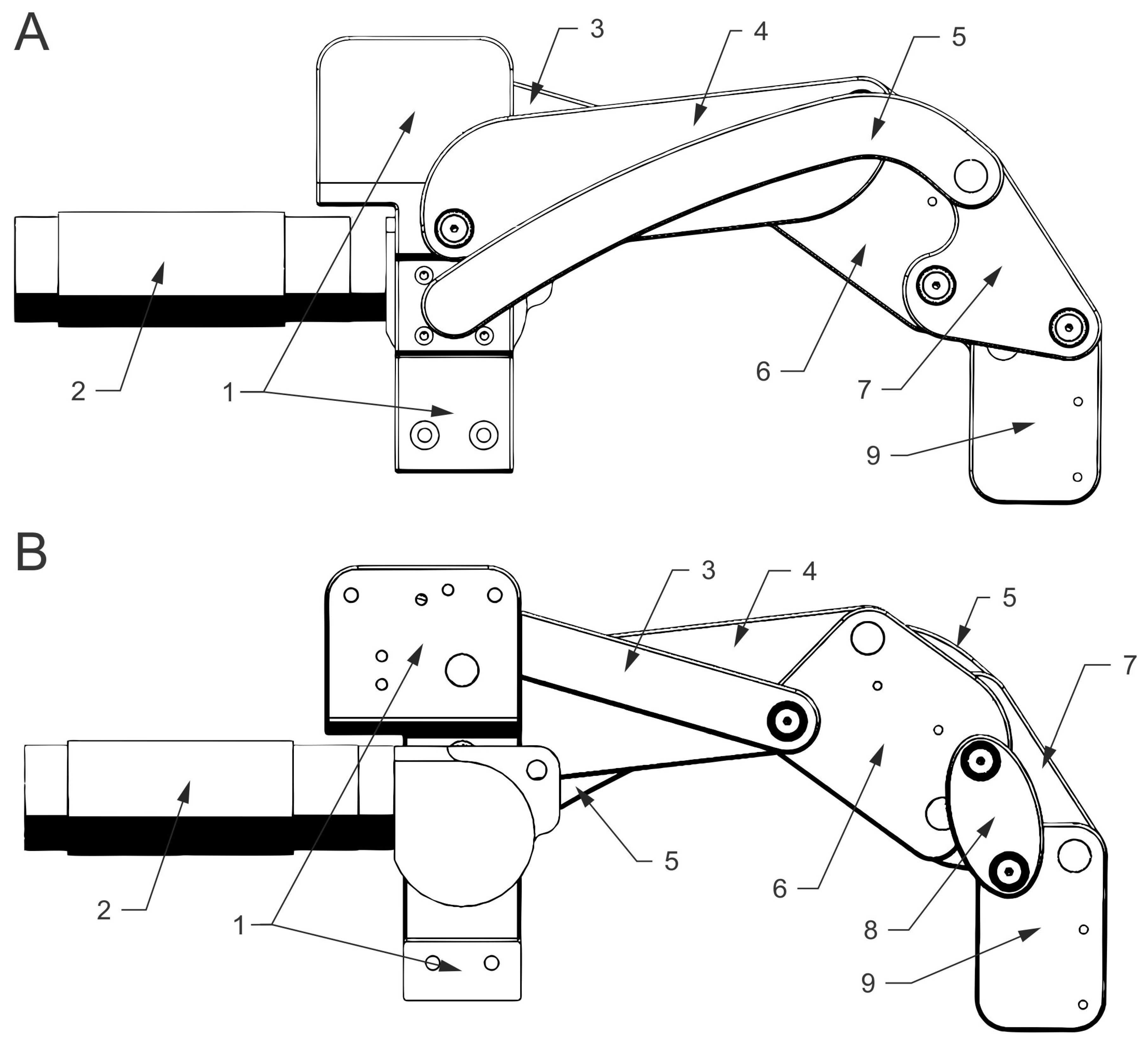
Figure 1 shows a lateral (A) and medial (B) view of the mechanism, depicting the successive connection of the segments. The numbers in Figure 1 correspond to the following parts—the mounting bracket (1), actuator (2), upper (3), middle (4), lower (5), central (6), triangular (7), oval (8), and the end (9) segment.
The dimensions and connections between the segments determine the mechanism’s movement, which, in turn, determines the movement of the wrist and fingers. The movement in the wrist is more dependent on the dimensions of the upper (3), middle (4), and partially the central (6) segment. By contrast, the movement of the fingers depends more on the dimensions of the oval (8), end (9), and lower (5) segment. The lower segment (5) is the only actively driven segment.
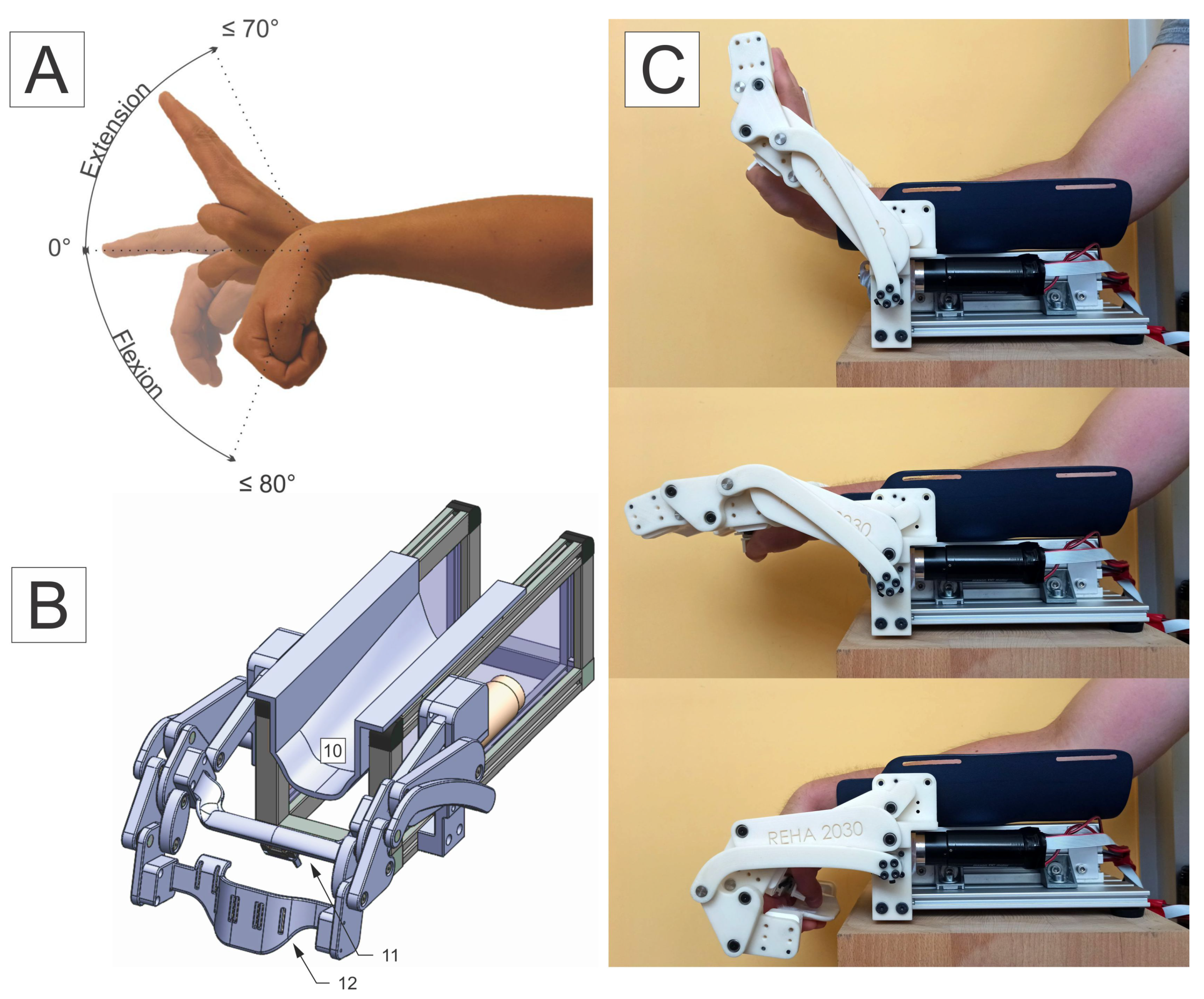
The proximal (11) and distal (12) finger rest connect the lateral and medial portion of the segments—they are marked, along with the forearm support (10), in Figure 2. The proximal finger rest (11) is installed between the central (6) segments, and the distal finger rest (12) is installed between the end (9) segments. The proximal finger rest (11) supports the metacarpophalangeal (MCP) joints, and the distal finger rest (12) supports the fingers beyond their proximal interphalangeal (PIP) joints. The PIP joints are not supported. The thumb is secured at the bottom of the proximal finger rest (12) inside of a fixation element, which allows for the position of the thumb to be adjusted laterally or medially. The fingers are individually fastened on the distal finger rest (12) with an elastic band, which runs through the openings in the finger rest—this allows the fingers to slide slightly back and forth along the finger rests while moving from flexion to extension. Distal finger rests of different dimensions can help adjust the distance between the proximal (11) and distal (12) finger rest, thus making the device adaptable to different lengths of patients’ fingers, as well as to the use with the left or right hand.
The mounting brackets (1) with actuators (2) connect the distal part of the device with its proximal part. The latter consists of an aluminium base—where the brackets are attached laterally and medially—and an aluminium profile with a forearm splint (10) attached to its top. This configuration allows the forearm splint (10) to be slid forward or back—distally or proximally—along the aluminium profile. Therefore, the distance between the forearm splint (10) and the proximal finger (11) rest can be reduced or increased, making it adjustable to the length of the patients’ metacarpal bones.
A mechanical blockage with discrete steps is implemented on the upper part of the bracket (1) to limit the device’s range of motion (ROM), ensuring safety and preventing excessive extension of the wrist and fingers. Movement into flexion is limited by the shape of the end segment (9) itself, preventing thumb compression in the flexed position.
The desired coupled movement of the wrist and fingers from flexion to extension (A), the 3D model of the device (B), and the actual device and its ROM (C) are depicted in Figure 2.
2.2. Actuation
Even though all of the device’s segments can move by actively rotating only one segment, we decided to use two actuators—one on each side of the mechanism—to neutralise sheer forces and ensure more even weight distribution. Therefore, two 24 V, 90 W, direct current (DC) motors with a graphite brush commutation system (maxon Group, Sachseln, Switzerland) actuate the device. Electrical motors were chosen because they are efficient, reliable, produce little noise, moderate torque and speeds, and have low operational and maintenance costs.
Each actuator has a housing diameter of 35 mm, weighs 340 g, and consists of a right-angle gearhead—with a 4.125:1 gear ratio and 86% efficiency; planetary gearhead—with a 5.8:1 gear ratio and 80% efficiency; and a DC motor—with a nominal torque of 105 mN·m. The selected gear ratios ensure the back-drivability of the device. This way, in case of a power failure, the residual motor torque is not high enough to lock the device in a fixed position—from where patients could not remove their hand—which is crucial for ensuring safe use in a nonclinical environment or by the patients themselves.
The configuration allows the device to produce at least 3.46 Nm of torque, which should be sufficient for enabling passive, assistive and active training modalities, especially for the patients who suffer from paresis, plegia and hypotonia, or mild to moderate spasticity.
2.3. Control System
The control system was designed upon a Raspberry Pi 4 microcomputer with a server version of a Raspbian operating system (OS). Raspbian is a Linux system distribution, optimised for Raspberry Pi hardware. Our control system uses its lite version—a barebones implementation, with a real-time kernel installed.
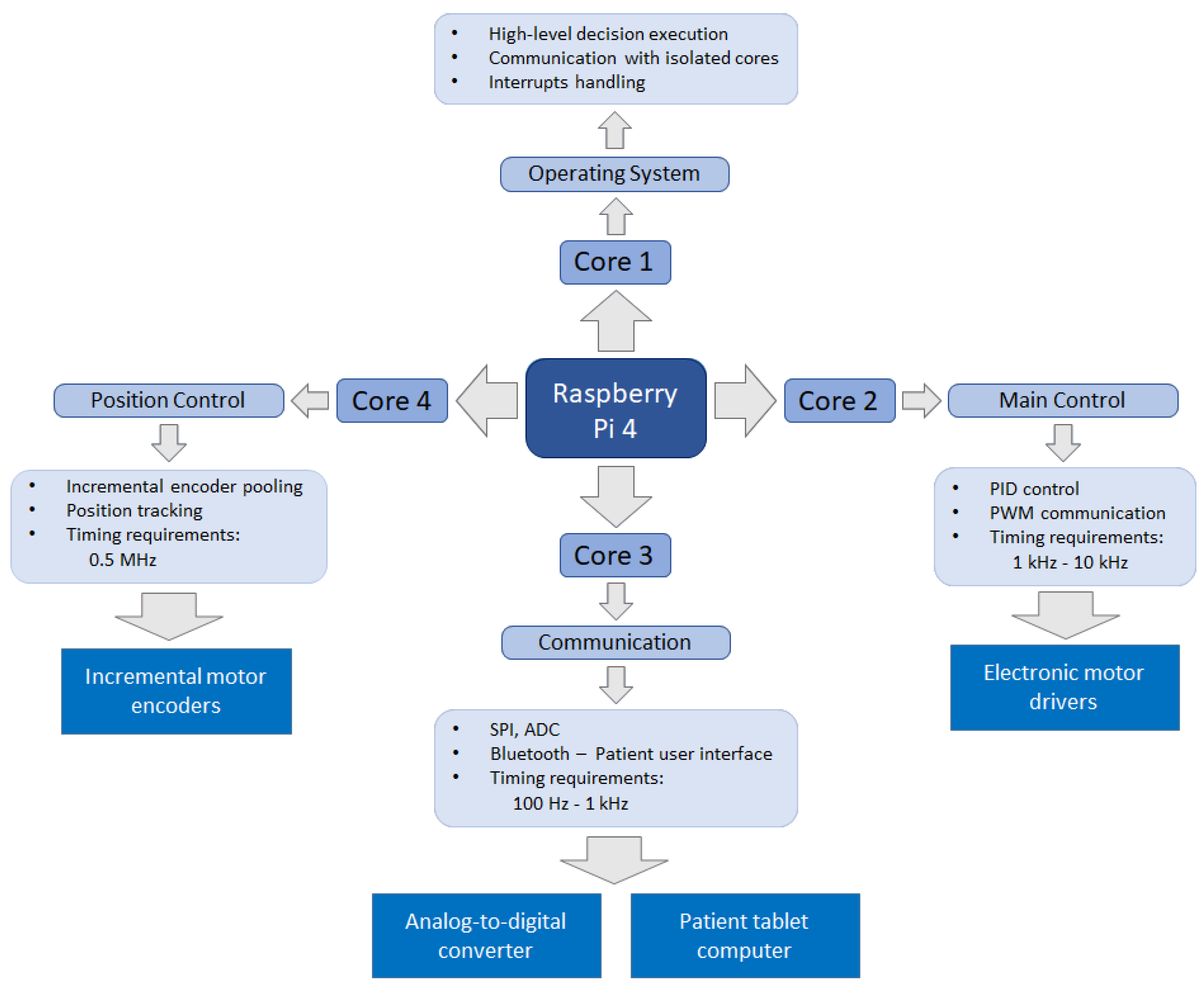
Robot control is a computationally demanding task and calls for a multithreaded approach. Therefore, the processes and tasks were divided among the four processing cores of the microcomputer, based on their timing requirements, as shown in Figure 3.
The program consists of several functionally split real-time and non-real-time processes. The real-time processes must be executed at specific time intervals, while the non-real-time processes do not require such strict timing. Therefore, the processes with similar time requirements run together on the same core. The first core is used for non-real-time processes such as high-level decision execution and OS functionalities. All other three cores are hidden from the OS interrupts and only work on their respective tasks: position and force control of the motors, communication, sensor data acquisition, and motor position tracking. Since the real-time processes managing cores are isolated from the Raspbian OS, their timing efficiency is increased.
The control system was developed using the C programming language, as it allows for faster running time than other frequently used programing languages, for example, Python.
The low-level control of the device includes:
- motor position control;
- communication with patient’s user interface, using Bluetooth connection;
- acquiring sensor data from:
- -
- strain gauge based force sensors,
- -
- incremental encoders of the motors,
- -
- torque measurements from the motors.
Motor drives, ESCON module 50/5 (maxon Group, Sachseln, Switzerland), regulate the force and velocity of the motors and enable analogue measurement of the motor’s torque. An incremental position encoder is integrated into each motor, monitored by the motor driver and the assigned microcomputer core. In order to enable telerehabilitation services, connectivity is implemented via Bluetooth connection of the device with the patient’s user interface. The latter is further connected to the web portal that enables the therapist to define or modify the therapy protocol, insight into individual therapy reports, and overall rehabilitation progress and adherence. The communication with hardware peripherals is provided by using pulse-width modulation (PWM) for the motor drives and serial peripheral interface (SPI) for the analogue-to-digital converter (ADC). The control scheme includes two groups of analogue signals, torque measurements from both motor drivers, and force measurements from the future force sensor. To interpret these signals, we use 10-bit ADC circuits.
The initial calibration of the device encompasses the controlled motion throughout the complete ROM in both directions. The end-positions of the joints are determined by the detection of the increased motor current values. The absolute joint position is calculated from the lower bound, counting the encoder outputs. The initialization procedure needs to be performed prior to donning; otherwise, the detection of excessive force at the distal finger rest stops the calibration process and issues an error message.
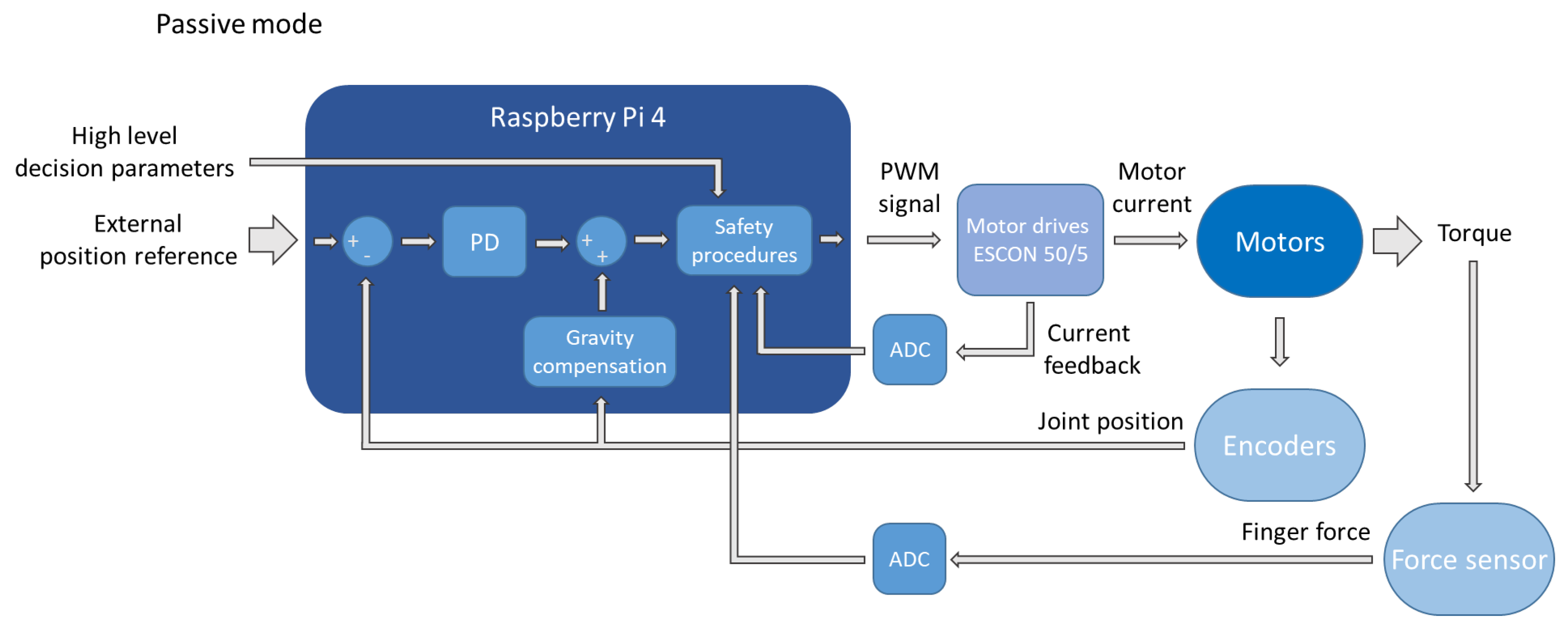
The high-level control is used to set the movement boundaries, the level of assistance or resistance, and to choose between the four training modalities—passive, assisted, active, and resistive. In the passive mode, where the device is active and the patient is passive, position control is implemented using the encoder feedback and the proportional-derivative (PD) control approach. Figure 4 depicts a block diagram of such a PD control. The first inputs of the controller are the high-level decision parameters defined by the therapist—such as maximum ROM and maximum permissible force. These parameters are considered in the safety procedures that limit or decrease the controller’s output to prevent violation of any safety requirements. Since the device should be positioned flat on the table during operation and the motion is executed only in the sagittal plane, the effect of gravity on the device is known and can therefore be compensated based on the joints’ positions. This compensation is performed in order to minimise the steady-state error. The motion reference is determined according to the prechosen parameters, while the proportional and derivative constants were tuned for critically damped behaviour.
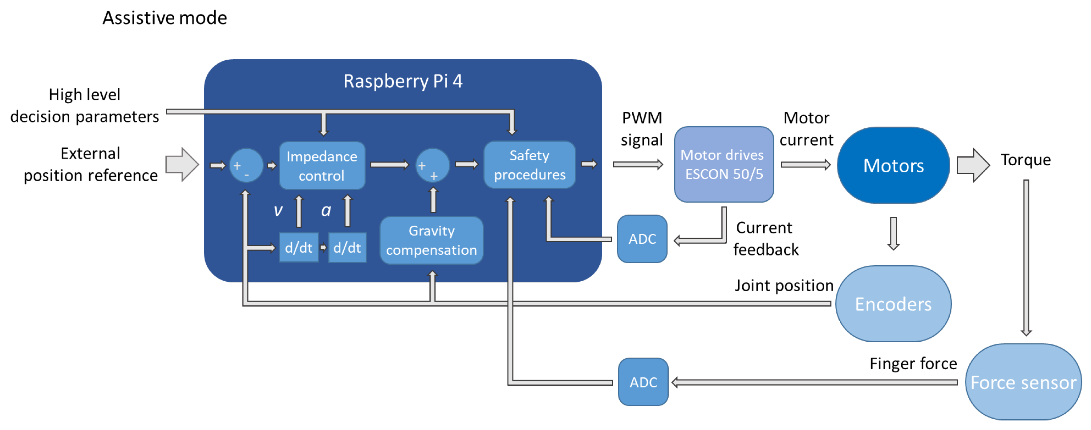
In the assistive mode, the device facilitates motion in parts of the movement, which the patients cannot yet perform themselves—only assisting the motion when needed. The device acts as a mass-damper-spring system in this mode, allowing the patient to deflect the device from the reference position by implementing an impedance control approach. Figure 5 depicts the block diagram of the assistive mode. It differs from the passive mode mainly in substituting the PD regulator for an impedance control block. This block calculates the desired force based on the current position, velocity, acceleration, and other high-level parameters—i.e., the level of assistance and the parts of movement where they are applicable.
In the active mode, where the patient is performing the movement through the set ROM without any active assistance from the device, the latter acts only as a measuring tool, gathering the signals from the incremental encoders, installed at motor axes, and force sensors, installed at the distal finger rest.
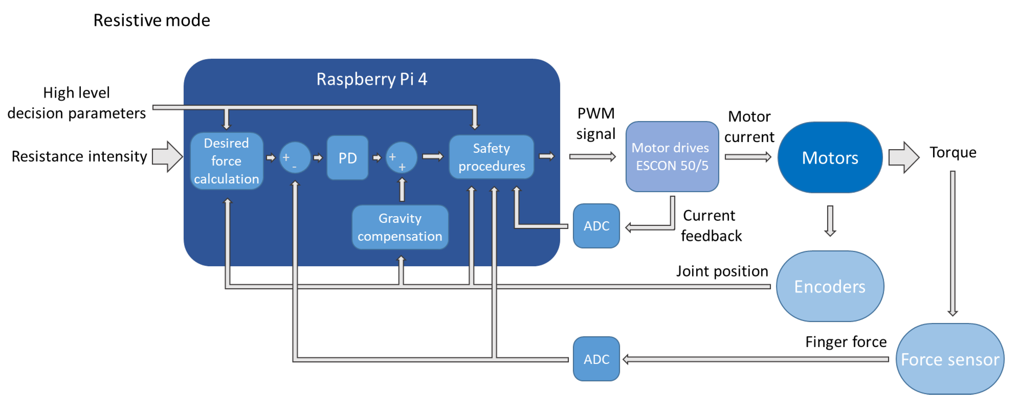
Direct force control is implemented in the resistive mode, where the device generates controlled resistance, opposing the patient’s motion. Figure 6 depicts the block diagram of the resistive mode. It is again similar to the passive mode, with the difference being that the force, instead of position, is regulated. Force feedback is provided by the strain gauges installed on the distal finger rest, while the reference force is determined by the position of the wrist joint, gradually decreasing in extension.
In all training modes, the data from the encoders and the interaction forces between the patient’s hand and the distal finger rest can be used for therapy progress evaluation. Even though this is still in the development stage, the high-level control already encompasses a human-controlled feed-forward position control and a passive training modality that guides the patient’s hand and wrist through cyclical flexion and extension every five seconds.
2.4. Experimental Validation
Validation measurements were carried out to investigate whether the device can replicate a coupled movement of the wrist and finger joints in healthy subjects, spanning through full flexion and extension.
2.4.1. Data Acquisition
The measurements took place in the Laboratory of Robotics at the Faculty of Electrical Engineering, Ljubljana, Slovenia.
The subjects were healthy individuals with no prior acute or chronic injuries that would limit the ROM of their wrist or fingers. The group of participants consisted of six people—four males and two females—mean age 29.5 years ± 6.7 years, mean body weight 73 kg ± 18 kg, and mean height 178 cm ± 12 cm. Anthropometric characteristics of the subjects—weight, height, and hand dimensions—are shown in Table 1.
In order to reduce the complexity of the measurements, our measurement protocol focused on the wrist, middle (MF), and pinkie (PF) finger—the third and fifth digit—joints. The thumb was not included in the analysis because this device does not actively target rehabilitation of its function. We chose to focus on the MF and PF because, in most people, MF is the longest; furthermore, it is positioned in the middle of the hand. Therefore, it can be, as such, also a good representation of the movement for the index and ring finger—the second and fourth digit. The PF, by contrast, is usually the shortest finger of the human hand and has its PIP and distal interphalangeal (DIP) joints’ axes noticeably misaligned with the other three fingers.
We used 11 active infrared light-emitting diode (LED) markers, sampled at 100 Hz—they were placed, posteriorly, on the forearm, ulnar, and radial styloid process, MCP, PIP, DIP joints, and fingertips of the MF and PF. The task for each protocol was described to the subjects, who then performed the three measurement protocols in the same order, for 30 s each:
- P0 protocol—active movement through the available ROM, spanning from the full coupled flexion of the wrist and fingers to their full extension, with the thumb held in opposition, only using the device’s proximal part to have the forearm secured in the splint. The movement speed was optional;
- P1 protocol—active movement through the device’s available ROM with a passive device equipped. The movement speed was optional;
- P2 protocol—passive, actuated movement through the device’s available ROM, where only the device was actively contributing to the movement. The device was moving through its available ROM so that one cycle of the movement—from flexion into extension and back—lasted five seconds.
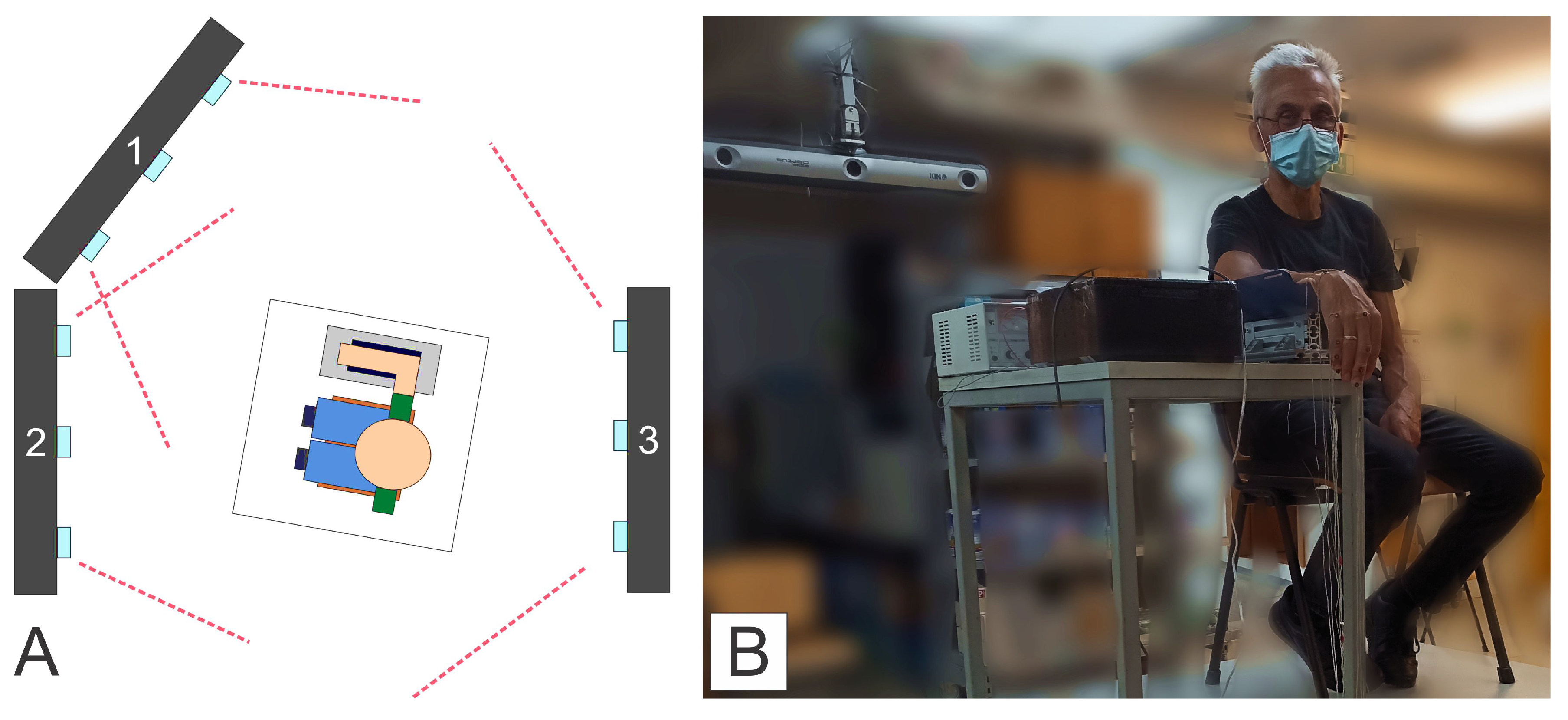
The 3D movement of the LED markers was captured using three Optotrak Certus NDI (Northern Digital) motion capture systems. According to [52], this motion tracking system has an absolute error of less than 0.1 mm. Figure 7 depicts the layout of the cameras 1, 2, and 3 (A), and a subject within the measurement set-up, prior to the start of the P0 protocol (B). Camera 1 was placed on a rack, positioned diagonally, above, and in front of the subject, capturing the motion through the middle part of the movement; camera 2 was placed below and angled up towards the subject, capturing the movement in the flexion; and camera 3 was set under the ceiling, behind the subject—it can also be seen in Figure 7B, capturing the movement in the extension.
2.4.2. Data Analysis
The Matlab (The MathWorks, Inc., Natick, MA, USA) programming platform was used to process and analyse the acquired data. We used spline interpolation to interpolate the missing markers and then filtered the data to remove undesirable artefacts—e.g., artefacts that have a temporal structure faster than the human motion. Therefore, a fourth-order, bidirectional Butterworth low-pass filter with a cutoff frequency of 5 Hz was utilised. The use of a bidirectional filter prevented the phase shift from affecting the data.
Measurement samples were then transformed into a common coordinate system, which had its origin coincide with the position of the marker on the radial styloid process. The negative x and the positive y-axes of the said coordinate system were determined by the markers placed on the ulnar styloid process and the forearm.
Then, the data were cut into individual, discrete moves, spanning either from the flexed into the extended or from the extended into the flexed position of the measured joints—which allowed us to categorise the motion data by the subject, the direction of the movement, and the experimental condition. We then inspected these discrete moves for unwanted artefacts and averaged them into base-line moves for each subject and protocol. However, since the movement in the P0 and P1 protocol was performed with a nonpredefined and varying speeds, we averaged the data in the spatial domain to obtain base-line trajectories for the moves of each joint during different protocols for each subject.
In order to compare trajectories between protocols, subjects’ base-line joint trajectories were computed from the P2 protocol. The P2 protocol was chosen for the base-line because it was performed at a constant speed and—as only the device was actively performing the movement—had the highest movement repeatability. Namely, we were expecting lower repeatability of the movement in the P0 protocol, as the subjects only had to simultaneously extend or flex the wrist and fingers—without a specific task to perform or an object to grasp. Therefore, we deemed the protocol P0 less suitable for the computation of the base-line joint trajectories.
The deviation from the base-line trajectory was then calculated along 100 equidistant points for every discrete move in P0 and P1 protocols. This way, we obtained the minimal distance from each equidistant point on the base-line trajectory to the corresponding point on the trajectory of the discrete move under consideration.
Signed deviation was used, meaning that the deviation is negative if the point on the discrete move is closer to the wrist joint than the point on the base-line trajectory. The deviation is positive if the point on the discrete move is further away from the wrist joint than the point on the base-line trajectory.
Lastly, the trajectories were normalised, starting with flexion and ending in extension, and averaged across all trials and across all subjects for each condition.
3. Results
The results regarding the shape, deviation of the trajectories, and their root-mean-square deviations (RMSD) are described in this section.
3.1. Form of the Motion Trajectories
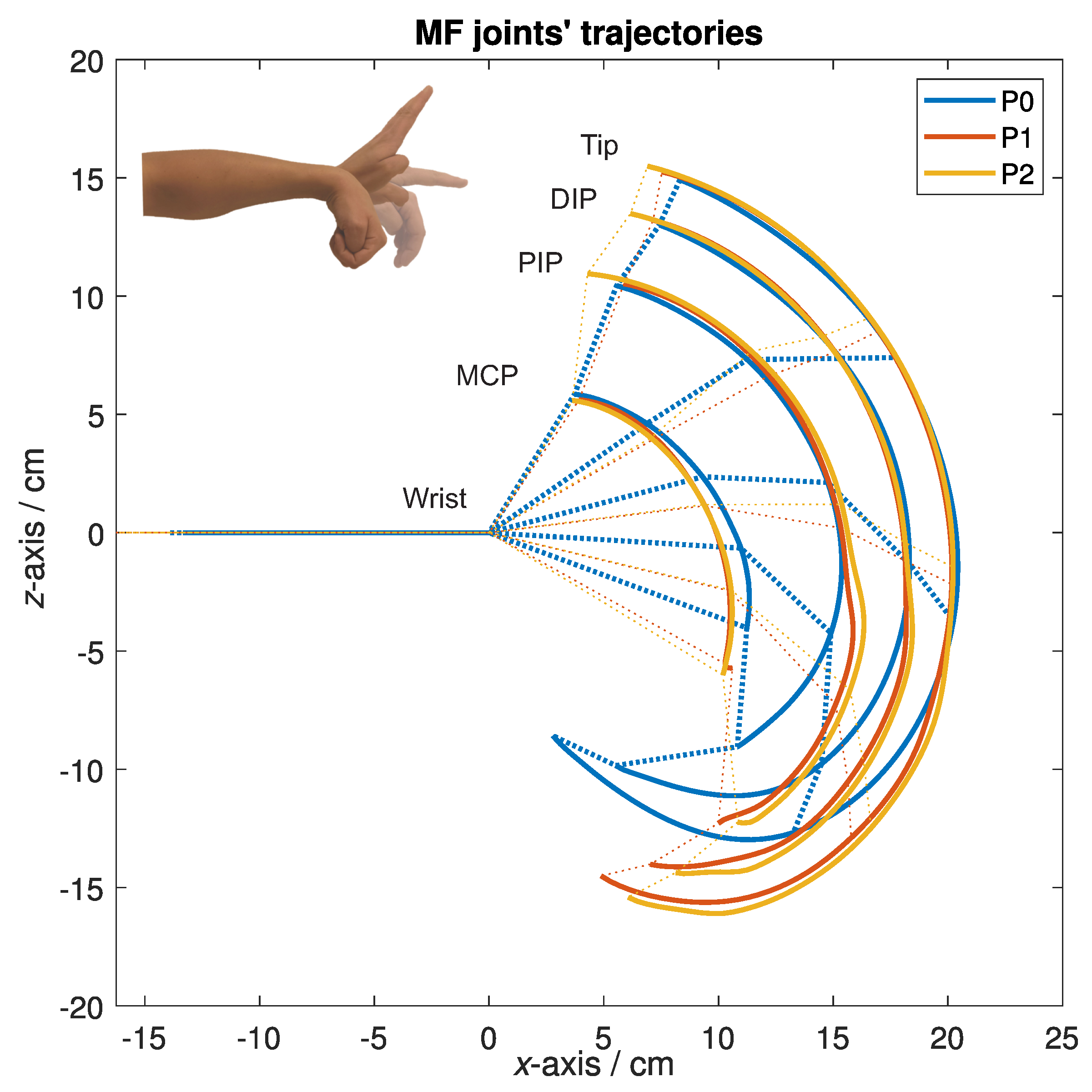
Figure 8 depicts representative trajectories of the markers on the MF joints for all three experimental conditions for one of the subjects. The trajectories are depicted in the sagittal plane—along the x and z-axis, showing how each marker was moving as the subject performed the protocols. The solid lines represent the trajectories obtained from each protocol—the blue colour represents the P0 protocol, the red colour represents the P1 protocol, and the yellow colour represents the P2 protocol. The dashed lines of the same colours are used to help visualise the corresponding positions of skeletal structures of the hand at the specific points along the trajectories—the markers were used as a representation of the wrist and finger joints positions. The point (0, 0) in Figure 8 represents the wrist, and the lines along the negative x-axis represent the forearm. From left to right, the trajectories in Figure 8 correspond to the movement of the markers on the MCP, PIP and DIP joint, and the tip of the MF.
The shape of the trajectories in Figure 8 shows a similarity of the wrist and finger movement across different experimental conditions. The shapes of trajectories in the P1 and P2 protocol, especially when moving into flexion, are expectedly similar, as the device constrained the subject’s movement. We can also observe a substantial difference between P0 and the other two protocols regarding the amount of flexion—during the P0 protocol the subjects could, in general, achieve a greater amount of flexion because they were able to flex the wrist and fingers completely, i.e., making a fist. That was not possible during the other two protocols, P1 and P2, as the device has a limited amount of flexion to prevent the bottom of the distal finger rest from compressing the thumb, which is fixated at the bottom of the proximal finger rest. Compared to P0 or P1, we can also observe a greater extension of the MF joints during P2 protocol, which could mean that the device moved the MF joints past their active ROM and into the passive ROM.
3.2. Trajectory Deviations
To numerically evaluate the similarity of the trajectories of the selected MF and PF joints across different protocols, we calculated the deviation of trajectories from a base-line joint’s trajectory, obtained during P2 protocol. The yellow lines in Figure 8 depict the base-line trajectories of the MF for one of the subjects during the P2 protocol; however, Figure 9 shows graphs with the normalised results, averaged across all subjects, for the MF’s and PF’s MCP joint and the fingertip.
Graphs in Figure 9 titled MF MCP and PF MCP show deviations in the movement of the MF’s and PF’s MCP joint, and graphs titled MF tip and PF tip show deviations in the MF’s and PF’s fingertip movements. The blue colour represents the P0, and the red represents the P1 protocol. Whiskers were added to the graphs to help visualise the standard deviation (SD) of the data. Both protocols were compared to the P2 protocol—yellow, which represents the baseline and can be barely seen, as its values are close to zero.
The deviations in the MCP joints can be interpreted as a base error since the trajectories of the MCP joints stem directly from the wrist flexion and extension and are, as such, not directly impacted by the device. The base error can be attributed to movements of the markers due to the skin’s elasticity.
To estimate how well the device mimics the movement of the unconstrained wrist and fingers of the healthy subjects, we can use the fingertip deviations. The normalised motion starts in the flexed position, at the left of the x-axis. The deviations in both graphs, MF tip and PF tip, show a considerable difference between the P0 and P2 protocols and also between the P0 and P1 protocols in the first half of the normalised motion, i.e., flexion; however, this was expected because, as stated before, during the P0, the subjects were able to move through their entire ROM, flexing their fingers into a fist. At the same time, that could not be performed during the P1 and P2 protocol, as the device has a limited ROM when moving into flexion, from both safety and mechanical standpoints. The normalised motion ends in the extended position, at the right of the x-axis, where the results are within the base error, indicating sufficient similarity of the trajectories between the P0 and P2 protocols, as well as the P1 and P2 protocols, meaning that the device adequately mimics the movement of the wrist and fingers into extension.
To further analyse the deviations of the trajectories for the MF, we computed the root-mean-square deviation (RMSD) of the deviation values between the P0 and P2 protocol for each of the subjects. We computed the RMSD values for the movement into flexion and the extension separately. Table 2 presents the obtained RMSD values and the SD for the MCP joint and the fingertip deviations.
The results from Table 2 are consistent with the results shown in Figure 9. Except for the subject B, the MF MCP deviations are within reasonable levels of error for both flexion and extension. Their cumulative average across the subjects, excluding the subject B, gives us a value of 0.5 cm, which most likely stems from an error due to skin elasticity, which is present in every measurement.
The same can be observed from the MF tip RMSD values during extension. The values are again within reasonable error levels, with most of them close to the 0.5 cm mark. That is, if we take that into account, the part of the RMSD values is probably a consequence of skin deformations due to finger fixations. Namely, Figure 9 shows that towards the extension, there are no major differences in the amplitude of the deviations for the P0 and P1 protocol, meaning that only the measurement error remains. An apparent exception here, according to Table 2 is subject F, where the RMSD value was 5.3 ± 1.0 cm. It could happen that the thumb stopped the movement of the bottom finger rest into further flexion, as subject F was the subject with the largest hand; however, the subject did not report any discomfort during the measurement protocols. The highest RMSD values were observed for the MF tip movement into flexion, with an average value of 2.4 cm. This means that the trajectory of the MF tip, when moving into flexion, was noticeably different when performing the P0 compared to the P2 protocol. The highest values were observed for the subject F.
Even with the outliers in the subjects B and F, the averaged values of the RMSD show that the MF’s MCP joint overall movement and the MF’s tip movement into extension did not differ considerably between the P0 and P2 protocols. On the other hand, higher values of the RMSD of the MF tip in Table 2, with noticeably more negative values of trajectory deviation, as seen in Figure 9, point toward an overall difference in the execution of the MF flexion between the P0 and P2 protocols and a reduced flexion during the P2 protocol.
4. Discussion
The experimental validation showed that the developed device is properly adapted to the anthropometric characteristics of measured subjects as none of the subjects experienced any discomfort during protocols P1 and P2.
High repeatability and intensity of the movement are essential in post-stroke rehabilitation protocols [4,17,18,19,20,21,24]. Results from Figure 8 and Figure 9 and Table 2 show that the similarity of the trajectories was higher during the P1 and P2 protocols, indicating higher movement repeatability when using the device—passive or active. Such a result was expected, as the device, regardless of a relatively complex mechanism, only has one active DOF, constraining the movement of otherwise many DOFs of an unconstrained hand.
Figure 9 and the values gathered in Table 2 show a considerable difference in finger trajectories during flexion between different protocols. Trajectories during extension, however, are relatively similar. We can deduce that subjects, while unconstrained, did not tend toward decoupled movement, i.e., first flexing the fingers and then the wrist, or vice-versa, which means that our device can adequately mimic the coupled extension of the wrist and fingers. That is a promising result since post-stroke patients usually have at least partially preserved ability to flex the wrist and fingers [53]; therefore, the hand rehabilitation protocols should prioritise recovering the ability to open the hand—to extend the wrist and fingers.
The selected actuators proved sufficiently strong to perform the passive training modality. We selected the actuators with gear ratios that were as high as possible and, at the same time, did not hinder the device’s back-drivability. In the future, we plan to test the device and its different training modalities on post-stroke patients with hemiplegia and low to moderate spasticity. It could happen that the actuators might not be strong enough to implement the resistive training modality. Even though more powerful actuators are available, their application poses an issue for the device’s independent, home telerehabilitation use, as a nonbackdrivable device seems unacceptable regarding the patient’s safety. However, such a nonbackdrivable version of the device could be used in an outpatient or ambulatory setting under the supervision of a qualified person.
5. Conclusions
The article presents a robotic device for post-stroke wrist and finger exercise. The device enables the wrist and finger joints’ coupled movement from flexion to extension, except for the thumb. Even though the device’s mechanism has numerous segments, it only has one actuated DOF. Alongside achieving the target movement—the coupled flexion and extension of the wrist and finger joints, provided with just one active DOF—the objectives were to develop a device that:
- is simple for donning and doffing, so that the patients could do it themselves, even in case of spasticity;
- is safe, so that the device can be used at home, in a nonclinical environment and also in the telerehabilitation applications;
- is adaptable to different patients in terms of their abilities and hand dimensions;
- is easy to use, portable, and has a relatively low manufacturing cost.
The movement that the device enables was compared to the unconstrained coupled movement of the wrist and finger joints of healthy subjects. Deviations from the base-line trajectory between measurement protocols and RMSD values show satisfactory results regarding the device’s movement, especially when moving into extension. The main two disadvantages of the developed solution are attributed to the targeted simplicity of the design and the safety assurance requirements. The limited torque capabilities of the actuation system originate from the back-drivability and the demand for inherent safety. The simple and affordable design, based on a single actuated DOF, imposes coupled motion of the wrist and finger joints; therefore, the fingers and wrist cannot be trained separately, which can be seen as a disadvantage. In the future, we are planning to also implement the assistive and resistive training modality. It is also planned to conduct measurements with post-stroke patients to further evaluate the device’s suitability for post-stroke telerehabilitation.
6. Patents
Patent application for the “Mechanism of the robotic device for the exercise of wrist and fingers” was submitted to the Slovenian Intellectual Property Office (SIPO) on 29 June 2021.
Author Contributions
Conceptualization, R.K., A.M. and A.R.; methodology, R.K., A.M. and A.R.; software, A.R.; validation, A.M. and A.R.; formal analysis, A.R. and A.M.; investigation, A.M. and A.R.; resources, R.K. and M.M.; data curation, A.R. and A.M.; writing—original draft preparation, A.M.; writing—review and editing, A.M., A.R. and R.K.; visualization, A.M. and A.R.; supervision, R.K.; project administration, R.K.; funding acquisition, R.K. and M.M. All authors have read and agreed to the published version of the manuscript.
Funding
This research was funded by the Slovenian Research Agency (ARRS) under Grant for research program P2–0228 and in part by project “Post-clinical Rehabilitation of Stroke Patients at Home at The Year 2030—Telerehabilitation as User Oriented Service’, REHA 2030”, Interreg V-A, Slovenia-Austria, ESRR No. SIAT258, which is aiming to develop a customised service model and the required technology for the post-clinic home-rehabilitation of stroke patients.
Institutional Review Board Statement
The study was conducted according to the guidelines of the Declaration of Helsinki and approved by the Ethics Committee of the Republic of Slovenia (NMEC) and the Ethics Committee of the University Rehabilitation Institute, Republic of Slovenia (80/03/15).
Informed Consent Statement
Informed consent was obtained from all subjects involved in the study.
Data Availability Statement
All the evaluation data are publicly available at the open repository for evaluation at: https://github.com/aRajhard/REHA2030_Robot.git (accessed on 20 December 2021).
Acknowledgments
We would like to thank the partners of the REHA2030 project from University Rehabilitation Institute, Republic of Slovenia, Private Hospital Laßnitzhöhe, the Carinthia University of Applied Sciences, and other affiliated freelance partners for their extensive feedback on the device’s design and suggestions for future improvements. We would also like to thank all the subjects who participated in the validation measurements.
Conflicts of Interest
The authors declare no conflict of interest.
Abbreviations
The following abbreviations are used in this manuscript:
| ADC | Analogue-to-digital converter |
| ADL | Activities of daily living |
| DC | Direct current |
| DIP | Distal interphalangeal (joint) |
| DOF | Degree of freedom |
| LED | Light-emitting diode |
| MCP | Metacarpophalangeal (joint) |
| MF | Middle finger |
| OS | Operating system |
| PF | Pinkie finger |
| PD | Proportional-derivative |
| PIP | Proximal interphalangeal (joint) |
| PWM | Pulse-width modulation |
| RMSD | Root-mean-square deviation |
| ROM | Range of motion |
| SD | Standard deviation |
| SPI | Serial peripheral interface |
References
- Dantes, E.; Axelerad, S.D.; Stroe, A.Z.; Axelerad, D.D.; Axelerad, A.D. The rehabilitation of hemiparesis after stroke. Ovidius Univ. Ann. Ser. Phys. Educ. Sport. Mov. Health 2020, 20, 5–10. [Google Scholar]
- Mackay, J.; Mensah, G.A.; Greenlund, K. The Atlas of Heart Disease and Stroke; World Health Organization: Geneva, Switzerland, 2004. [Google Scholar]
- Luengo-Fernandez, R.; Violato, M.; Candio, P.; Leal, J. Economic burden of stroke across Europe: A population-based cost analysis. Eur. Stroke J. 2020, 5, 17–25. [Google Scholar] [CrossRef]
- Schaechter, J.D. Motor rehabilitation and brain plasticity after hemiparetic stroke. Prog. Neurobiol. 2004, 73, 61–72. [Google Scholar] [CrossRef]
- Li, S. Spasticity, motor recovery, and neural plasticity after stroke. Front. Neurol. 2017, 8, 120. [Google Scholar] [CrossRef] [Green Version]
- Kuo, C.L.; Hu, G.C. Post-stroke spasticity: A review of epidemiology, pathophysiology, and treatments. Int. J. Gerontol. 2018, 12, 280–284. [Google Scholar] [CrossRef]
- Lang, C.E.; Bland, M.D.; Bailey, R.R.; Schaefer, S.Y.; Birkenmeier, R.L. Assessment of upper extremity impairment, function, and activity after stroke: Foundations for clinical decision making. J. Hand Ther. 2013, 26, 104–115. [Google Scholar] [CrossRef] [PubMed] [Green Version]
- Feys, H.M.; De Weerdt, W.J.; Selz, B.E.; Cox Steck, G.A.; Spichiger, R.; Vereeck, L.E.; Putman, K.D.; Van Hoydonck, G.A. Effect of a therapeutic intervention for the hemiplegic upper limb in the acute phase after stroke: A single-blind, randomized, controlled multicenter trial. Stroke 1998, 29, 785–792. [Google Scholar] [CrossRef] [PubMed]
- Dovat, L.; Lambercy, O.; Gassert, R.; Maeder, T.; Milner, T.; Leong, T.C.; Burdet, E. HandCARE: A cable-actuated rehabilitation system to train hand function after stroke. IEEE Trans. Neural Syst. Rehabil. Eng. 2008, 16, 582–591. [Google Scholar] [CrossRef] [PubMed]
- Hendricks, H.T.; Van Limbeek, J.; Geurts, A.C.; Zwarts, M.J. Motor recovery after stroke: A systematic review of the literature. Arch. Phys. Med. Rehabil. 2002, 83, 1629–1637. [Google Scholar] [CrossRef]
- Nakayama, H.; Jørgensen, H.S.; Raaschou, H.O.; Olsen, T.S. Recovery of upper extremity function in stroke patients: The Copenhagen stroke study. Arch. Phys. Med. Rehabil. 1994, 75, 394–398. [Google Scholar] [CrossRef]
- Gresham, G.; Duncan, P.; Stason, W.; Adams, H.; Adelman, A.; Alexander, D.; Bishop, D.; Diller, L.; Donaldson, N.; Granger, C.; et al. Post-Stroke Rehabilitation; US Department of Health and Human Services, Public Health Service, Agency for Health Care Policy and Research: Rockville, MD, USA, 1995.
- Wissel, J.; Manack, A.; Brainin, M. Toward an epidemiology of poststroke spasticity. Neurology 2013, 80, 13–19. [Google Scholar] [CrossRef] [PubMed]
- Zorowitz, R.D.; Gillard, P.J.; Brainin, M. Post-stroke spasticity: Sequelae and burden on stroke survivors and caregivers. Neurology 2013, 80, 45–52. [Google Scholar] [CrossRef] [PubMed]
- Zeng, H.; Chen, J.; Guo, Y.; Tan, S. Prevalence and risk factors for spasticity after stroke: A systematic review and meta-analysis. Front. Neurol. 2021, 11, 1884. [Google Scholar] [CrossRef]
- Chino, N.; Melvin, J.L. Functional Evaluation of Stroke Patients; Springer: Tokyo, Japan, 1996. [Google Scholar]
- Prange, G.; Jannink, M.; Groothuis-Oudshoorn, C.; Hermens, H.; Ijzerman, M. Systematic review of the effect of robot-aided therapy on recovery of the hemiparetic arm after stroke. J. Rehabil. Res. Dev. 2009, 43, 171–184. [Google Scholar] [CrossRef] [Green Version]
- Barreca, S.; Wolf, S.L.; Fasoli, S.; Bohannon, R. Treatment interventions for the paretic upper limb of stroke survivors: A critical review. Neurorehabilit. Neural Repair 2003, 17, 220–226. [Google Scholar] [CrossRef]
- Woldag, H.; Hummelsheim, H. Evidence-based physiotherapeutic concepts for improving arm and hand function in stroke patients. J. Neurol. 2002, 249, 518–528. [Google Scholar] [CrossRef]
- Van Der Lee, J.H.; Snels, I.A.; Beckerman, H.; Lankhorst, G.J.; Wagenaar, R.C.; Bouter, L.M. Exercise therapy for arm function in stroke patients: A systematic review of randomized controlled trials. Clin. Rehabil. 2001, 15, 20–31. [Google Scholar] [CrossRef] [Green Version]
- Goljar, N. Klinične smernice za rehabilitacijo bolnikov po preboleli možganski kapi. Rehabilitacija 2014, 13, 12–18. [Google Scholar]
- Oujamaa, L.; Relave, I.; Froger, J.; Mottet, D.; Pelissier, J.Y. Rehabilitation of arm function after stroke. Literature review. Ann. Phys. Rehabil. Med. 2009, 52, 269–293. [Google Scholar] [CrossRef] [PubMed]
- Sarakoglou, I.; Tsagarakis, N.G.; Caldwell, D.G. Occupational and physical therapy using a hand exoskeleton based exerciser. In Proceedings of the 2004 IEEE/RSJ International Conference on Intelligent Robots and Systems (IROS) (IEEE Cat. No. 04CH37566), Sendai, Japan, 28 September–2 October 2004; Volume 3, pp. 2973–2978. [Google Scholar]
- Langhorne, P.; Coupar, F.; Pollock, A. Motor recovery after stroke: A systematic review. Lancet Neurol. 2009, 8, 741–754. [Google Scholar] [CrossRef]
- Boyd, R.N.; Ada, L. Physiotherapy management of spasticity. In Upper Motor Neuron Syndrome and Spasticity: Clinical Management and Neurophysiology; Cambridge University Press: Cambridge, UK, 2001; pp. 79–81. [Google Scholar]
- Coroian, F.; Jourdan, C.; Bakhti, K.; Palayer, C.; Jaussent, A.; Picot, M.C.; Mottet, D.; Julia, M.; Bonnin, H.Y.; Laffont, I. Upper limb isokinetic strengthening versus passive mobilization in patients with chronic stroke: A randomized controlled trial. Arch. Phys. Med. Rehabil. 2018, 99, 321–328. [Google Scholar] [CrossRef]
- Radomski, M.V.; Latham, C.A.T. Occupational Therapy for Physical Dysfunction; Lippincott Williams & Wilkins: Philadelphia, PA, USA, 1995. [Google Scholar]
- Volpe, B.T.; Ferraro, M.; Krebs, H.I.; Hogan, N. Robotics in the rehabilitation treatment of patients with stroke. Curr. Atheroscler. Rep. 2002, 4, 270–276. [Google Scholar] [CrossRef]
- Krebs, H.I.; Hogan, N.; Aisen, M.L.; Volpe, B.T. Robot-aided neurorehabilitation. IEEE Trans. Rehabil. Eng. 1998, 6, 75–87. [Google Scholar] [CrossRef] [Green Version]
- Brackenridge, J.; Bradnam, L.V.; Lennon, S.; Costi, J.J.; Hobbs, D.A. A review of rehabilitation devices to promote upper limb function following stroke. Neurosci. Biomed. Eng. (Discontin.) 2016, 4, 25–42. [Google Scholar] [CrossRef]
- Meng, Q.; Xie, Q.; Yu, H. Upper-limb rehabilitation robot: State of the art and existing problems. In Proceedings of the 12th International Convention on Rehabilitation Engineering and Assistive Technology, Shanghai, China, 13–16 July 2018; pp. 155–158. [Google Scholar]
- Basteris, A.; Nijenhuis, S.M.; Stienen, A.H.; Buurke, J.H.; Prange, G.B.; Amirabdollahian, F. Training modalities in robot-mediated upper limb rehabilitation in stroke: A framework for classification based on a systematic review. J. Neuroeng. Rehabil. 2014, 11, 111. [Google Scholar] [CrossRef] [Green Version]
- Ates, S.; Haarman, C.J.; Stienen, A.H. SCRIPT passive orthosis: Design of interactive hand and wrist exoskeleton for rehabilitation at home after stroke. Auton. Robot. 2017, 41, 711–723. [Google Scholar] [CrossRef] [Green Version]
- Hesse, S.; Werner, C.; Pohl, M.; Rueckriem, S.; Mehrholz, J.; Lingnau, M. Computerized arm training improves the motor control of the severely affected arm after stroke: A single-blinded randomized trial in two centers. Stroke 2005, 36, 1960–1966. [Google Scholar] [CrossRef]
- Hsieh, Y.W.; Wu, C.Y.; Lin, K.C.; Yao, G.; Wu, K.Y.; Chang, Y.J. Dose–response relationship of robot-assisted stroke motor rehabilitation: The impact of initial motor status. Stroke 2012, 43, 2729–2734. [Google Scholar] [CrossRef] [Green Version]
- Lambercy, O.; Dovat, L.; Gassert, R.; Burdet, E.; Teo, C.L.; Milner, T. A haptic knob for rehabilitation of hand function. IEEE Trans. Neural Syst. Rehabil. Eng. 2007, 15, 356–366. [Google Scholar] [CrossRef]
- Hesse, S.; Schulte-Tigges, G.; Konrad, M.; Bardeleben, A.; Werner, C. Robot-assisted arm trainer for the passive and active practice of bilateral forearm and wrist movements in hemiparetic subjects. Arch. Phys. Med. Rehabil. 2003, 84, 915–920. [Google Scholar] [CrossRef]
- Stroke, P. Robotic devices and brain: Machine interfaces for hand rehabilitation post-stroke. J. Rehabil. Med. 2017, 49, 449–460. [Google Scholar]
- Stinear, C.M.; Lang, C.E.; Zeiler, S.; Byblow, W.D. Advances and challenges in stroke rehabilitation. Lancet Neurol. 2020, 19, 348–360. [Google Scholar] [CrossRef]
- Timmermans, A.A.; Seelen, H.A.; Willmann, R.D.; Kingma, H. Technology-assisted training of arm-hand skills in stroke: Concepts on reacquisition of motor control and therapist guidelines for rehabilitation technology design. J. Neuroeng. Rehabil. 2009, 6, 1–18. [Google Scholar] [CrossRef] [Green Version]
- Goljar Kregar, N.; Kotnik, S. Ocenjevanje funkcije roke pri bolnikih po možganski kapi s Southamptonskim testom SHAP. Rehabilitacija 2015, 14, 4–10. [Google Scholar]
- Paik, Y.R.; Kim, S.K.; Lee, J.S.; Jeon, B.J. Simple and task-oriented mirror therapy for upper extremity function in stroke patients: A pilot study. Hong Kong J. Occup. Ther. 2014, 24, 6–12. [Google Scholar] [CrossRef] [Green Version]
- Peretti, A.; Amenta, F.; Tayebati, S.K.; Nittari, G.; Mahdi, S.S. Telerehabilitation: Review of the state-of-the-art and areas of application. JMIR Rehabil. Assist. Technol. 2017, 4, e7511. [Google Scholar] [CrossRef]
- Suso-Martí, L.; La Touche, R.; Herranz-Gómez, A.; Angulo-Díaz-Parreño, S.; Paris-Alemany, A.; Cuenca-Martínez, F. Effectiveness of Telerehabilitation in Physical Therapist Practice: An Umbrella and Mapping Review with Meta–Meta-Analysis. Phys. Ther. 2021, 101, pzab075. [Google Scholar] [CrossRef]
- Fausti, D.; Seneci, C. A Hand Rehabilitation Device. European Patent EP2549971B1A, 21 March 2011. Available online: https://patents.google.com/patent/EP2549971B1/de?oq=EP2549971B1 (accessed on 16 July 2021).
- Saringer, J.H. Device for Imparting Continuous Passive Motion to Human Joints. U.S. Patent US4665900A, 31 December 1984. Available online: https://patents.google.com/patent/US4665900A/en?oq=US4665900A (accessed on 16 July 2021).
- Weinzweig, N. Removable Flexible Finger Covering with Fingertip Connector Clip. U.S. Patent US5261393A, 17 September 1992. Available online: https://patents.google.com/patent/US5261393A/en?oq=US5261393A (accessed on 16 July 2021).
- Brook, A.H.; Carian, P.J.; Katzin, L.; Landsinger, E.E.; Moore, J.D.; Rotter, L.D.; Stanley, S. Continuous Passive Motion Devices and Methods. U.S. Patent US4875469A, 13 June 1988. Available online: https://patents.google.com/patent/US4875469A/en?oq=US4875469A (accessed on 16 July 2021).
- Moon, I.; Bae, J. Wearable Excercise Device for Upper Limb Rehabilitation. Korean Patent KR101546882B1, 6 September 2013. Available online: https://patents.google.com/patent/KR101546882B1/en?oq=KR101546882B1 (accessed on 16 July 2021).
- Kim, Y.; Moon, I. KR101126637B1: Upper-Limb Rehabilitation Robot and Parallel Link Mechanism. Korean Patent KR101126637B1, 10 September 2009. Available online: https://patents.google.com/patent/KR101126637B1/en?oq=KR101126637B1 (accessed on 16 July 2021).
- Koeneman, E.J.; Koeneman, J.B.; Herring, D.E.; Schultz, R.S. System and Method for Neuromuscular Reeducation. U.S. Patent US8214029B2, 12 April 2010. Available online: https://patents.google.com/patent/US8214029B2/en?oq=US8214029B2 (accessed on 16 July 2021).
- States, R.; Pappas, E. Precision and repeatability of the Optotrak 3020 motion measurement system. J. Med Eng. Technol. 2006, 30, 11–16. [Google Scholar] [CrossRef]
- Brokaw, E.B.; Holley, R.J.; Lum, P.S. Hand spring operated movement enhancer HandSOME device for hand rehabilitation after stroke. In Proceedings of the 2010 Annual International Conference of the IEEE Engineering in Medicine and Biology, Buenos Aires, Argentina, 31 August–4 September 2010; pp. 5867–5870. [Google Scholar]
Figure 1.
Sketch of the device’s mechanism, lateral (A) and medial (B) view. The numbers in the figures correspond to the following parts—1: mounting bracket, 2: actuator, 3: upper segment, 4: middle segment, 5: lower segment, 6: central segment, 7: triangular segment, 8: oval segment, and 9: end segment.

Figure 2.
The desired movement (A), 3D model with supportive parts of the device marked—10: forearm support, 11: proximal finger rest, and 12: distal finger rest (B), and the actual device, moving through its available ROM (C).
Figure 2.
The desired movement (A), 3D model with supportive parts of the device marked—10: forearm support, 11: proximal finger rest, and 12: distal finger rest (B), and the actual device, moving through its available ROM (C).

Figure 3.
Multithreaded approach to robot control and embedded hardware communication.

Figure 4.
A block diagram for the passive mode of operation with all the used hardware and signals.

Figure 5.
A block diagram for the assistive mode of operation with all the used hardware and signals.
Figure 5.
A block diagram for the assistive mode of operation with all the used hardware and signals.

Figure 6.
A block diagram for the resistive mode of operation with all the used hardware and signals.
Figure 6.
A block diagram for the resistive mode of operation with all the used hardware and signals.

Figure 7.
The measurement set up with three cameras—1, 2, 3 (A), and a subject within the measurement set-up (B).
Figure 7.
The measurement set up with three cameras—1, 2, 3 (A), and a subject within the measurement set-up (B).

Figure 8.
The MF joints’ trajectories in the sagittal plane for one of the subjects and all three experimental protocols: P0—blue, P1—red, and P2—yellow.
Figure 8.
The MF joints’ trajectories in the sagittal plane for one of the subjects and all three experimental protocols: P0—blue, P1—red, and P2—yellow.

Figure 9.
Deviation of the finger joints’ trajectories from their base-line trajectory.


Table 1.
Sex, age, dominant arm, and anthropometric properties of the subjects.
| Sex | Age/Years | Weight/kg | Height/cm | DA | W-MF MCP/cm | W-PF MCP/cm | LMF/cm | LPF/cm | HW/cm | |
|---|---|---|---|---|---|---|---|---|---|---|
| Subject A | M | 25 | 75 | 194 | R | 10.5 | 9.6 | 11.0 | 7.9 | 8.0 |
| Subject B | M | 27 | 88 | 186 | R | 10.3 | 8.3 | 10.7 | 7.9 | 8.6 |
| Subject C | F | 28 | 60 | 164 | R | 9.4 | 7.4 | 9.6 | 7.2 | 7.8 |
| Subject D | M | 25 | 65 | 174 | R | 9.8 | 8.8 | 11.0 | 8.0 | 8.2 |
| Subject E | F | 27 | 52 | 169 | R | 9.5 | 8.6 | 9.8 | 7.6 | 7.5 |
| Subject F | M | 43 | 100 | 186 | R | 9.8 | 8.8 | 11.0 | 8.0 | 10.0 |
DA—dominant arm, where R is the right dominant arm and L is the left dominant arm. W-MF MCP—distance between the wrist and the MF MCP joint; length of the third metacarpal bone. W-PF MCP—distance between the wrist and the PF MCP joint; length of the fifth metacarpal bone. LMF—distance between the MF MCP joint and the MF tip; length of the MF. LPF—distance between the PF MCP joint and the PF tip; length of the PF. HW—hand width, with thumb in opposition
Table 2.
The RMSD values between the P0 and P2 for each of the subjects.
| MF MCP | MF Tip | |||
|---|---|---|---|---|
| Flexion/cm | Extension/cm | Flexion/cm | Extension/cm | |
| Subject A | 0.3 ± 0.1 | 0.6 ± 0.1 | 2.9 ± 1.3 | 0.7 ± 0.4 |
| Subject B | 1.7 ± 0.1 | 1.4 ± 0.1 | 1.1 ± 0.2 | 0.8 ± 0.1 |
| Subject C | 0.5 ± 0.1 | 0.2 ± 0.1 | 1.3 ± 0.6 | 0.4 ± 0.2 |
| Subject D | 0.7 ± 0.2 | 0.4 ± 0.1 | 1.8 ± 0.6 | 0.2 ± 0.1 |
| Subject E | 0.7 ± 0.3 | 0.4 ± 0.2 | 2.0 ± 0.6 | 0.9 ± 0.3 |
| Subject F | 0.5 ± 0.1 | 0.2 ± 0.2 | 5.3 ± 1.0 | 1.6 ± 0.1 |
| Average | 0.7 ± 0.5 | 0.5 ± 0.4 | 2.4 ± 1.6 | 0.7 ± 0.5 |
Publisher’s Note: MDPI stays neutral with regard to jurisdictional claims in published maps and institutional affiliations. |
© 2022 by the authors. Licensee MDPI, Basel, Switzerland. This article is an open access article distributed under the terms and conditions of the Creative Commons Attribution (CC BY) license (https://creativecommons.org/licenses/by/4.0/).
Share and Cite
MDPI and ACS Style
Mandeljc, A.; Rajhard, A.; Munih, M.; Kamnik, R. Robotic Device for Out-of-Clinic Post-Stroke Hand Rehabilitation. Appl. Sci. 2022, 12, 1092. https://doi.org/10.3390/app12031092
AMA Style
Mandeljc A, Rajhard A, Munih M, Kamnik R. Robotic Device for Out-of-Clinic Post-Stroke Hand Rehabilitation. Applied Sciences. 2022; 12(3):1092. https://doi.org/10.3390/app12031092
Chicago/Turabian StyleMandeljc, Ana, Aleksander Rajhard, Marko Munih, and Roman Kamnik. 2022. "Robotic Device for Out-of-Clinic Post-Stroke Hand Rehabilitation" Applied Sciences 12, no. 3: 1092. https://doi.org/10.3390/app12031092
Note that from the first issue of 2016, this journal uses article numbers instead of page numbers. See further details here.