Article

Energy Management Strategy for Hybrid Multimode Powertrains: Influence of Inertial Properties and Road Inclination

Department of Mechanical and Aerospace Engineering, Politecnico di Torino, Corso Duca degli Abruzzi 24, 10129 Turin, Italy
*
Author to whom correspondence should be addressed.
Appl. Sci. 2021, 11(24), 11752; https://doi.org/10.3390/app112411752
Submission received: 19 October 2021 / Revised: 24 November 2021 / Accepted: 1 December 2021 / Published: 10 December 2021
(This article belongs to the Special Issue Optimal Design and Control of Thermal Hybrid Powertrains)

Abstract

:
Multimode hybrid powertrains have captured the attention of automotive OEMs for their flexible nature and ability to provide better and optimized efficiency levels. However, the presence of multiple actuators, with different efficiency and dynamic characteristics, increases the problem complexity for minimizing the overall power losses in each powertrain operating condition. The paper aims at providing a methodology to select the powertrain mode and set the reference torques and angular speeds for each actuator, based on the power-weighted efficiency concept. The power-weighted efficiency is formulated to normalize the efficiency contribution from each power source and to include the inertial properties of the powertrain components as well as the vehicle motion resistance forces. The approach, valid for a wide category of multimode powertrain architectures, is then applied to the specific case of a two-mode hybrid system where the engagement of one of the two clutches enables an Input Split or Compound Split operative mode. The simulation results obtained with the procedure prove to be promising in avoiding excessive accelerations, drift of powertrain components, and in managing the power flow for uphill and downhill vehicle conditions.

1. Introduction

Regarding the increasingly serious issues of energy shortage and environmental pollution, attention from governments, research institutions and automobile companies is shifting from traditional fuel vehicles to new innovative solutions [1,2,3]. To reduce air pollution and emissions of greenhouse gases, many governments incentivize the production of zero emissions vehicles (ZEVs), such as battery electric vehicles (BEVs) and fuel cell electric vehicles (FCEVs). The German Parliament has recently decided to ban internal combustion engine vehicles (ICEVs) by 2030 [4]. Many other countries have announced that they will proceed with a similar policy between 2025 and 2050 [5]. However, most of these bans do not include hybrid electric vehicles (HEVs) and plug-in hybrid electric vehicles (PHEVs), which include ICEs as a power source. While the shift from ICEVs to ZEVs has already started, it may take decades for customers to select ZEVs as a cost effective and convenient choice. Moreover, batteries still require decisive improvements to be considered as unique energy sources, vehicle cost should reduce and infrastructure should be globally adapted to the new changes. In the meantime, thermal efficiency of ICEs is expected to further improve and HEVs and PHEVs are expected to play a significant role. Hybrid electric vehicles represent the best tradeoff between traditional fuel vehicles and pure electric vehicles (EVs), thus becoming the perfect transitional stage. The fuel efficiency of HEV has traditionally improved through new developments in aerodynamics, engine technology, light-weight materials, and innovative concepts for powertrain component design [2,6]. HEV uses two power sources: an internal combustion engine and an electric battery; thus, the fuel economy varies substantially depending on the power source used to meet the vehicle request. The introduction of hybrid powertrain has allowed a substantial step forward in the direction of energy saving. Indeed, the presence of one or more electric motors does not only provides a significant benefit in terms of efficiency performance by optimizing the engine operating point, but it also introduces the idea of regenerating part of the energy dissipated during braking [7,8]. Hybrid powertrains are generally divided into three categories: series, parallel, and series–parallel (power-split), as defined by Chan [9]. In series architecture, the engine output power is first converted into electric power which can be used to either charges the battery or to propel the wheels through the same electric motor [10]. The parallel configuration allows both the engine and the electric motor to deliver power in parallel to drive the wheels [11]. The series–parallel incorporates the characteristics of both the series and parallel configurations, but including an additional mechanical link compared with the series architecture and an additional generator compared with the parallel architecture. The power-split category represents the most attractive solution due to its multimode and flexible nature which guarantees an adaptive solution to every vehicle working condition and fully realizes the powertrain potential to achieve both better fuel economy and improved drivability [12,13].
The major issue of series–parallel powertrain is represented by the multiple energy sources that require a complex power flow management and an optimized control strategy. Usually, the procedure to assess this problem consists of (1) an identification step to search for the whole set of powertrain modes, through the activation of dedicated clutches and brakes, and (2) the optimization of the working condition for each powertrain actuator. An automated methodology to categorize and identify all the possible configurations of a power-split powertrain with more than two Planetary Gear Systems (PGSs) is proposed by Zhang et al. [14,15]. Zhuang et al. [16] prove that three or more PGS do not lead to a significant fuel economy improvement with respect to the two PGSs configuration, thus justifying the low number of hybrid powertrains with three PGSs introduced in the automotive market. The second point is the most crucial, since the strategy to control the energy flow among these multiple sources, generally named ‘‘Energy Management Systems’’ (EMS), should try to minimize fuel consumption without compromising the smoothness and responsiveness of the vehicle, usually referred to as drivability, as shown by Galvagno et al. [13]. According to the literature review, the most accredited EMS can be classified into two categories [17,18]: rule-based and optimization-based strategies. The rule-based strategies decide the power flow among the powertrain actuators based on a set of predefined rules, usually obtained from experience and/or empirical models [19,20]. Optimization-based algorithms elaborate the best power distribution that minimizes a desired cost function or performance index; they are generally more reliable with respect to rule-based strategies. The optimization process can be solved in real time, such as the Equivalent Consumption Minimization Strategy (ECMS) [21,22], the Model Predictive Control (MPC) [23,24,25] and the intelligent programming [26], or offline by producing maps or algorithms that require a lower computational effort, such as the Pontryagin’s Minimum Principle (PMP) [27,28], the Dynamic Programming (DP) [29,30,31], and Genetic Algorithm (GA) [32]. An alternative method, which produces results similar to DP but with lower computational burden, is represented by the so-called Power-weighted Efficiency concept as defined for the first time by Zhang et al. [33]. For a given driving cycle, Zhang et al. consider all the possible vehicle speeds and load torques combinations into an operative map. Each powertrain actuators’ torque and speed is then looped through the map, and the best power-weighted efficiency for hybrid, electric vehicle, and regenerative braking modes is calculated. The powertrain actuators working conditions with the lowest predicted fuel consumption are then selected, according to the battery size and the driving cycle distribution. The results are compared against the DP algorithm applied to the same driving cycle, thus proving the effectiveness of the power-weighted efficiency-based design which is also over 10,000 times faster than DP. This technique is introduced as potential fast sizing method for multimode powertrains and determines each actuator operating point map to achieve the best power-weighted efficiency; the later is defined as a normalized efficiency that considers the high discrepancy between the engine and electric motors efficiency. The paper aims at providing a straightforward and clear procedure to model and select the suitable powertrain mode and the working condition for each actuator, based on the power-weighted efficiency concept which is resumed and adapted to consider undesirable working conditions where part of the input power is used to accelerate or decelerate one or more powertrain components. Aiming at minimizing the powertrain inertial power, a penalty factor is introduced into the definition of the power-weighted efficiency. The methodology is then applied to the two-mode hybrid powertrain presented and analyzed [34,35,36], and the influence of mode selection, inertial powertrain parameters, and road inclination on the actuator’s operating map is carried out though simulation results.
The paper is organized as follows: Section 2 presents the mathematical model used to describe the powertrain dynamics and the equations adopted to calculate the power-weighted efficiency; the novel procedure to introduce the penalty factor and elaborate the working map for each powertrain actuator as well as the simulation results are shown in Section 3. Finally, the conclusions are drawn in Section 4.

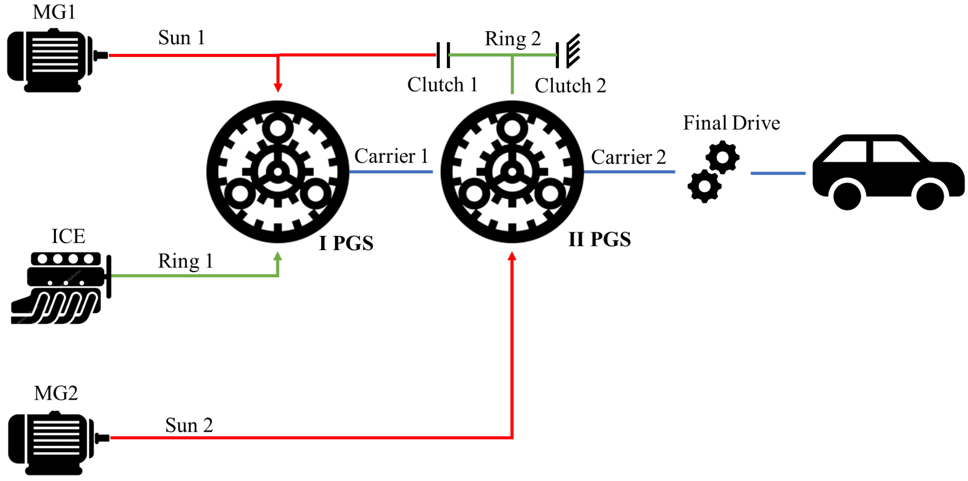
2. Multimode Hybrid Powertrain Model

The multimode hybrid powertrains considered within this paper are characterized by a number n of PGSs whose components (called nodes), i.e., the carrier, the ring, and the sun, can be linked together through q rigid connections and/or clutches. The number of the degrees of freedom (dofs) of the powertrain depends on the number of clutches engaged to activate a desired powertrain mode and it is equal to 2 n q . Each powertrain node can be driven by an actuator, i.e., the Internal Combustion Engine (ICE) and the electric Motors/Generators (MGs), as long as their number is equal or greater than the powertrain dofs.
The powertrain architecture selected for this paper is characterized by n = 2 PGSs, one rigid connection between their carriers and two clutches, as depicted in Figure 1.
The ICE and the first electric motor MG1 are considered always installed on the ring and the sun of the first PGS, respectively. The second electric motor MG2 and the transmission output shaft are connected to the sun and the carrier of the last PGS, respectively. A rigid connection constrains the carriers of the two PGS and the presence of two clutches enables the activation of the Input Split (clutch 2 engaged) or the Compound Split (clutch 1 engaged) hybrid modes (see Figure 2). In the Input Split mode, the secondary PGS behaves as an ordinary gear system, while primary PGS operates as a power split device. In the compound split mode, the power split occurs on both PGSs. In both cases, the number of powertrain dofs is always two ( n = 2 and q = 2).

2.1. Mathematical Model

The mathematical approach adopted to model the two-mode hybrid system is the same described by Tota et al. [36], where an automated routine is described to evaluate the dynamic equilibrium equations for a generic multimode powertrain architecture. The dynamic equilibrium of the two-mode hybrid system shown in Figure 1, with no clutches engaged, is expressed by (see also [36]):
A 0 x 0 = u 0
where the vector x 0 = [ ω ˙ c , 2 ω ˙ r , 1 ω ˙ s , 1 ω ˙ s , 2 ω ˙ c , 1 ω ˙ r , 2 F 1 F 2 ] T includes the angular acceleration of the two PGS carriers ( ω ˙ c , 1 , ω ˙ c , 2 ), suns ( ω ˙ s , 1 , ω ˙ s , 2 ), and rings ( ω ˙ r , 1 , ω ˙ r , 2 ) and the internal forces, F 1 and F 2 , exchanged between the ring and the pinions gears teeth of the first and the second PGS, respectively; u 0 = [ T l o a d T I C E T M G 1 T M G 2 0 0 0 0 ] T is the generalized torque vector, where T l o a d represents the equivalent vehicle motion resistance torque (see Equation (9)), T I C E is the torque applied by the Internal Combustion Engine (ICE) and T M G 1 and T M G 2 are the torques applied on the output shaft of the two Motors/Generators (MGs), respectively. The 8 × 8 matrix A 0 includes geometric and inertial parameters of the powertrain components (see also [36]):
A 0 = [ J o u t + J c , 2 0 0 0 0 0 0 r r , 2 + r s , 2 0 J I C E + J r , 1 0 0 0 0 r r , 1 0 0 0 J M G 1 + J s , 1 0 0 0 r s , 1 0 0 0 0 J M G 2 + J s , 2 0 0 0 r s , 2 0 0 0 0 J c , 1 0 r r , 1 + r s , 1 0 0 0 0 0 0 J r , 2 0 r r , 2 0 r r , 1 r s , 1 0 r r , 1 + r s , 1 0 0 0 r r , 2 + r s , 2 0 0 r s , 2 0 r r , 2 0 0 ]
where r r , 1 and r r , 2 are the ring gears radii and r s , 1 and r s , 2 the solar gears radii of the two PGSs, respectively; J r , 1 , J c , 1 , and J s , 1 are the torsional moments of inertia of the ring, the carrier and the solar gears of the first PGS, meanwhile J r , 2 , J c , 2 , and J s , 2 are the corresponding torsional moments of inertia of the second PGS; J I C E , J M G 1 , and J M G 2 represent the torsional moments of inertia of the ICE, the MG1 and MG2, respectively; J o u t = M R W 2 τ f 2 is the equivalent vehicle torsional moment of inertia where M is the vehicle mass, τ F is the transmission final drive ratio and R W the tire rolling radius.
The presence of rigid connections or clutch engagements between the component i and j of the two PGSs, modifies Equation (2) by summing up the j t h row to the i t h row and removing the j t h row, thus reducing the number of system equation. Due to the presence of a grounding clutch that links the k t h component of the two PGSs to the chassis, i.e., clutch 2 in Figure 1, the number of system equations in Equation (2) is further reduced by removing the k t h row. For both Input Split and Compound Split modes, the system in Equation (2) is reduced to (see also [36]):
A x = u
where x = [ ω ˙ c , 2 = ω ˙ c , 1 = ω ˙ o u t ω ˙ r , 1 = ω ˙ I C E ω ˙ s , 1 = ω ˙ M G 1 ω ˙ s , 2 = ω ˙ M G 1 F 1 F 2 ] T , u = [ T l o a d T I C E T M G 1 T M G 2 0 0 ] T and A is reduced to a 6 × 6 matrix. ω ˙ I C E , ω ˙ M G 1 , and ω ˙ M G 2 are the angular accelerations of the ICE, MG1 and MG2, respectively, meanwhile ω ˙ o u t is the transmission output angular acceleration. It is important to remark that this mathematical model does not include the transmission nonlinearities such as the gear backlashes, whose presence may affect the powertrain torsional dynamics in specific conditions [37,38].
Finally, by numerically inverting Equation (3) and considering the useful part of vector x , named in the following x = [ ω ˙ o u t ω ˙ I C E ω ˙ M G 1 ω ˙ M G 2 ] T , the inverse dynamic equation is obtained (see also [36]):
x = A T
where T = [ T l o a d T I C E T M G 1 T M G 2 ] T represents the torque distribution vector and A is a 4 × 4 matrix.

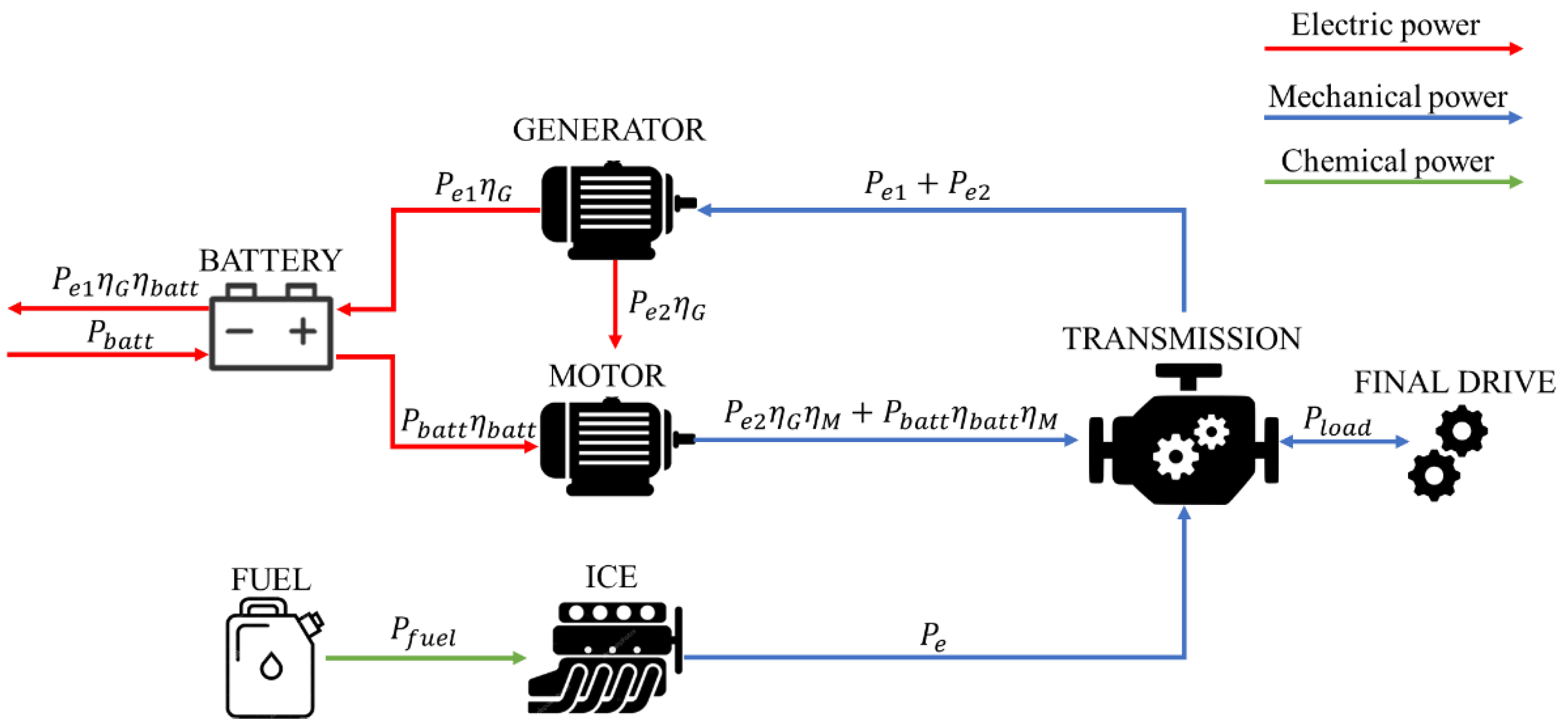
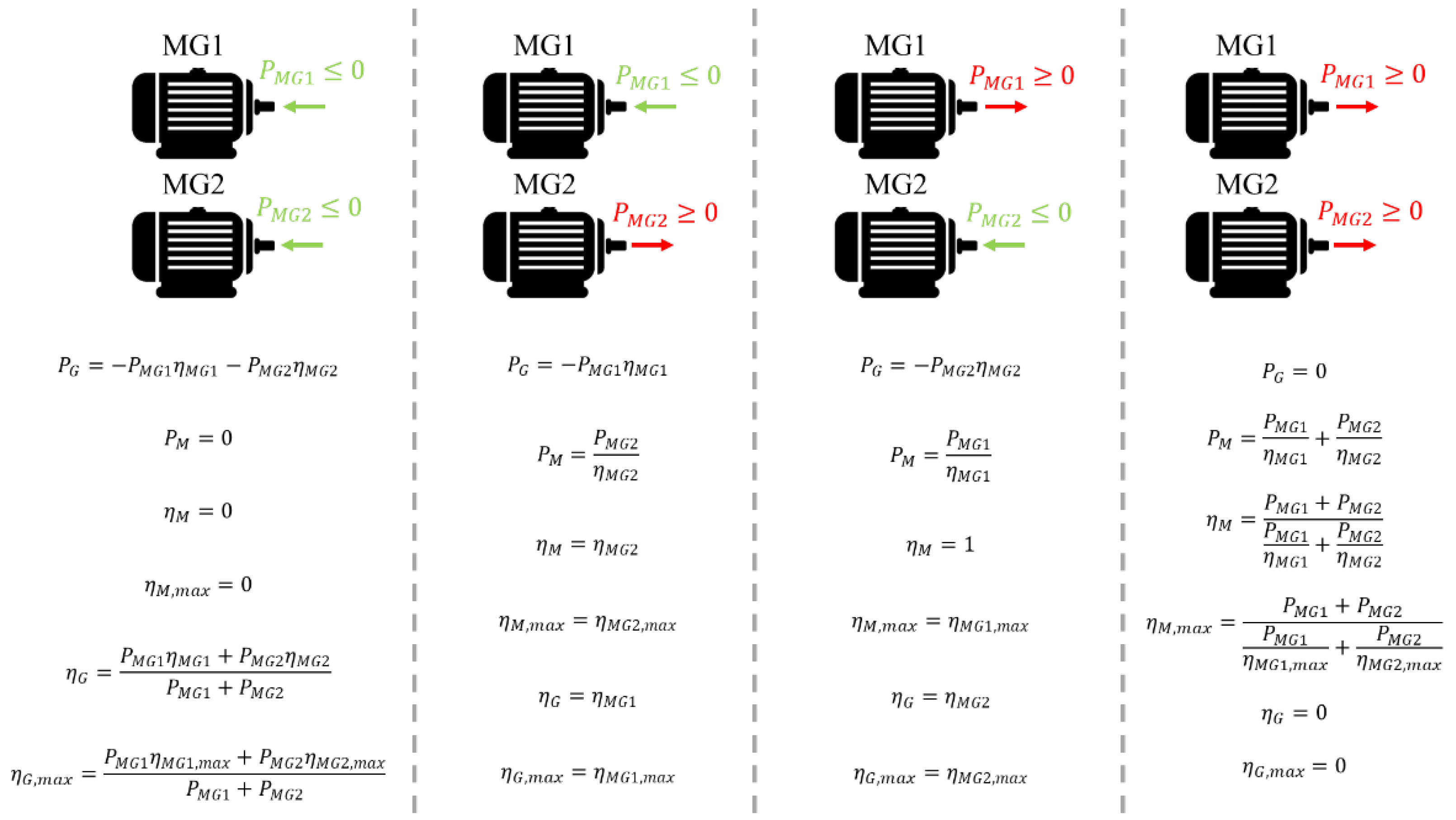
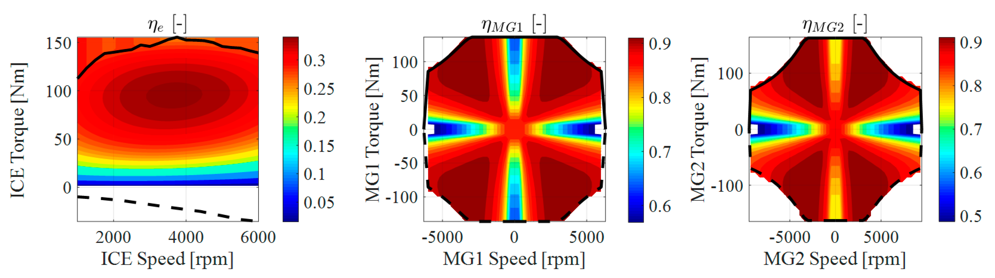
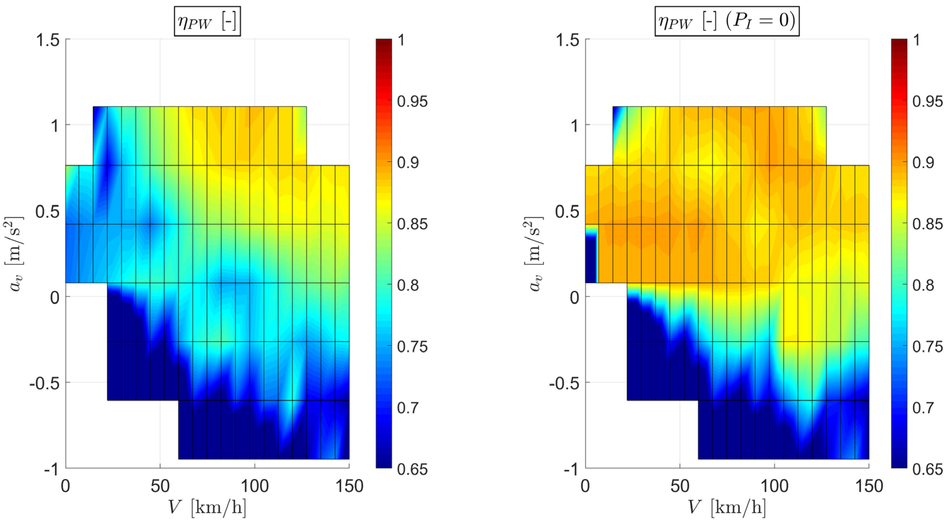
2.2. Power-Weighted Efficiency

The main task for the design of a hybrid powertrain is to search for the optimal torque distribution that satisfies a desired target. The approach adopted within this paper is to solve an energy loss minimization problem through the criterion of the power-weighted efficiency proposed by Zhang et al. [15]. The power-weighted efficiency η P W is evaluated as (see also [36]):
η P W = { P e 1 η G η b a t t η e , m a x η G , m a x + P e 2 η G η M η e , m a x η G , m a x η M , m a x + P e 3 η e , m a x + P b a t t η b a t t η M η M , m a x P f u e l   + P b a t t           f o r   P o u t , t r > 0 P e 1 η G η b a t t η e , m a x η G , m a x P f u e l   + P b a t t P e 2 η G η M P e 3 P b a t t η b a t t η M           f o r   P o u t , t r < 0
where P o u t , t r = T o u t , t r ω o u t represents the output power of the transmission with a transmission output torque T o u t , t r = T l o a d + ( I o u t + I c 1 + I c 2 ) ω ˙ o u t . In the definition of η P W , two energy sources are considered for satisfying the demanded power at the transmission output shaft: the battery and the fuel tank. The transmission efficiency is considered constant and equal to 1 within the paper, but its influence can be introduced to enhance the model as described by Galvagno [39].
In the generic scheme of Figure 3, P l o a d = T l o a d ω o u t is the loading power (positive or negative) meanwhile the engine output power P e = T e ω e can be split into three contributions: the engine power P e 1 that flows to the battery through the electric generators, the engine power P e 2 that flows to the electric motors through the generators and the engine power P e 3 that directly flows to the transmission output shaft ( P e 3 = P e P e 1 P e 2 ). A correct elaboration of engine power flow among P e 1 , P e 2 , and P e 3 requires the calculation of the electric power produced by the generators P G , and the electric power absorbed by the motors P M , as described in Figure 4.
If P G > P M , the additional generated electric power is used to charge the battery: P e 3 = P e P G η G , P e 2 η G = P M , P e 1 η G = P G P e 2 η G , and P b a t t = P e 1 η G η b a t t . Otherwise, if P G < P M , the battery energy is consumed: P b a t t = ( P M P G ) / η b a t t , P e 2 η G = P G , P e 1 η G = 0 , and P e 3 = P e P G η G . P b a t t and P f u e l represent the absorbed battery and fuel power, respectively. The battery efficiency η b a t t is evaluated by considering a simple circuit model (see the model described by Serrao et al. [17]):
η b a t t = 1 R b a t t I b a t t 2 V o c I b a t t
where I b a t t is the current through the battery circuit:
I b a t t = V o c V O C 2 4 R b a t t | P M P G | 2 R b a t t
The resistance of the battery circuit R b a t t and the battery open circuit voltage V o c are considered constant quantities with the hypothesis of a constant State of Charge (SOC = 70 % ) thus mostly relying on the electric energy stored in the battery (charge depleting).
The power-weighted efficiency allows to normalize the efficiencies from different type of power sources, without penalizing the engine operation even if the maximum ICE efficiency η e , m a x is much lower than η G , m a x , and η M , m a x .

3. Simulation Results
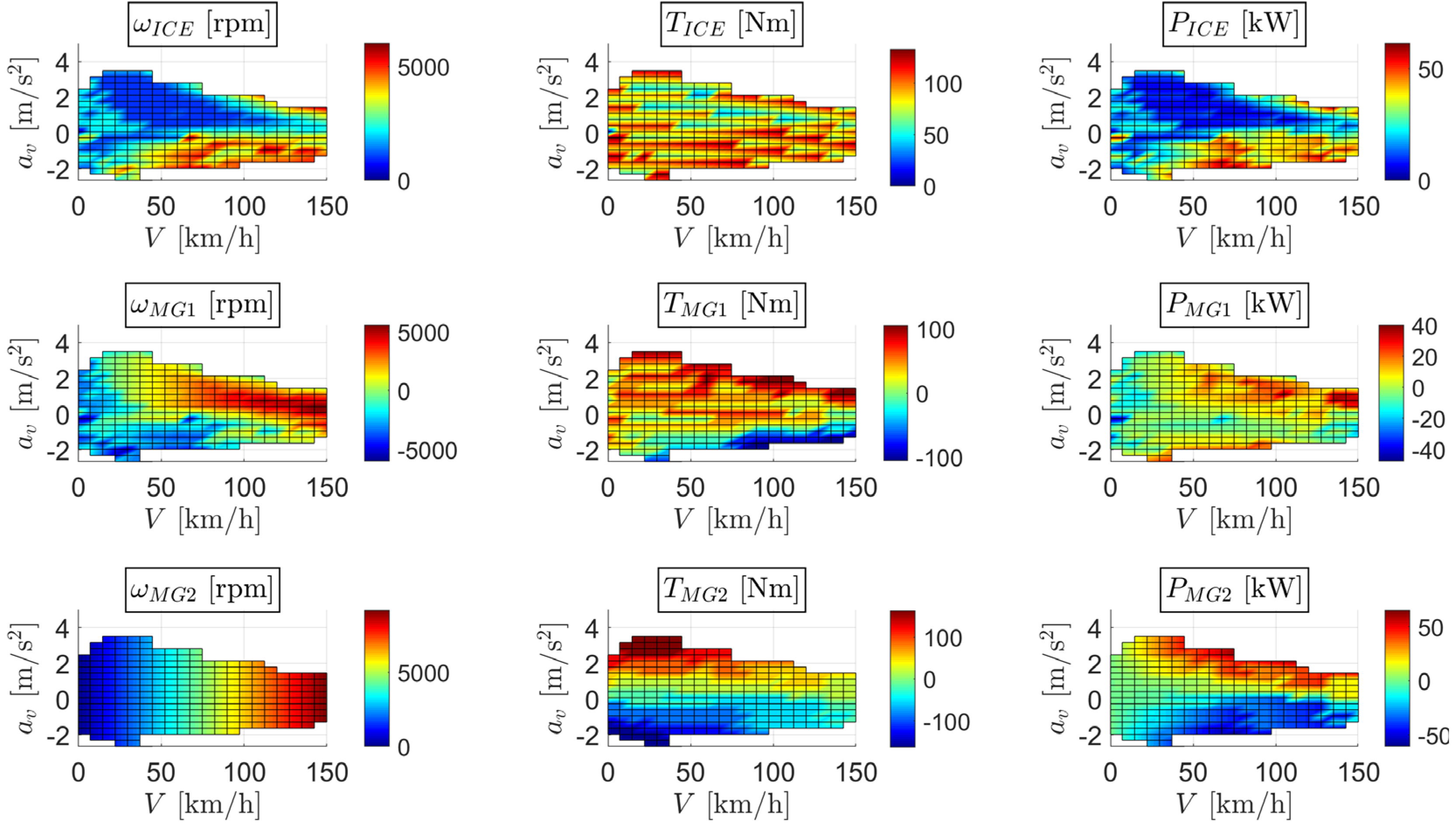
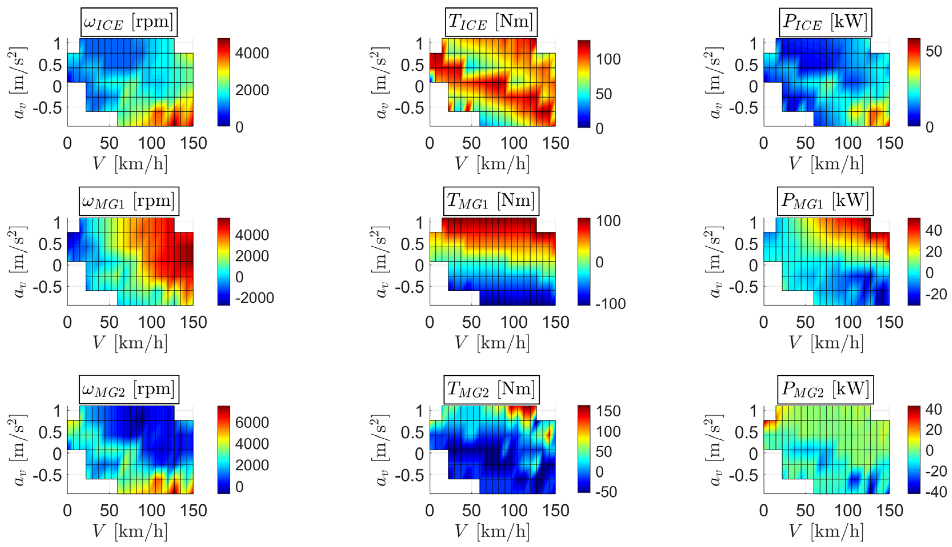
The definition of the power-weighted efficiency-based methodology is then evaluated by considering a set of vehicle and powertrain parameters, as reported in Table 1.
The ICE and the two MGs torque and efficiency characteristics are shown in Figure 5 and obtained from a commercial software usually adopted for modelling and simulating the behavior of hybrid vehicles. The MGs considered within the paper have the typical architecture adopted for hybrid vehicle powertrains, i.e., AC electric motors for the two-mode hybrid system from General Motors, whose steady-state power characteristics is a linear function of output shaft angular speed up to a specific speed limit above which the power saturates. The powertrain model presented in this paper does not include the effect of environment/external influences on powertrain components characteristics, but the methodology can be also extended to powertrain characteristics that are variable with external parameters, such as the temperature. An interesting experimental study is reported by Zhang et al. [40], where a complete energy flow test platform is designed and built to understand the influence of the environmental temperature on steady-state and transient plug-in hybrid electric vehicle energy transmissions at different states of charge. The powertrain architecture, shown in Figure 1, allows the activation of two modes: the Input Split mode, where the ring of the second PGS is connected to the chassis through the ground clutch 2, and the Compound Split mode, where the solar of the first PGS is linked to the ring of the second PGS through clutch 1.
To evaluate the efficacy of the methodology based on the power-weighted efficiency, a simulation setup is implemented in Matlab® environment, by considering the following procedure:
  • Selection of a longitudinal road slope α (first boundary condition);
  • Definition of an operating map among the whole set of admissible vehicle speed V and acceleration a v (second and third boundary conditions);
  • Calculation of transmission output angular speed ω o u t = τ F R W V and acceleration ω ˙ o u t = τ F R W a v ;
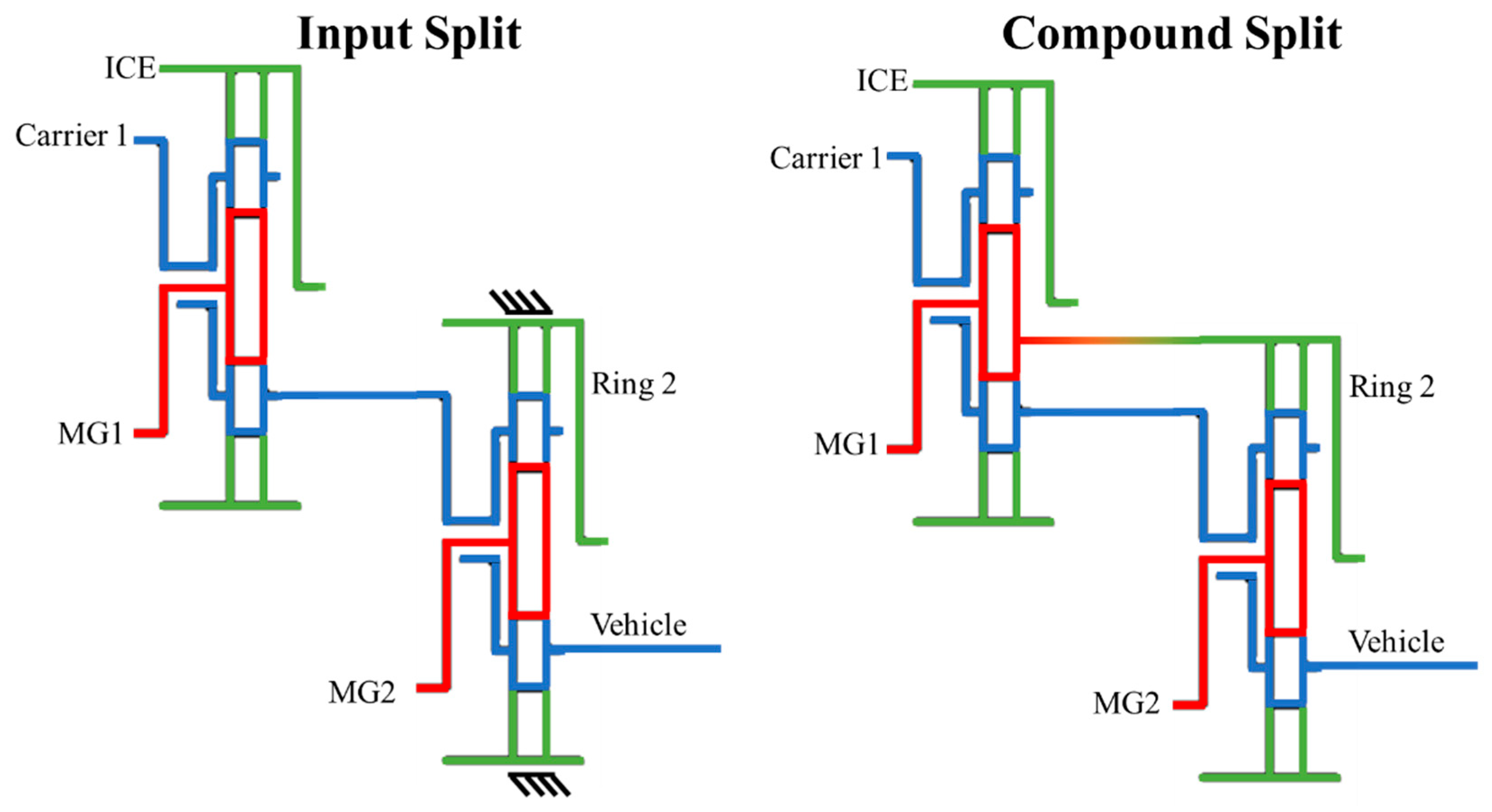
  • For 2 dofs powertrain configurations, such as the Input Split and the Compound Split modes, the angular speed of one actuator, i.e., the ICE speed ω I C E , is also varied within its admissible range;
  • The angular velocities of the remaining actuators, i.e., the two MGs angular speeds ω M G 1 and ω M G 2 , are calculated from the two PGS kinematic relations:
    { ω s , 1 r s , 1 + ω r , 1 r r , 1 = ω c , 1 ( r s , 1 + r r , 1 ) ω s , 2 r s , 2 + ω r , 2 r r , 2 = ω c , 2 ( r s , 2 + r r , 2 )
  • Evaluation of the transmission output resistance torque T l o a d :
    T l o a d = R W τ F ( M g f 0 cos α + M g sin α + 1 2 ρ C x S F V 2 )
    where f 0 is the constant tire rolling resistance coefficient, g is the gravitational acceleration, ρ is the air density, C x is the aerodynamic drag coefficient, S F the vehicle frontal area; It is important to remark that the vehicle braking is only entrusted to the electric generators, thus not considering the presence of a conventional hydraulic braking system (see the results presented by Galvagno et al. [41] for further details about hydraulic braking system modelling).
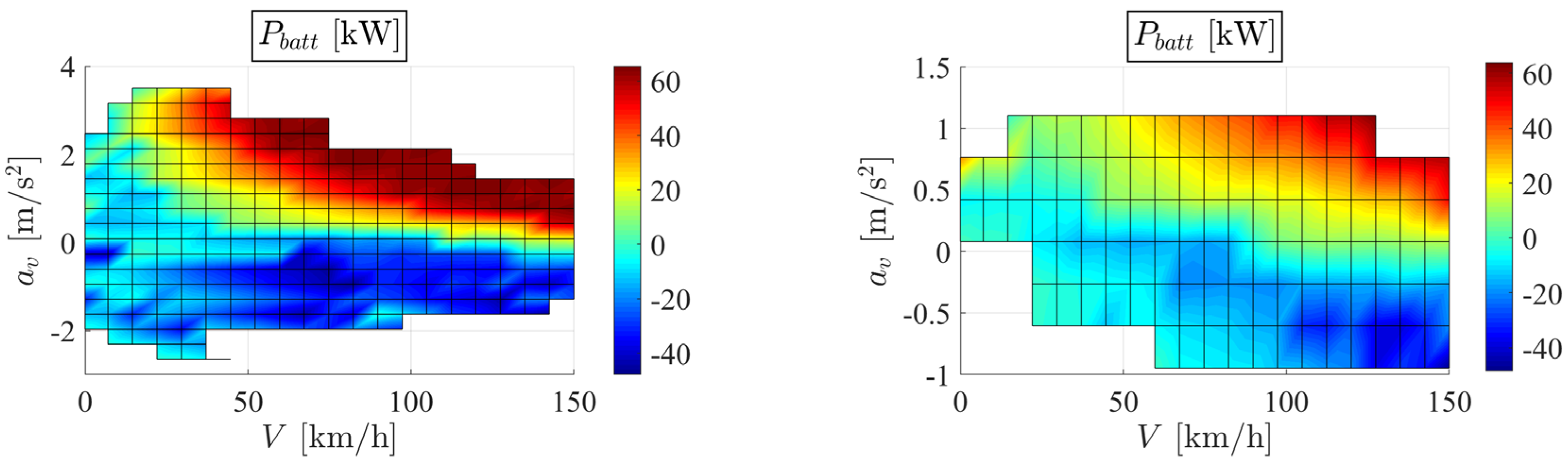
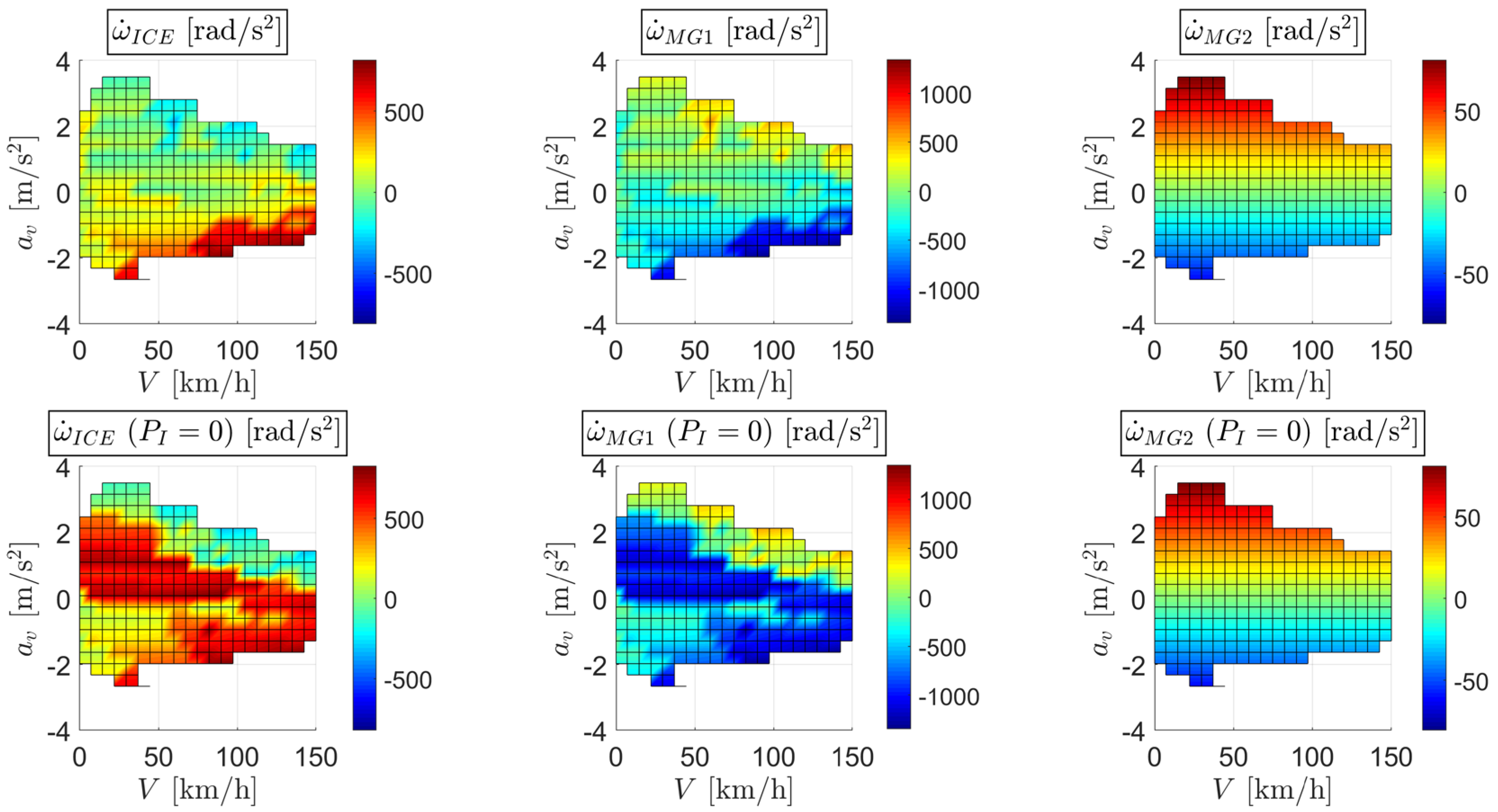
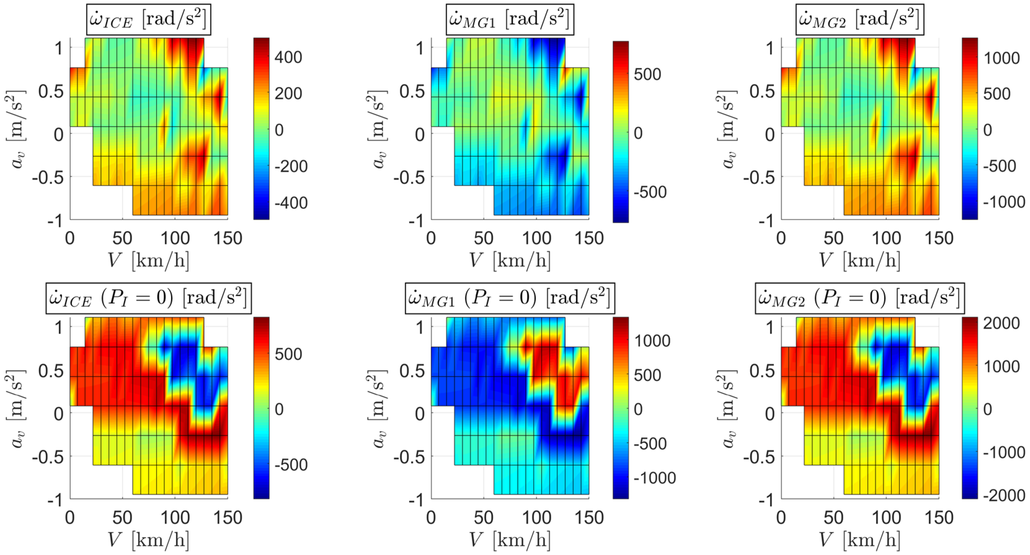
  • For each set of boundary conditions ( α , V , a v ), there exist infinite solutions for the distribution torque vector T , which satisfy Equation (4) (number of actuators larger than the number of dofs). By ranging the two MGs torques, T M G 1 and T M G 2 , between their minimum and maximum values at ω M G 1 and ω M G 2 , respectively, the system of equations in Equation (4) can be numerically discretized and solved to elaborate the resulting ICE torque T I C E and angular acceleration ω ˙ I C E . The angular accelerations of the two MGs, ω ˙ M G 1 and ω ˙ M G 2 , are then calculated from ω ˙ o u t and ω ˙ I C E through the PGS kinematic relations in Equation (8). Finally, the procedure computes a discrete number of solutions, identified by a combination of ω I C E , T M G 1 , and T M G 2 , that satisfy the boundary conditions of road slope, vehicle speed, and acceleration. An admissible solution is accepted, to calculate the output power and efficiency of each actuator, only if the following constraints are satisfied:
    { ω I C E , m i n ω I C E ω I C E , m a x ω M G 1 , m i n ω M G 1 ω M G 1 , m a x ω M G 2 , m i n ω M G 2 ω M G 2 , m a x { 0 T I C E T I C E , m a x ( ω I C E ) | T M G 1 | T M G 1 , m a x ( ω M G 1 ) | T M G 2 | T M G 2 , m a x ( ω M G 2 ) { 0 P I C E P I C E , m a x ( ω I C E ) | P M G 1 | P M G 1 , m a x ( ω M G 1 ) | P M G 2 | P M G 2 , m a x ( ω M G 2 ) P b a t t , m i n P b a t t P b a t t , m a x
The classic definition of the power-weighted efficiency in Equation (5) is only valid for steady-state working conditions of the powertrain components (negligible influence of inertial parameters) and cannot be directly adopted as discriminant factor to select the optimal combination of ω I C E , T M G 1 , and T M G 2 , for a given road slope, vehicle speed, and acceleration. Consequently, a modified version of power-weighted efficiency, η P W p , is defined to penalize the admissible solutions with a high inertial power P I of the powertrain components:
η P W = { P e 1 η G η b a t t η e , m a x η G , m a x + P e 2 η G η M η e , m a x η G , m a x η M , m a x + P e 3 η e , m a x + P b a t t η b a t t η M η M , m a x P f u e l   + P b a t t + | P I |           f o r   P o u t , t r > 0 P e 1 η G η b a t t η e , m a x η G , m a x P f u e l   + P b a t t P e 2 η G η M P e 3 P b a t t η b a t t η M + | P I |           f o r   P o u t , t r < 0
where the inertial power is defined as:
P I = i = 1 2 ( J c , i ω ˙ c , i ω c , i + J s , i ω ˙ s , i ω s , i + J r , i ω ˙ r , i ω r , i ) + J I C E ω ˙ I C E ω I C E + J M G 1 ω ˙ M G 1 ω M G 1 + J M G 2 ω ˙ M G 2 ω M G 2
The inertial power enters as a penalty factor in the definition of the power-weighted efficiency but it physically represents the variation of kinetic energy accumulated or released to equilibrate the power distribution of the transmission in Figure 3: P I = P e 2 η G η M + P e 3 + μ P b a t t η b a t t η M P l o a d . The admissible solution with a combination of ω I C E , T M G 1 and T M G 2 that guarantees the lowest value of η P W p is then selected as the optimal choice, in terms of actuators power distribution, for that boundary conditions of road slope, vehicle speed, and acceleration. The optimal solution is then represented through 2D maps reporting the value of speed, torque and power for each powertrain component as function of vehicle speed and acceleration, calculated for a fixed road slope, as shown in Figure 6 for the Input Split mode and α = 0 .
If there is not even one combination of ω I C E , T M G 1 , and T M G 2 that satisfies the whole set of physical constraints described by Equation (10), then there is no solution for that boundary conditions of road slope, vehicle speed and acceleration and the corresponding point on the 2D map is not displayed.

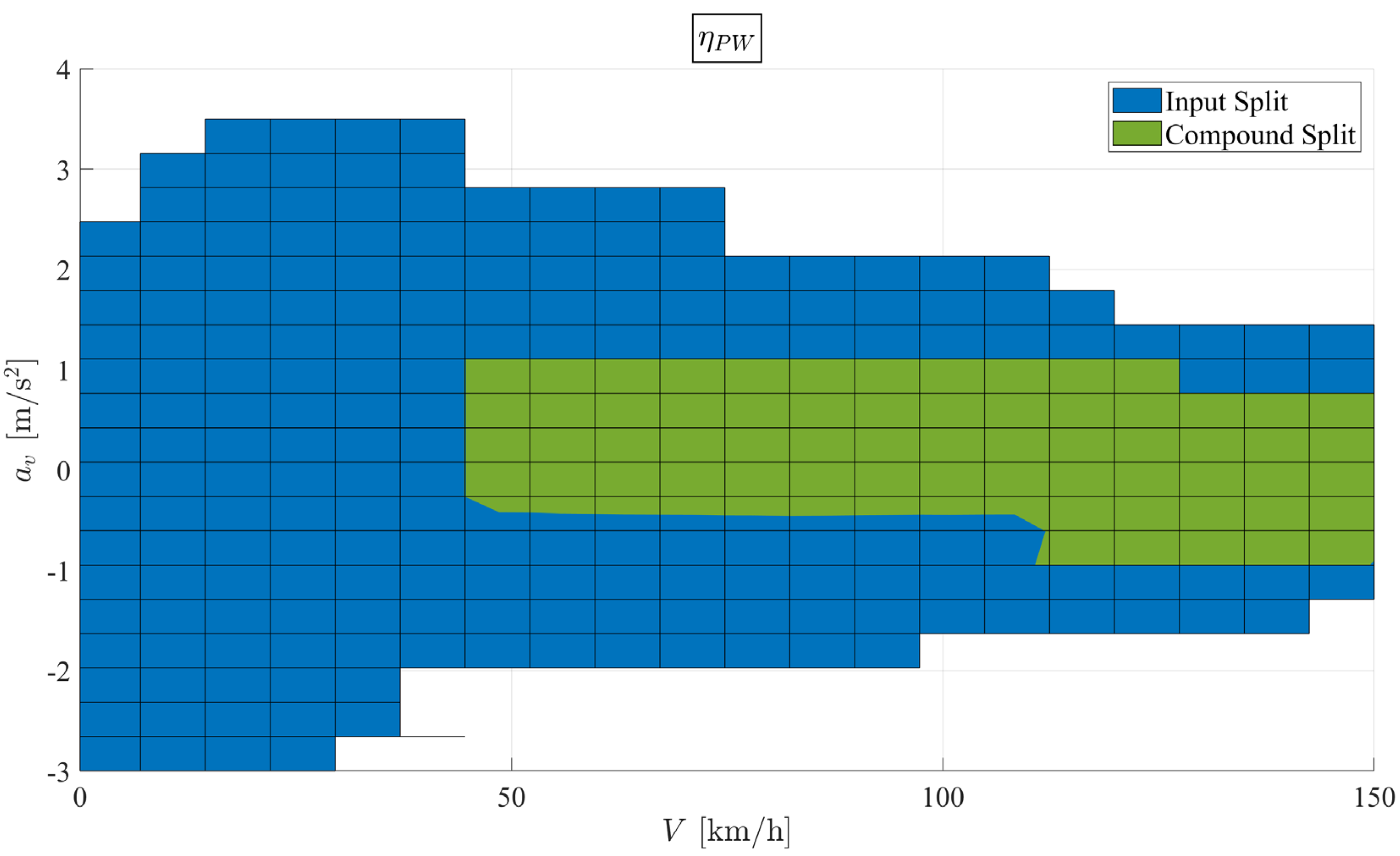
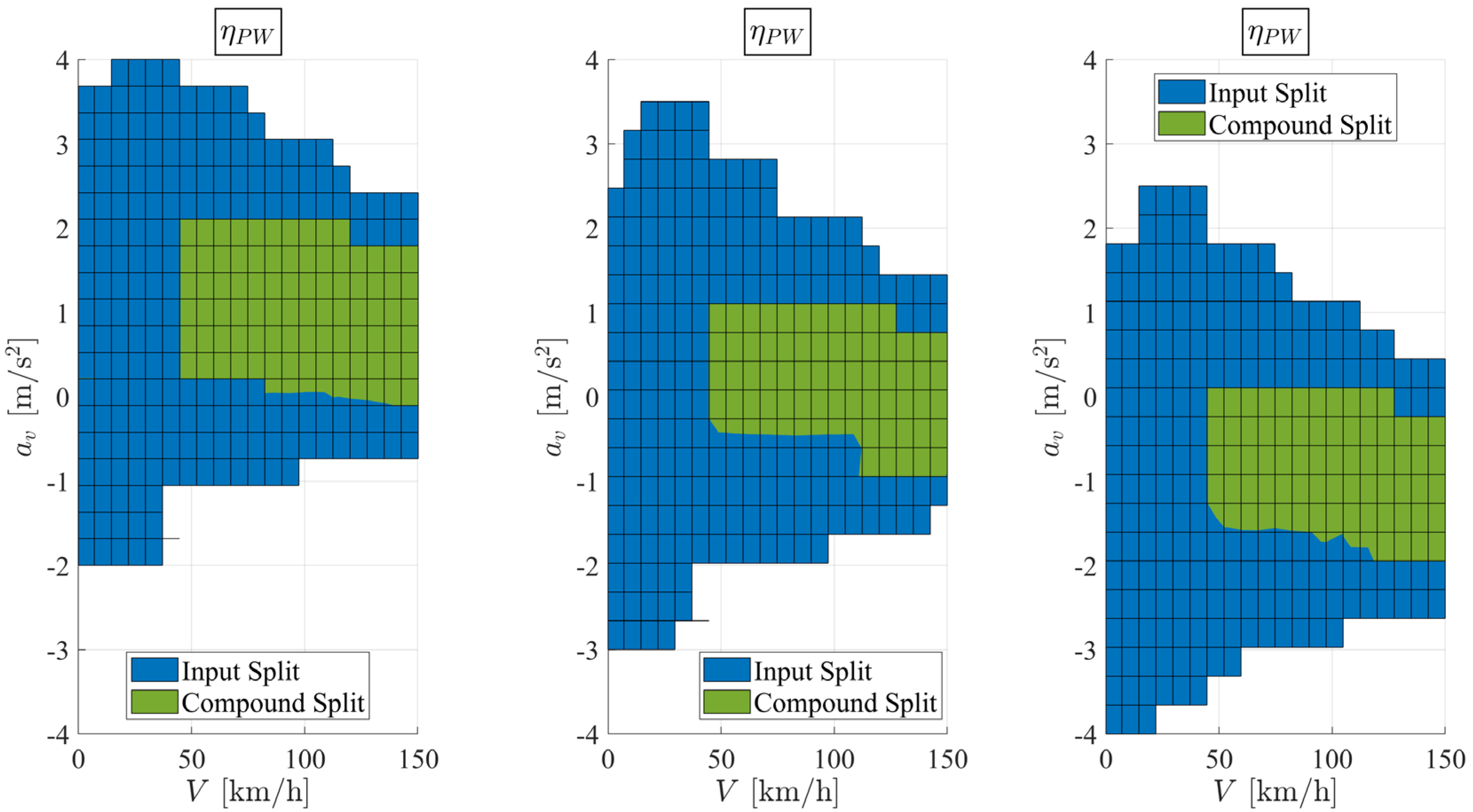
3.1. Powertrain Mode Selection

The concept of power-weighted efficiency represents an important discriminant factor to evaluate and select the most suitable powertrain mode and satisfy the minimum energy consumption criterion, for each vehicle operating condition (vehicle speed and acceleration, road slope). In particular, the hybrid system analyzed within this paper, whose architecture is depicted in Figure 1, can work with the Input Split or the Compound Split modes whose resulting maps, for a fixed road slope α = 0 , are reported in Figure 6 and Figure 7, respectively.
The first main difference between the two modes is that the Input Split mode can manage higher vehicle accelerations while the Compound Split mode is able to run up the vehicle at higher speeds. All maps are obtained by limiting the maximum speed to 150 km/h. The output power requested to the three actuators at the maximum speed with the Compound Split mode is lower than the corresponding value for the Input Split mode, since the vehicle can reach higher velocities with the Compound Split mode. For high request of output power, in terms of vehicle speed and accelerations, the MG1 tends to work mainly as an electric motor during both Input Split and Compound Split modes. The MG2 operating range is fully exploited during the Input Split mode, meanwhile its output power is nearly for the Compound Split mode. The ICE mainly provides high torque at lower engine speeds, thus working within its most efficient condition. The torque and angular speed maps of each actuator are overlapped on their corresponding efficiency characteristics, as shown in Figure 8, thus proving that the power-weighted efficiency methodology tends to bind the working conditions within a high efficiency range.
The procedure here proposed relies on the minimum energy consumption criterion, which leads to a charge depleting of the battery. Indeed, a large contribution of battery power, shown in Figure 9 together with ICE fuel consumption map, is requested during high speed acceleration.
Finally, the selection between Input Split and Compound Split modes is carried out by considering the one that guarantees the highest value of power-weighted efficiency in the whole range of the vehicle operating condition, as shown in Figure 10.

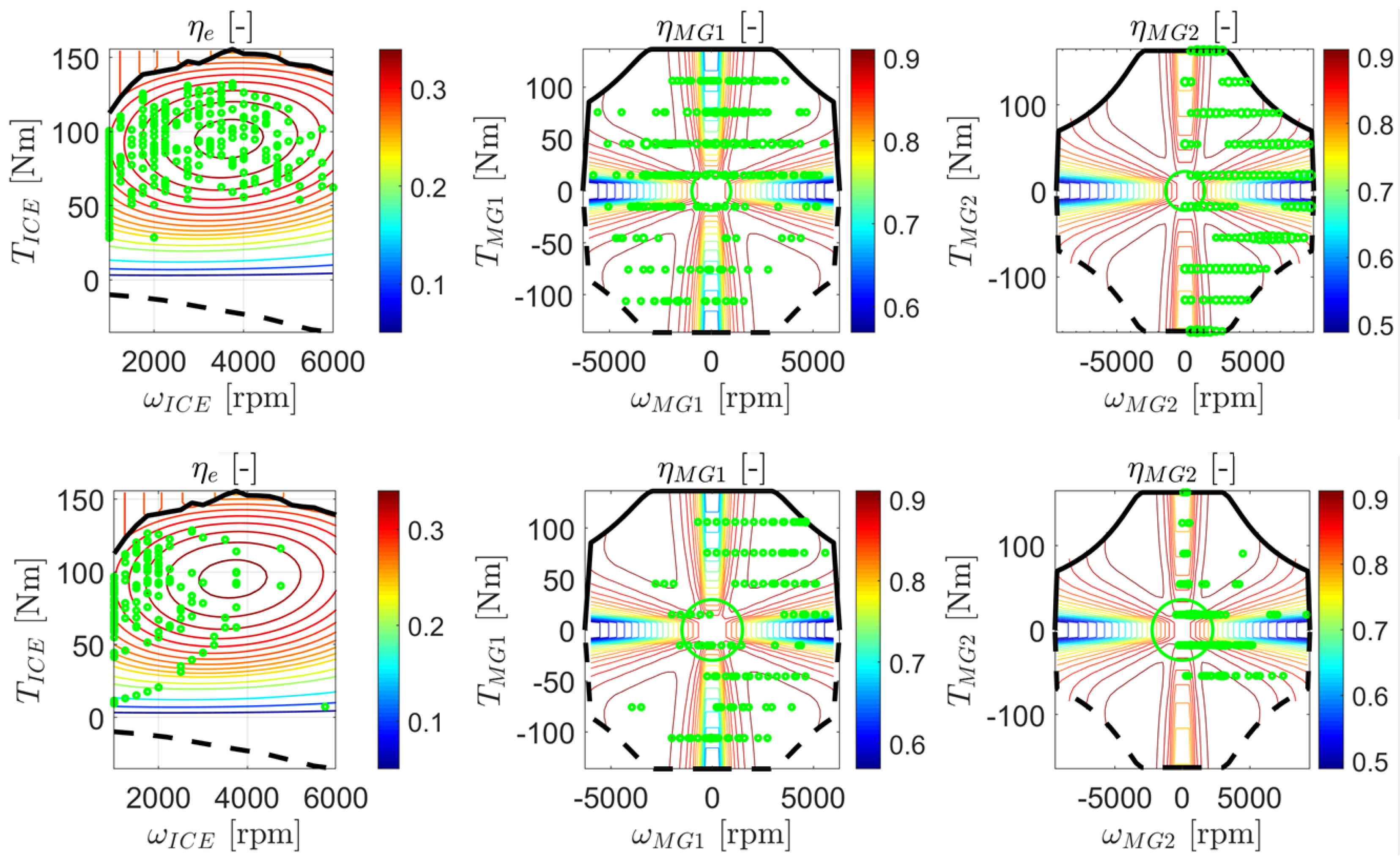
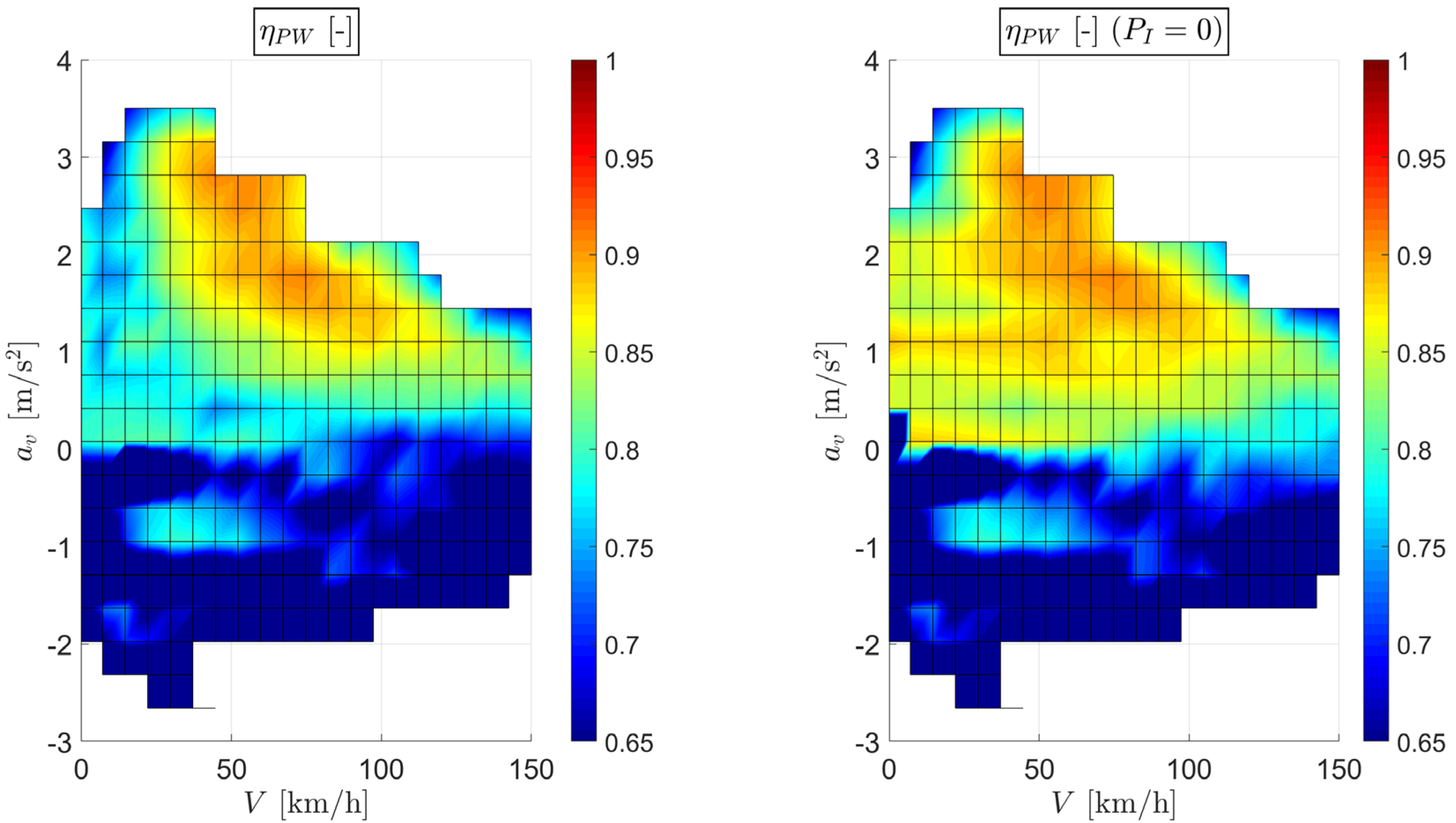
3.2. Effect of the Inertial Penalty Factor

The main original contribution of this paper is the introduction of the inertial penalty factor P I into the definition of the dynamic power-weighted efficiency to discriminate the most suitable torque distribution. This contribution allows to penalize all the admissible solutions where a considerable amount of input power would be exploited to accelerate one or more powertrain components instead of accelerating the vehicle and/or overcome its motion resistances. To proof the efficacy of this effect, the resulting maps of ICE, MG1 and MG2 angular accelerations are compared against the case where the actuators torque distribution is chosen based on the lower power-weighted efficiency η P W instead of η P W p . The simulation results, obtained for a null road slope, are shown in Figure 11.
The color bar scale has been adapted for each map, in order to center the null angular acceleration within a green zone between the maximum (red zone) and the minimum (blue zone) angular accelerations for each powertrain actuator. Both red and blue zones are considered as undesirable since part of the input power would be wasted to increase the kinetic energy of one of the three actuators inertia. The presence of the penalty factor P I automatically discards the admissible but undesirable solutions by reducing their corresponding η P W p , as it is evident by the larger green zone for the top maps compared to the bottom ones, especially for ICE and MG1. Instead, MG2 angular acceleration is not affected by the introduction of the penalty factor since it is kinematically correlated to the vehicle acceleration a v for the Input Split mode (clutch 2 engaged).
A drawback correlated to the penalty factor is that the resulting map of the power-weighted efficiency η P W assumes a different shape, as shown in Figure 12: when the penalty factor is activated there are some regions where the power-weighted efficiency is smaller.
The penalty factor discharges some admissible solutions with higher power-weighted efficiency values since it does not fully exploit the kinetic energy stored within the powertrain components. However, this drawback does not affect in a significant way the power-weighted efficiency, as proved by Figure 12. A similar consideration can be drawn with the Compound Split mode as reported by Figure 13 and Figure 14.

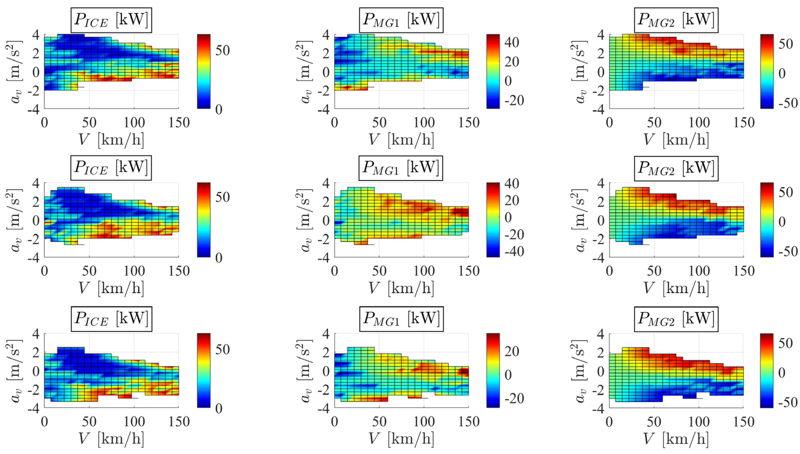
3.3. Road Slope Influence

The last analysis presented to validate and emphasize the potential of the power-weighted efficiency toolbox, is represented by the influence of the road slope on the map generation as well as on the powertrain mode selection. The map obtained on a flat road is compared against the uphill ( α = 10 % ) and downhill ( α = 10 % ) scenarios; the correspondent power flow distribution among the three actuators is reported in Figure 15.
Passing from downhill to uphill conditions, all maps tend to shift toward lower accelerations due to the presence of the road inclination. The MG1 mostly works as an electric generator, while MG2 provides extra power during extreme accelerations maneuvers. The presence of a road inclination (positive or negative) also contributes to modify the acceleration threshold for switching between Input Split and Compound Split modes, as shown in Figure 16, with the speed threshold kept fixed at 50 km/h.

4. Conclusions

The paper aims at providing a straightforward and clear procedure to model and select the suitable powertrain mode and the operating condition for each actuator, based on the power-weighted efficiency concept. The main conclusions can be summarized in the following points:
  • Hybrid powertrains can be controlled by actuators whose nature is extremely different in terms of efficiency and dynamic characteristics. An energy management strategy relying only on the individual efficiency map of each actuator does not provide a satisfying power distribution, since it limits or completely excludes the actuators with lower maximum efficiency, i.e., the ICE. The power-weighted efficiency provides a unique parameter that normalize the overall efficiency contribution of each actuator based on the power flow requested during a specific vehicle working condition which is not correlated to a specific driving cycle.
  • There are multiple solutions, in terms of actuator torque distribution, for a given set of boundary conditions in terms of road slope, vehicle speed, and acceleration. The power-weighted efficiency could represent a valid parameter to discriminate and select the best working map for each actuator that satisfies the minimum energy loss principle. However, this solution would not prevent from undesirable working conditions where part of the power is addressed to accelerate or decelerate one or more powertrain components. Aiming at minimizing the variation of the powertrain kinetic energy, a penalty factor is introduced into the definition of the power-weighted efficiency that always guarantees high efficiency, though slightly lower than the maximum possible value, with a more targeted power flow towards the vehicle and/or the battery.
  • This methodology also considers the effect of the road inclination, which modifies the admissible vehicle acceleration range. This approach is able to regulate the operative condition of each actuator and to switch the two electric machine modes between generator and motor, thus taking advantage or compensating the road inclination influence.
This paper represents an initial step towards the validation of the effectiveness of the presented methodology which would require a further investigation in terms of comparison against other conventional strategies as well as a fair experimental campaign to assess the efficiency and dynamic performance of the new formulation, based on the power-weighted efficiency.

Author Contributions

Conceptualization, A.T., E.G., A.V., and M.V.; Data curation, A.T.; Formal analysis, A.T.; Methodology, A.T., E.G., A.V., and M.V.; Software, A.T., E.G.; Supervision, M.V.; Writing—original draft, A.T.; Writing—review and editing, E.G., A.V., L.D., and M.V. All authors have read and agreed to the published version of the manuscript.

Funding

This research received no external funding.

Institutional Review Board Statement

Not applicable.

Informed Consent Statement

Not applicable.

Data Availability Statement

Not applicable.

Conflicts of Interest

The authors declare no conflict of interest.

References

  1. Xu, N.; Kong, Y.; Chu, L.; Ju, H.; Yang, Z.; Xu, Z.; Xu, Z. Towards a smarter energy management system for hybrid vehicles: A comprehensive review of control strategies. Appl. Sci. 2019, 9, 2026. [Google Scholar] [CrossRef] [Green Version]
  2. Jung, H. Fuel economy of plug-in hybrid electric and hybrid electric vehicles: Effects of vehicle weight, hybridization ratio and ambient temperature. World Electr. Veh. J. 2020, 11, 31. [Google Scholar] [CrossRef] [Green Version]
  3. Tran, D.D.; Vafaeipour, M.; El Baghdadi, M.; Barrero, R.; Van Mierlo, J.; Hegazy, O. Thorough state-of-the-art analysis of electric and hybrid vehicle powertrains: Topologies and integrated energy management strategies. Renew. Sustain. Energy Rev. 2020, 119, 109596. [Google Scholar] [CrossRef]
  4. Jochem, P.; Babrowski, S.; Fichtner, W. Assessing CO2 emissions of electric vehicles in Germany in 2030. Transp. Res. Part A Policy Pract. 2015, 78, 68–83. [Google Scholar] [CrossRef] [Green Version]
  5. Burch, I.; Gilchrist, J. Survey of Global Activity to Phase out Internal Combustion Engine Vehicles; Center of Climate Protection: Santa Rosa, CA, USA, 2018. [Google Scholar]
  6. Cirimele, V.; Dimauro, L.; Repetto, M.; Bonisoli, E. Multi-objective optimisation of a magnetic gear for powertrain applications. Int. J. Appl. Electromagn. Mech. 2019, 60, S25–S34. [Google Scholar] [CrossRef]
  7. Mi, C.; Masrur, M.A. Hybrid Electric Vehicles: Principles and Applications with Practical Perspectives; John Wiley & Sons: Hoboken, NJ, USA, 2017. [Google Scholar]
  8. Ehsani, M.; Gao, Y.; Longo, S.; Ebrahimi, K.M. Modern Electric, Hybrid Electric, and Fuel Cell Vehicles; CRC Press: Boca Raton, FL, USA, 2018. [Google Scholar]
  9. Chan, C.C. The state of the art of electric, hybrid, and fuel cell vehicles. Proc. IEEE 2007, 95, 704–718. [Google Scholar] [CrossRef]
  10. Johri, R.; Filipi, Z. Optimal energy management of a series hybrid vehicle with combined fuel economy and low-emission objectives. Proc. Inst. Mech. Eng. Part D J. Automob. Eng. 2014, 228, 1424–1439. [Google Scholar] [CrossRef]
  11. Dorri, M.; Shamekhi, A.H. Design and optimization of a new control strategy in a parallel hybrid electric vehicle in order to improve fuel economy. Proc. Inst. Mech. Eng. Part D J. Automob. Eng. 2011, 225, 747–759. [Google Scholar] [CrossRef]
  12. Bole, B.; Coogan, S.; Cubero-Ponce, C.; Edwards, D.; Melsert, R.; Taylor, D. Energy management control of a hybrid electric vehicle with two-mode electrically variable transmission. In Proceedings of the EVS26 International Battery, Hybrid and Fuel Cell Electric Vehicle Symposium, Los Angeles, CA, USA, 6–9 May 2012. [Google Scholar]
  13. Galvagno, E.; Vigliani, A.; Velardocchia, M. Transient response and frequency domain analysis of an electrically variable transmission. Adv. Mech. Eng. 2018, 10, 1687814018776182. [Google Scholar] [CrossRef]
  14. Zhang, X.; Peng, H.; Sun, J. A near-optimal power management strategy for rapid component sizing of multimode power split hybrid vehicles. IEEE Trans. Control Syst. Technol. 2014, 23, 609–618. [Google Scholar] [CrossRef]
  15. Zhang, X.; Eben Li, S.; Peng, H.; Sun, J. Efficient exhaustive search of power-split hybrid powertrains with multiple planetary gears and clutches. J. Dyn. Syst. Meas. Control 2015, 137, 121006. [Google Scholar] [CrossRef]
  16. Zhuang, W.; Zhang, X.; Ding, Y.; Wang, L.; Hu, X. Comparison of multi-mode hybrid powertrains with multiple planetary gears. Appl. Energy 2016, 178, 624–632. [Google Scholar] [CrossRef]
  17. Serrao, L.; Onori, S.; Rizzoni, G. A comparative analysis of energy management strategies for hybrid electric vehicles. J. Dyn. Syst. Meas. Control 2011, 133, 031012. [Google Scholar] [CrossRef] [Green Version]
  18. Lee, H.; Song, C.; Kim, N.; Cha, S.W. Comparative analysis of energy management strategies for HEV: Dynamic programming and reinforcement learning. IEEE Access 2020, 8, 67112–67123. [Google Scholar] [CrossRef]
  19. Hofman, T.; Steinbuch, M.; Van Druten, R.; Serrarens, A. Rule-based energy management strategies for hybrid vehicles. Int. J. Electr. Hybrid Veh. 2007, 1, 71–94. [Google Scholar] [CrossRef]
  20. Sorrentino, M.; Rizzo, G.; Arsie, I. Analysis of a rule-based control strategy for on-board energy management of series hybrid vehicles. Control Eng. Pract. 2011, 19, 1433–1441. [Google Scholar] [CrossRef]
  21. Guercioni, G.R.; Galvagno, E.; Tota, A.; Vigliani, A. Adaptive Equivalent Consumption Minimization Strategy With Rule-Based Gear Selection for the Energy Management of Hybrid Electric Vehicles Equipped with Dual Clutch Transmissions. IEEE Access 2020, 8, 190017–190038. [Google Scholar] [CrossRef]
  22. Sciarretta, A.; Back, M.; Guzzella, L. Optimal control of parallel hybrid electric vehicles. IEEE Trans. Control Syst. Technol. 2004, 12, 352–363. [Google Scholar] [CrossRef]
  23. Huang, Y.; Wang, H.; Khajepour, A.; He, H.; Ji, J. Model predictive control power management strategies for HEVs: A review. J. Power Sources 2017, 341, 91–106. [Google Scholar] [CrossRef]
  24. Li, X.; Han, L.; Liu, H.; Wang, W.; Xiang, C. Real-time optimal energy management strategy for a dual-mode power-split hybrid electric vehicle based on an explicit model predictive control algorithm. Energy 2019, 172, 1161–1178. [Google Scholar] [CrossRef]
  25. Xie, S.; Hu, X.; Qi, S.; Tang, X.; Lang, K.; Xin, Z.; Brighton, J. Model predictive energy management for plug-in hybrid electric vehicles considering optimal battery depth of discharge. Energy 2019, 173, 667–678. [Google Scholar] [CrossRef]
  26. Li, J.; Zhou, Q.; He, Y.; Shuai, B.; Li, Z.; Williams, H.; Xu, H. Dual-loop online intelligent programming for driver-oriented predict energy management of plug-in hybrid electric vehicles. Appl. Energy 2019, 253, 113617. [Google Scholar] [CrossRef] [Green Version]
  27. Delprat, S.; Lauber, J.; Guerra, T.M.; Rimaux, J. Control of a parallel hybrid powertrain: Optimal control. IEEE Trans. Veh. Technol. 2004, 53, 872–881. [Google Scholar] [CrossRef]
  28. Kim, N.; Cha, S.; Peng, H. Optimal control of hybrid electric vehicles based on Pontryagin’s minimum principle. IEEE Trans. Control Syst. Technol. 2010, 19, 1279–1287. [Google Scholar]
  29. Galvagno, E.; Guercioni, G.; Rizzoni, G.; Velardocchia, M.; Vigliani, A. Effect of engine start and clutch slip losses on the energy management problem of a hybrid DCT powertrain. Int. J. Automot. Technol. 2020, 21, 953–969. [Google Scholar] [CrossRef]
  30. Guercioni, G.R.; Vigliani, A. Gearshift control strategies for hybrid electric vehicles: A comparison of powertrains equipped with automated manual transmissions and dual-clutch transmissions. Proc. IMechE Part D J. Automob. Eng. 2019, 233, 2761–2779. [Google Scholar] [CrossRef]
  31. Finesso, R.; Misul, D.; Spessa, E.; Venditti, M. Optimal design of power-split hevs based on total cost of ownership and CO2 emission minimization. Energies 2018, 11, 1705. [Google Scholar] [CrossRef] [Green Version]
  32. Chen, Z.; Mi, C.C.; Xiong, R.; Xu, J.; You, C. Energy management of a power-split plug-in hybrid electric vehicle based on genetic algorithm and quadratic programming. J. Power Sources 2014, 248, 416–426. [Google Scholar] [CrossRef]
  33. Zhang, X.; Peng, H.; Sun, J. A near-optimal power management strategy for rapid component sizing of power split hybrid vehicles with multiple operating modes. In 2013 American Control Conference; IEEE: Washington, DC, USA, 2013; pp. 5972–5977. [Google Scholar]
  34. Grewe, T.M.; Conlon, B.M.; Holmes, A.G. Defining the General Motors 2-Mode Hybrid Transmission (No. 2007-01-0273); SAE Technical Paper; SAE World Congress & Exhibition: Warrendale, PA, USA, 2007. [Google Scholar]
  35. Tinelli, V.; Galvagno, E.; Velardocchia, M. Dynamic Analysis and Control of a Dual Mode Electrically Variable Transmission. In IFToMM World Congress on Mechanism and Machine Science; Springer: Cham, Switzerland, 2019; pp. 3731–3740. [Google Scholar]
  36. Tota, A.; Galvagno, E.; Velardocchia, M. On the Power-weighted Efficiency of Multimode Powertrains: A case study on a Two-Mode Hybrid System. In IFToMM and Sustainable Development Goals—Proceedings of the First I4SDG Workshop; Mechanisms and Machine Science; Springer: Cham, Switzerland, 2021; Volume 108. [Google Scholar] [CrossRef]
  37. Guercioni, G.R.; Galvagno, E.; Tota, A.; Vigliani, A.; Zhao, T. Driveline Backlash and Half-Shaft Torque Estimation for Electric Powertrains Control (No. 2018-01-1345); SAE Technical Paper; SAE World Congress & Exhibition: Warrendale, PA, USA, 2018. [Google Scholar]
  38. Galvagno, E.; Tota, A.; Velardocchia, M.; Vigliani, A. Enhancing Transmission NVH Performance through Powertrain Control Integration with Active Braking System (No. 2017-01-1778); SAE Technical Paper; SAE World Congress & Exhibition: Warrendale, PA, USA, 2017. [Google Scholar]
  39. Galvagno, E. Epicyclic gear train dynamics including mesh efficiency. Int. J. Mech. Control 2010, 11, 41–47. [Google Scholar]
  40. Zhang, Y.; Yuan, X.; Duan, L.; Xu, Y.; Lan, F. Environmental temperature effects on the energy flow of plug-in hybrid electric vehicles. J. Power Sources 2021, 506, 230–231. [Google Scholar] [CrossRef]
  41. Galvagno, E.; Tota, A.; Vigliani, A.; Velardocchia, M. Pressure following strategy for conventional braking control applied to a HIL test bench. SAE Int. J. Passeng. Cars-Mech. Syst. 2017, 10, 721–727. [Google Scholar] [CrossRef]
Figure 1. Scheme of the powertrain architecture in the two-mode hybrid system.
Applsci 11 11752 g001
Figure 2. Scheme of the two powertrain modes: Input Split (left) and Compound Split (right).
Applsci 11 11752 g002
Figure 3. Generic scheme of the power flow for a hybrid powertrain.
Applsci 11 11752 g003
Figure 4. Absorbed and generated electric power P M and P G together with their correspondent efficiencies η G and η M .
Applsci 11 11752 g004
Figure 5. Efficiency maps, maximum (black solid lines) and minimum (black dashed lines) torque characteristics for the engine (left), the MG1 (center) and the MG2 (right) of the EVT two-mode hybrid system.
Applsci 11 11752 g005
Figure 6. Angular speed (left), output shaft torque (center), and output shaft power (right) maps of the ICE (top), MG1 (middle) and MG2 (bottom) to achieve the lower penalized power-weighted efficiency for the Input Split mode and road slope α = 0 .
Applsci 11 11752 g006
Figure 7. Angular speed (left), output shaft torque (center), and output shaft power (right) maps of the ICE (top), MG1 (middle), and MG2 (bottom) to achieve the lower penalized power-weighted efficiency for the Compound Split mode and road slope α = 0 .
Applsci 11 11752 g007
Figure 8. ICE (left), MG1 (center), and MG2 (right) operating points (green circles) for the Input Split (top) and Compound Split (bottom) modes and road slope α = 0 .
Applsci 11 11752 g008
Figure 9. P b a t t maps for the Input Split (left) and Compound Split (right) modes and road slope α = 0 .
Applsci 11 11752 g009
Figure 10. Resulting powertrain mode map for the two-mode hybrid system with road slope α = 0 .
Applsci 11 11752 g010
Figure 11. ICE (left), MG1 (center) and MG2 (right) angular accelerations to achieve the lower power-weighted efficiency with (top) and without (bottom) the activation of the penalty factor P I for the Input Split mode and road slope α = 0 .
Applsci 11 11752 g011
Figure 12. Power-weighted efficiency with (left) and without (right) the activation of the penalty factor P I for the Input Split mode and road slope α = 0 .
Applsci 11 11752 g012
Figure 13. ICE (left), MG1 (center) and MG2 (right) angular accelerations to achieve the lower power-weighted efficiency with (top) and without (bottom) the activation of the penalty factor P I for the Compound Split mode and road slope α = 0 .
Applsci 11 11752 g013
Figure 14. Power-weighted efficiency with (left) and without (right) the activation of the penalty factor P I for the Compound Split mode and road slope α = 0 .
Applsci 11 11752 g014
Figure 15. Output shaft power maps of the ICE (left), MG1 (center) and MG2 (right) with a α = 10 % (top), α = 0 % (middle) and α = 10 % (bottom) road slope to achieve the lower penalized power-weighted efficiency for the Input Split mode.
Applsci 11 11752 g015
Figure 16. Resulting powertrain mode map for the two-mode hybrid system for a α = 10 % (left), α = 0 % (center) and α = 10 % (right) road slope.
Applsci 11 11752 g016
Table 1. List of vehicle parameters used for the η P W calculation.
M 1600 kg
R W 0.34 m
f 0 0.01 -
C x 0.26 -
S F 2 m2
ρ 1.2 kg/m3
τ F 3.02 -
r r , 1 , r s , 1 , r r , 2 , r s , 2 0.32 ,   0.2 ,   0.32 ,   0.2 m
J o u t , J I C E ,   J M G 1 , J M G 2 20.28 ,   0.2 ,   0.05 ,   0.05 kg m2
J r , 1 ,   J c , 1 ,   J s , 1 ,   J r , 2 ,   J c , 2 ,   J s , 2 0.08 ,   0.06 ,   0.05 ,   0.08 ,   0.06 ,   0.05 kg m2
Publisher’s Note: MDPI stays neutral with regard to jurisdictional claims in published maps and institutional affiliations.

