Realisation of a Novel Functionally Redundant Actuation System for a Railway Track-Switch


1
Birmingham Centre for Railway Research and Education (BCRRE), School of Engineering, University of Birmingham, Edgbaston, Birmingham B15 2TT, UK
2
Wolfson School of Mechanical, Electrical and Manufacturing Engineering, Loughborough University, Loughborough LE11 3TU, UK
*
Author to whom correspondence should be addressed.
Appl. Sci. 2021, 11(2), 702; https://doi.org/10.3390/app11020702
Submission received: 27 December 2020
/
Revised: 7 January 2021
/
Accepted: 8 January 2021
/
Published: 13 January 2021
(This article belongs to the Special Issue Monitoring and Maintenance Systems for Railway Infrastructure)
Abstract
:This paper focuses on modelling, control, realisation and performance analysis of a full-scale demonstrator for a novel railway track switch. For over a century, railway track switches (or points) have been allowing trains to safely change between routes. As they are safety-critical elements of the rail network, when they fail, the signalling system will prevent trains from using that route. This means poor reliability (or lack of availability) leads to significant delays and costs; hence there is huge interest from researchers and engineers in improving the overall reliability of track switches. This paper presents new results, which represent a meaningful first step toward a revolution in the way track switches are actuated. A “REPOINT-Light” railway track switch demonstrator is introduced which uses a new concept of locking to allow redundant actuation with three actuator bearers operating under closed-loop feedback control. The new concept, its control system and its mechanical viability are tested in experiments at the Great Central Railway in the UK. To support the design of the actuators and the control system, a dynamic simulation model is developed by co-simulation involving Simulink and Simpack. The experimental results presented are used to validate the models and the paper discusses how the models themselves are used as the vehicle for the design of feedback controllers. Virtual testing of the controllers in simulation is a vital step prior to the implementation and deployment of the controllers in the demonstrator switch. The major contribution of this work is demonstrating, for the first time at full scale on a real-world track switch, that it is possible to use one-out-of-three actuator redundancy to provide fault-tolerant operation of railway track switch.
1. Introduction
1.1. Literature Review
The railway track switch system, which allows trains to change between routes, is a safety-critical part of the rail network. Track switches are required to be highly reliable as a single fault will block the switch and the routes of which it is a part. Current switches are based on designs, which are unable to tolerate a fault in the actuator system. Existing or traditional track switch systems, work by sliding the switch rails laterally over slide chairs using electro-mechanical, hydraulic and/or pneumatic actuators. The two switch rails are connected by a stretcher bar and driven from a single actuation force while switching [1], and are secured in place (once switched) with a mechanically operated lock. These systems are prone to failure and any failure of the switch system causes delay and occasionally catastrophic derailment as happened recently in the US where two people were killed and injured ninety others [2]. In a recent study, COMSA Rail Transport company showed that the number of failures in the Switches and Crossings (S&C) varied between 1.4 and 2.5 per year per S&C in Madrid–Sevilla line in Spain for the years 2010–2016 [3]. Bemment et al. [1] analysed the failure data in the rail network in the UK and showed how track switches limit the performance of the rail network because of the design limitations and lack of advanced controller development in the switch system. Several pieces of research have been carried out to improve the reliability of the track switch system by using condition monitoring approaches [4,5,6] and introducing fault tolerance concepts [1]. Recently, several new track switch projects such as REPOINT [7], S-code [8,9,10], In2Rail [11], and Winterproof Turnout [12] are emerging to develop new concept switches for improving rail network performance. Of all of these, the REPOINT approach to redundant actuation is the only one to have been tested in a demonstrator at full-scale, (as part of a project REPOINT-Light, [13,14,15]), which will be discussed herein.
Bemment et al. [16,17] showed that including redundancy into the switches system can improve the capacity and the reliability of the network. As a result, one important approach is to redesign the switch system using a new actuation mechanism. Unlike conventional one-dimensional (1D) lateral track switching, the new mechanism, works in 2D, lifting the switch rails from their locked position and moving in a semi-circular path into the other locked position [18]. The full switch concept proposed the use of this 2D actuation mechanism, multiple actuators for redundancy and a stub switch layout (see Figure 1a). The authors claim [17] that the stub switch has benefits over a conventional switch including that the rails are full section throughout, without the tapered points. However, in discussion with stakeholders and funders, it was decided that developing a switch with a novel mechanism, multiple actuation, and an unconventional track system might be achieved in a series of steps. Hence, the work we will describe here uses only the novel actuation and multiple actuator bearers and applies them to a conventional switch panel to prove the functionality of the new actuation in a railway environment. Figure 1 shows the difference between the layouts of “REPOINT” and “REPOINT-Light” systems.
One of the design key points in the fault-tolerant switch is that the locking system is no longer separate; it is passive and part of the actuation subsystems. In conventional switch systems, two different systems for locking and detection are used. The detection mechanism (displacement sensors in most of the switches) detects the position of the switch and if the switch rails are in the desired position, the locking system (mechanical or hydraulic) locks the switch rails and restricts any movement of the switch rails. In the new approach, the locking and detection systems are integrated into one passive locking system. During the switching operation, the rail carrier is engaged with the cams. The rail carrier is locked in the lowered position within the grooves of the locking block, preventing any lateral movement of the carrier, as shown in Section 2. No movement, except upward, of the rails is possible in this lowered position. The upward movement, when actuation is commanded, is possible through the actuator bearers where the carrier moves in through a semi-circle as mentioned previously.
The work presented in this paper summarises the process, modelling, control design and experimental outcomes of the first full-scale application in a real railway environment of the REPOINT-Light concept. The focus of this research is different from the previous publications related to the new concept. For example, in [19] a very simple mathematical model was used to estimate the maximum torque to operate the stub switch. Bezin et al. [20] used multi-body simulations to evaluate the dynamic interaction forces due to the passage of rolling stock over the stub switch rail ends, in comparison to a conventional switch. Kaijuka et al. [21] included quite a detailed process to define the switch (stub switch) system parameters, experimental validation of the model and tested different close loop feedback control approaches, which were demonstrated on a small scale lab-demonstrator of a single bearer with no switch rails/load). Thus, the results, presented in this paper, represent the worlds-first and only set of full-scale experimental results from a number of radical approaches to track-switching that have been proposed over the past decade.
1.2. Contributions
The first contribution of this paper lies in the demonstration and validation of the redundant actuation using one out of three fault-tolerance through redundancy of actuator bearers. This is important because it allows a significant improvement of the system-level reliability of the switch. Unlike traditional switches, this allows for continued use of the switch (and passing of trains) even after up to two actuator failures (see e.g., [14]). Three different operation scenarios are proposed; initially, operating the track switch using three actuators, which will be the normally expected case of the actuation; then, running the switch with two active bearers, simulating the failure of the third bearer; lastly, switching using only one of the three actuators (for the case where two actuators are failed).
The second contribution of the work is the development and validation of a simulation model using multi-body simulation software. A modelling approach, similar to that presented in [22] for a traditional switch, is used. The models are useful during the design phase to calculate the actuation forces required and to specify the different electro-mechanical elements in sub-systems, they are also essential for design and validation of the feedback control loops (allowing safe testing before implementation). The modelling process starts with developing a flexible body model through finite element analysis in Abaqus, which is then imported to Simpack to construct the multibody simulation model of the system. The controller, which consists of three cascaded loops [13,23], is developed and the actuation elements of the model are generated in Simulink. Then a co-simulation is carried-out using the SIMAT environment where the models are combined. The modelling results were validated with the experimental data after the assembly of the system [14].
The third contribution of this research is to introduce closed-loop feedback control of three actuators in a track switch for the first time; to check synchronisation and to ensure proper movement of the switch rails. The control challenge was to ensure a proper movement of three redundant actuators, which means synchronisation of the movement of six motors driving to three electro-mechanical actuators. The synchronisation of the movement of two electric motors of one mechatronic actuator is tested first, in the laboratory to validate the modelling work before the assembly of the complete system.
One of the major challenges that came to light while testing the demonstrator switch was the difficulty in getting proper load sharing across the three actuator bearers. The present controllers are developed with identical performance/profile such that each actuator might share the load equally. In the operation environment, it will be seen that one of the actuator bearers is subjected to significant load, while the other two actuator bearers bear much less of the load. This finding, which was not possible to solve within the time-frame of the experimental campaign, can be considered the fourth contribution of this paper.
In the present paper, the experimental setup and mechanism design of the new switch is described in Section 2. In Section 3, the developed model of the track switch is presented. Section 4 describes the controller design, its implementation and model validation for the novel track switch. The experimental results, in a railway environment, of tests of the full-scale track switch, are presented in Section 5. Finally, conclusions are drawn and some ideas for future work are given in Section 6.
2. Switch Description and Experimental Setup
The experimental switch panel can be seen in Figure 2. It is driven by three functionally identical (yellow) actuator bearers; otherwise, it is a conventional switch panel installed on concrete sleepers (note that, other sleepers could be used if desired). Each steel hollow actuator bearer, B1, B2 and B3, houses two identical sets of servo motors, bevel gearboxes, cams, sensors and locking elements, as shown and labelled in the 3D models of Figure 3.
Referring to the actuator bearer diagram of Figure 3a it is possible to see the rail carrier (4), to which the switch rails are attached, resting upon the locking blocks (3) at both ends, and with the actuator cams and motors in the background (1) and (2), respectively. Figure 3b shows these latter two more clearly. Including the moving contact-bearing part of the cam just to the right on both cam housing.
There are two key functions of each of the three actuator bearers: locking and actuation. For the lock, the locking blocks (3) ensure that the rail carrier (4) cannot move horizontally when the carrier is in the down position (with the cams at 0° or 180°). This is called “passive locking” as there is no separately actuated lock mechanism; the only way to unlock is by raising the rail carrier off the locking blocks. For the actuation, when driven the rail carrier (4) is driven by the cams (2) it moves in a semi-circular path (in this case anti-clockwise). The two cams are driven by the electrical motors via a speed-reduction bevel gearbox (1). The two motors and associated cam angles are controlled together to complete the mechanical movement of the rail carrier. Hence, a key control challenge in this mechatronic actuator is to ensure synchronised motion of the two electric motors to prevent the tilting of the rail carrier. Of course, the switch panel has three of these actuators (see Figure 2), therefore the second control challenge is to ensure synchronised motion of all three actuator bearers. This is important so that the bending of the switch rails is correct along the length of the switch panel.
The overall position of the switch rails is confirmed by two sets of sensors in each bearer; encoders on the cams determine their position and Hall-effect sensors mounted in the top at both sides of the actuator bearer that detect the presence (or absence) of the switch rail foot in either the normal or reverse position. Note that, the system is designed so that, at the lowered positions of the rail carrier, it rests on the locking blocks, (3 in Figure 3a). As the locking blocks are positioned at angles of 2° rotation and 178° rotation the rail carrier will rest on them and remain out of contact with the cams (when they are at 0° and 180°). Hence, the cam does not experience any load when the train passes over the rail in the lowered positions.
3. Development of Simulation Models
The full modelling approach undertaken to design and develop the track switch actuators is explained in [22] and the top-level diagram for the resulting model can be seen in Figure 4. The goal is to develop a simulation model of the complete switch system (the moving switchblades/rails and the actuators) which is then used in the design process to specify motor and gearbox components, to design the controller, and ultimately to integrate the different elements and predict the dynamic behaviour of the designed system for the various operating conditions.
The modelling process starts (at the top of the diagram) with developing a flexible body model through finite element analysis (FEA) in ABAQUS, which is then imported to Simpack to construct the Multi-Body Simulation (MBS) model of the switch panel (blade bending). Static bending loads from the ABAQUS model and the dynamic loads from the Simpack model are then used to generate the torque requirements and actuator locations. The torque requirements and cam dimensions are then used to specify the motor and gearboxes. As shown in the lower half of Figure 4, the controller and actuator elements of the model are constructed and designed in Matlab/Simulink. The complete model is a co-simulation with the multi-body and the Simulink models combined. The two key parts: the actuator and associated control system model in Simulink and the MBS model in Simpack will be described next.
3.1. The Actuator Models in Simulink
This model is based on physical laws. Each actuator consists of two identical sets of electrical motor, gearbox and cam assembly as shown previously in Figure 3. The motor is connected to a bevel gear-head which converts the axis of rotation of the motor with an attendant speed reduction and increase in torque. The output of the gear-head is connected to drive the cam. These individual subsystems are modelled and the output of the actuator model is the actuation force applied to the two switch rails which are moved with the cams. A cam-carrier mechanism moves the rail carrier depending on the rotation of the cam.
The first part of the actuator modelling is to model the electrical motor, which is of the servo type. The governing equations of the motor are shown in Equation (1) for the electrical components of the motor. The motor electrical torque can be calculated in Equation (2). All of the mathematical symbols are explained in Table 1 along with the parameter values.
The shaft connecting the motor and the gear-head is assumed to be rigid in the modelling process. Hence motor and gear-head lumped together and the mechanical governing equation of the combined system is written as
The shaft speed relationship across the gear-head can be calculated from Equation (4). Backlash in the gearbox is not considered in the modelling as this is negligible on this system.
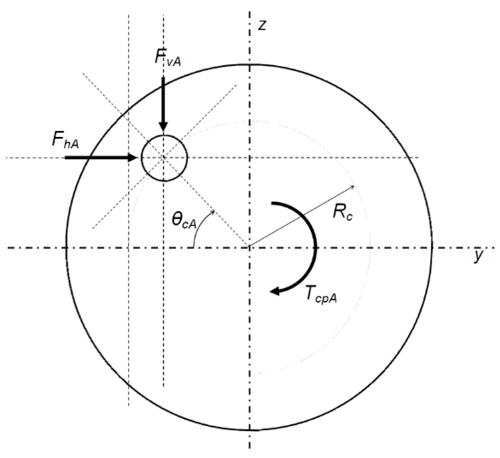
The two cams support and guide the rail carrier such that the rails are moved through a semi-circle. Therefore a 2D reaction force is generated (due to inertia and the elastic bending of the rails which is feedback as a load onto the cams/gear-head/drive motor through the rail carrier and rail assembly. The force vectors that act on a single cam (e.g., cam-A) are shown in Figure 5 and the governing equations are expressed in Equation (5) where the torque on the cam is calculated in Equation (6).
The effect of the dead-zone or backlash at either end of the cam rotation is significant is included in the model (via Equation (5)). The mass of the rail carrier is shared equally between the two cams, cam-A and cam-B, so is included in the cam inertial term, . The vertical () and horizontal forces in Equation (5) are passed to the Simulink model from the SimPack model.
3.2. The Switch Rail Model in Simpack
The rail elements of the system are modelled using FEA first to check the bending of the switch rails during switching action (shown in Figure 6a). The material properties of the rail are assumed to be isotropic steel with Young’s modulus and Poisson’s ratio of 200 GPa and 0.3, respectively. A second-order quadratic tetrahedral element, C3D10 [24] is used to create the finite element mesh of the rail bodies. The switch rail boundary conditions are that the rails are fixed in all dimensions at the heel position. The rail is free to bend and twist throughout the remaining length as a result of the forces applied at the bearer positions.
The Finite Element (FE) model is used first to determine the actuator bearer positions in the switch layout. It was determined that the first actuator position should be the first bearer (B1) to ensure the closed position at the front-toe of the switch (see Figure 6b). The switch rails have to be lifted minimum to the cam radius at those bearer locations to allow free movement. The cam radii of the three actuator bearers are determined using the required switch rail movement, which is a function of the switch geometry of the switch. These cam radii are 65 mm (Bearer 1), 50.6 mm (Bearer 2) and 38.2 mm (Bearer 3). The actuator locations are selected as 1st, 3rd and 5th bearer positions. The selected configuration ensures that the rail carrier moves in a semi-circular way without interference with any other cams.
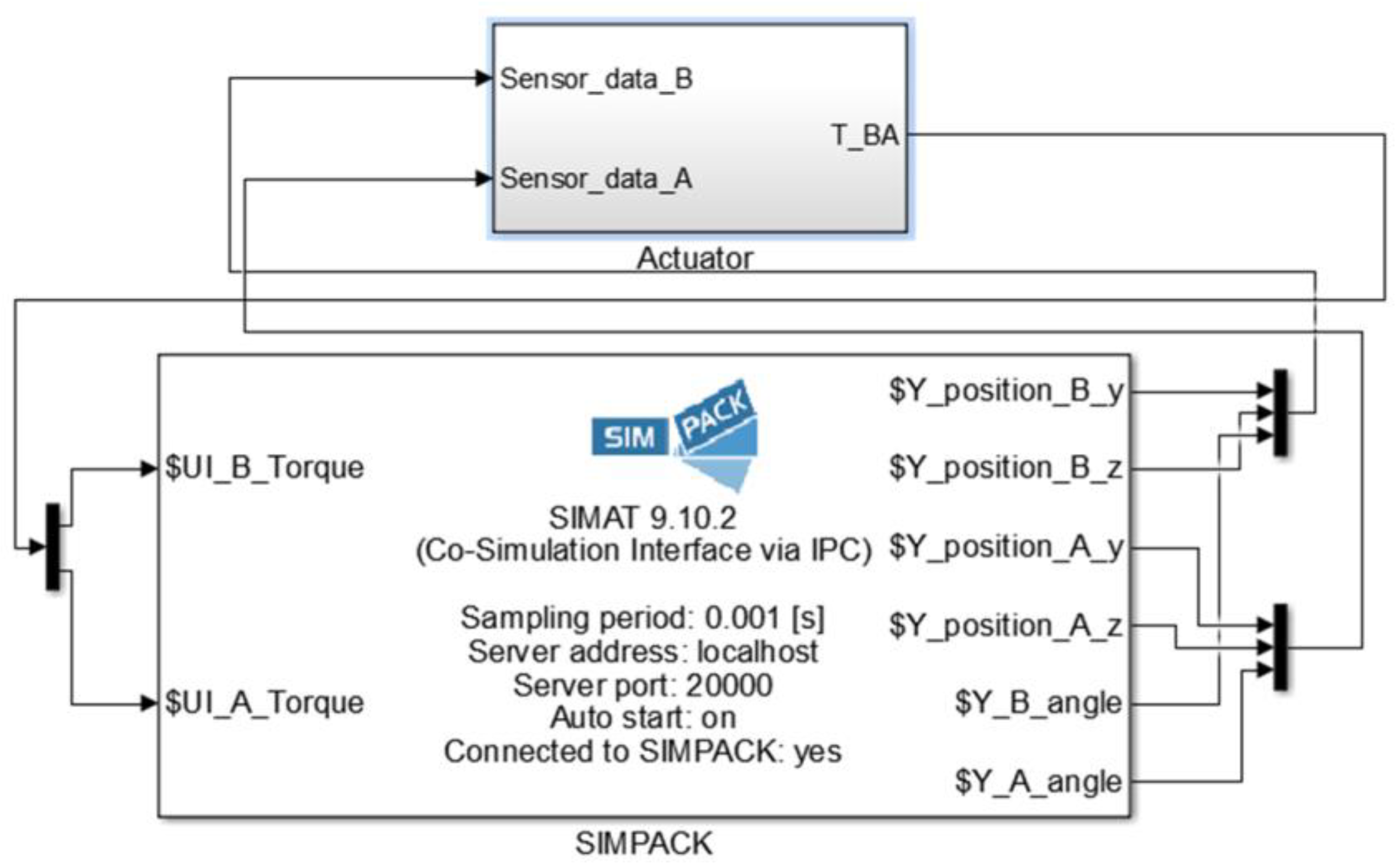
These finite element bodies of the switch and stock rails are then converted into flexible body files (.fbi files) using the model reduction technique in Abaqus. An MBS model of the switch panel is then developed using Simpack. This MBS model is then connected to the actuator model developed in Simulink to form a co-simulation in Simulink as shown in Figure 7. This co-simulation is constructed so that the designed controller, which will be explained in the following section, can be connected to the MBS as shown in Figure 4. The sensor data are fed to the actuator and controller modelled in Simpack and the actuation torque is fed to the MBS model. The data exchange between Simulink and Simpack in the co-simulation environment is carried out at a fixed time step of 0.001 s.
4. Controller Design, Implementation and Model Validation
The most important purpose of the dynamic model is its use for controller design and validation in simulation—prior to testing on the real switch. In this section, the controller design and architecture will be discussed, then the implementation will be summarised, finally, the simulated and experimental step response results will be presented.
4.1. Controllers Design
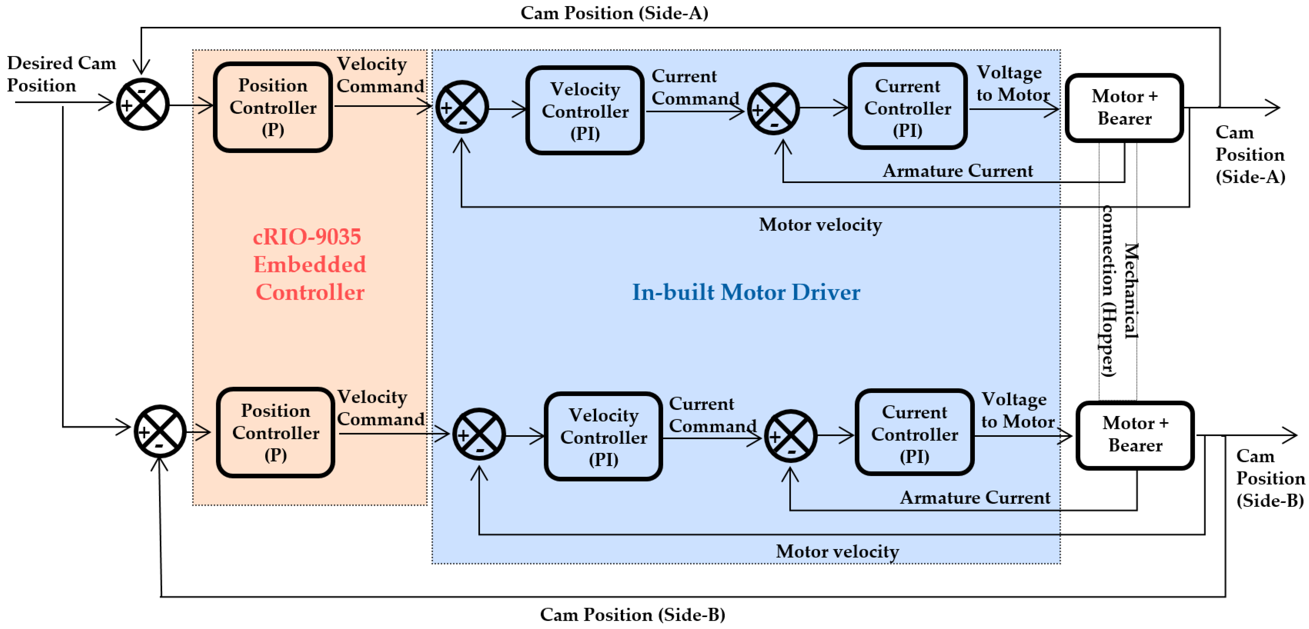
The synchronisation of the motion of the three actuator bearers and their six motors is essential for the correct operation of the switch. Hence, all actuator bearers use the same control algorithm and control gains. Examining the control loops for each bearer, we see that both motors within the single actuator bearer, are controlled by three cascaded loops: inner-loop motor current controller, centre-loop motor velocity controller and outer-loop position controller (see Figure 8). Both the inner current controller and the motor velocity controller are proportional-integral (PI) controllers. The outer loop position controller is a proportional (P) controller which was found to offer zero steady-state error performance due to the natural inclusion of integral action via the velocity loop.
The control performance and stability requirements for the system shown in Table 2. The maximum current is considered in the design process, but in practice is limited automatically by the motor drivers. The phase and gain margin requirements of 6 dB and 60° are essential to ensure robust relative stability of the system in the presence of uncertainties. The settling time requirement is set to be less than 7 s to comply with the UK railway switching time norms. The maximum allowable overshoot is specified is as 2° to ensure that the cams do not over-rotate during transit. This is a very large margin of error which ensures that the cam will not touch other mechanical components by over-rotating. For each active bearer, the two cam control systems are supplied with the desired cam angle as their setpoint (see Figure 8). The feedback signal from the cam encoders is used in controlling the motion of both motors such that the switch rails reach their expected position, Reverse or Normal, as commended by the set-point angle (0° or 180°, respectively).
The Nichols plots generated as part of the controller design process are shown in Figure 9; it is clear that the control stability margin requirements are met. The current controller Nichols plot (see Figure 9a) shows an infinite gain margin and phase margin of 90.2° which are well above the requirement. The middle loop is then analysed in the same manner to generate gains for the velocity controller. The Nichols plot in Figure 9b, shows the gain and phase margins to be 57 dB and 90.6°, respectively. Once again these margins are large compared to the control requirements, but the time responses are sufficiently fast that it is not necessary to use higher gains. The outer position loop controller is designed last and the corresponding Nichols plot is shown in Figure 9c. The gain and phase margins are 61.5 dB and 88.6°, respectively, which again more than satisfy the control requirement shown in Table 2. The high margins ensure the stability of the system even in the potential event of high gain and phase modelling errors/uncertainties; which give confidence that the closed-loop systems on the real switch will be stable and behave according to requirements. The time-response simulation results, which were checked at each design step and are shown for the final design later (in Section 4.3) predict a rise time of around 2.5 s and a settling time of approximately 5 s when operated with a single actuator bearer.
4.2. Control Algorithm Implementation
A number of different railway working conditions are considered during the design process of the full system. Figure 10 shows the internals of the track switch control cabinet (shown as 9 in Figure 2) and both the front panel and the block diagram windows of the controllers’ code developed using the NI-LabVIEW software to drive the six servo motor drives of the track switch. From the front panel window, the operator can check the state of the switch by both the position (angles) of each cam encoder and the indication from the detection system. The operator can change the current track-switch state to either Normal (0°) or Reverse (180°) positions from an exterior electrical toggle-switch.
The central processor (cRIO-9035) from National Instrument is selected as it is suitable for use in an environment with high shock and vibration. Six analogue input/output and digital input/output modules were selected based on the required input and output signals. The cRIO-9035 processor with the input/output modules is installed alongside the six digital motor drives within the location cabinet.
The angle control laws discussed above (in Section 4.1) are implemented as follows. The current loop and motor velocity loop implementation are facilitated by the motor driver units. Hence the PI gains identified using the simulation design model can simply be downloaded onto the motor driver-hardware. The outer loop position control is programmed in the NI-LabVIEW code and implemented on the cRIO-9035 embedded controller. Along with the controller, other safety functions are, of course, included for a safe overall operation of the switch during the experiments. For example, an emergency stop switch and indicators for the operator such as allowing them to see if any of the bearer covers (Figure 2) are open (or closed).
4.3. Validation of the Co-Simulation Model
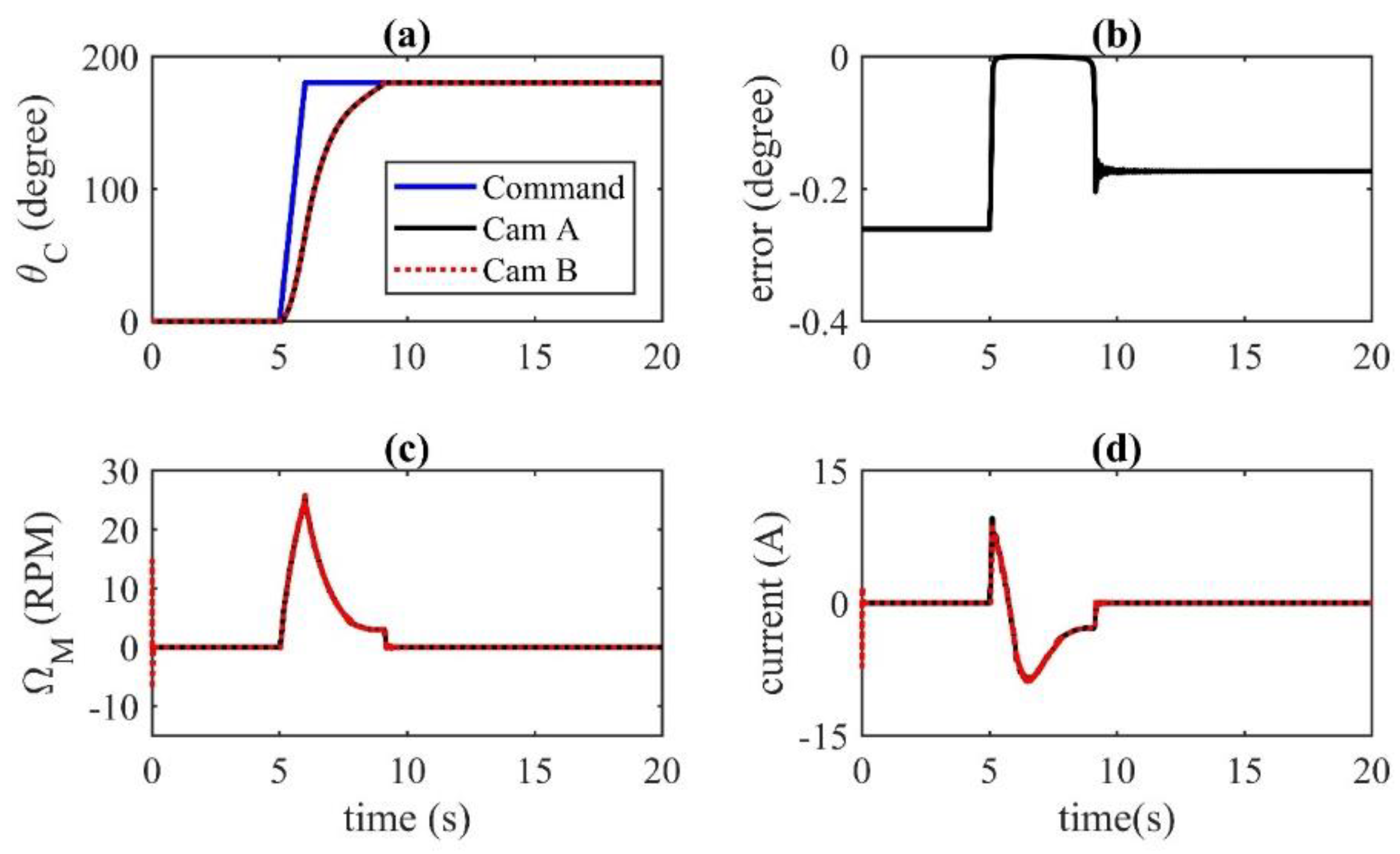
In this section, the results of step-response in the co-simulation for the full switch model are presented, with a single actuator bearer in operation. The results from the dynamic model with controllers are plotted in Figure 11, they show that the differences between the two cam angles (cams A and B) are seen to be negligible (shown in Figure 11b), which ensures no tilting of the rail carrier. Figure 11c shows that the differences in the motor velocities in both the motors are negligible in the co-simulation which ensures synchronised motion of the two motors and the cams. The plots of the motor velocities of the two motors within an actuator show agreement as would be expected. The nature of the current plots for both the assemblies also matches. The maximum current also satisfies the current limitation of the system. Overall this suggests that the controllers designed will appropriately govern the position of the switch rails.
The experimental results from the implemented system are presented along-side the simulation results and used to validate the co-simulation model. The validation results with one active bearer (the third bearer (B3) in Figure 2) are presented in Figure 12. The results with a step-change in command from 0° to 180° shows that the cam rotates as desired. The 0° corresponding to the cam position that places the switch rails in the Normal position, whereas the 180° is reached by the cam when the switch rails are placed in the Reverse position. In the cam angle plot in Figure 12, the result from the co-simulation is shown with cam sensor data from the experiment and it shows a good agreement apart from the small difference in the start-up phase of the plot. The cam angle sensor data from the experiment shows that the cam settles at an angle of 180°, which is perfect because the hoppers carrying the switch rails rest on the locking block before the full 180° rotation. The other two data which are available from the experiment are the motor angular velocity and motor input current which are also shown to agree with those from the co-simulation result in Figure 12. It is seen from Figure 12 that the control requirements are satisfied such as settling time (4.8 s), maximum motor current (<10.4 A) and maximum overshoot (0°).
5. Experimental Results and Redundancy Actuation of the Track Switch
This section presents the performance of the system in terms of the experimental data for the three active bearers of the track switch. The implemented control scenario is first examined running the track switch with all three actuators B1, B2 and B3—the fault-free scenario (in Section 5.1). Then tests progress to running the switch with any two bearers (B1 & B2, B1 & B3 or B2 & B3) and finally, with only one actuator B1, B2 or B3. Note graphs are not plotted for all of these scenarios, but representative results are shown for each and the full set of results are presented in the form of a table.
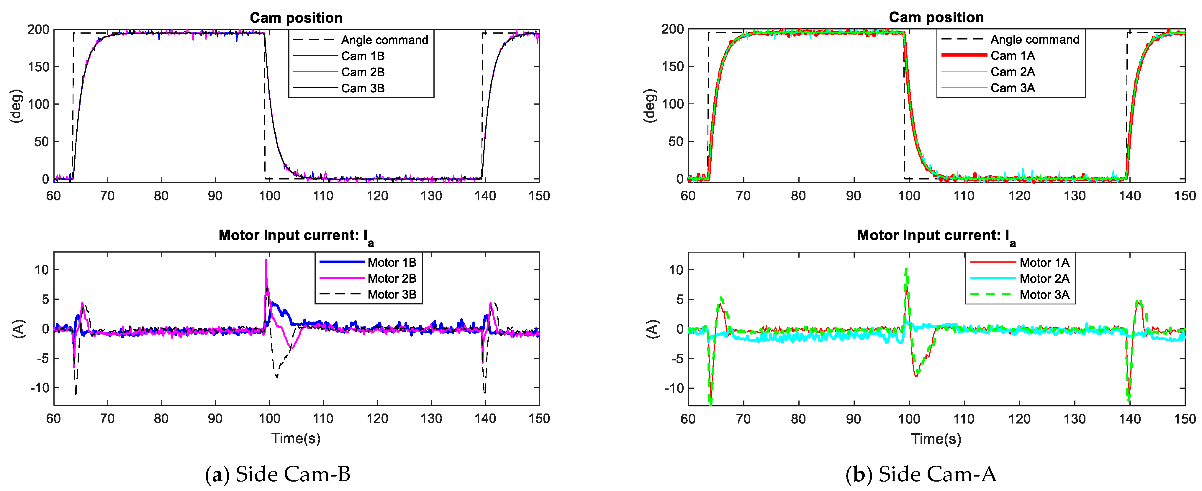
In this research, the synchronised motion of all six motors (will be shown as Cams 1A, 1B, 2A, 2B, 3A, 3B) within the three actuator bearers is ensured by the controllers described in the previous section. The switch actuators are required to move in a semi-circular path and rotate from 0° to 180° (and back). The performance requirements were given previously in Table 2. To ensure locking at each of the two positions a steady-state error response for the step cam position must equal zero. Thus, the result discussion will focus on these two parameters.
5.1. Testing Normal Actuation with Three Actuators
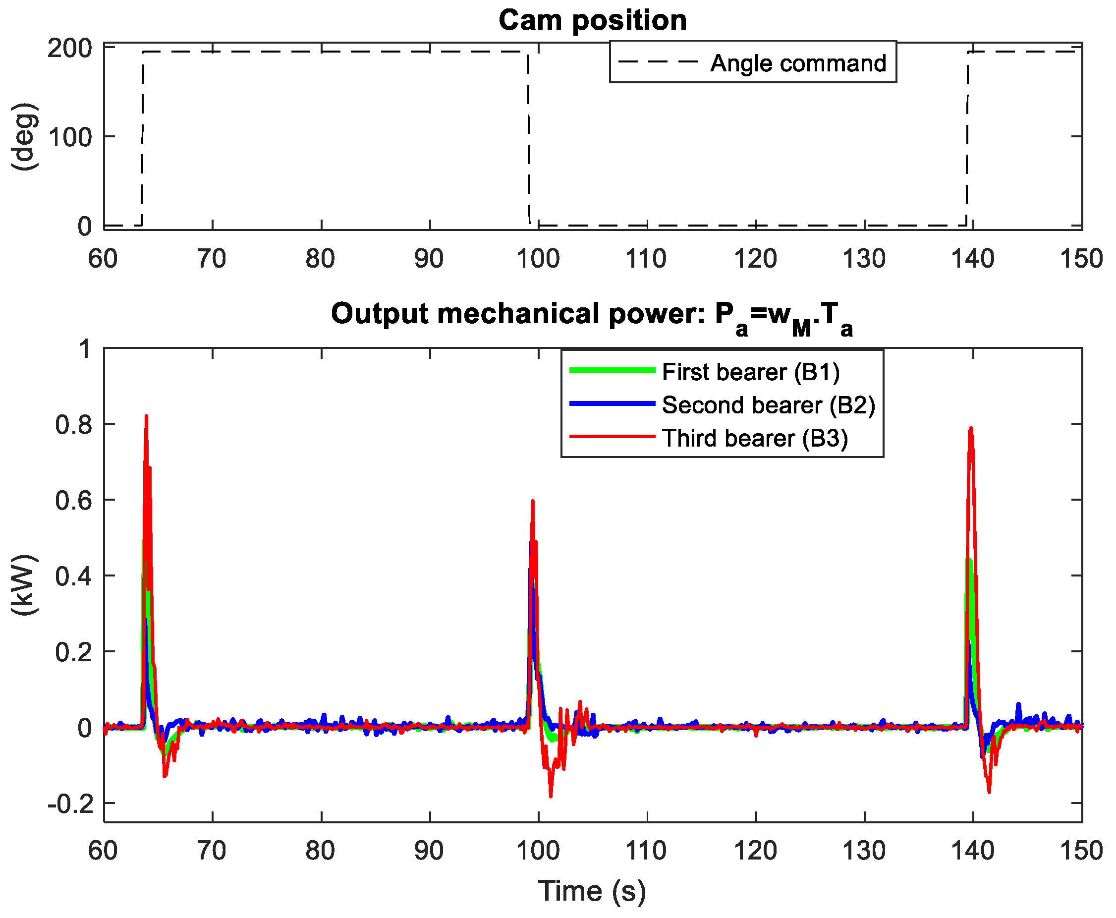
In normal operating conditions, all the three-actuator bearers will work to perform the switching task. Figure 13 shows the performance of the system operating with all the actuator bearers. The cam angle plots ensure that the cams are rotating synchronously. The cam position signal, which is the reference input signal to the control system (see Figure 8), changes from 0° to 180° (a move from Normal position to Reverse position). It is clear that the resulting closed-loop system, shown in Figure 13, meets the step response requirements (Table 2); with a settling time of 5.1 s, zero overshoot and no steady-state error. The maximum input current for each motor does not exceed 14A, which also meets the required value stated in Table 2. Thus, the system achieves the required rail switching. Since the current controller is a PI, during the transient response the current of each motor changes its direction (see current curves in Figure 13) before the switch reaches its steady-state which is the new position of the track switch. It can be seen from these current curves that the performance across each pair of motors is not similar. For example, the third bearer (B3) experiences high torque (load) in side-A and the second bearer (B2) in side-B. This is almost certainly caused minor mechanical alignment issues that manifest as uncertainty in the loading on the motors. To calculate mechanical power for each motor in the switch the equation is used. The torque constant of the servo motor (BMH1002T02A1A from Schneider Electric), is 0.72 Nm/A (Table 1). The mechanical power plots from experiments are presented in Figure 14 and show that there is no significant difference between the total mechanical power for the first bearer (B1) and the second (B2), which indicates that B1 and B2 take a similar load in this case. However, the power curves show that the third bearer (B3) does most of the useful work (with a peak mechanical power of 0.85 kW provided jointly by the two motors of B3). Dealing with this was beyond the scope of this current study (which permitted only limited time for on-track testing); however, this might require a further mechanical adjustment of the three bearers to improve the load balanced between all three bearers.
5.2. Testing Redundant Actuation with Two out of Three Actuators
In this test scenario, two of the actuators are active, while the third is disconnected to represent a fault. Clearly, there are three possible combinations to compare. Here we present results for one of those combinations (Figure 15), which is representative of the over two cases, while also summarising all outcomes later in Table 3.
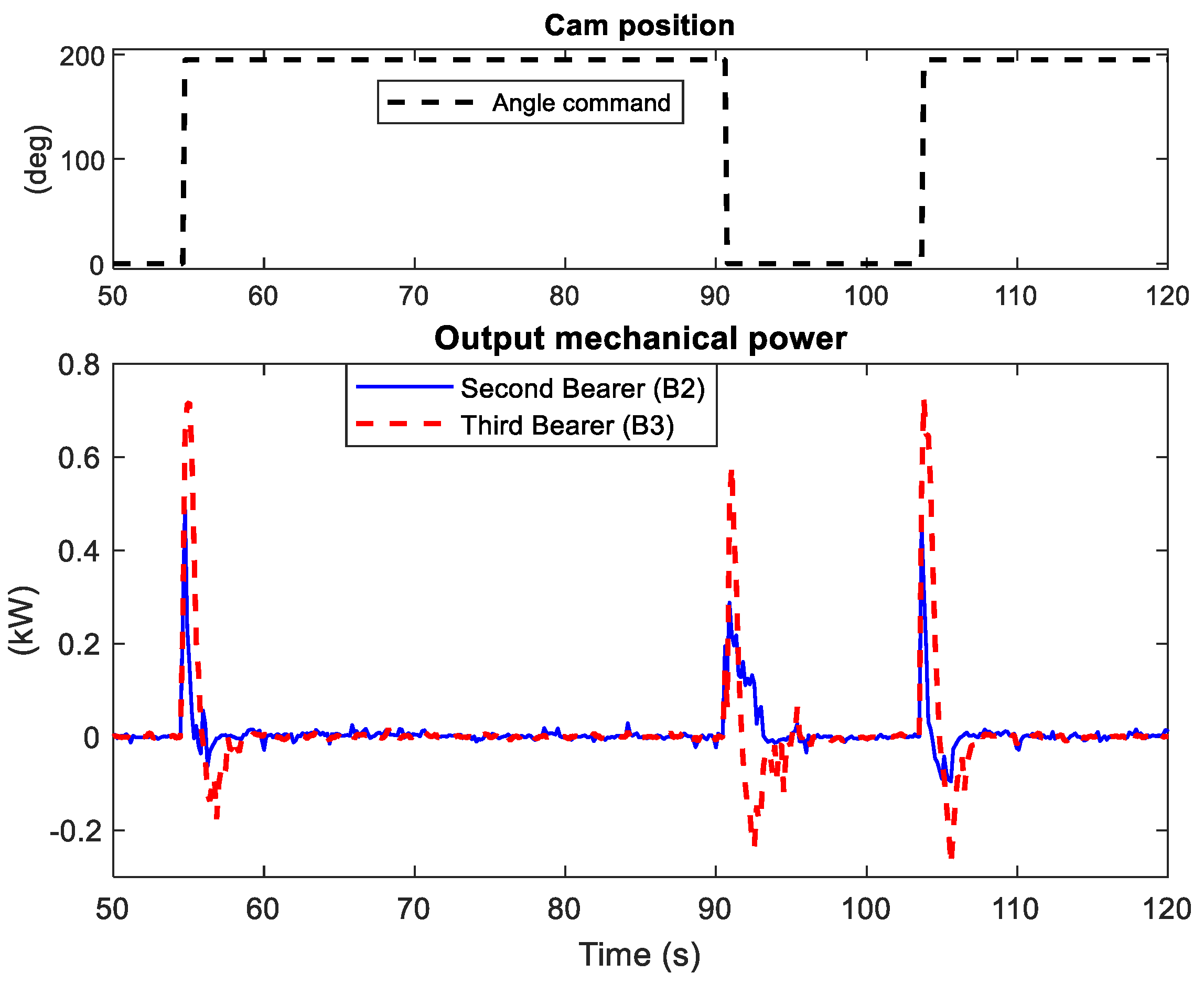
The experiment is carried out with bearer B1 disconnected to represent a complete failure on that unit. Hence, the entire switch operation should be carried out by the second and third bearers (B2 and B3). From Figure 15, we see that the close synchronisation of the four motor positions is achieved and the control requirements are met when the system as the switch is driven back and forth between the two positions, Normal or Reverse (Figure 15). The mechanical power of the two bearers B2 and B3 is plotted in Figure 16, which shows that B3 does a greater share of the work compared to B2, which is similar to the result obtained from the normal/healthy case when running the switch with all three bearers.
It is clear from these results (and those for the other two test cases) that the switch system operating with only two bearers remains capable of achieving its goal. That is, the system still meets the step response performance requirements in the event of a failure in one out of three actuation sub-systems.
5.3. Testing Redundant Actuation with One out of Three Actuators
Here, the switching is achieved by running an individual bearer, B3 then B2 and finally B1. Thus, in this operation scenario, it is considered that the other two bearers are not working. The results showing cam position, current and power are shown in Figure 17a for B3; whilst summary results for B2 and B1 are provided in Figure 17b,c, respectively. In each case, it is seen that synchronous motion of two motors in each bearer, side-A and side-B, is achieved and the step response requirements (see Table 2) are still met. In Figure 17a, it is seen that the motor currents are not identical. This must be caused by uncertainty from mechanical asymmetry causing different loading on the motors. Even in this extreme case (of only one operational actuator), the maximum input current drawn from all motors is less than 20A, which is also within the requirements without needing recourse to the driver current limit.
Figure 17b,c shows the other two tests, which are achieved to confirm the reliability and the viability of the switch for operation by a single actuator. In these two tests, the track switch is operated by the second and first bearers individually. Similar to running the switch by only B3, good performance of the switching system is achieved and the requirements of the step response are perfectly met as expected. The experimental results in single bearer operation mode, show that rail switching is achieved by only a single mechatronic bearer. This achievement is similar when the switch is in the healthy case with all the three bearers working. This important result verifies the capability of the switch system to provide compromised operation after any two actuators’ faults.
5.4. Summary and Comments
The results for all combinations of bearer failure are shown in Table 3. Note, the timing of switching (of setpoint) between the Normal and Reverse position is not identical in each case due to being manually commanded, however, this was observed to have no effect on the step response times. Overall, performance is as desired in all cases: Fully functional (triple bearers), one fault (double bearers) and two faults (single bearer). This is perhaps not surprising as the individual actuators were designed and their motors and drive systems were sized in such a way that they should be able to each perform the switching operation independently (to give 1 out of 3 redundant actuation).
From the table, it is clear that the deterioration of performance is minor even in extreme cases. The fact that switching time remains within the requirements is important and is a testament to the ability of feedback control (not generally used in track-switches) to reduce/remove the effect of external disturbances, uncertainty and faults.
Overall, confirming the ability of the switch to tolerate any two faults is a very important result in terms of the overall system performance and fault tolerance. It verifies that the new switch will remain operational, with a performance that is not noticeably degraded even after a complete failure of two actuators.
6. Conclusions and Future Work
This paper has focussed on the development and test of a new track-switch actuation system, which has been designed to allow fault-tolerant operation of a railway track switch. Development of the dynamic design model which is a co-simulation between Simulink and Simpack has been discussed; links have been made to its use in the design process. In particular, the model’s use for the design of the control system has been covered. Both simulation and experimental results have been compared—showing that the model is indeed representative of the main dynamic response of the actuation and moving rails in the real application. Comprehensive results for the resulting switch and actuation system, installed and tested in a real railway environment, are presented and discussed. The implementation tests showed that the proposed closed-loop control algorithm achieves effective rail switching which met the specified control requirements for the system.
The different tests of the novel switch, in the rail network, has been mainly achieved by three stages. The implemented scenario has been started by operating the track switch using all three actuators, then using two active bearers and finally, with only a single actuator to test robustness to faults. Overall the experimental tests show the rail switching operation is achieved by any two out of the three bearers, and also by every individual bearer. On both through and diverging routes (Normal/Revers switch positions), the experiential results also show that the rebalancing of switch rail loads over each actuator of the track switch is crucial to the success and evolution of this innovation switch.
The research described set out to redesign railway track switches to feature fault tolerance, primarily using redundancy of actuation, to significantly boost reliability and availability, whilst keeping the existing switch layout unchanged. The novel approach that has been presented used three mechatronic actuator-bearers and moved the switch rails through a motion unlike any existing track switch to facilitate passive locking.
Three directions of future research can be proposed: first, develop a top-level controller that should receive a signal from the railway signal interlocking and send a desired cam position command to the individual controller. Second, enable this top-level controller to facilitate load-balancing between the actuator bearers to ensure better sharing of the mechanical load. Finally, consideration of model-based (or other) condition monitoring for the actuator bearers within the track switch system.
Author Contributions
Conceptualization, O.O.; methodology, O.O. and S.D.; validation, O.O. and S.D.; formal analysis, O.O.; writing—original draft preparation, O.O. and S.D.; writing—review & editing, O.O., S.D., T.H. and R.D.; visualization, O.O.; supervision, C.P.W. and R.D.; project administration, C.P.W. and R.D.; funding acquisition, C.P.W. and R.D. All authors have read and agreed to the published version of the manuscript.
Funding
The research described has been supported by Railway Safety and Standards Board (RSSB), UK {the in grant number RSSB/2029S(2015)}, for the project titled “REPOINT Phase 3: Repoint Light Prototype Design and Build”.
Informed Consent Statement
Not applicable.
Conflicts of Interest
The authors declare no conflict of interest.
References
- Bemment, S.D.; Ebinger, E.; Goodall, R.M.; Ward, C.P.; Dixon, R. Rethink rail track switches for fault tolerance and enhanced performance. Proc. Inst. Mech. Eng. Part F J. Rail Rapid Transit. 2017, 231, 1048–1065. [Google Scholar] [CrossRef] [Green Version]
- National Transportation Safety Board. Amtrak Passenger Train Head-on Collision With Stationary CSX Freight Train. 2018. Available online: https://www.ntsb.gov/investigations/AccidentReports/Reports/RAR1902.pdf (accessed on 25 December 2020).
- COMSA Rail Transport Company. S-CODE D1.1 Report: Review of Definitions, Standard Operating Parameters, Best Practice and Requirements, Including Future Technologies and Horizon Scanning. 2016. Available online: http://www.s-code.info/media/1069/s-code-d11-v6-final.pdf (accessed on 11 January 2021).
- Silmon, J.A.; Roberts, C. Improving railway switch system reliability with innovative condition monitoring algorithms. Proc. Inst. Mech. Eng. Part F J. Rail Rapid Transit. 2010, 224, 293–302. [Google Scholar] [CrossRef]
- Kaewunruen, S. Monitoring structural deterioration of railway turnout systems via dynamic wheel/rail interaction. Case Stud. Nondestruct. Test. Eval. 2014, 1, 19–24. [Google Scholar] [CrossRef] [Green Version]
- Hamadache, M.; Dutta, S.; Olaby, O.; Ambur, R.; Stewart, E.; Dixon, R. On the fault detection and diagnosis of railway switch and crossing systems: An overview. Appl. Sci. 2019, 9, 5129. [Google Scholar] [CrossRef] [Green Version]
- Bemment, S.; Dixon, R.; Goodall, R. Redundantly engineered points (REPOINT) for enhanced reliability and capacity of railway track switching. In Proceedings of the 10th World Congress on Railway Research (WCRR), Sydney, Australia, 24–27 November 2013; Available online: https://www.sciencedirect.com/science/article/pii/S2405896316321541 (accessed on 11 January 2021).
- S-CODE. Home|S-Code. 2017. Available online: http://www.s-code.info/ (accessed on 25 December 2020).
- Hamadache, M.; Ambur, R.; Dutta, S.; Shih, J.Y.; Stewart, E.; Olaby, O.; Dixon, R. Innovative Technologies for Railway Track Switches. In 21st IFAC World Congress; IFAC: Berlin, Germany, 2020; Available online: https://research.birmingham.ac.uk/portal/en/publications/innovative-technologies-for-railway-track-switches(e1020111-308d-4939-88e7-043d9b84b4d8).html (accessed on 11 January 2021).
- Olaby, O.; Hamadache, M.; Ambur, R.; Dutta, S.; Stewart, E.; Dixon, R. Novel Actuation Mechanism for Railway Track Switch System Based on Maglev Technology. In 21st IFAC World Congress; IFAC: Berlin, Germany, 2020; Available online: https://research.birmingham.ac.uk/portal/en/publications/novel-actuation-mechanism-for-railway-track-switch-system-based-on-maglev-technology(03034028-c768-4bf0-bf29-7f9ce0a46cd7).html (accessed on 11 January 2021).
- In2Rail. Available online: http://www.in2rail.eu/ (accessed on 25 December 2020).
- de Roos, R. Innovative Switch & Crossing Design. Available online: http://www.winterproofturnout.info/img/works/ISBN9789090330037.pdf (accessed on 11 January 2021).
- Sarmiento-Carnevali, M.L.; Harrison, T.J.; Dutta, S.; Bemment, S.D.; Ward, C.P.; Dixon, R. Design, construction, deployment and testing of a full-scale repoint light track switch (I). In Institution of Mechanical Engineers—Stephenson Conference: Research for Railways 2017; Institution of Mechanical Engineers: London, UK, 2017; pp. 409–416. [Google Scholar]
- Dutta, S.; Harrison, T.J.; Sarmiento-Carnevali, M.L.; Olaby, O.; Bemment, S.D.; Ward, C.P.; Chalisey, A.; Dixon, R. REPOINT—Designing a radically new switch machine. In Railways 2018—The Fourth International Conference on Railway Technology, Sitges-Spain; Elsevier: Amsterdam, The Netherlands, 2018; pp. 3–5. Available online: https://dspace.lboro.ac.uk/dspace-jspui/handle/2134/35150 (accessed on 11 January 2021).
- Olaby, O.; Dutta, S.; Harrison, T.; Ward, C.P.; Dixon, R. REPOINT-light full-scale track switch REPOINT-Light Full-scale Track Switch: Experimental Results at a Railway Testing Site. In Proceedings of the 8th IFAC Symposium on Mechatronic Systems 2019, Vienna, Austria, 4–6 September 2019; Available online: https://research.birmingham.ac.uk/portal/files/86155384/00_REPOINT_Mechatronics_2019.pdf (accessed on 11 January 2021).
- Bemment, S.D.; Goodall, R.M.; Dixon, R.; Ward, C.P. Improving the reliability and availability of railway track switching by analysing historical failure data and introducing functionally redundant subsystems. Proc. Inst. Mech. Eng. Part F J. Rail Rapid Transit. 2018, 232, 1407–1424. [Google Scholar] [CrossRef] [PubMed] [Green Version]
- Bemment, S.; Dixon, R.; Goodall, R.; Brown, S. Redundantly engineered track switching for enhanced railway nodal capacity. In Proceedings of the 1st IFAC Workshop on Advances in Control and Automation Theory for Transportation Applications, Istanbul, Turkey, 16–17 September 2013; Volume 46, pp. 25–30. [Google Scholar] [CrossRef]
- Bemment, S.D.; Dixon, R.; Goodall, R.; Ward, C.P.; Wright, N. Design, construction and operation of a REPOINT laboratory demonstrator. In Stephenson Conference Research for Railways 2015; Institution of Mechanical Engineers: London, UK, 2015; pp. 221–231. [Google Scholar]
- Wright, N.; Bemment, S.; Ward, C.; Dixon, R. A model of a repoint track switch for control. In Proceedings of the 2014 UKACC International Conference on Control (CONTROL), Loughborough, UK, 9–11 July 2014; pp. 549–554. [Google Scholar] [CrossRef] [Green Version]
- Bezin, Y.; Sarmiento-Carnevali, M.L.; Sichani, M.S.; Neves, S.; Kostovasilis, D.; Bemment, S.D.; Harrison, T.J.; Ward, C.P.; Dixon, R. Dynamic analysis and performance of a repoint track switch. Veh. Syst. Dyn. 2020, 58, 843–863. [Google Scholar] [CrossRef]
- Kaijuka, P.L.; Dixon, R.; Ward, C.P.; Dutta, S.; Bemment, S. Model-Based Controller Design for a Lift-and-Drop Railway Track Switch Actuator. IEEE/ASME Trans. Mechatron. 2019, 24, 2008–2018. [Google Scholar] [CrossRef] [Green Version]
- Dutta, S.; Harrison, T.; Ward, C.P.; Dixon, R.; Scott, T. A new approach to railway track switch actuation: Dynamic simulation and control of a self-adjusting switch. Proc. Inst. Mech. Eng. Part F J. Rail Rapid Transit. 2020, 234, 779–790. [Google Scholar] [CrossRef]
- Dutra, S.; Olaby, O.; Harrison, T.; Kaijuka, P.; Sarniento-Carnevali, M.; Bemment, S.D.; Ward, C.P.; Dixon, R. Development of Controller for REPOINT Light Railway Track Switch. In Proceedings of the 2018 UKACC 12th International Conference on Control (CONTROL), Sheffield, UK, 5–7 September 2018; p. 126. [Google Scholar] [CrossRef]
- Systèmes, D. ABAQUS 6.14 Analysis User’s Guide; The 3DEXPERIENCE Company: Waltham, MA, USA, 2014; Volume IV, Available online: http://130.149.89.49:2080/v6.14/pdf_books/ANALYSIS_4.pdf (accessed on 11 January 2021).
Figure 1.
Different layout for full REPOINT and REPOINT-Light systems (a,b). Numbered elements: 1. Stock rails, 2. Movable switch rails, 3. Common crossing, 4. Check rails, 5. Divergent route, 6. Straight route, 7. Actuators with in-built lock and detection system, 8. POE (Point Operating Unit).
Figure 1.
Different layout for full REPOINT and REPOINT-Light systems (a,b). Numbered elements: 1. Stock rails, 2. Movable switch rails, 3. Common crossing, 4. Check rails, 5. Divergent route, 6. Straight route, 7. Actuators with in-built lock and detection system, 8. POE (Point Operating Unit).

Figure 2.
REPOINT-Light track switch at great central railway Quorn and Woodhouse station, UK: 1. Stock rails, 2. Movable switch rails, 3. Common crossing, 4. Check rails, 5. Actuator bearer with locking elements, 6. Rail detection sensors, 7. Bearer coves, 8. Connections between the control unit and bearer elements, 9. Control unit.

Figure 3.
3D model of a single actuator bearer: 1. Electrical motor and gearbox, 2. Cam and angle encoder, 3. Locking block, 4. Rail carrier for supporting the switch rail (a–c).
Figure 3.
3D model of a single actuator bearer: 1. Electrical motor and gearbox, 2. Cam and angle encoder, 3. Locking block, 4. Rail carrier for supporting the switch rail (a–c).

Figure 4.
Modelling approach.

Figure 5.
Forces acting on a single cam-A.

Figure 6.
(a) Finite Element (FE) model of switch rails, (b) Multibody Simulation (MBS) model of the switch panel in Simpack.
Figure 6.
(a) Finite Element (FE) model of switch rails, (b) Multibody Simulation (MBS) model of the switch panel in Simpack.

Figure 7.
Co-simulation of the switch system.

Figure 8.
Designed single bearer level controller for the track switch.

Figure 9.
Nichols plot for the designed controllers (a–c).


Figure 10.
Location cabinet with hardware installed, for testing at Great Central Railway Quorn and Woodhouse Station, UK.
Figure 10.
Location cabinet with hardware installed, for testing at Great Central Railway Quorn and Woodhouse Station, UK.

Figure 11.
Comparison of performances for both the cams within the actuator: (a) angular position of the cams; (b) error in the angular position between the cams; (c) motor angular velocities; (d) motor input currents.
Figure 11.
Comparison of performances for both the cams within the actuator: (a) angular position of the cams; (b) error in the angular position between the cams; (c) motor angular velocities; (d) motor input currents.

Figure 12.
Validation of the co-simulation model with the experimental results of the track switch system, working by single actuator bearer (third bearer B3, motor side-B).
Figure 12.
Validation of the co-simulation model with the experimental results of the track switch system, working by single actuator bearer (third bearer B3, motor side-B).

Figure 13.
Experimental result, at railway environment, showing the angular position and the current of three mechatronic bearers of the novel track switch. The system operating with all three bearers; B1, B2 and B3.
Figure 13.
Experimental result, at railway environment, showing the angular position and the current of three mechatronic bearers of the novel track switch. The system operating with all three bearers; B1, B2 and B3.

Figure 14.
Mechanical power of the three bearers when the system operating with all three bearers; B1, B2 and B3.
Figure 14.
Mechanical power of the three bearers when the system operating with all three bearers; B1, B2 and B3.

Figure 15.
Performance of the system operating with two bearers; the second bearer (B2) and the third bearer (B3) at double actuation mode.
Figure 15.
Performance of the system operating with two bearers; the second bearer (B2) and the third bearer (B3) at double actuation mode.

Figure 16.
Mechanical power of the two bearers B2 and B3 at double actuation mode.

Figure 17.
Performance of the track switch system running with single bearer at single actuation mode (a–c).
Figure 17.
Performance of the track switch system running with single bearer at single actuation mode (a–c).


Table 1.
Mathematical symbols used in the switch model and their values.
| Description | Value | Units | |
|---|---|---|---|
| Bc | Cam frictional damping coefficient | 0.004 | Nm/(rad/s) |
| Bg | Gearhead frictional damping coefficient | 1.91 × 10⁻⁵ | Nm/(rad/s) |
| BM | Motor frictional damping coefficient | 4.01 × 10⁻⁴ | Nm/(rad/s) |
| FvA | Vertical force acting on the cam connected to switch rail A | N | |
| FhA | Horizontal force acting on the cam connected to switch rail A | N | |
| ia | Motor current | A | |
| Jc | Cam inertia | 0.003 | kgm2 |
| Jg | Gearhead inertia | 2.16 | kgm2 |
| JM | Motor inertia | 6.28 | kgm2 |
| Kgh | Rotational stiffness of the gearhead | 41250 | Nm/rad |
| Kv | Back emf constant of the motor | 0.441 | V/(rad/s) |
| KT | Torque constant of the motor | 0.72 | Nm/A |
| La | Armature inductance | 2.7 | mH |
| mh | Mass of the rail carrier | 25 | kg |
| ng | Gear ratio | 20 | |
| mrail | Mass of the rail on the rail carrier | kg | |
| PM | Output mechanical power | kW | |
| Ra | Armature resistance | 0.54 | Ω |
| Rc | Radius of the cam | 0.065 | m |
| TcpA | Torque on the cam connected to straight Rail A | Nm | |
| Tgo | Gearhead output torque | Nm | |
| TM | Motor electrical torque | Nm | |
| Vm | Motor voltage | V | |
| θgo | Angular position of gearhead output shaft | rad | |
| θcA | Angular position of the cam connected to switch rail A | rad | |
| θM | Motor angular position | rad | |
| ωgi | Gearhead input angular velocity | rad/s | |
| ωgo | Gearhead output angular velocity | rad/s | |
| ωM | Motor angular velocity | rad/s |
Table 2.
Control requirements for designing the controller for the switch system.
| Parameter | Required Value |
|---|---|
| Gain Margin | >6 dB |
| Phase Margin | >60° |
| Maximum overshoot | <2° |
| Maximum Current | <20 A |
| Settling Time | <7 s |
| Steady-state error | 0° |
Table 3.
Closed-loop performance under fault-free (triple), one out of three faults (double) and two out of three faults (single) actuation.
Table 3.
Closed-loop performance under fault-free (triple), one out of three faults (double) and two out of three faults (single) actuation.
| Switch Mode Operation | Actuators (Bearers) Names | Settling Time (s) | Steady-State Error (°) | Overshoot (°) | Peak of Input Current (A)— for Each Motor | Peak of Output Mechanical Power (kW)— for Each Actuator | ||
|---|---|---|---|---|---|---|---|---|
| Side-A | Side-B | |||||||
| Triple bearers | B1 & B2 & B3 | B1 | 5.1 | 0 | 0 | 11.8 | 4.5 | 0.49 |
| B2 | 5 | 0 | 1 | 2.31 | 11.72 | 0.48 | ||
| B3 | 5.1 | 0 | 1 | 13.15 | 11.71 | 0.85 | ||
| Double bearers | B1 & B3 | B1 | 5 | 0 | 1 | 10.39 | 7.66 | 0.56 |
| B3 | 5 | 0 | 0 | 13.07 | 11.34 | 0.99 | ||
| B2 & B3 | B2 | 5.1 | 0 | 0 | 6.09 | 7.69 | 0.49 | |
| B3 | 4.9 | 0 | 0 | 13.16 | 8.63 | 0.72 | ||
| B1 & B2 | B1 | 4.9 | 0 | 1.2 | 15.3 | 3.96 | 0.77 | |
| B2 | 5 | 0 | 1.1 | 12.95 | 14.5 | 0.94 | ||
| Single bearer | B1 | 5.1 | 0 | 0 | 11.33 | 14.15 | 0.81 | |
| B2 | 5 | 0 | 0 | 15.27 | 14.05 | 1.11 | ||
| B3 | 5.1 | 0 | 0 | 15.63 | 15.42 | 1.25 | ||
Publisher’s Note: MDPI stays neutral with regard to jurisdictional claims in published maps and institutional affiliations. |
© 2021 by the authors. Licensee MDPI, Basel, Switzerland. This article is an open access article distributed under the terms and conditions of the Creative Commons Attribution (CC BY) license (http://creativecommons.org/licenses/by/4.0/).
Share and Cite
MDPI and ACS Style
Olaby, O.; Dutta, S.; Harrison, T.; Ward, C.P.; Dixon, R. Realisation of a Novel Functionally Redundant Actuation System for a Railway Track-Switch. Appl. Sci. 2021, 11, 702. https://doi.org/10.3390/app11020702
AMA Style
Olaby O, Dutta S, Harrison T, Ward CP, Dixon R. Realisation of a Novel Functionally Redundant Actuation System for a Railway Track-Switch. Applied Sciences. 2021; 11(2):702. https://doi.org/10.3390/app11020702
Chicago/Turabian StyleOlaby, Osama, Saikat Dutta, Tim Harrison, Christopher P. Ward, and Roger Dixon. 2021. "Realisation of a Novel Functionally Redundant Actuation System for a Railway Track-Switch" Applied Sciences 11, no. 2: 702. https://doi.org/10.3390/app11020702
Note that from the first issue of 2016, this journal uses article numbers instead of page numbers. See further details here.