Disassembly Sequence Planning (DSP) Applied to a Gear Box: Comparison between Two Literature Studies


Department of Industrial Engineering, Alma Mater Studiorum University of Bologna, Viale Risorgimento 2, I-40136 Bologna, Italy
*
Author to whom correspondence should be addressed.
Appl. Sci. 2020, 10(13), 4591; https://doi.org/10.3390/app10134591
Submission received: 11 May 2020
/
Revised: 19 June 2020
/
Accepted: 24 June 2020
/
Published: 2 July 2020
Abstract
:This work aims to analyze the characteristics and importance that design techniques for disassembly assume in the modern design phase of a mechanism. To this end, the study begins by considering a three-dimensional model of a gear motor, taken from the components of which the overall drawings are arranged and from the relief of those not available. Once the mechanism has been digitally reconstructed, the activity focuses on the study of the optimal disassembly sequence by comparing different methodologies, according to two evaluation criteria—minimizing the time taken and minimizing the number of tool changes necessary to complete the sequence. The main results of the work are (1) defining a standard methodology to improve disassembly sequence planning, (2) finding the best disassembly sequence for the specific component among the literature and eventually new methods, and (3) offering to the industrial world a way to optimize maintenance operations in mechanical products. Referring to the limitation of the present works, it can be affirmed that the results are limited to the literature explored and to the case study examined.
1. Introduction
Disassembly is a reversal process in which a product is separated into its components and/or subassemblies by nondestructive or semi-destructive operations that only damage the connectors/fasteners. If the product separation process is not reversible, this process is called dismantling [1].
The issue of disassembly in the industrial world assumed importance as early as the 1990s, but it is in recent decades that it has established itself as a fundamental pivot of the design phase. Increasing attention to the use of material resources, energy, and awareness of respect for the environment have made the approach to the design and construction of mechanical components essential with a view to optimizing costs and, therefore, reusing materials.
The principle on which disassembly sequence planning (DPS) is based is to enhance the set of pieces in which it is possible to dismantle a component at the end of its life rather than discarding the product in its entirety [1,2,3,4,5,6,7,8].
The prerogatives of design for assembly (DfA) and DSP are different. DfA is a process by which products are designed with ease of assembly in mind (if a product contains fewer parts, it will take less time to assemble, thereby reducing assembly costs) and aims to reduce assembly time and costs; instead, DSP aims to reduce the complexity of disassembly for target components, providing efficient design solutions able to meet the end-of-life requirements of products. This aspect becomes increasingly important and increasingly essential as the complexity of the building increases.
It is evident that there is no universal algorithm that gives the certainty of implementing the disassembly sequence absolutely, but that this procedure is strongly influenced by the type and complexity of the object in question. Therefore, a design phase of this kind is presented as a study and evaluation of the available possibilities.
Although the present works is certainly limited to a specific case study and to a recent reduced literature, we can demonstrate that the present implementation of disassembly sequence planning can be standardized in a repeatable methodology. Moreover, this methodology is interestingly orientated to find out the best disassembly sequence, for a specific component, among the literature. Finally, we can say that the most important research questions can find answers in the results of the methodology, i.e., offering to the industrial world a way to optimize maintenance operations in mechanical products [2,3,4].
DSP can be considered a special application of design for disassembly (DfD). In general, design for disassembly is part of the great theory of design for X (DfX).
Design for X is one of the tools of concurrent engineering; in particular, DfX is an English expression used in the industrial sector to indicate a design method designed based on the product’s life cycle in order to improve quality and reduce costs and times of realization of a project. With this approach, we try to break down the walls of serial design in order to obtain an integrated approach through, for example:
- Design for economic manufacturability;
- Design for producibility;
- Design for testability;
- Design for reliability;
- Design for installability;
- Design for serviceability;
- Design for recycling;
- Design for environment;
- Design for assembly;
- Design for disassembly;
- Design for manufacturing;
- Design for cost.
Design for excellence (DFX) is a systematic approach useful for industrial engineers that are involved in both design and process; the letter “X” represents targeted objectives or characteristics of the product or process. DFX comes under the topic of design for Six Sigma (DFSS), which consists of a design method for the development of new products that aims to better respect the customer’s requests and expectations. There are different approaches to applying the DFSS method: DMADV—define, measure, analyze, design, and validate; CDDOV—concept, define, design, optimization, and verification phases; IDOV—concept, design, optimize, and verify; IDDOV—identify, define, develop, optimize, and verify; RADIOV—requirements, architecture, design, integration, optimization, and verification. These require a cross-functional team approach with the involvement of stakeholders. In order to stay successful in the current market, companies need to meet customer expectations, and continuous efforts should be there to understand these demands. Several aspects, such as cost, quality, reliability, recyclability, etc., should be considered when designing a product according to these consumer needs [5,6,7,8,9,10].
Since the late 1990s, hundreds of papers have been published pertaining to DFX applications in manufacturing. Most of them are widely distributed over many different disciplines and publications. This makes it very difficult for one to locate all the information necessary for the application of DFX in disassembly. A paper that can help researchers and practitioners applying this emerging technology is highly desirable. The objective of this paper is to present the concepts, applications, and perspectives of DFX in disassembly, thus providing some guidelines and references for future research and implementation [1,9,10].
The main objectives of this work are
- The definition of a new DSP standard methodology;
- The detection of the best disassembly sequence for the specific component among the literature.
1.1. The Gearbox Case Study
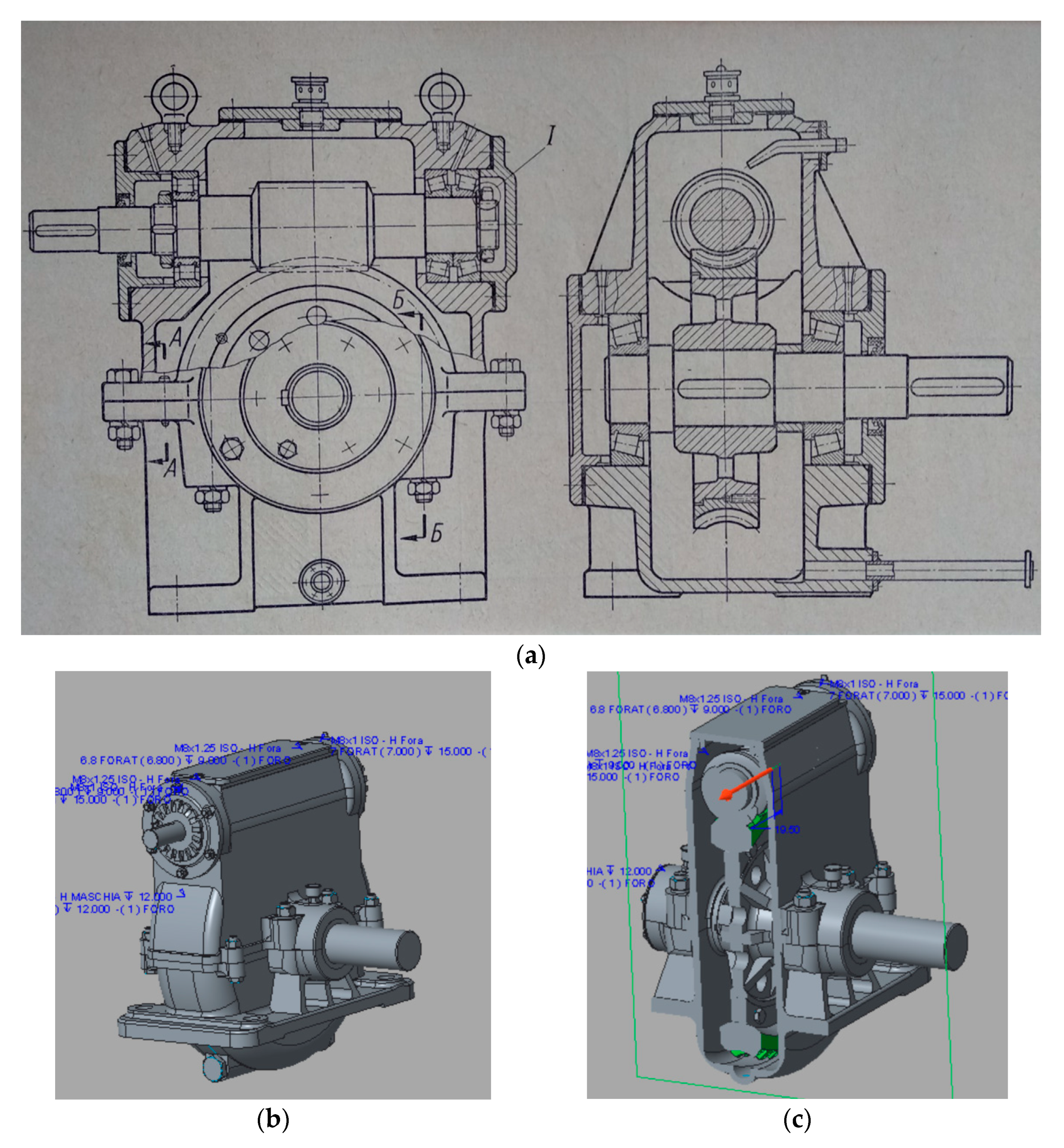
In order to improve what abovementioned process, a reducer of globoid type was considered in this work; in this kind of reducer, a worm screw is coupled with a wheel with straight teeth. This mechanism is generally used in the transmission of motions for generally orthogonal axes, but in any case, they are always skewed, with a low transmission ratio between 1/5 and 1/200. The gearbox taken into consideration, as the case study of the present paper, is depicted, initially, in the 2D drawing (Figure 1a). It is a reducer with a warm screw, usually employed to transmit the motion between two perpendicular asses.
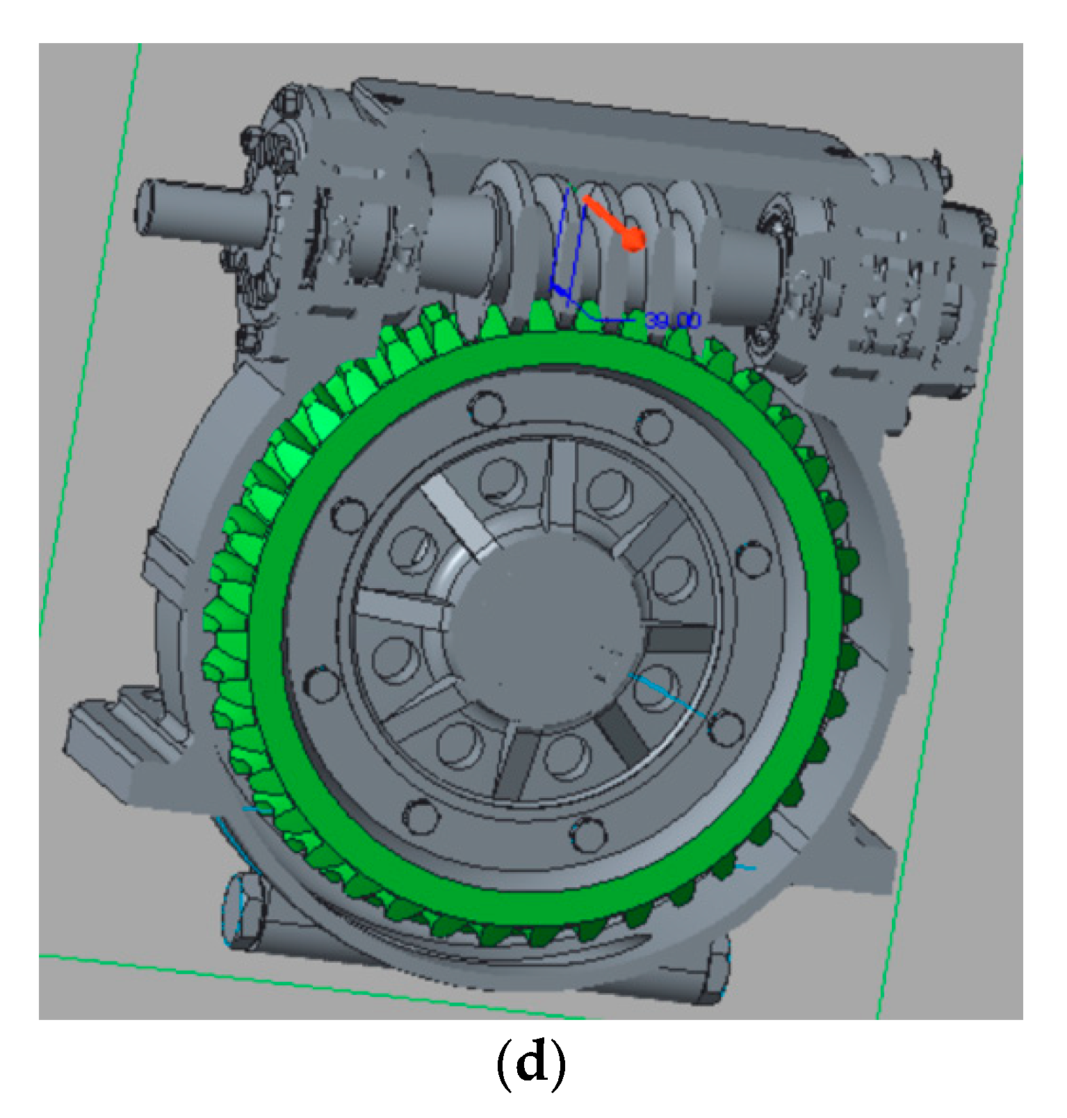
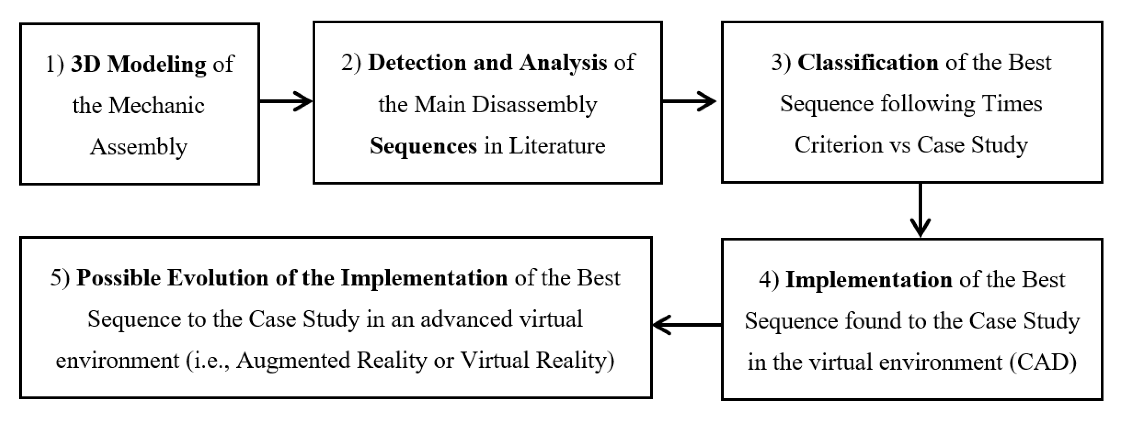
The above 2D drawing is the starting point of the application, because it is the basis from which to generate the 3D model (Figure 1b–d) [11]. Taking reliefs from the technical 2D document, the user is able to realize the 3D CAD (COMPUTER AIDED DESIGN) assembly.
As it can be seen in Figure 1b, the average axial section of the life corresponds to a rack, whose translational motion sets the wheel in rotation. Therefore, indicating with V the speed of translation of the denture and with Ω2 the angular velocity of the wheel, the relative motion between the two components is given by the rolling of a circumference of radius R = V⁄Ω2 on a straight line, elements that can be understood as the primitive lines of the motion itself.
Each revolution of the screw corresponds to an ideal displacement of the denture equal to the pitch of the screw h, which is nothing other than the production of the denture pitch p for the number of threads i: h = p i.
The angular displacement of the wheel due to a turn of the screw (and therefore for a space covered h) is
ϴ2 = h / R = pi / R = 2 πi / z2
Therefore, the transmission ratio of the screw-helical wheel pair can be expressed as
Τ = Ω2 / Ω1
In the present case, the head and foot surfaces of the teeth of both the screw and the toothed wheel are not cylindrical but toric and appear as in Figure 1a for the wheel and Figure 1c for the screw, which in this case it is called globoidal note. These solutions have the purpose of increasing the contact arc between the teeth during the coupling.
By consulting the material available for the construction of the mechanism, the incompatibility between the regulations in force and those used in construction drawings, which have become obsolete, is evident. This requires a thorough analysis of all the sales staff present in the project to replace non-unified pieces with the standards currently in use. Subsequently, the compatibility (or the adjustment, where unavoidable) of the dimensional quotas on the drawings of the parts was verified.
This complication arises again in the designation of the materials used for the manufacture of the components, but this problem has been omitted since the study in question has the objective of verifying the disassembly algorithms proposed in the following chapters without dwelling on the complete product processing cycle. Some metal alloys used, in fact, are not only obsolete in designation but also in use, and this activity does not set itself the intention to verify the adequate use of materials during the design phase of the mechanism.
Regarding the updating of sales staff, it is specified that the UNI regulations were used in order to depart as little as possible from the original version (Table 1).
However, the proposed methodology does not affect the replacement of non-unified pieces with the standards currently in use; in fact, it is independent from the coding of parts, but it is dependent on their geometry and, moreover, on their currently position inside the assembly.
Eventually, the only thing that could be performed before starting disassembly is the reset of the machined operating the phases of the sequence. However, the net time of disassembly does not change.
Besides these aspects, the DSP methodology presented is also not so independent from the materials: the speed of disassembly can change relating to the kindness and properties of each material; in fact, different disassembly speed should be performed in order to follow exigencies of hardness, fragility, deformability, malleability, etc.
1.2. The DSP Methodology
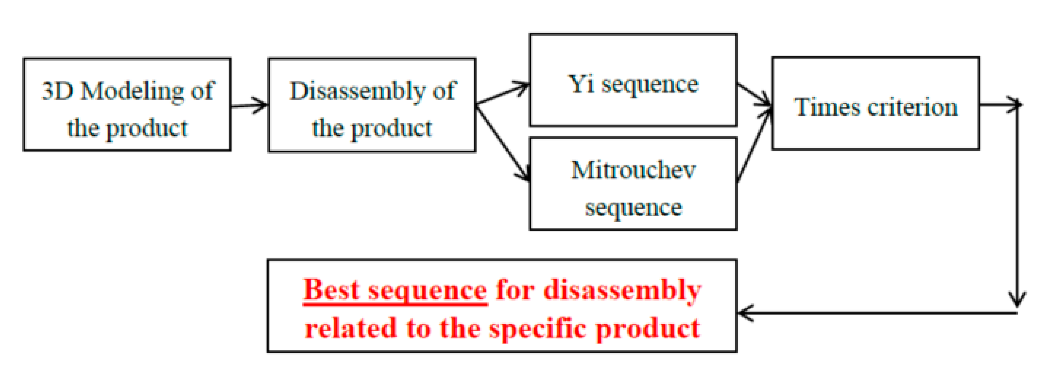
Moreover, a new methodology was developed and used in the present case study; this methodology can be schematized in the following block diagram (Figure 2):
It is therefore described that, in order to find out the best disassembly sequence related to a specific case study (i.e., a mechanic assembly—for example, a globoid type), the following steps must be improved:
- 3D modeling of the mechanic assembly. In order to simulate the best sequence, it is necessary to build the virtual CAD model of the mechanism object of the study; so, subsequently, it will be arranged a model on which “physically” improve the trials of the disassembly sequences;
- Detection and analysis of the main disassembly sequences in literature. In order to find out the best disassembly sequence, it is important to detect in literature the best and recent sequence available. Many are the scientists in the world that publish disassembly sequence; the present study will analyze some and few of them, applying them to the case study.
- Classification of the best sequence following times criterion vs. case study. Using times criterion and applying the disassembly sequences found out in literature, it is possible to make a classification of the best sequences, in order to disassemble and maintain a mechanism or a machine.
- Implementation of the best sequence found to the case study in the virtual environment (CAD). The first implementation of the sequence will take part in the virtual 3D CAD model realized in the step (a). It is possible to see the advancement of the disassembly already in the virtual CAD environment.
- Possible evolution of the implementation of the best sequence to the case study in an advanced virtual environment (i.e., augmented reality or virtual reality). Finally, what happens in CAD virtual environment could be exported also in an advanced virtual environment, just like AR or VR hospitality.
It is also possible to add the following considerations.
The analyzed disassembly sequence, and eventually a third one from them derived, can be applied both to a simple and a complex assembly. However, it was demonstrated by several authors (Francia et al., Frizziero et al., [12,13] etc.) that each sequence could be the best related to a specific assembly. In other words, potentially, any sequence could be the best one; this depends on the special type of assembly.
The best one found in this paper could not be the best one if applied to another products. It does not depend on assembly complexity but only from the specific geometry.
Another aspect to be considered is the correlation between the disassembly sequence and the aging of the components. It is important to say that the first reason because a Disassembly Methodology is studied is exactly the necessity to substitute the specific component that aged or that that no longer works.
So, it is part of the definition of the disassembly methods the possibility of arriving at disassembly and change the desired part. Aging is one of the most important reason why DSP is studied and developed.
2. Selective Disassembly
The fundamental theory behind this approach is what can be defined as “selective disassembly analysis,” a principle according to which the chain of pieces to be disassembled is sought to arrive at a certain element. This is because activities such as the replacement of a component are not necessarily required to dismantle the whole mechanism. Therefore, this technique is useful in many areas besides the one under examination, such as maintenance, recycling or initial assembly.
There are therefore two phases of selective disassembly:
- Understand the possible disassembly sequences to arrive at a specific objective piece;
- Evaluate which of the built sequences is the most advantageous.
All this translates into, given an assembled mechanism and a piece to be disassembled, finding a function that determines the optimal sequence of steps to get there. The optimization can be carried out according to different criteria: shorter disassembly time, lower cost, maximization of recycling or fewer tool changes, and so on.
In this project, two objective criteria have been chosen that are dependent only on the characteristics of the mechanism’s geometries and techniques: the minimization of disassembly and tool change times. It is evident that such a method, although simple and linear at the theoretical level, presents increasing computational difficulties with the complexity of the model in question.
Destructive disassembly (end-of life) is considered to replace the damaged element. In fact, in this case, you should change old elements with new elements but only during the new consequently assembly sequence. So, it is indifferent for DSP and DfD the destructive disassembly sequence study.
Optimal Sequence Search Algorithm
In order to find out the optimal sequence search algorithm, authors will go on applying two scientific sequences, part of literature in this filed, i.e., Yi algorithm and Mitrouchev algorithm (Figure 3). Applying both of them to the assembly previously designed, verifying subsequently through the “times criterion” the best one in term of speed, it is easy to find the most suitable disassembly sequence for the case study, i.e., the gearbox. It is important to underline that in absolute there is not a best sequence; the best sequence is always related to the specific product to which it is applied. Here, the flow-diagram summarizing the main steps of the work:
3. Yi Algorithm
3.1. Introduction
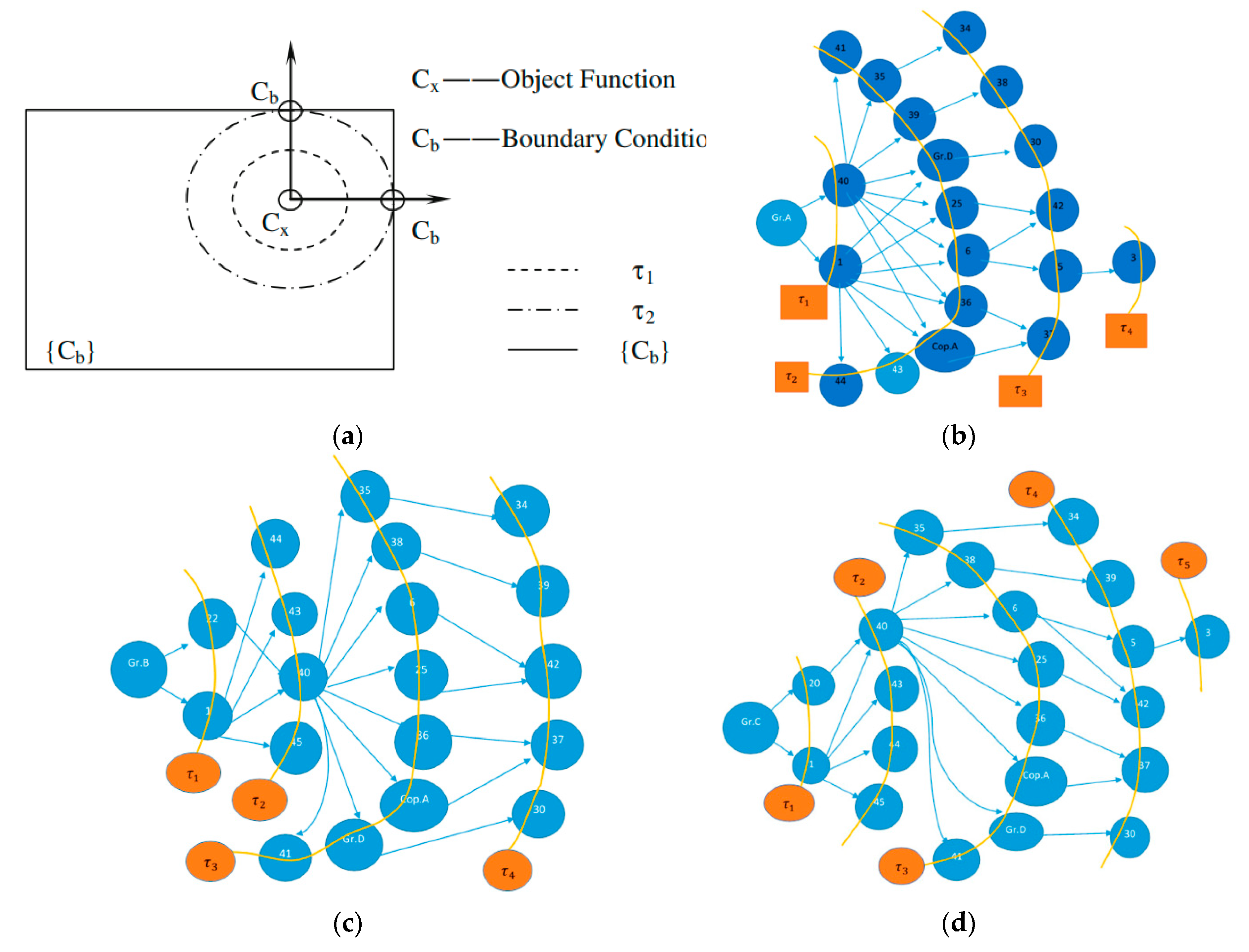
The Yi method [14] from this point of view was created with the aim of simplifying the search for the optimal disassembly sequence. Once an element has been chosen as a “target,” it is ideally imagined as the origin of a wave that crosses, neatly over time, all the other elements to which it is connected. The goal is to create a sort of “map” that highlights, moment by moment, all the different connection levels of the pieces to be traversed by the selected target at the ends of the mechanism, such as the effect of the propagation of a wave from the inside on the outside (Figure 4a–d).
The fundamental hypothesis on which this method is based is, first of all, the deep and total knowledge of the mechanism in question. This burden is then repaid by the extreme simplification in the creation of the “removal influence graph” (hereinafter RG), or the representation of “disassembly wave”.
To do this we must distinguish the components based on the number of adjacent elements that must be removed for local disassembly around the piece. In particular, the following are classified:
- “1-dependent” components if it is sufficient to remove only one element to access them;
- “d-dependent” components if “d” elements need to be removed.
3.2. Algorithm for 1-Dependent Components
For example, if we call Cx the target piece, the propagation source of the wave disassembly. Let us name ta the set of pieces that are part of the same wave level at instant a, where a = 0 identifies the instant relative to the origin, i.e., the level containing only Cx. The distance between two levels is defined by τ, while the set of all pieces disassembled from the origin of the wave up to the time τ–1 is indicated with W.
At time τ0, the wave contains only Cx and therefore t0 = {Cx}, W = {}, while it results W = { t0 ∪ t1 ∪ … ta } for τ = a + 1.
At this point we construct the RG graph starting from the Cx piece, arranging for each ti all the elements that are hit by the wave at the same time. When the instant corresponding to t1 has been built, you will have the first set of pieces directly connected with Cx. Therefore, a number m of possible elements of this level is chosen so that a disassembly sequence [14] is built up to touch an edge element Cb.
In this way, we construct an optimal path OS = {Cb →P Cx} to access the initial piece Cx starting from an element at the edge Cb.
Clearly if there are more on-board elements taken into consideration, an evaluation must be made of the optimal sequence, for example as follows:
Ci τ 0-1 →Cj τ 0 or in alternative Ci τ 0–1 → Ck τ0
3.3. Algorithm for D-Dependent Components
Usually within a structure there are 1-dependent [14] components and d-dependent components. It means that the structure could be represented as the following sequence:
- -
- C4 and C5 depends from C1
- -
- C5 and C6 depends from C2
- -
- C6 and C7 depends from C3
Then it can be assumed that:
- -
- C9, C10 depend from C4
- -
- C11, C12, C13 depend from C5
- -
- Etc.
With the same logic of the previous algorithm, we build some “super graphs”, taking into account the fact that to remove a generic d-dependent component Ci∈ tτ–1 it is necessary to first remove all the components hit by the wave Cj∈ tτ in time t.
The principle is well described by Yi et al.: The above described layout proposed can become more complex, as the resulting RG structure, here below reported [14].

Therefore, in this case, the algorithm starts from a Cx objective component and ends when the edge elements Cb are reached.
We hypothesize that the algorithm finds at the time τ–1 of the d-dependent components Ci∈ tτ–1; at this point what happens is as follows:
- If the elements adjacent to the Ci∈ tτ–1 can be treated as an independent local assembly, the algorithm constructs the sequence by treating these elements as 1-dependent;
- Otherwise, the algorithm generates a disassembly wave tτj (with j = 1, …, d) respectively at time τ;
- The algorithm is executed d-times for each tτj wave, up to being able to remove Ci;
- Unraveled this case, the algorithm continues until the conclusion (when Cb is reached).
3.4. Application to the Model
Consider the gear motor under consideration. Since the objective of this analysis is to identify a sequence of a disassembly of the device, choose the heart of the mechanism as the target element, i.e., the globoid screw that transmits the motion.
The algorithm proceeds from the inside to the outside, gradually highlighting the different contact levels between the various components. To facilitate understanding of the path and not unnecessarily burdening the paragraph, the sequence will be considered complete once the elements of the carcass are reached, without further lingering on the external connection elements that, by logical evidence, must necessarily be all those removed without exception no.
Since the goal is complete disassembly, each subgroup that can be considered as a single component for removal, will be followed, in parallel with the others, also for the disassembly of the individual pieces of which it is formed.
Proceed initially considering the elements to which the worm screw (level t0) is directly connected. Thus, the crown wheel and the two ball bearings on the shaft (t1) are immediately identified. In turn, the groups to which they belong are analyzed: level t2 includes the entire gear unit (crown bearing disc, output shaft and connecting parts) and internal assemblies in the bushes (bearings and spacers) [15,16,17,18,19,20,21].
Now consider these subassemblies as distinct unique components. The t3 level is represented by the adjacent elements—the gear unit arrives at the casing formed by the casing, cover, and grease nipples, while the bush groups are in contact with the elements that interact with the lateral edge caps.
At this point, although the objective of the algorithm has been achieved, the subassemblies still assembled must be disassembled step by step, with the same logic used so far. It is immediate to note that these assemblies are made up of few elements, whose succession of disassembly is immediate.
Analyzing the backward path, after removing the elements of external links, the searched sequence is constructed.
The sequence is shown through the calculation tables of the dismantling times shown in the “Appendix A”.
4. Mitrouchev Algorithm
4.1. Introduction
The Mitrouchev method proposed below is built on theoretical principles different from the previous one. If we consider an assembly, depending on how the elements are connected, for each piece there are different constraint directions.
By analyzing a pair of elements at a time, for each we define the constraint directions (hereinafter referred to as CDs, that is “constraints directions”) for example joining the external vertices of the pieces under examination, as described by Mitrouchev et al. [15].
In the proposed method, the CDs are divided into the following two categories:
- Possible directions of disassembly of the piece;
- Directions that determine one or more collisions during actual disassembly.
As regards the first essential point, the basic idea is to think of the single piece as a “Gauss sphere” [15], to identify the possible directions of translation of the component (henceforth set of directions removal (SDR)), taking into account the constraints created by the contact planes with adjacent elements.
As described by Iacob et al. [16], each piece the hypothetical sphere is reduced based on how it is assembled with the others. It is then necessary to identify the possible disassembly directions for each pair of elements in which there are no collisions. This passage is in fact called “detection collision.” To do this, taking a possible direction of disassembly, the volumes of the elements are projected in a plane orthogonal to this line. If the resulting sections do not have intersections this means that there are no collisions.
4.2. Construction of the Sequence
Now that these theoretical concepts have been defined at the base of the method, the procedure is illustrated.
The first phase consists in building the “Disassembly Geometry Contacting Graph” (DGCG) and then the “Disassembly Order Graph” (DOG).
To realize the DGCG it is necessary to analyze the structure, through the study of SDRs and “collision detection”, in order to determine which pieces can be disassembled without interference (“geometric feasibility”).
Thus, it is possible to define the various levels of disassembly, ordering the elements according to the accessibility of each one. Starting from the first level, with all the components that can be removed without touching any other, each subsequent level must contain all the pieces that, after removing the previous level, no longer have collisions or the absence of SDR.
A positive aspect of this approach to disassembly is the fact that the method not only returns an optimal sequence but makes it clear why each element must be disassembled at a certain level and not in the previous ones, since the diagram shows all the links between the various pieces. Also in this regard, it is explained the need to use some notations, shown below, to refer to the elements:
- the collision at the n-th level is identified with Cni, j with the j-th element which does not allow the i-th piece to be disassembled;
- the lack of SDR of the i-th component that does not allow disassembly at the n-th level is identified with NSni.
Some graphic conventions are also used to simplify reading. In particular, a single color is used to represent all the elements that belong to the same disassembly level and the connection elements are distinguished (represented by a square and automatically associated with a unique disassembly direction to simplify the computational burden) by the real components and own (represented by circle).
Therefore, after having schematized the various levels of disassembly and the possible links or interferences between the various components, a schematized sequence called DOG is organized, as described by Mitrouchev et al. [14] in their examples.
4.3. Application to the Model
Again, consider the globoid gear motor in question.
The first components to be removed in order to access the actual mechanism are the external connection elements and subsequently those that make up the carcass.
Therefore, the first operations consist essentially in removing all the bolts in sight; these constitute the first two levels of the sequence.
Once this is done, work begins on the first elements of the actual carcass. Starting from the caps with relative gaskets, then the fixing elements such as ring nuts and washers.
At this point, the two casings that enclose the mechanism are loose between them. It is therefore possible to remove the lower casing and uncouple the ring gear with all its hub assembly, with respect to the upper casing which contains the globoid screw assembly.
Now the mechanism is divided into two parts that can be disassembled in parallel.
On the gear unit the wheel is released from the crown bearing disc, removing the bolts. Subsequently the bushings between the tree and the disk must be removed.
At the same time, the worm screw is released from one of the two bearing bushes. In this way it is possible to let the upper cover slide out as well. So you can also extract the other bushing group and now the various bearings.
The organization by levels allows to quickly identify the most linear sequence to reach the heart of the mechanism, dissolving each constraint step by step [17].
The sequence is shown through the calculation tables of the dismantling times shown in the “Appendix B”.
5. Considerations
Many of the algorithms proposed for the DSP focus on the theoretical aspect of the disassembly process, basing the proposed techniques for example on economic or project analysis at the CAD level. In this way, the following. fundamental practical factors are neglected:
- The amount of manual labor required;
- The need to have specific manuals available to facilitate disassembly;
- The importance of accessibility to a component in order to work on it;
- The problem of having to take irregular postures for a long time.
The above-mentioned factors affect the results in the related ways:
- The disassembly sequences reduce and optimize the amount of manual labor required;
- The disassembly sequences help the implementation of specific manuals to facilitate disassembly (also digital and augmented reality sequences);
- The disassembly sequences improve the accessibility to a component in order to work on it;
- The disassembly sequences limit and reduce the problem of having to take irregular postures for a long time.
In fact, these considerations directly influence the process, although they are difficult to assess in the design phase. Therefore, in the disassembly study phase, it is important to evaluate the algorithms taking into consideration aspects such as the size and shape of the components, weight, disassembly frequency, labor requirements, postural requirements and material management requirements [16,17,18].
Since the algorithm itself does not take it into account, these factors must be kept in mind when directly evaluating the individual disassembly sequences generated by the various procedures. This means focusing not only on DSP techniques, but also on which parameters to use to evaluate them [19,20,21,22].
6. Time Calculation
Suppose we subdivide each disassembly operation into basic elemental tasks, so-called tasks. It is noted that only a small part of all the tasks of the entire disassembly operation are actually responsible for performing the disassembly [17].
Consider, as an example, a simple fractional unscrewing operation in task:
- Fix the product to prevent movement during disassembly;
- Reach the instrument (screwdriver);
- Grasp the instrument;
- Position the instrument (accessibility of the screws);
- Align the instrument to start the operation (accessibility of the screws);
- Perform disassembly (actual unscrewing operation: exercise of force as a manual operation);
- Install the instrument;
- Remove the screws and place them in a container;
- Remove the component and set it aside.
It is evident that only the operations 4, 5 and 6 contribute to the actual disassembly, while the others are for the preparation or removal of the piece.
Therefore the disassembly operations of a mechanism are strongly influenced by its structure, defined in the design stage. Thus the idea of importance of the role of the DSP in the modern economy is rendered [23,24,25].
So, the need to reduce the disassembly sequences to an objective evaluation is also explained, also taking into consideration the ergonomic aspects mentioned above.
To do this, two distinct aspects must be considered:
- the assignment of an “EOL option” value, that is relative to the use or disposal of the component once it has reached the end of life (EOL, End of Life) of the mechanism;
- the numerical evaluation of parameters directly or indirectly linked to the disassembly of each piece.
Regarding the first aspect, there are three options:
- Re-use (pts. 3): the component is disassembled and re-used “as is”, without any modification;
- Regeneration (pts. 2): the component is disassembled and revised before being reused;
- Recycling (pts. 1): the component is dismembered in all its parts for the recycling of individual materials.
Therefore, a numerical score is assigned to each parameter according to the ease with which it can be achieved [15,26,27,28]. The parameters considered are the following:
- Level of accessibility (range: 1–2): a high score corresponds to an accessibility to the difficult piece;
- Use of force (manual)(range: 0–3): in this case the score is directly proportional;
- Placement (range: 1–2): the score increases with the degree of precision required;
- Use of tools (range: 0–1): ideally one tries to design mechanisms that do not require the use of force or tools for disassembly, but in practice it is necessary to consider their use;
- Structural characteristics (range: 0.8–3.5) of the components such as weight, shape and size;
- Repetition of the parts (range: 0–5): the errors of evaluation are reduced if the repetitions are limited so that the operator recognizes the elements more simply;
- Recognizability (range: 0–5) of the connection organs: ease of access to the connection elements is fundamental;
The resultant numerical evaluation is expressed, according to the indications of the publication [17] in TMU: unit of temporal measurement elaborated empirically evaluating the elemental operations. It can be traced back to the latter with the relation (TMU) × 10 × 0.036 = (sec).
A table is therefore constructed that summarizes the disassembly sequence and the estimate of its effectiveness according to the aforementioned principles.
At this point, comparing the Mitrouchev sequence with the Y one, it is possible to find out the best ones in order to respect the times Criterion. Much more sequences could be found in literature and compared each other; moreover, many other sequences could be invented, taking as starting points the ones analyzed and studied. Referring to “Appendix A and Appendix B”.
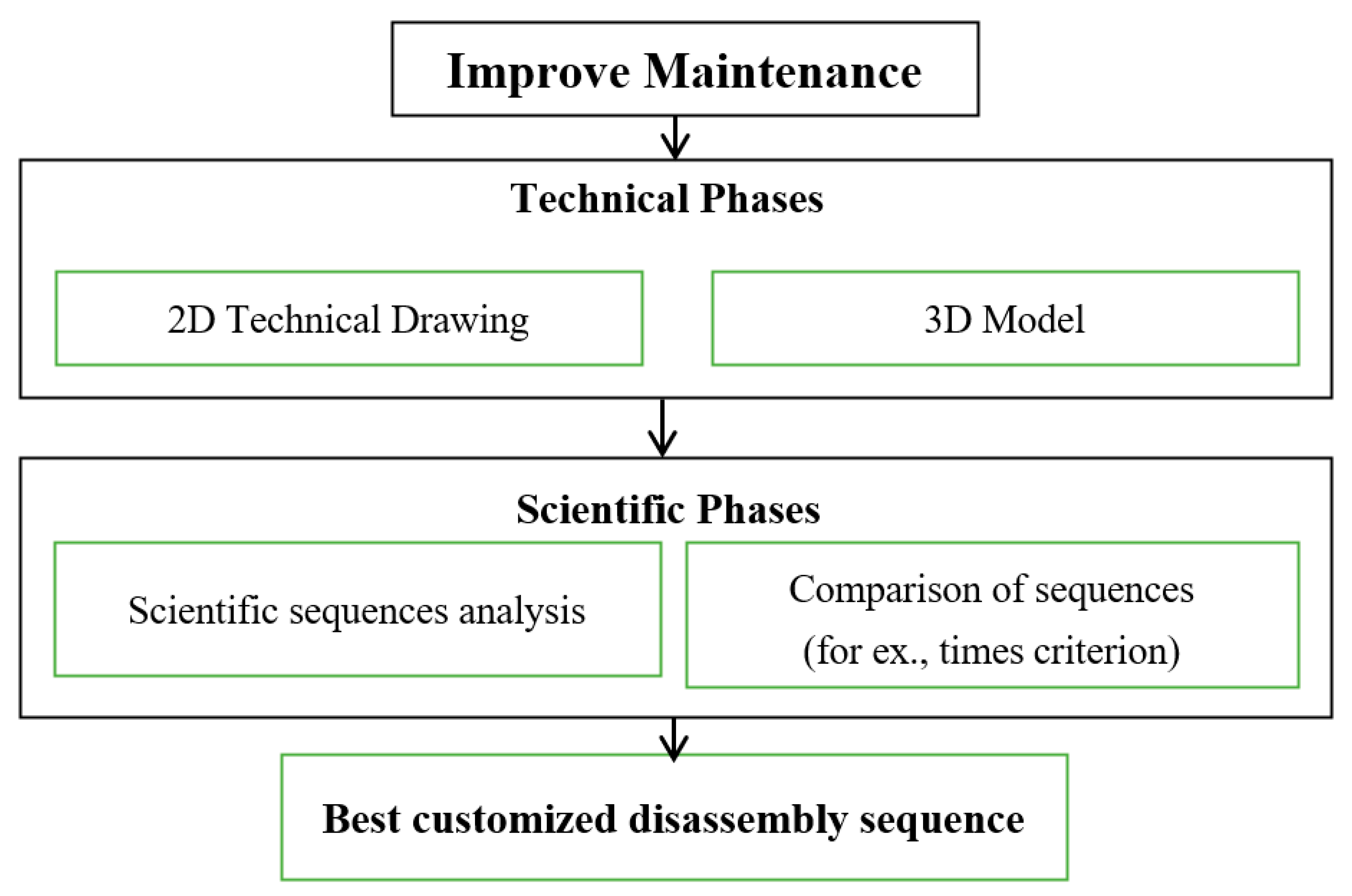
7. Synthetizing the Methodology
Trying to synthetize the whole method developed during the present work, it can be affirmed that
- In order to improve the maintenance of a new mechanical product (for example, a gearbox, or alike), it can be useful to develop a customized disassembly sequence
- Starting from the 2D technical drawing (for example, Figure 1a) of the assembly, it is possible to realize a 3D model of the same object;
- Phases 1 and 2 can be considered the technical phases;
- Shen, the scientific steps start; in the literature, many papers can be found about scientific disassembly sequences, published by scientists all over the world;
- Scientific sequences (i.e., Mitrochev and Yi ones) can be put in comparison choosing a specific criterion, for example the times criterion, as in the presented case study, towards the specific product to be disassembled (i.e., gearbox);
- The best sequence found will be able to be the one chosen for optimize maintenance process.
Other future applications and developments can be also:
- Inventing another disassembly sequence, eventually mixing the best practices of the above studied ones;
- Reproduction a technical disassembly animation in CAD environment;
- Exporting the CAD disassembly animation into Augmented Reality environment, in order to generate a technical innovative user manual for maintenance.
Disassembly issues emerged during the above-mentioned study and process can also impact toward the design process, suggesting to the designer how to optimize the product in order to reduce or augment the number of parts and their relative connections. So, in this sense, DSP (or in general DfD) can be considered part of DfX, just like DfA [31].
8. Conclusions
Keeping into consideration what written in the previous paragraph (i.e., nr. 7), authors followed the new process illustrated in Figure 5.
The results obtained from the calculations, shown in the table, do not allow to fully appreciate the differences between the two techniques used to elaborate the searched disassembly sequence. This is because the times obtained have discrepancies of a few seconds, due to the fact that the algorithms presented have been designed for more complex situations than the geared motor considered.
In the case in question, in fact, there are no significant subgroups that require special precautions in the disassembly approach.
From the point of view of the use of tools, what emerges is the importance of following an order that allows to optimize the use of the tools in such a way as to minimize the changes. In the specific case, the simplicity of the connecting elements of the mechanism in question has significantly facilitated the choice of the disassembly order of the elements within the various levels. This has led to minimizing the change of tools to the strict minimum, making the difference between the two techniques null.
The subgroup approach of the Jianjun technique gave poorly appreciable results compared to the Mitrouchev method since the number of components considered (just under 150 in total), and the structure of the mechanism did not require particular compartments to significantly optimize the disassembly from the point of view of minimum use of time.
However, the theoretical differences in perspective of the two algorithms, almost opposite to each other, are very evident. This shows, as also stated in the introductory phase of the work, that there is no optimal method to apply in order to obtain a disassembly sequence that is a priori the best possible of all.
The choice of the algorithm to be used cannot therefore disregard the omniscient knowledge of the product being considered.
Author Contributions
L.F. Conceptualization, supervision, word draft; A.L. softwares, formal analysis, data curation. All authors have read and agreed to the published version of the manuscript.
Funding
This research received no external funding.
Conflicts of Interest
The authors declare no conflict of interest.
Appendix A

Table A1.
Time calculation with Jianjun method. Take into consideration that the most external dismantling levels focus on the connecting elements, which have no different way of being treated according to the algorithm. They must all be removed and therefore, to avoid redundancy, the first disassembly levels are now omitted. Assume, therefore, to consider the mechanism as it appears at the beginning of level 4 of the previously described algorithm.
| Task No. | Component No. | Task | Tool | EOL Option | Disassembly Force | Material Handling | Requirement of Tools | Accessibility of Joints | Positioning | Total Task | Note | ||||||||
|---|---|---|---|---|---|---|---|---|---|---|---|---|---|---|---|---|---|---|---|
| push/pull operation with hand | twisting and push/pull operation with hand | inter-surface friction | inter-surface wedging | material stiffness | size | weight | symmetry | force exertion | torque exertion | dimension | location | accuracy of tools placement | EOL option: 1 recycling; 2 remanufacturing; 3 reuse | ||||||
| Level 1: external and connecting elements | |||||||||||||||||||
| 458.0 | tot. Level 1 | ||||||||||||||||||
| Level 2: external and connection elements released from level 1 | |||||||||||||||||||
| 228.9 | tot. Level 2 | ||||||||||||||||||
| Level 3: external and connecting elements | |||||||||||||||||||
| 233.5 | tot. Level 3 | ||||||||||||||||||
| Level 4: release of the gear and bush release subassembly | |||||||||||||||||||
| 4.1 | 1 | p. u. | - | 3 | 1 | 0 | 0 | 0 | 0 | 2 | 2.5 | 2.2 | 1 | 0 | 1 | 1 | 1.2 | 12 | remove lower casing |
| 4.2 | gr. 32 | p. u | - | - | 1 | 0 | 0 | 0 | 0 | 3.5 | 2.5 | 2.4 | 1 | 0 | 1 | 1 | 1.2 | 14 | separate gear unit |
| 4.3 | 11 | un | cg | 1 | 0 | 2 | 0 | 0 | 0 | 2 | 2 | 0.8 | 0 | 2 | 1 | 1 | 2 | 13 | remove ring nut |
| 4.4 | 13 | p. u | - | 1 | 0.5 | 0 | 0 | 0 | 0 | 2 | 2 | 0.8 | 1 | 0 | 1 | 1 | 1.2 | 9.5 | remove washer |
| 4.5 | 12 | un | cg | 1 | 0 | 2 | 0 | 0 | 0 | 2 | 2 | 0.8 | 0 | 2 | 1 | 1 | 2 | 13 | remove ring nut |
| 4.6 | 14 | p. u | - | 1 | 0.5 | 0 | 0 | 0 | 0 | 2 | 2 | 0.8 | 1 | 0 | 1 | 1 | 1.2 | 9.5 | remove washer |
| Level 5: junction of the bushing subgroups | |||||||||||||||||||
| 5.1 | 4 | p. u | p. r. | - | 0 | 0 | 5 | 0 | 0 | 3.5 | 2 | 1.2 | 3 | 0 | 1 | 1.6 | 5 | 22 | remove bush |
| 5.2 | gr. 3 | p. u | p. r | - | 0 | 0 | 5 | 0 | 0 | 3.5 | 2 | 1.2 | 3 | 0 | 1 | 1.6 | 5 | 22 | |
| 5.3 | 32 | p. u | - | 3 | 1 | 0 | 0 | 0 | 0 | 3.5 | 2 | 0.8 | 1 | 0 | 1 | 1 | 0.8 | 11 | remove crown |
| 5.4 | 41 | un | pi | 1 | 0 | 1 | 0 | 0 | 0 | 2 | 2 | 0.8 | 0 | 2 | 1 | 1 | 1.2 | 11 | remove bronze bushing grain |
| 5.5 | 41 | un | pi | 1 | 0 | 1 | 0 | 0 | 0 | 2 | 2 | 0.8 | 0 | 2 | 1 | 1 | 1.2 | 11 | remove bronze bushing grain |
| 5.6 | 35 | un | cd | 1 | 0 | 2 | 0 | 0 | 0 | 2 | 2 | 0.8 | 0 | 2 | 1 | 1 | 1.2 | 12 | remove nut M10 |
| 5.7 | 35 | un | cd | 1 | 0 | 2 | 0 | 0 | 0 | 2 | 2 | 0.8 | 0 | 2 | 1 | 1 | 1.2 | 12 | remove nut M10 |
| 5.8 | 35 | un | cd | 1 | 0 | 2 | 0 | 0 | 0 | 2 | 2 | 0.8 | 0 | 2 | 1 | 1 | 1.2 | 12 | remove nut M10 |
| 5.9 | 35 | un | cd | 1 | 0 | 2 | 0 | 0 | 0 | 2 | 2 | 0.8 | 0 | 2 | 1 | 1 | 1.2 | 12 | remove nut M10 |
| 5.10 | 35 | un | cd | 1 | 0 | 2 | 0 | 0 | 0 | 2 | 2 | 0.8 | 0 | 2 | 1 | 1 | 1.2 | 12 | remove nut M10 |
| 5.11 | 35 | un | cd | 1 | 0 | 2 | 0 | 0 | 0 | 2 | 2 | 0.8 | 0 | 2 | 1 | 1 | 1.2 | 12 | remove nut M10 |
| 5.12 | 35 | un | cd | 1 | 0 | 2 | 0 | 0 | 0 | 2 | 2 | 0.8 | 0 | 2 | 1 | 1 | 1.2 | 12 | remove nut M10 |
| 5.13 | 35 | un | cd | 1 | 0 | 2 | 0 | 0 | 0 | 2 | 2 | 0.8 | 0 | 2 | 1 | 1 | 1.2 | 12 | remove nut M10 |
| Level 6: removal of the upper casing | |||||||||||||||||||
| 6.1 | 2 | p. u | - | 3 | 1 | 0 | 0 | 0 | 0 | 2 | 2.5 | 2.4 | 1 | 0 | 1 | 1 | 1.2 | 12 | remove top cover |
| 6.2 | 34 | un | - | 1 | 0.5 | 0 | 0 | 0 | 0 | 2 | 2 | 0.8 | 1 | 0 | 1 | 1 | 1.2 | 9.5 | remove screw M10 |
| 6.3 | 34 | un | - | 1 | 0.5 | 0 | 0 | 0 | 0 | 2 | 2 | 0.8 | 1 | 0 | 1 | 1 | 1.2 | 9.5 | remove screw M10 |
| 6.4 | 34 | un | - | 1 | 0.5 | 0 | 0 | 0 | 0 | 2 | 2 | 0.8 | 1 | 0 | 1 | 1 | 1.2 | 9.5 | remove screw M10 |
| 6.5 | 34 | un | - | 1 | 0.5 | 0 | 0 | 0 | 0 | 2 | 2 | 0.8 | 1 | 0 | 1 | 1 | 1.2 | 9.5 | remove screw M10 |
| 6.6 | 34 | un | - | 1 | 0.5 | 0 | 0 | 0 | 0 | 2 | 2 | 0.8 | 1 | 0 | 1 | 1 | 1.2 | 9.5 | remove screw M10 |
| 6.7 | 34 | un | - | 1 | 0.5 | 0 | 0 | 0 | 0 | 2 | 2 | 0.8 | 1 | 0 | 1 | 1 | 1.2 | 9.5 | remove screw M10 |
| 6.8 | 34 | un | - | 1 | 0.5 | 0 | 0 | 0 | 0 | 2 | 2 | 0.8 | 1 | 0 | 1 | 1 | 1.2 | 9.5 | remove screw M10 |
| 6.9 | 34 | un | - | 1 | 0.5 | 0 | 0 | 0 | 0 | 2 | 2 | 0.8 | 1 | 0 | 1 | 1 | 1.2 | 9.5 | remove screw M10 |
| 6.10 | 42 | p. u | p. r | 3 | 0 | 0 | 5 | 0 | 0 | 2 | 2 | 0.8 | 3 | 0 | 1 | 1 | 5 | 20 | remove bushing |
| 6.11 | 42 | p. u | p. r | 3 | 0 | 0 | 5 | 0 | 0 | 2 | 2 | 0.8 | 3 | 0 | 1 | 1 | 5 | 20 | remove bushing |
| 6.12 | 6 | p. u | p. r | 1 | 0 | 0 | 5 | 0 | 0 | 2 | 2 | 0.8 | 3 | 0 | 1 | 1 | 5 | 20 | remove bearing |
| 6.13 | 7 | p. u | p. r | 1 | 0 | 0 | 5 | 0 | 0 | 2 | 2 | 0.8 | 3 | 0 | 1.6 | 2 | 5 | 21 | remove bearing |
| - | 17 | - | - | 3 | - | - | - | - | - | - | - | - | - | - | - | - | - | - | bearing spacer |
| - | 3 | - | - | 3 | - | - | - | - | - | - | - | - | - | - | - | - | - | - | bush |
| 6.14 | 18 | p. u | pi | 3 | 0 | 0 | 3 | 0 | 0 | 2 | 2 | 0.8 | 3 | 0 | 1 | 1 | 2 | 15 | remove spacer from the globoid screw |
| Level 7: junction of the last parts | |||||||||||||||||||
| 7.1 | 33 | p. u | p. r | 3 | 0 | 0 | 5 | 0 | 0 | 3.5 | 2 | 1.2 | 3 | 0 | 1 | 1 | 5 | 22 | remove crown disc |
| 7.2 | 6 | p. u | p. r | 1 | 0 | 0 | 5 | 0 | 0 | 2 | 2 | 0.8 | 3 | 0 | 1 | 1 | 5 | 20 | remove bearing |
| 7.3 | 24 | p. u | - | 3 | 1 | 0 | 0 | 0 | 0 | 2 | 2 | 0.8 | 1 | 0 | 1 | 1 | 1.2 | 10 | remove spacer |
| Level 8: total disassembly | |||||||||||||||||||
| 8.1 | 6 | p. u. | p. r | 1 | 0 | 0 | 5 | 0 | 0 | 2 | 2 | 0.8 | 3 | 0 | 1 | 1 | 5 | 20 | remove bearing |
| 10 | 3 | ||||||||||||||||||
| 8.2 | 37 | p. u. | - | 1 | 0.5 | 0 | 0 | 0 | 0 | 2 | 2 | 0.8 | 1 | 0 | 1 | 2 | 1.2 | 11 | remove tongue |
| 44 | 3 | shaft | |||||||||||||||||
| tool changes: | 12 | total disassembly time (TMU): | 1429.7 | ||||||||||||||||
| (TMUs) × 10 × 0.036 = (sec) | 514.692 | ||||||||||||||||||
| 8 min 35 sec | |||||||||||||||||||
Appendix B
Table A2.
Time calculation with Mitrouchev method.
| Task No. | Component No. | Task | Tool | EOL Option | Disassembly Force | Material Handling | Requirement of Tools | Accessibility of Joints | Positioning | Total Task | Note | ||||||||||||||||
|---|---|---|---|---|---|---|---|---|---|---|---|---|---|---|---|---|---|---|---|---|---|---|---|---|---|---|---|
| push/pull operation with hand | twisting and push/pull operation with hand | inter-surface friction | inter-surface wedging | material stiffness | size | weight | symmetry | force exertion | torque exertion | dimension | location | accuracy of tools placement | EOL option: 1 recycling; 2 remanufacturing; 3 reuse | ||||||||||||||
| Level 1: external and connecting elements | |||||||||||||||||||||||||||
| 1.1 | 20 | un | cd | 1 | 0 | 2 | 0 | 0 | 0 | 2 | 2 | 0.8 | 0 | 2 | 1 | 1 | 1.2 | 12 | remove nut M8 | ||||||||
| 1.2 | 20 | un | cd | 1 | 0 | 2 | 0 | 0 | 0 | 2 | 2 | 0.8 | 0 | 2 | 1 | 1 | 1.2 | 12 | remove nut M8 | ||||||||
| 1.3 | 20 | un | cd | 1 | 0 | 2 | 0 | 0 | 0 | 2 | 2 | 0.8 | 0 | 2 | 1 | 1 | 1.2 | 12 | remove nut M8 | ||||||||
| 1.4 | 20 | un | cd | 1 | 0 | 2 | 0 | 0 | 0 | 2 | 2 | 0.8 | 0 | 2 | 1 | 1 | 1.2 | 12 | remove nut M8 | ||||||||
| 1.5 | 20 | un | cd | 1 | 0 | 2 | 0 | 0 | 0 | 2 | 2 | 0.8 | 0 | 2 | 1 | 1 | 1.2 | 12 | remove nut M8 | ||||||||
| 1.6 | 20 | un | cd | 1 | 0 | 2 | 0 | 0 | 0 | 2 | 2 | 0.8 | 0 | 2 | 1 | 1 | 1.2 | 12 | remove nut M8 | ||||||||
| 1.7 | 20 | un | cd | 1 | 0 | 2 | 0 | 0 | 0 | 2 | 2 | 0.8 | 0 | 2 | 1 | 1 | 1.2 | 12 | remove nut M8 | ||||||||
| 1.8 | 20 | un | cd | 1 | 0 | 2 | 0 | 0 | 0 | 2 | 2 | 0.8 | 0 | 2 | 1 | 1 | 1.2 | 12 | remove nut M8 | ||||||||
| 1.9 | 20 | un | cd | 1 | 0 | 2 | 0 | 0 | 0 | 2 | 2 | 0.8 | 0 | 2 | 1 | 1 | 1.2 | 12 | remove nut M8 | ||||||||
| 1.10 | 20 | un | cd | 1 | 0 | 2 | 0 | 0 | 0 | 2 | 2 | 0.8 | 0 | 2 | 1 | 1 | 1.2 | 12 | remove nut M8 | ||||||||
| 1.11 | 20 | un | cd | 1 | 0 | 2 | 0 | 0 | 0 | 2 | 2 | 0.8 | 0 | 2 | 1 | 1 | 1.2 | 12 | remove nut M8 | ||||||||
| 1.12 | 20 | un | cd | 1 | 0 | 2 | 0 | 0 | 0 | 2 | 2 | 0.8 | 0 | 2 | 1 | 1 | 1.2 | 12 | remove nut M8 | ||||||||
| 1.13 | 25 | un | cd | 1 | 0 | 2 | 0 | 0 | 0 | 2 | 2 | 0.8 | 0 | 2 | 1 | 1 | 1.2 | 12 | remove nut M16 | ||||||||
| 1.14 | 25 | un | cd | 1 | 0 | 2 | 0 | 0 | 0 | 2 | 2 | 0.8 | 0 | 2 | 1 | 1 | 1.2 | 12 | remove nut M16 | ||||||||
| 1.15 | 25 | un | cd | 1 | 0 | 2 | 0 | 0 | 0 | 2 | 2 | 0.8 | 0 | 2 | 1 | 1 | 1.2 | 12 | remove nut M16 | ||||||||
| 1.16 | 25 | un | cd | 1 | 0 | 2 | 0 | 0 | 0 | 2 | 2 | 0.8 | 0 | 2 | 1 | 1 | 1.2 | 12 | remove nut M16 | ||||||||
| 1.17 | 27 | un | cd | 1 | 0 | 2 | 0 | 0 | 0 | 2 | 2 | 0.8 | 0 | 2 | 1 | 1 | 1.2 | 12 | remove nut M12 | ||||||||
| 1.18 | 27 | un | cd | 1 | 0 | 2 | 0 | 0 | 0 | 2 | 2 | 0.8 | 0 | 2 | 1 | 1 | 1.2 | 12 | remove nut M12 | ||||||||
| 1.19 | 27 | un | cd | 1 | 0 | 2 | 0 | 0 | 0 | 2 | 2 | 0.8 | 0 | 2 | 1 | 1 | 1.2 | 12 | remove nut M12 | ||||||||
| 1.20 | 27 | un | cd | 1 | 0 | 2 | 0 | 0 | 0 | 2 | 2 | 0.8 | 0 | 2 | 1 | 1 | 1.2 | 12 | remove nut M12 | ||||||||
| 1.21 | 29 | un | cd | 1 | 0 | 2 | 0 | 0 | 0 | 2 | 2 | 0.8 | 0 | 2 | 1 | 1 | 1.2 | 12 | remove oil cap | ||||||||
| 1.22 | 30 | pu | - | 0 | 0.5 | 0 | 0 | 0 | 0 | 2 | 2 | 0.8 | 1 | 0 | 1 | 1 | 1.2 | 9.5 | remove gasket | ||||||||
| 1.23 | 29 | un | cd | 1 | 0 | 2 | 0 | 0 | 0 | 2 | 2 | 0.8 | 0 | 2 | 1 | 1 | 1.2 | 12 | remove oil cap | ||||||||
| 1.24 | 30 | pu | - | 0 | 0.5 | 0 | 0 | 0 | 0 | 2 | 2 | 0.8 | 1 | 0 | 1 | 1 | 1.2 | 9.5 | remove gasket | ||||||||
| 1.25 | 23 | un | c. b. | 1 | 0 | 2 | 0 | 0 | 0 | 2 | 2 | 0.8 | 0 | 2 | 1 | 1 | 1.2 | 12 | remove screw TSB M8 | ||||||||
| 1.26 | 23 | un | c. b. | 1 | 0 | 2 | 0 | 0 | 0 | 2 | 2 | 0.8 | 0 | 2 | 1 | 1 | 1.2 | 12 | remove screw TSB M8 | ||||||||
| 1.27 | 38 | un | cd | 1 | 0 | 2 | 0 | 0 | 0 | 2 | 2 | 0.8 | 0 | 2 | 1 | 1 | 1.2 | 12 | remove screw M6 | ||||||||
| 1.28 | 45 | pu | - | 1 | 0.5 | 0 | 0 | 0 | 0 | 2 | 2 | 0.8 | 1 | 0 | 1 | 1 | 1.2 | 9.5 | remove rosette A6 | ||||||||
| 1.29 | 38 | un | cd | 1 | 0 | 2 | 0 | 0 | 0 | 2 | 2 | 0.8 | 0 | 2 | 1 | 1 | 1.2 | 12 | remove screw M6 | ||||||||
| 1.30 | 45 | pu | - | 1 | 0.5 | 0 | 0 | 0 | 0 | 2 | 2 | 0.8 | 1 | 0 | 1 | 1 | 1.2 | 9.5 | remove rosette A6 | ||||||||
| 1.31 | 38 | un | cd | 1 | 0 | 2 | 0 | 0 | 0 | 2 | 2 | 0.8 | 0 | 2 | 1 | 1 | 1.2 | 12 | remove screw M6 | ||||||||
| 1.32 | 45 | pu | - | 1 | 0.5 | 0 | 0 | 0 | 0 | 2 | 2 | 0.8 | 1 | 0 | 1 | 1 | 1.2 | 9.5 | remove rosette A6 | ||||||||
| 1.33 | 38 | un | cd | 1 | 0 | 2 | 0 | 0 | 0 | 2 | 2 | 0.8 | 0 | 2 | 1 | 1 | 1.2 | 12 | remove screw M6 | ||||||||
| 1.34 | 45 | p. u. | - | 1 | 0.5 | 0 | 0 | 0 | 0 | 2 | 2 | 0.8 | 1 | 0 | 1 | 1 | 1.2 | 9.5 | remove rosette A6 | ||||||||
| 1.35 | 38 | Un | cd | 1 | 0 | 2 | 0 | 0 | 0 | 2 | 2 | 0.8 | 0 | 2 | 1 | 1 | 1.2 | 12 | remove screw M6 | ||||||||
| 1.36 | 45 | p. u. | - | 1 | 0.5 | 0 | 0 | 0 | 0 | 2 | 2 | 0.8 | 1 | 0 | 1 | 1 | 1.2 | 9.5 | remove rosette A6 | ||||||||
| 1.37 | 38 | un | cd | 1 | 0 | 2 | 0 | 0 | 0 | 2 | 2 | 0.8 | 0 | 2 | 1 | 1 | 1.2 | 12 | remove screw M6 | ||||||||
| 1.38 | 45 | p. u. | - | 1 | 0.5 | 0 | 0 | 0 | 0 | 2 | 2 | 0.8 | 1 | 0 | 1 | 1 | 1.2 | 9.5 | remove rosette A6 | ||||||||
| 1.39 | 36 | un | - | 1 | 0 | 2 | 0 | 0 | 0 | 2 | 2 | 0.8 | 0 | 1 | 1 | 1 | 1.2 | 11 | unscrew grease nipple | ||||||||
| 1.40 | 36 | un | - | 1 | 0 | 2 | 0 | 0 | 0 | 2 | 2 | 0.8 | 0 | 1 | 1 | 1 | 1.2 | 11 | unscrew grease nipple | ||||||||
| Level 2: external and connection elements released from level 1 | |||||||||||||||||||||||||||
| 2.1 | 28 | p. u. | - | 1 | 0.5 | 0 | 0 | 0 | 0 | 2 | 2 | 0.8 | 1 | 0 | 1 | 1 | 1.2 | 9.5 | remove screw M12 | ||||||||
| 2.2 | 28 | p. u. | - | 1 | 0.5 | 0 | 0 | 0 | 0 | 2 | 2 | 0.8 | 1 | 0 | 1 | 1 | 1.2 | 9.5 | remove screw M12 | ||||||||
| 2.3 | 28 | p. u. | - | 1 | 0.5 | 0 | 0 | 0 | 0 | 2 | 2 | 0.8 | 1 | 0 | 1 | 1 | 1.2 | 9.5 | remove screw M12 | ||||||||
| 2.4 | 28 | p. u. | - | 1 | 0.5 | 0 | 0 | 0 | 0 | 2 | 2 | 0.8 | 1 | 0 | 1 | 1 | 1.2 | 9.5 | remove screw M12 | ||||||||
| 2.5 | 39 | p. u. | - | 1 | 0.5 | 0 | 0 | 0 | 0 | 2 | 2 | 0.8 | 1 | 0 | 1 | 1 | 1.2 | 9.5 | remove rosette A16 | ||||||||
| 2.6 | 39 | p. u. | - | 1 | 0.5 | 0 | 0 | 0 | 0 | 2 | 2 | 0.8 | 1 | 0 | 1 | 1 | 1.2 | 9.5 | remove rosetteA16 | ||||||||
| 2.7 | 39 | p. u. | - | 1 | 0.5 | 0 | 0 | 0 | 0 | 2 | 2 | 0.8 | 1 | 0 | 1 | 1 | 1.2 | 9.5 | remove rosette A16 | ||||||||
| 2.8 | 39 | p. u. | - | 1 | 0,5 | 0 | 0 | 0 | 0 | 2 | 2 | 0.8 | 1 | 0 | 1 | 1 | 1.2 | 9.5 | remove rosette A16 | ||||||||
| 2.9 | 15 | p. u. | - | 1 | 0.5 | 0 | 0 | 0 | 0 | 2 | 2 | 0.8 | 1 | 0 | 1 | 1 | 1.2 | 9.5 | remove plate | ||||||||
| 2.10 | 16 | p. u. | - | 1 | 0.5 | 0 | 0 | 0 | 0 | 2 | 2 | 0.8 | 1 | 0 | 1 | 1 | 1.2 | 9.5 | remove plate | ||||||||
| 2.11 | 21 | p. u. | - | 1 | 0.5 | 0 | 0 | 0 | 0 | 2 | 2 | 0.8 | 1 | 0 | 1 | 1 | 1,2 | 9,5 | remove rosette A8 | ||||||||
| 2.12 | 21 | p. u. | - | 1 | 0.5 | 0 | 0 | 0 | 0 | 2 | 2 | 0.8 | 1 | 0 | 1 | 1 | 1,2 | 9,5 | remove rosette A8 | ||||||||
| 2.13 | 21 | p. u. | - | 1 | 0.5 | 0 | 0 | 0 | 0 | 2 | 2 | 0.8 | 1 | 0 | 1 | 1 | 1,2 | 9,5 | remove rosette A8 | ||||||||
| 2.14 | 21 | p. u. | - | 1 | 0.5 | 0 | 0 | 0 | 0 | 2 | 2 | 0.8 | 1 | 0 | 1 | 1 | 1,2 | 9,5 | remove rosetteA8 | ||||||||
| 2.15 | 21 | p. u. | - | 1 | 0.5 | 0 | 0 | 0 | 0 | 2 | 2 | 0.8 | 1 | 0 | 1 | 1 | 1,2 | 9,5 | remove rosette A8 | ||||||||
| 2.16 | 21 | p. u. | - | 1 | 0.5 | 0 | 0 | 0 | 0 | 2 | 2 | 0.8 | 1 | 0 | 1 | 1 | 1,2 | 9,5 | remove rosette A8 | ||||||||
| 2.17 | 21 | p. u. | - | 1 | 0.5 | 0 | 0 | 0 | 0 | 2 | 2 | 0.8 | 1 | 0 | 1 | 1 | 1,2 | 9,5 | remove rosette A8 | ||||||||
| 2.18 | 21 | p. u. | - | 1 | 0.5 | 0 | 0 | 0 | 0 | 2 | 2 | 0.8 | 1 | 0 | 1 | 1 | 1.2 | 9.5 | remove rosette A8 | ||||||||
| 2.19 | 21 | p. u. | - | 1 | 0.5 | 0 | 0 | 0 | 0 | 2 | 2 | 0.8 | 1 | 0 | 1 | 1 | 1.2 | 9.5 | remove rosette A8 | ||||||||
| 2.20 | 21 | p. u. | - | 1 | 0.5 | 0 | 0 | 0 | 0 | 2 | 2 | 0.8 | 1 | 0 | 1 | 1 | 1.2 | 9.5 | remove rosette A8 | ||||||||
| 2.21 | 21 | p. u. | - | 1 | 0.5 | 0 | 0 | 0 | 0 | 2 | 2 | 0.8 | 1 | 0 | 1 | 1 | 1.2 | 9.5 | remove rosette A8 | ||||||||
| 2.22 | 21 | p. u. | - | 1 | 0.5 | 0 | 0 | 0 | 0 | 2 | 2 | 0.8 | 1 | 0 | 1 | 1 | 1.2 | 9.5 | remove rosette A8 | ||||||||
| 2.23 | 5 | p. u. | - | 3 | 1 | 0 | 0 | 0 | 0 | 2 | 2 | 1.2 | 1 | 0 | 1 | 1 | 1.2 | 10 | remove cover | ||||||||
| 2.24 | 40 | p. u. | - | 3 | 0.5 | 0 | 0 | 0 | 0 | 2 | 2 | 0.8 | 1 | 0 | 1 | 1 | 1.2 | 9.5 | remove little cover | ||||||||
| Level 3: external elements | |||||||||||||||||||||||||||
| 3.1 | 8 | un | - | 3 | 0 | 2 | 0 | 0 | 0 | 2 | 2 | 0.8 | 1 | 0 | 1 | 1 | 1.2 | 11 | remove cap | ||||||||
| 3.2 | 19 | p. u. | - | 1 | 0.5 | 0 | 0 | 0 | 0 | 2 | 2 | 0.8 | 1 | 0 | 1 | 1 | 1.2 | 9.5 | remove gasket | ||||||||
| 3.3 | 9 | un | - | 3 | 0 | 2 | 0 | 0 | 0 | 2 | 2 | 0.8 | 1 | 0 | 1 | 1 | 1.2 | 11 | remove cap | ||||||||
| 3.4 | 31 | p. u. | - | 1 | 1 | 0 | 0 | 0 | 0 | 2 | 2 | 0.8 | 1 | 0 | 1 | 1 | 1.2 | 10 | remove gasket | ||||||||
| 3.5 | 22 | un | e. s. | 1 | 0 | 2 | 0 | 0 | 0 | 2 | 2 | 0.8 | 0 | 2 | 1 | 1 | 1.2 | 12 | remove stud screw | ||||||||
| 3.6 | 22 | un | e. s. | 1 | 0 | 2 | 0 | 0 | 0 | 2 | 2 | 0.8 | 0 | 2 | 1 | 1 | 1.2 | 12 | remove stud screw | ||||||||
| 3.7 | 22 | un | e. s. | 1 | 0 | 2 | 0 | 0 | 0 | 2 | 2 | 0.8 | 0 | 2 | 1 | 1 | 1.2 | 12 | remove stud screw | ||||||||
| 3.8 | 22 | un | e. s. | 1 | 0 | 2 | 0 | 0 | 0 | 2 | 2 | 0.8 | 0 | 2 | 1 | 1 | 1.2 | 12 | remove stud screw | ||||||||
| 3.9 | 22 | un | e. s. | 1 | 0 | 2 | 0 | 0 | 0 | 2 | 2 | 0.8 | 0 | 2 | 1 | 1 | 1.2 | 12 | remove stud screw | ||||||||
| 3.10 | 22 | un | e. s. | 1 | 0 | 2 | 0 | 0 | 0 | 2 | 2 | 0.8 | 0 | 2 | 1 | 1 | 1.2 | 12 | remove stud screw | ||||||||
| 3.11 | 22 | un | e. s. | 1 | 0 | 2 | 0 | 0 | 0 | 2 | 2 | 0.8 | 0 | 2 | 1 | 1 | 1.2 | 12 | remove stud screw | ||||||||
| 3.12 | 22 | un | e. s. | 1 | 0 | 2 | 0 | 0 | 0 | 2 | 2 | 0.8 | 0 | 2 | 1 | 1 | 1.2 | 12 | remove stud screw | ||||||||
| 3.13 | 22 | un | e. s. | 1 | 0 | 2 | 0 | 0 | 0 | 2 | 2 | 0.8 | 0 | 2 | 1 | 1 | 1.2 | 12 | remove stud screw | ||||||||
| 3.14 | 22 | un | e. s. | 1 | 0 | 2 | 0 | 0 | 0 | 2 | 2 | 0.8 | 0 | 2 | 1 | 1 | 1.2 | 12 | remove stud screw | ||||||||
| 3.15 | 22 | un | e. s. | 1 | 0 | 2 | 0 | 0 | 0 | 2 | 2 | 0.8 | 0 | 2 | 1 | 1 | 1.2 | 12 | remove stud screw | ||||||||
| 3.16 | 22 | un | e. s. | 1 | 0 | 2 | 0 | 0 | 0 | 2 | 2 | 0.8 | 0 | 2 | 1 | 1 | 1.2 | 12 | remove stud screw | ||||||||
| 3.17 | 26 | un | e. s. | 1 | 0 | 2 | 0 | 0 | 0 | 2 | 2 | 0.8 | 0 | 2 | 1 | 1 | 1.2 | 12 | remove stud screw | ||||||||
| 3.18 | 26 | un | e. s. | 1 | 0 | 2 | 0 | 0 | 0 | 2 | 2 | 0.8 | 0 | 2 | 1 | 1 | 1.2 | 12 | remove stud screw | ||||||||
| 3.19 | 26 | un | e. s. | 1 | 0 | 2 | 0 | 0 | 0 | 2 | 2 | 0.8 | 0 | 2 | 1 | 1 | 1.2 | 12 | remove stud screw | ||||||||
| 3.20 | 26 | un | e. s. | 1 | 0 | 2 | 0 | 0 | 0 | 2 | 2 | 0.8 | 0 | 2 | 1 | 1 | 1.2 | 12 | remove stud screw | ||||||||
| Level 4: decoupling of the mechanism | |||||||||||||||||||||||||||
| 4.1 | 11 | un | cg | 1 | 0 | 2 | 0 | 0 | 0 | 2 | 2 | 0.8 | 0 | 2 | 1 | 1 | 2 | 13 | remove ring nut | ||||||||
| 4.2 | 12 | un | cg | 1 | 0 | 2 | 0 | 0 | 0 | 2 | 2 | 0.8 | 0 | 2 | 1 | 1 | 2 | 13 | remove ring nut | ||||||||
| 4.3 | 1 | p. u. | - | 3 | 1 | 0 | 0 | 0 | 0 | 2 | 2.5 | 2.2 | 1 | 0 | 1 | 1 | 1.2 | 12 | remove lower casing | ||||||||
| 4.4 | gr. 32 | p. u. | - | - | 1 | 0 | 0 | 0 | 0 | 3.5 | 2.5 | 2.4 | 1 | 0 | 1 | 1 | 1.2 | 14 | remove gear assembly | ||||||||
| Level 5: gear unit and screw assembly | |||||||||||||||||||||||||||
| 5.1 | 35 | un | cd | 1 | 0 | 2 | 0 | 0 | 0 | 2 | 2 | 0.8 | 0 | 2 | 1 | 1 | 1.2 | 12 | remove nut M10 | ||||||||
| 5.2 | 35 | un | cd | 1 | 0 | 2 | 0 | 0 | 0 | 2 | 2 | 0.8 | 0 | 2 | 1 | 1 | 1.2 | 12 | remove nut M10 | ||||||||
| 5.3 | 35 | un | cd | 1 | 0 | 2 | 0 | 0 | 0 | 2 | 2 | 0.8 | 0 | 2 | 1 | 1 | 1.2 | 12 | remove nut M10 | ||||||||
| 5.4 | 35 | un | cd | 1 | 0 | 2 | 0 | 0 | 0 | 2 | 2 | 0.8 | 0 | 2 | 1 | 1 | 1.2 | 12 | remove nut M10 | ||||||||
| 5.5 | 35 | un | cd | 1 | 0 | 2 | 0 | 0 | 0 | 2 | 2 | 0.8 | 0 | 2 | 1 | 1 | 1.2 | 12 | remove nut M10 | ||||||||
| 5.6 | 35 | un | cd | 1 | 0 | 2 | 0 | 0 | 0 | 2 | 2 | 0.8 | 0 | 2 | 1 | 1 | 1.2 | 12 | remove nut M10 | ||||||||
| 5.7 | 35 | un | cd | 1 | 0 | 2 | 0 | 0 | 0 | 2 | 2 | 0.8 | 0 | 2 | 1 | 1 | 1.2 | 12 | remove nut M10 | ||||||||
| 5.8 | 35 | un | cd | 1 | 0 | 2 | 0 | 0 | 0 | 2 | 2 | 0.8 | 0 | 2 | 1 | 1 | 1.2 | 12 | remove nut M10 | ||||||||
| 5.9 | 41 | un | pi | 1 | 0 | 1 | 0 | 0 | 0 | 2 | 2 | 0.8 | 0 | 2 | 1 | 1 | 1.2 | 12 | remove bronze bushing grain | ||||||||
| 5.10 | 41 | un | pi | 1 | 0 | 1 | 0 | 0 | 0 | 2 | 2 | 0.8 | 0 | 2 | 1 | 1 | 1.2 | 12 | remove bronze bushing grain | ||||||||
| 5.11 | 13 | un | - | 1 | 0 | 2 | 0 | 0 | 0 | 2 | 2 | 0.8 | 0 | 2 | 1 | 1 | 1.2 | 12 | remove washer | ||||||||
| 5.12 | 14 | un | - | 1 | 0 | 2 | 0 | 0 | 0 | 2 | 2 | 0.8 | 0 | 2 | 1 | 1 | 1.2 | 12 | remove washer | ||||||||
| Level 6: gear unit and screw assembly | |||||||||||||||||||||||||||
| 6.1 | 34 | un | - | 1 | 0.5 | 0 | 0 | 0 | 0 | 2 | 2 | 0.8 | 1 | 0 | 1 | 1 | 1.2 | 9.5 | remove screw M10 | ||||||||
| 6.2 | 34 | un | - | 1 | 0.5 | 0 | 0 | 0 | 0 | 2 | 2 | 0.8 | 1 | 0 | 1 | 1 | 1.2 | 9.5 | remove screw M10 | ||||||||
| 6.3 | 34 | un | - | 1 | 0.5 | 0 | 0 | 0 | 0 | 2 | 2 | 0.8 | 1 | 0 | 1 | 1 | 1.2 | 9.5 | remove screw M10 | ||||||||
| 6.4 | 34 | un | - | 1 | 0.5 | 0 | 0 | 0 | 0 | 2 | 2 | 0.8 | 1 | 0 | 1 | 1 | 1.2 | 9.5 | remove screw M10 | ||||||||
| 6.5 | 34 | un | - | 1 | 0.5 | 0 | 0 | 0 | 0 | 2 | 2 | 0.8 | 1 | 0 | 1 | 1 | 1.2 | 9.5 | remove screw M10 | ||||||||
| 6.6 | 34 | un | - | 1 | 0.5 | 0 | 0 | 0 | 0 | 2 | 2 | 0.8 | 1 | 0 | 1 | 1 | 1.2 | 9.5 | remove screw M10 | ||||||||
| 6.7 | 34 | un | - | 1 | 0.5 | 0 | 0 | 0 | 0 | 2 | 2 | 0.8 | 1 | 0 | 1 | 1 | 1.2 | 9.5 | remove screw M10 | ||||||||
| 6.8 | 34 | un | - | 1 | 0.5 | 0 | 0 | 0 | 0 | 2 | 2 | 0.8 | 1 | 0 | 1 | 1 | 1.2 | 9.5 | remove screw M10 | ||||||||
| 6.9 | 42 | p. u. | p. r. | 3 | 0 | 0 | 5 | 0 | 0 | 2 | 2 | 0.8 | 3 | 0 | 1 | 1 | 5 | 19.8 | remove bushing | ||||||||
| 6.10 | 42 | p. u. | p. r. | 3 | 0 | 0 | 5 | 0 | 0 | 2 | 2 | 0.8 | 3 | 0 | 1 | 1 | 5 | 19.8 | remove bushing | ||||||||
| 6.11 | 4 | p. u. | p. r. | 3 | 0 | 0 | 5 | 0 | 0 | 2 | 2 | 0.8 | 3 | 0 | 1 | 1 | 5 | 20 | remove bush | ||||||||
| Level 7: upper casing junction | |||||||||||||||||||||||||||
| 7.1 | 2 | p. u. | - | 3 | 1 | 0 | 0 | 0 | 0 | 2 | 2.5 | 2.4 | 1 | 0 | 1 | 1 | 1.2 | 12 | remove top cover | ||||||||
| 7.2 | 32 | p. u. | - | 3 | 1 | 0 | 0 | 0 | 0 | 3.5 | 2 | 1.2 | 1 | 0 | 1 | 1 | 1.2 | 12 | remove crown | ||||||||
| 7.3 | gr. Buss. 3 | p. u. | p. r. | - | 0 | 0 | 5 | 0 | 0 | 2 | 2 | 1.2 | 3 | 0 | 1 | 1 | 5 | 20 | remove bushing assembly 3 | ||||||||
| Level 8: release of last parts | |||||||||||||||||||||||||||
| 8.1 | 33 | p. u.. | p. r. | 3 | 0 | 0 | 5 | 0 | 0 | 3.5 | 2 | 1.2 | 3 | 0 | 1 | 1 | 5 | 21.7 | remove crown disc | ||||||||
| 8.2 | 6 | p. u. | p. r. | 1 | 0 | 0 | 5 | 0 | 0 | 2 | 2 | 0.8 | 3 | 0 | 1 | 1 | 5 | 20 | remove bearing | ||||||||
| 8.3 | 3 | p. u. | p. r. | 3 | 0 | 0 | 5 | 0 | 0 | 2 | 2 | 0.8 | 3 | 0 | 1 | 1 | 5 | 20 | separate bush and bearing | ||||||||
| 8.4 | 18 | p. u. | pi | 3 | 0 | 0 | 3 | 0 | 0 | 2 | 2 | 0.8 | 3 | 0 | 1 | 1 | 2 | 15 | remove spacer from the globoid screw | ||||||||
| Level 9: release of last pieces | |||||||||||||||||||||||||||
| 9.1 | 37 | p. u. | - | 1 | 0.5 | 0 | 0 | 0 | 0 | 2 | 2 | 0.8 | 1 | 0 | 1 | 2 | 1.2 | 11 | remove tongue | ||||||||
| 44 | 3 | shaft | |||||||||||||||||||||||||
| 9.2 | 17 | p. u. | pi | 3 | 0 | 0 | 3 | 0 | 0 | 2 | 2 | 0.8 | 2 | 0 | 1 | 2 | 2 | 15 | remove spacer from bearing | ||||||||
| - | 7 | - | - | 1 | - | - | - | - | - | - | - | - | - | - | - | - | - | - | bearing | ||||||||
| 9.3 | 6 | p. u. | p. r. | 1 | 0 | 0 | 5 | 0 | 0 | 2 | 2 | 0.8 | 3 | 0 | 1 | 1 | 5 | 20 | remove bearing | ||||||||
| 9.4 | 24 | p. u. | - | 3 | 1 | 0 | 0 | 0 | 0 | 2 | 2 | 0.8 | 1 | 0 | 1 | 1 | 1.2 | 10 | remove spacer | ||||||||
| Level 10: release of last pieces | |||||||||||||||||||||||||||
| 10.1 | 6 | p. u. | p. r. | 1 | 0 | 0 | 5 | 0 | 0 | 2 | 2 | 0.8 | 3 | 0 | 1 | 1 | 5 | 20 | remove bearing | ||||||||
| - | 10 | - | - | 3 | - | - | - | - | - | - | - | - | - | - | - | - | - | - | - | ||||||||
| tool changes: | 11 | total disassembly time (TMU): | 1444.1 | ||||||||||||||||||||||||
| (TMUs) × 10 × 0.036 = | 519.876 sec | ||||||||||||||||||||||||||
| Sigle: | c. d. | torque wrench | 8 min 40 sec | ||||||||||||||||||||||||
| c. b. | socket wrench | ||||||||||||||||||||||||||
| e. s. | captive stud screw | ||||||||||||||||||||||||||
| c. g. | wrench for ring nut | ||||||||||||||||||||||||||
| p. r. | press | ||||||||||||||||||||||||||
| pi | nipper | ||||||||||||||||||||||||||
References
- Vanegas, P.; Peeters, J.R.; Cattryse, D.; Duflou, J.R. Disassemby, CIRP Encyclopedia of Production Engineering; Springer: Berlin/Heidelberg, Germany, 2016. [Google Scholar]
- Basdere, B.; Seliger, G. Disassembly factories for electrical and electronic products to recover resources in product and material cycles. Environ. Sci. Technol. 2003, 37, 5354–5362. [Google Scholar] [CrossRef]
- Boks, C.B.; Brouwers, W.C.J.; Kroll, E.; Stevels, A.L.N. Disassembly modeling: Two applications to a Philips 21 television set. In Proceedings of the 1996 IEEE International Symposium on Electronics and the Environment, Dallas, TX, USA, 6–8 May 1996. [Google Scholar]
- Desai, A.; Mital, A. Evaluation of disassemblability to enable design for disassembly in mass production. Int. J. Ind. Ergon. 2003, 32, 265–281. [Google Scholar] [CrossRef]
- Duflou, J.R.; Seliger, G.; Kara, S.; Umeda, Y.; Ometto, A.; Willems, B. Efficiency and feasibility of product disassembly: A case-based study. CIRP Ann. Manuf. Technol. 2008, 57, 583–600. [Google Scholar] [CrossRef]
- Fukano, A. Film with lens. In Inverse Manufacturing; Umeda, Y., Ed.; Kogyo Chosakai Publishing: Tokyo, Japan, 1998; pp. 156–177. [Google Scholar]
- Gungor, A.; Gupta, S.M. Disassembly sequence planning for complete disassembly in product recovery. In Proceedings of the 1998 Northeast Decision Sciences Institute Conference, Boston, MA, USA, 25–27 March 1998; pp. 250–252. [Google Scholar]
- Hu, D.; Hu, Y.; Li, C. Mechanical product disassembly sequence and path planning based on knowledge and geometric reasoning. Int. J. Adv. Manuf. Technol. 2002, 19, 688–696. [Google Scholar] [CrossRef]
- Kim, H.J.; Kernbaum, S.; Seliger, G. Emulation-based control of a disassembly system for LCD monitors. Int. J. Adv. Manuf. Technol. 2009, 40, 383–392. [Google Scholar] [CrossRef]
- Klett, J.; Consiglio, S.; Blessing, L.; Seliger, G. Systematic development of easy-to-unlock connections and a flexible unlocking tool. In Proceedings of the Global Conference on Sustainable Product Development and Life Cycle Engineering, Berlin, Germany, 29 September–1 October 2004; pp. 265–268. [Google Scholar]
- Straneo, S.; Consorti, R. Disegno di Costruzioni Meccaniche E Studi di Fabbricazione; Principato Editore Milano: Milan, Italy, 1972. [Google Scholar]
- Francia, D.; Ponti, S.; Frizziero, L.; Liverani, A. Virtual mechanical product disassembly sequences based on disassembly order graphs and time measurement units. Appl. Sci. 2019, 9, 3638. [Google Scholar] [CrossRef] [Green Version]
- Frizziero, L.; Liverani, A.; Caligiana, G.; Donnici, G.; Chinaglia, L. Design for disassembly (DfD) and augmented reality (AR): Case study applied to a gearbox. Machines 2019, 7, 29. [Google Scholar] [CrossRef] [Green Version]
- Yi, J.; Yu, B.; Du, L.; Li, C.; Hu, D. Research on the selectable disassembly strategy of mechanical parts based on the generalized CAD model. Int. J. Adv. Manuf. Technol. 2008, 37, 599–604. [Google Scholar] [CrossRef]
- Mitrouchev, P.; Wang, C.G.; Lu, L.X.; Li, G.Q. Selective disassembly sequence generation based on lowest level disassembly graph method. Int. J. Adv. Manuf. Technol. 2015, 80, 141–159. [Google Scholar] [CrossRef]
- Iacob, R.; Mitrouchev, P.; Léon, J.C. Assembly simulation incorporating component mobility modelling based on functional surfaces. Int. J. Interact. Des. Manuf. 2011, 5, 119–132. [Google Scholar] [CrossRef]
- Vanegas, P.; Peeters, J.R.; Cattrysse, D.; Tecchio, P.; Ardente, F.; Mathieux, F.; Dewulf, W.; Duflou, J.R. Ease of disassembly of products to support circular economy strategies. Conserv. Recycl. J. 2018, 138, 323–334. [Google Scholar] [CrossRef]
- Available online: http://www.skf.com/it/products/bearings-units-housings/ball-bearings/product-tables-ball/index.html (accessed on 30 June 2020).
- Funaioli, E.; Maggiore, A.; Meneghetti, U. Lezioni di meccanica applicata alle macchine. In Prima Parte- Fondamenti di Meccanica Delle Macchine; Pitagora Editore: Bologna, Italy, 2006. [Google Scholar]
- Available online: http://www.totalmateria.com.ezproxy.unibo.it/page.aspx?ID=Home&LN=IT (accessed on 30 June 2020).
- Bogue, R. Design for disassembly: A critical twenty-first century discipline. Assem. Autom. 2007, 27, 285–289. [Google Scholar] [CrossRef]
- Manfè, G.; Pozza, R.; Scarato, G. Disegno Meccanico vol. I, II, III; Principato Editore Milano: Milan, Italy, 1900. [Google Scholar]
- Xu, W.; Tang, Q.; Liu, J.; Liu, Z.; Zhou, Z. Disassembly sequence planning using discrete Bees algorithm for human-robot collaboration in remanufacturing. Robot. Comput. Integr. Manuf. 2020, 62, 101860. [Google Scholar] [CrossRef]
- Donnici, G.; Frizziero, L.; Francia, D.; Liverani, A.; Caligiana, G. A preliminary evaluation to support DFD of handcrafted products. Int. J. Mech. Prod. Eng. Res. Dev. 2019, 9, 1033–1050. [Google Scholar]
- Alfaro-Algaba, M.; Ramirez, F.J. Techno-economic and environmental disassembly planning of lithium-ion electric vehicle battery packs for remanufacturing. Resour. Conserv. Recycl. 2020, 154, 104461. [Google Scholar] [CrossRef]
- Savio, G.; Meneghello, R.; Concheri, G.; D’Angelo, L. Process optimization in glass polishing based on a material removal model. Adv. Sci. Lett. 2013, 19, 539–542. [Google Scholar] [CrossRef]
- Savio, G.; Baroni, T.; Concheri, G.; Baroni, E.; Meneghello, R.; Longo, F.; Isola, M. Computation of Femoral Canine Morphometric Parameters in Three-Dimensional Geometrical Models. Vet. Surg. 2016, 45, 987–995. [Google Scholar] [CrossRef] [PubMed]
- Savio, G.; Concheri, G.; Meneghello, R. Progressive lens design by discrete shape modelling techniques. Int. J. Interact. Des. Manuf. 2013, 7, 135–146. [Google Scholar] [CrossRef]
- Gherardini, F.; Leali, F. Reciprocal Frames in Temporary Structures: An Aesthetical and Parametric Investigation. Nexus Netw. J. 2017, 19, 741–762. [Google Scholar] [CrossRef]
- Peruzzini, M.; Pellicciari, M.; Gadaleta, M. A comparative study on computer-integrated set-ups to design human-centred manufacturing systems. Robot. Comput. Integr. Manuf. 2019, 55, 265–278. [Google Scholar] [CrossRef]
- Lambert, A.J.D. Disassembly sequencing: A survey. Int. J. Prod. Res. 2003, 41, 3721–3759. [Google Scholar] [CrossRef]
Figure 1.
(a) 2D drawing of the gearbox with warm screw (staring point of the process). (b) Entire assembly. (c) Transversal section. (d) Longitudinal section. (b–d) Screw-helical wheel pair; 2D drawings taken from Straneo Consorti et al. [11] and 3D modeled.
Figure 1.
(a) 2D drawing of the gearbox with warm screw (staring point of the process). (b) Entire assembly. (c) Transversal section. (d) Longitudinal section. (b–d) Screw-helical wheel pair; 2D drawings taken from Straneo Consorti et al. [11] and 3D modeled.


Figure 2.
Block diagram of the methodology.

Figure 3.
Optimal sequence search algorithm.

Figure 4.
(a,b) Removal influence graph (RG); (c,d) The RG that enables the disassembly of group B and group C.
Figure 4.
(a,b) Removal influence graph (RG); (c,d) The RG that enables the disassembly of group B and group C.

Figure 5.
Disassembly process developed.

Table 1.
Updating of the regulations.
| Element | Previous Designation | Updated Designation |
|---|---|---|
| n.6 ball bearing | 40 UNI 606 | SKF 6208 |
| n.7 thrust ball bearing reggispinta | not unified | SKF 52308 |
| n.19 gaskets | not unified | not unified |
| n.20 nuts | 8 UNI 205 | M8 UNI 5588 |
| n.21 elastic rosettes | A 8 UNI 1751 | UNI 1751–B8 |
| n.22 captive screws | 8 × 26 UNI 114 | UNI 5908–M8 |
| n.23 screws | 8 × 17 UNI 256 | TSB M8 × 16 UNI 5933 |
| n.25 nuts | 16 UNI 205 | M16 UNI 5588 |
| n.26 captive screws | 16 × 97 UNIM 120 | UNI 5914–M16 |
| n.27 nuts | 12 UNI 205 | M12 UNI 5588 |
| n. 28 screws | 12 × 60 UNI 183 | M12 × 60 UNI 5740 |
| n.30 gaskets | not unified | not unified |
| n.31 gaskets | not unified | not unified |
| n.34 screws | 10 × 34 UNI 183 | M10 × 35 UNI 5740 |
| n.35 nuts | 10 UNI 205 | M8 UNI 5588 |
| n.36 lubricators | Type A 2 UNI | not unified |
| n.37 keys | 18 × 11 × 70 UNIM 92 | not unified |
| n.38 screws | 6 × 13 UNI 137 | M6 × 12 UNI 5740 |
| n.39 elastic rosettes | A 6 UNI 1751 | UNI 1751–B6 |
| n.43 gaskets | not unified | not unified |
| n.45 elastic rosettes | A 16 UNI 1751 | UNI 1751–B16 |
© 2020 by the authors. Licensee MDPI, Basel, Switzerland. This article is an open access article distributed under the terms and conditions of the Creative Commons Attribution (CC BY) license (http://creativecommons.org/licenses/by/4.0/).
Share and Cite
MDPI and ACS Style
Frizziero, L.; Liverani, A. Disassembly Sequence Planning (DSP) Applied to a Gear Box: Comparison between Two Literature Studies. Appl. Sci. 2020, 10, 4591. https://doi.org/10.3390/app10134591
AMA Style
Frizziero L, Liverani A. Disassembly Sequence Planning (DSP) Applied to a Gear Box: Comparison between Two Literature Studies. Applied Sciences. 2020; 10(13):4591. https://doi.org/10.3390/app10134591
Chicago/Turabian StyleFrizziero, Leonardo, and Alfredo Liverani. 2020. "Disassembly Sequence Planning (DSP) Applied to a Gear Box: Comparison between Two Literature Studies" Applied Sciences 10, no. 13: 4591. https://doi.org/10.3390/app10134591
Note that from the first issue of 2016, this journal uses article numbers instead of page numbers. See further details here.