Finite Element Analysis of Traditional and New Fixation Techniques of the 3D-Printed Composite Interlocking Nail in Canine Femoral Shaft Fractures

 , , ,
, , ,
Abstract
:1. Introduction
2. Materials and Methods
3. Results
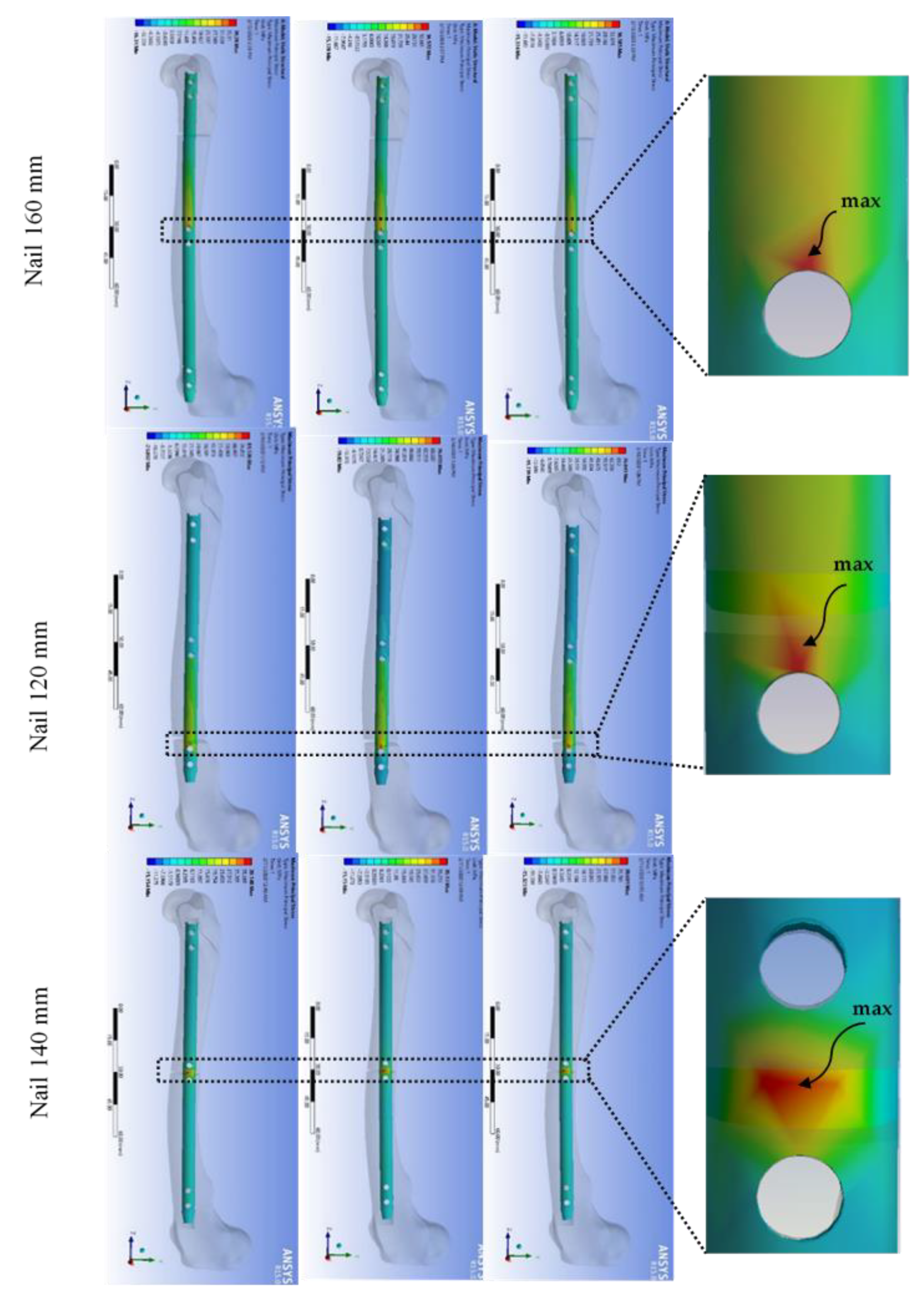
3.1. Numerical Modeling
3.2. Analysis of Variance
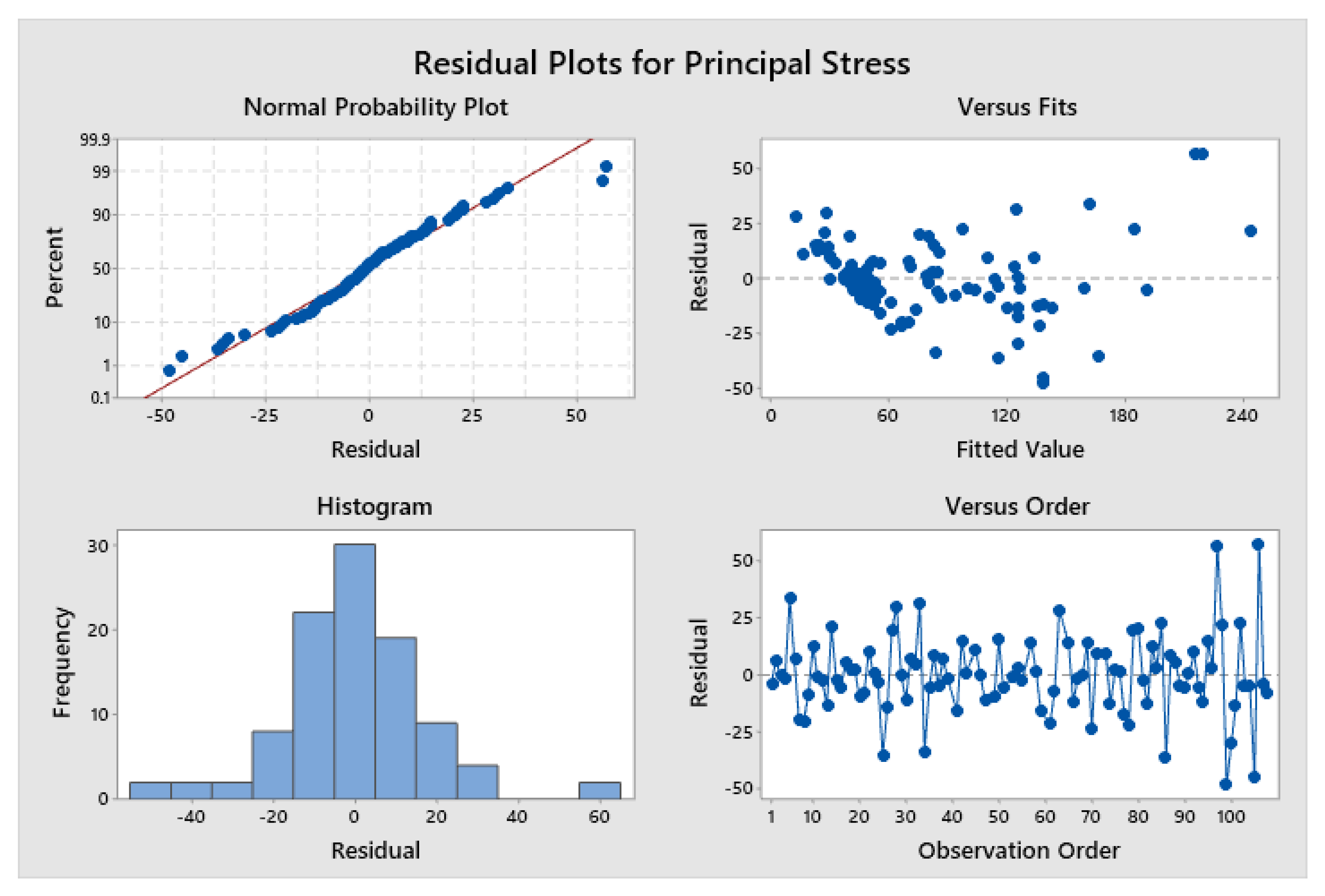
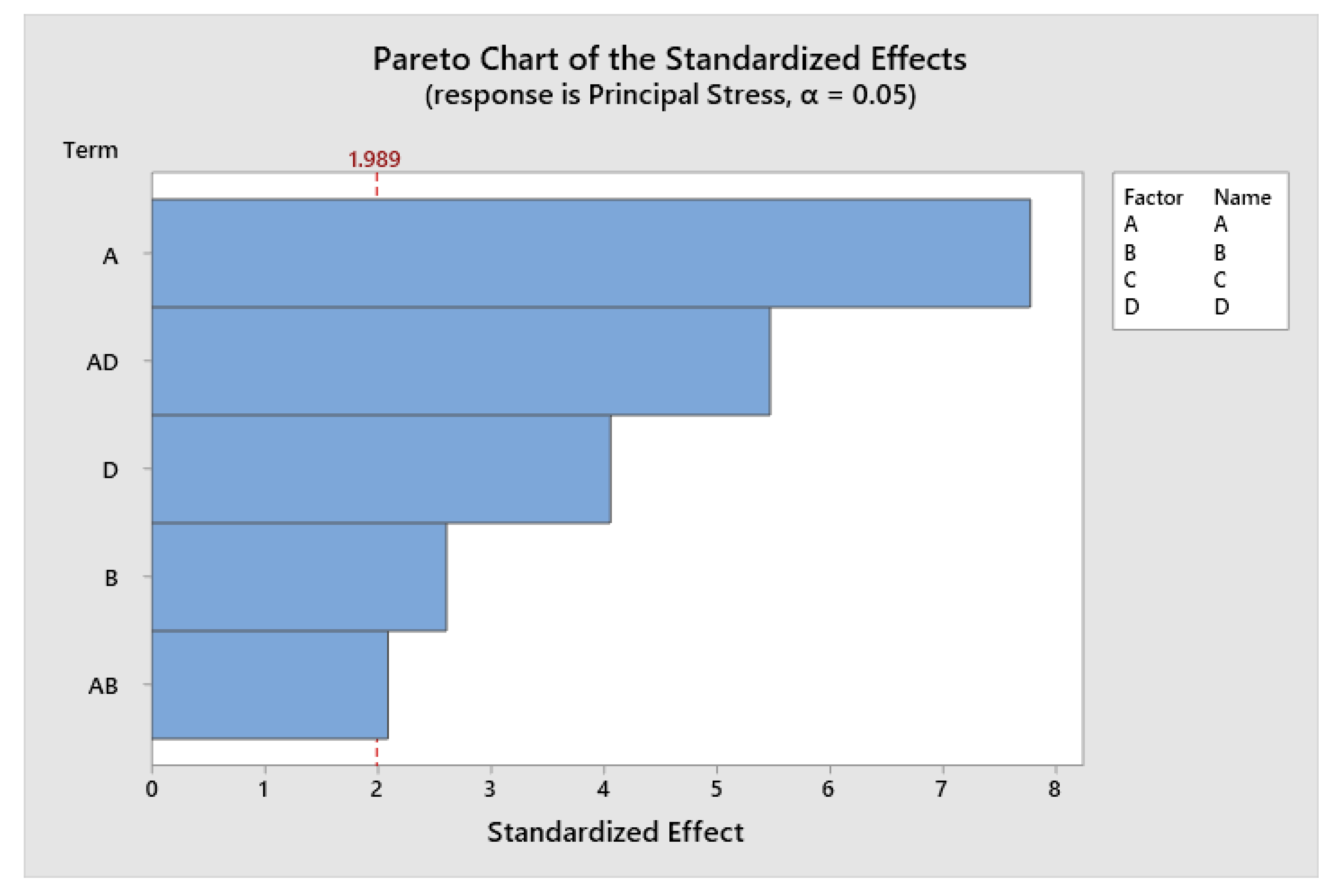
3.2.1. Two Locking Screws
3.2.2. Four Locking Screws
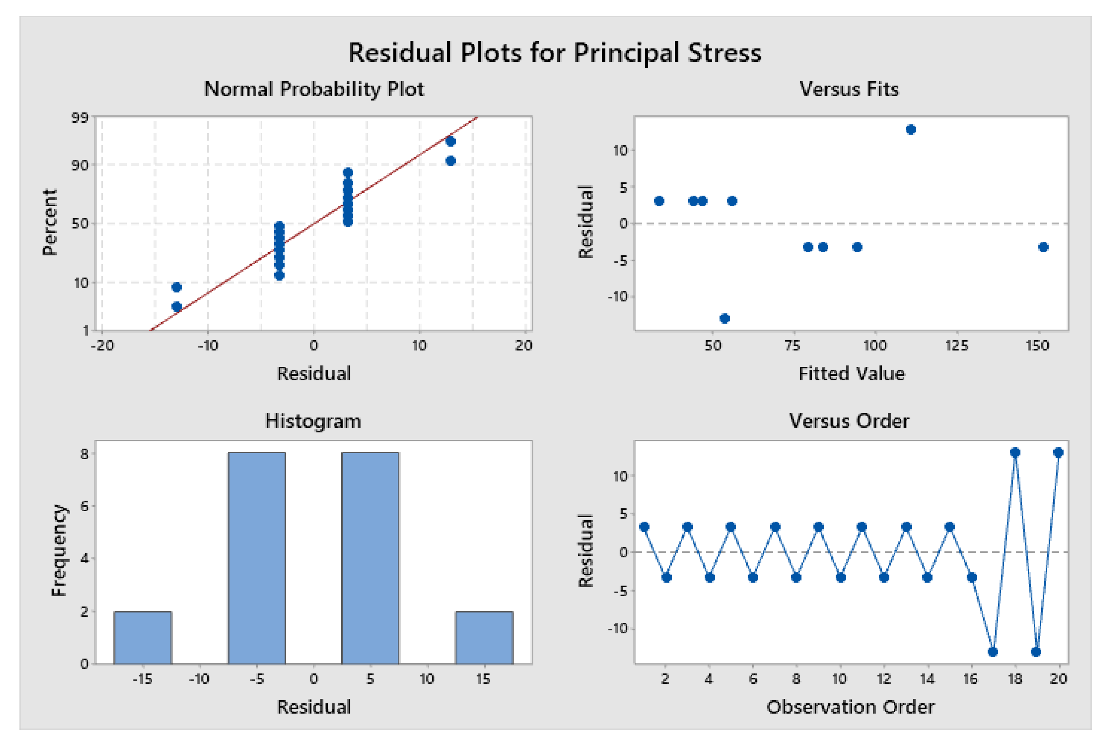
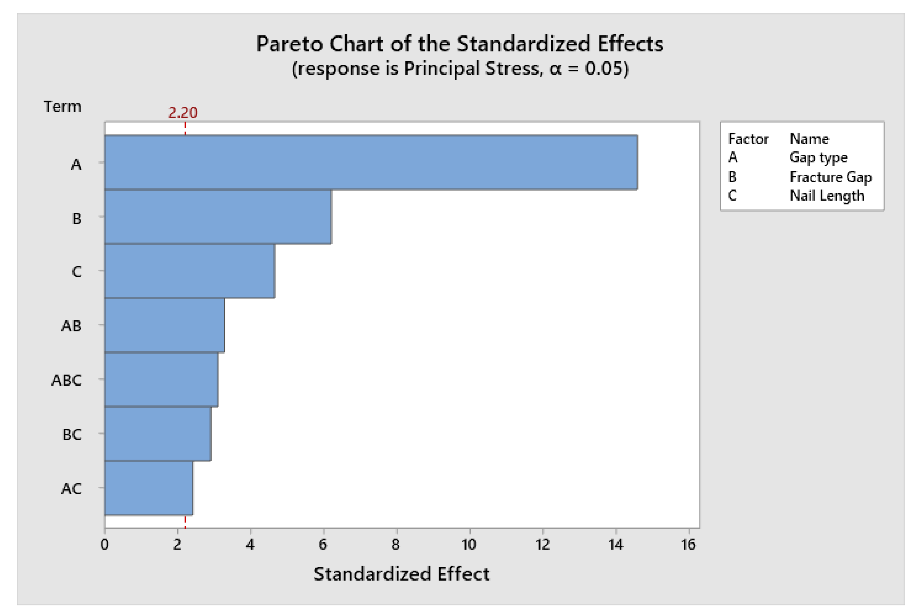
3.2.3. Six Locking Screws
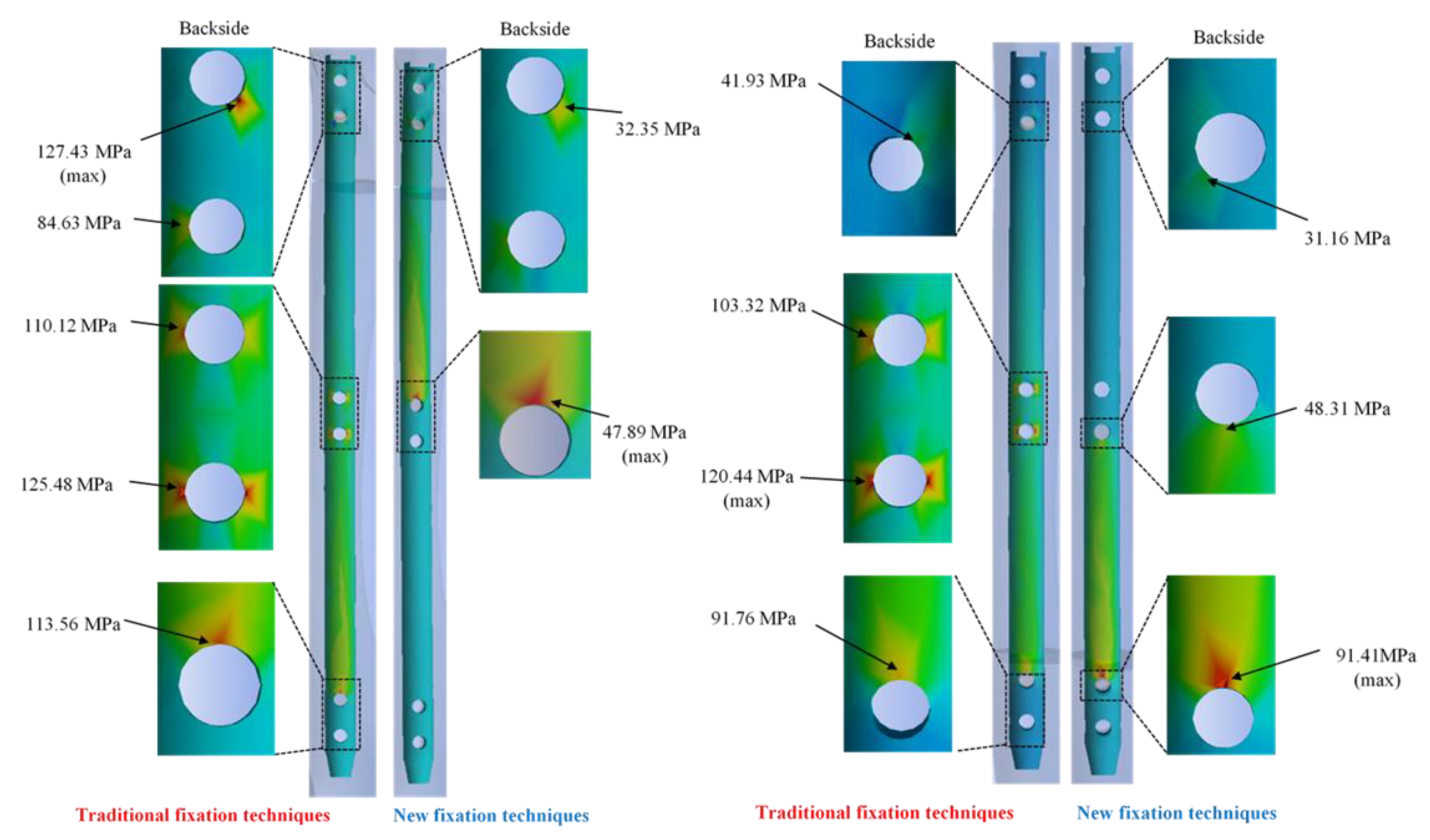
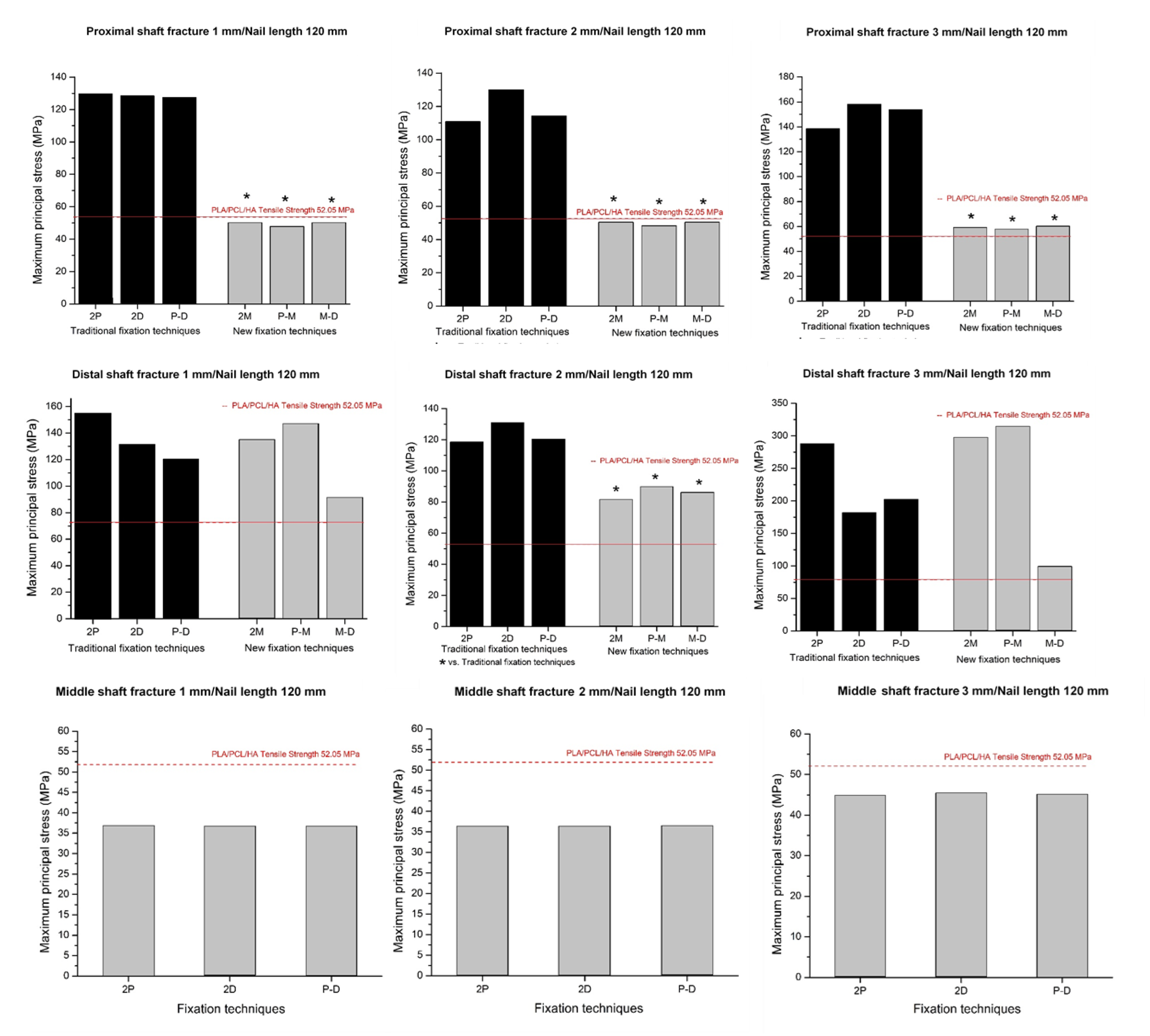
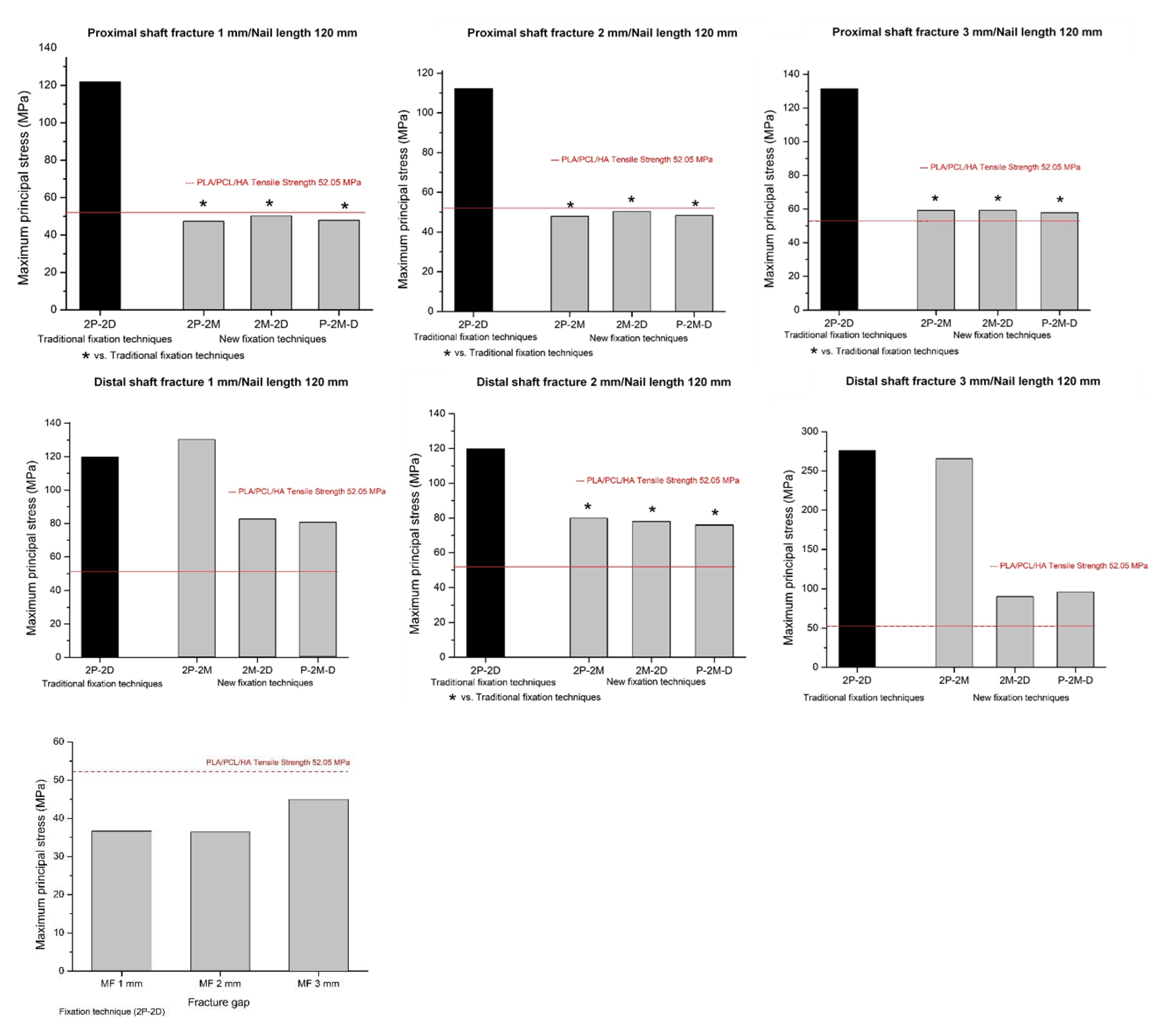
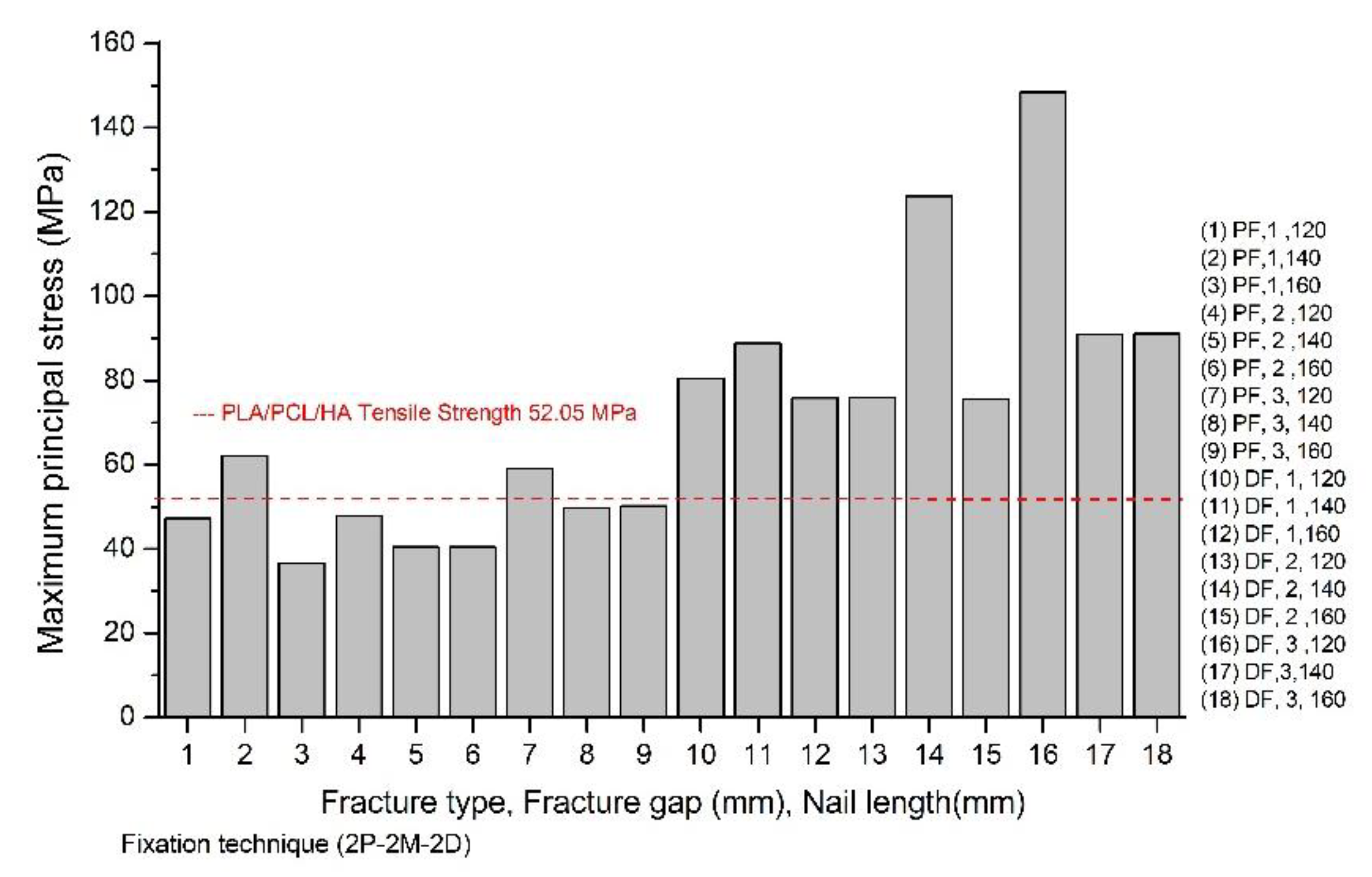
3.3. Maximum Principal Stresses of the Composite Interlocking Nailing System
4. Discussion
5. Conclusions
Author Contributions
Funding
Acknowledgments
Conflicts of Interest
References
- Dueland, R.; Berglund, L.; Vanderby, R., Jr.; Chao, E. Structural properties of interlocking nails, canine femora, and femur-interlocking nail constructs. Vet. Surg. 1996, 25, 386–396. [Google Scholar] [CrossRef] [PubMed]
- Bernarde, A.; Diop, A.; Maurel, N.; Viguier, E. An in vitro biomechanical study of bone plate and interlocking nail in a canine diaphyseal femoral fracture model. Vet. Surg. 2001, 30, 397–408. [Google Scholar] [CrossRef] [PubMed]
- Stiffler, K.S. Internal fracture fixation. Clin. Tech. Small Anim. Pract. 2004, 19, 105–113. [Google Scholar] [CrossRef] [PubMed]
- Déjardin, L.M.; Perry, K.L.; von Pfeil, D.J.; Guiot, L.P. Interlocking nails and minimally invasive osteosynthesis. Vet. Clin. Small Anim. Pract. 2020, 50, 67–100. [Google Scholar] [CrossRef] [PubMed]
- Déjardin, L.M.; Guiot, L.P.; von Pfeil, D.J. Interlocking nails and minimally invasive osteosynthesis. Vet. Clin. Small Anim. Pract. 2012, 42, 935–962. [Google Scholar] [CrossRef]
- Jacobs, J.J.; Gilbert, J.L.; Urban, R.M. Current concepts review-corrosion of metal orthopaedic implants. JBJS 1998, 80, 268–282. [Google Scholar] [CrossRef]
- Zhang, P.; Wang, X.; Lin, Z.; Lin, H.; Zhang, Z.; Li, W.; Yang, X.; Cui, J. Ti-based biomedical material modified with TiOx/TiNx duplex bioactivity film via Micro-Arc oxidation and nitrogen ion implantation. Nanomaterials 2017, 7, 343. [Google Scholar] [CrossRef] [Green Version]
- Räihä, J.; Axelson, P.; Rokkanen, P.; Törmälä, P. Intramedullary nailing of diaphyseal fractures with self-reinforced polylactide implants. J. Small Anim. Pract. 1993, 34, 337–344. [Google Scholar] [CrossRef]
- Van der Elst, M.; Dijkema, A.; Klein, C.; Patka, P.; Haarman, H.T.M. Tissue reaction on PLLA versus stainless steel interlocking nails for fracture fixation: An animal study. Biomaterials 1995, 16, 103–106. [Google Scholar] [CrossRef]
- Van der Elst, M.; Dijkema, A.; Klein, C.; Patka, P.; Haarman, H.T.M. Biodegradable PLA Versus Stainless Steel Intramedullary Devices for Fracture Fixation. A Comperative Histological Study. In Degradation Phenomena on Polymeric Biomaterials; Springer: Berlin, Germany, 1992; pp. 177–183. [Google Scholar]
- Van der Elst, M.; Klein, C.; de Blieck-Hogervorst, J.; Patka, P.; Haarman, H.T.M. Bone tissue response to biodegradable polymers used for intra medullary fracture fixation: A long-term in vivo study in sheep femora. Biomaterials 1999, 20, 121–128. [Google Scholar] [CrossRef]
- Gunatillake, P.A.; Adhikari, R. Biodegradable synthetic polymers for tissue engineering. Eur. Cells Mater. 2003, 5, 1–16. [Google Scholar] [CrossRef] [PubMed]
- Adeosun, S.O.; Lawal, G.I.; Gbenebor, O.P. Characteristics of biodegradable implants. J. Miner. Mater. Charact. Eng. 2014, 2, 88–106. [Google Scholar] [CrossRef] [Green Version]
- Hassanajili, S.; Karami-Pour, A.; Oryan, A.; Talaei-Khozani, T. Preparation and characterization of PLA/PCL/HA composite scaffolds using indirect 3D printing for bone tissue engineering. Mater. Sci. Eng. C 2019, 104, 109960. [Google Scholar] [CrossRef] [PubMed]
- Holländer, J.; Genina, N.; Jukarainen, H.; Khajeheian, M.; Rosling, A.; Mäkilä, E.; Sandler, N. Three-dimensional printed PCL-based implantable prototypes of medical devices for controlled drug delivery. J. Pharm. Sci. 2016, 105, 2665–2676. [Google Scholar] [CrossRef] [Green Version]
- Provaggi, E.; Capelli, C.; Rahmani, B.; Burriesci, G.; Kalaskar, D.M. 3D printing assisted finite element analysis for optimising the manufacturing parameters of a lumbar fusion cage. Mater. Des. 2019, 163, 107540. [Google Scholar] [CrossRef]
- Pitjamit, S.; Thunsiri, K.; Nakkiew, W.; Wongwichai, T.; Pothacharoen, P.; Wattanutchariya, W. The possibility of interlocking nail fabrication from FFF 3D printing PLA/PCL/HA composites coated by local silk fibroin for canine bone fracture treatment. Materials 2020, 13, 1564. [Google Scholar] [CrossRef] [Green Version]
- Cox, S.C.; Thornby, J.A.; Gibbons, G.J.; Williams, M.A.; Mallick, K.K. 3D printing of porous hydroxyapatite scaffolds intended for use in bone tissue engineering applications. Mater. Sci. Eng. C 2015, 47, 237–247. [Google Scholar] [CrossRef]
- Bakar, M.A.; Cheng, M.; Tang, S.; Yu, S.; Liao, K.; Tan, C.; Khor, K.; Cheang, P. Tensile properties, tension–tension fatigue and biological response of polyetheretherketone–hydroxyapatite composites for load-bearing orthopedic implants. Biomaterials 2003, 24, 2245–2250. [Google Scholar] [CrossRef]
- McLaughlin, R. Internal fixation: Intramedullary pins, cerclage wires, and interlocking nails. Vet. Clin. Small Anim. Pract. 1999, 29, 1097–1116. [Google Scholar] [CrossRef]
- von Pfeil, D.J.; Déjardin, L.M.; DeCamp, C.E.; Meyer, E.G.; Lansdowne, J.L.; Weerts, R.J.; Haut, R.C. In vitro biomechanical comparison of a plate-rod combination–construct and an interlocking nail–construct for experimentally induced gap fractures in canine tibiae. Am. J. Vet. Res. 2005, 66, 1536–1543. [Google Scholar] [CrossRef]
- Griza, S.; Zimmer, C.; Reguly, A.; Strohaecker, T. A case study of subsequential intramedullary nails failure. Eng. Fail. Anal. 2009, 16, 728–732. [Google Scholar] [CrossRef]
- Shih, K.-S.; Hsu, C.-C.; Hsu, T.-P. A biomechanical investigation of the effects of static fixation and dynamization after interlocking femoral nailing: A finite element study. J. Trauma Acute Care Surg. 2012, 72, E46–E53. [Google Scholar] [CrossRef]
- Liu, C.-c.; Xing, W.-z.; Zhang, Y.-x.; Pan, Z.-h.; Feng, W.-l. Three-dimensional finite element analysis and comparison of a new intramedullary fixation with interlocking intramedullary nail. Cell Biochem. Biophys. 2015, 71, 717–724. [Google Scholar] [CrossRef] [PubMed]
- Shih, K.-S.; Hsu, C.-C.; Hsu, T.-P.; Hou, S.-M.; Liaw, C.-K. Biomechanical analyses of static and dynamic fixation techniques of retrograde interlocking femoral nailing using nonlinear finite element methods. Comput. Methods Programs Biomed. 2014, 113, 456–464. [Google Scholar] [CrossRef] [PubMed]
- Shahar, R.; Banks-Sills, L.; Eliasy, R. Stress and strain distribution in the intact canine femur: Finite element analysis. Med. Eng. Phys. 2003, 25, 387–395. [Google Scholar] [CrossRef]
- Bureau, M.N.; Legoux, J.-G.; Denault, J. Implantable Biomimetic Prosthetic Bone. Google Patents US20090177282A1, 9 July 2009. [Google Scholar]
- Esmaeili, S.; Aghdam, H.A.; Motififard, M.; Saber-Samandari, S.; Montazeran, A.H.; Bigonah, M.; Sheikhbahaei, E.; Khandan, A. A porous polymeric–hydroxyapatite scaffold used for femur fractures treatment: Fabrication, analysis, and simulation. Eur. J. Orthop. Surg. Traumatol. 2020, 30, 123–131. [Google Scholar] [CrossRef] [PubMed]
- Innovative Animal Products. Available online: http://www.innovativeanimal.com/pdf/June%202009%20FINAL.pdf (accessed on 4 April 2020).
- Rodrigues, L.B.; Las Casas, E.B.; Lopes, D.S.; Folgado, J.; Fernandes, P.R.; Pires, E.A.; Alves, G.E.S.; Faleiros, R.R. A finite element model to simulate femoral fractures in calves: Testing different polymers for intramedullary interlocking nails. Vet. Surg. 2012, 41, 838–844. [Google Scholar] [CrossRef]
- Effects Plots for Analyze Factorial Design. Available online: https://support.minitab.com/en-us/minitab/18/help-and-how-to/modeling-statistics/doe/how-to/factorial/analyze-factorial-design/interpret-the-results/all-statistics-and-graphs/effects-plots/ (accessed on 6 May 2020).
- Cheung, G.; Zalzal, P.; Bhandari, M.; Spelt, J.; Papini, M. Finite element analysis of a femoral retrograde intramedullary nail subject to gait loading. Med. Eng. Phys. 2004, 26, 93–108. [Google Scholar] [CrossRef]
- Wu, C.; Tai, C. A biomechanical comparison of unlocked or locked reamed intramedullary nails in the treatment of mid-third simple transverse femoral shaft fractures. Chang Gung Med. J. 2006, 29, 275. [Google Scholar]
- Wu, C.-C.; Shih, C.-H. Biomechanical analysis of the mechanism of interlocking nail failure. Arch. Orthop. Trauma Surg. 1992, 111, 268–272. [Google Scholar] [CrossRef]
- Bhat, A.K.; Rao, S.K.; Bhaskaranand, K. Mechanical failure in intramedullary interlocking nails. J. Orthop. Surg. 2006, 14, 138–141. [Google Scholar] [CrossRef]
- Bayoglu, R.; Okyar, A.F. Implementation of boundary conditions in modeling the femur is critical for the evaluation of distal intramedullary nailing. Med. Eng. Phys. 2015, 37, 1053–1060. [Google Scholar] [CrossRef]
- Penzkofer, R.; Maier, M.; Nolte, A.; von Oldenburg, G.; Püschel, K.; Bühren, V.; Augat, P. Influence of intramedullary nail diameter and locking mode on the stability of tibial shaft fracture fixation. Arch. Orthop. Trauma Surg. 2009, 129, 525. [Google Scholar] [CrossRef]
- Chen, A.L.; Joseph, T.N.; Wolinksy, P.R.; Tejwani, N.C.; Kummer, F.J.; Egol, K.A.; Koval, K.J. Fixation stability of comminuted humeral shaft fractures: Locked intramedullary nailing versus plate fixation. J. Trauma Acute Care Surg. 2002, 53, 733–737. [Google Scholar] [CrossRef]
- Den Buijs, J.O.; Dragomir-Daescu, D. Validated finite element models of the proximal femur using two-dimensional projected geometry and bone density. Comput. Methods Programs Biomed. 2011, 104, 168–174. [Google Scholar] [CrossRef] [Green Version]
- Rodriguez-Merchan, E.C.; Forriol, F. Nonunion: General principles and experimental data. Clin. Orthop. Relat. Res. 2004, 419, 4–12. [Google Scholar] [CrossRef]
- Wu, C.-C. Retrograde dynamic locked nailing for femoral supracondylar nonunions after plating. J. Trauma Acute Care Surg. 2009, 66, 195–199. [Google Scholar] [CrossRef] [PubMed]
- Basumallick, M.; Bandopadhyay, A. Effect of dynamization in open interlocking nailing of femoral fractures. A prospective randomized comparative study of 50 cases with a 2-year follow-up. Acta Orthop. Belg. 2002, 68, 42–48. [Google Scholar] [PubMed]
- Wu, C.-C.; Chen, W.-J. Healing of 56 segmental femoral shaft fractures after locked nailing: Poor results of dynamization. Acta Orthop. Scand. 1997, 68, 537–540. [Google Scholar] [CrossRef] [PubMed] [Green Version]
- Bergmann, G.; Deuretzbacher, G.; Heller, M.; Graichen, F.; Rohlmann, A.; Strauss, J.; Duda, G. Hip contact forces and gait patterns from routine activities. J. Biomech. 2001, 34, 859–871. [Google Scholar] [CrossRef]
- Wu, C.; Shih, C.-H. Treatment for nonunion of the shaft of the humerus: Comparison of plates and Seidel interlocking nails. Can. J. Surgery. J. Can. Chir. 1992, 35, 661–665. [Google Scholar]
- Bucholz, R.W.; Ross, S.E.; Lawrence, K. Fatigue fracture of the interlocking nail in the treatment of fractures of the distal part of the femoral shaft. J. Bone Jt. Surg. Am. Vol. 1987, 69, 1391–1399. [Google Scholar]
- Im, G.-I.; Shin, S.-R. Treatment of femoral shaft fractures with a titanium intramedullary nail. Clin. Orthop. Relat. Res. 2002, 401, 223–229. [Google Scholar] [CrossRef] [PubMed]
- Balani, K.; Verma, V.; Agarwal, A.; Narayan, R. Physical, thermal, and mechanical properties of polymers. Mater. Res. Innov. 2014, 42, 54–67. [Google Scholar]
- Factors Affecting the Tensile Strength of Materials. Available online: https://medium.com/@prestogroup/factors-affecting-the-tensile-strength-of-materials-bf1548f4e6bd (accessed on 6 May 2020).
- Molar Volume and Density of Polymers. Available online: https://polymerdatabase.com/polymer%20physics/MolarVolume.html?fbclid=IwAR0VYGbdm5Av9G9hBttTGz0BM0_-yE9JGUkREG88ALIeAtbVp7b_PXRyfn4 (accessed on 6 May 2020).
- Navarro-Baena, I.; Sessini, V.; Dominici, F.; Torre, L.; Kenny, J.M.; Peponi, L. Design of biodegradable blends based on PLA and PCL: From morphological, thermal and mechanical studies to shape memory behavior. Polym. Degrad. Stab. 2016, 132, 97–108. [Google Scholar] [CrossRef]
- Orthopedic Follow-Up Evaluations: Identifying Complications. Available online: https://todaysveterinarypractice.com/wp-content/uploads/sites/4/2016/06/T1409C09.pdf (accessed on 5 May 2020).
- DeCamp, C.E. Brinker, Piermattei and Flo’s Handbook of Small Animal Orthopedics and Fracture Repair, 5th ed.; Elsevier Health Sciences: Michigan, MI, USA, 2015. [Google Scholar]
- Dubinenko, G.E.; Zinoviev, A.L.; Bolbasov, E.N.; Novikov, V.T.; Tverdokhlebov, S.I. Preparation of Poly (L-lactic acid)/Hydroxyapatite composite scaffolds by fused deposit modeling 3D printing. Mater. Today Proc. 2020, 22, 228–234. [Google Scholar] [CrossRef]
- Patralekh, M.K.; Lal, H. 3D printing in orthopedic trauma. In Precision Medicine for Investigators, Practitioners and Providers; Elsevier: Amsterdam, The Netherlands, 2020; pp. 483–492. [Google Scholar]
- Allen, B.; Moore, C.; Seyler, T.; Gall, K. Modulating antibiotic release from reservoirs in 3D-printed orthopedic devices to treat periprosthetic joint infection. J. Orthop. Res. 2020. [Google Scholar] [CrossRef]
- Ahirwar, H.; Zhou, Y.; Mahapatra, C.; Ramakrishna, S.; Kumar, P.; Nanda, H.S. Materials for orthopedic bioimplants: Modulating degradation and surface modification using integrated nanomaterials. Coatings 2020, 10, 264. [Google Scholar] [CrossRef] [Green Version]


| Material Properties | Cortical Bone | PLA/PCL/15HA |
|---|---|---|
| Compressive strength (MPa) | 193 | 82.72 |
| Tensile strength (MPa) | 150 | 52.02 |
| Young’s modulus (GPa) | 15 | 1.06 |
| Poisson’s ratio | 0.3 | 0.34 |
| Density (g/cm3) | 2.0 | 2.0 |
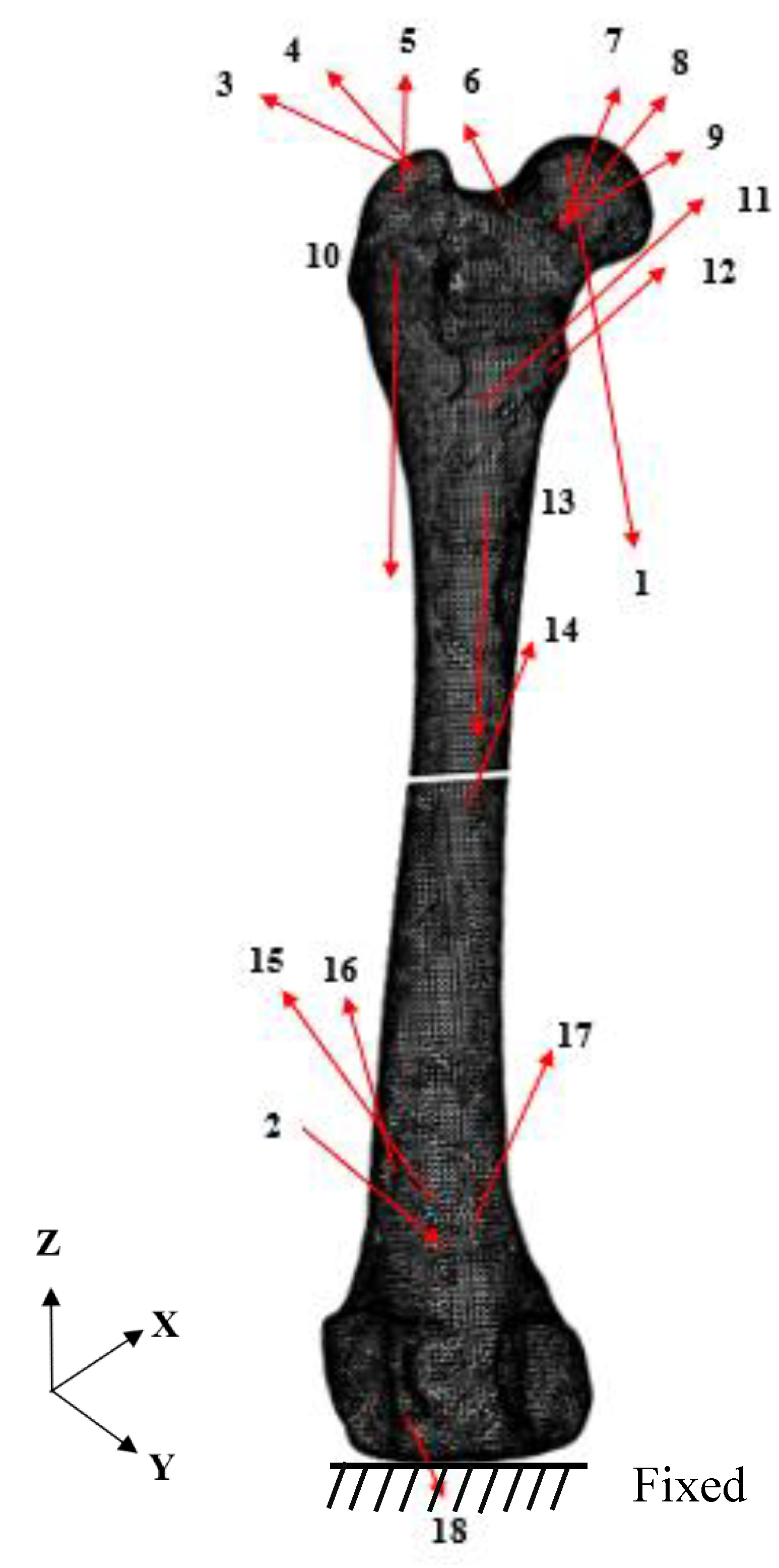
| Number | Force | Fx (N) | Fy (N) | Fz (N) |
|---|---|---|---|---|
| 1 | Hip-joint reaction force | −10.10 | 52.42 | −232.74 |
| 2 | Patellofemoral reaction force | −9.18 | 81.46 | 20.03 |
| 3 | Medial gluteal | 7.25 | −36.92 | 15.29 |
| 4 | Piriformis | 4.99 | −5.65 | 3.37 |
| 5 | Superficial gluteal | 1.01 | −9.02 | 1.48 |
| 6 | Articularis coxae | −0.05 | −0.13 | 0.29 |
| 7 | Gemelli | 1.52 | 2.05 | 2.46 |
| 8 | External obturator | 2.11 | 2.85 | 3.41 |
| 9 | Internal obturator | 0.38 | 0.15 | 0.61 |
| 10 | Lateral and intermediate vastus | 4.49 | −1.55 | −38.30 |
| 11 | Iliopsoas | −0.17 | −1.25 | 0.88 |
| 12 | Quadratus femoris | 1.12 | 3.44 | 3.64 |
| 13 | Medial vastus | 0.38 | −3.46 | −40.52 |
| 14 | Adductor magnus and brevis | 5.91 | 2.55 | 9.17 |
| 15 | Pectineus | 0.11 | −0.05 | 0.44 |
| 16 | Cranial tensor fascia latae | −0.17 | −2.43 | 8.44 |
| 17 | Semimembranosus | 0.09 | 7.10 | 19.64 |
| 18 | Long digital extensor | 3.53 | 6.78 | −10.40 |
| Factors | Levels | Unit | |||||
|---|---|---|---|---|---|---|---|
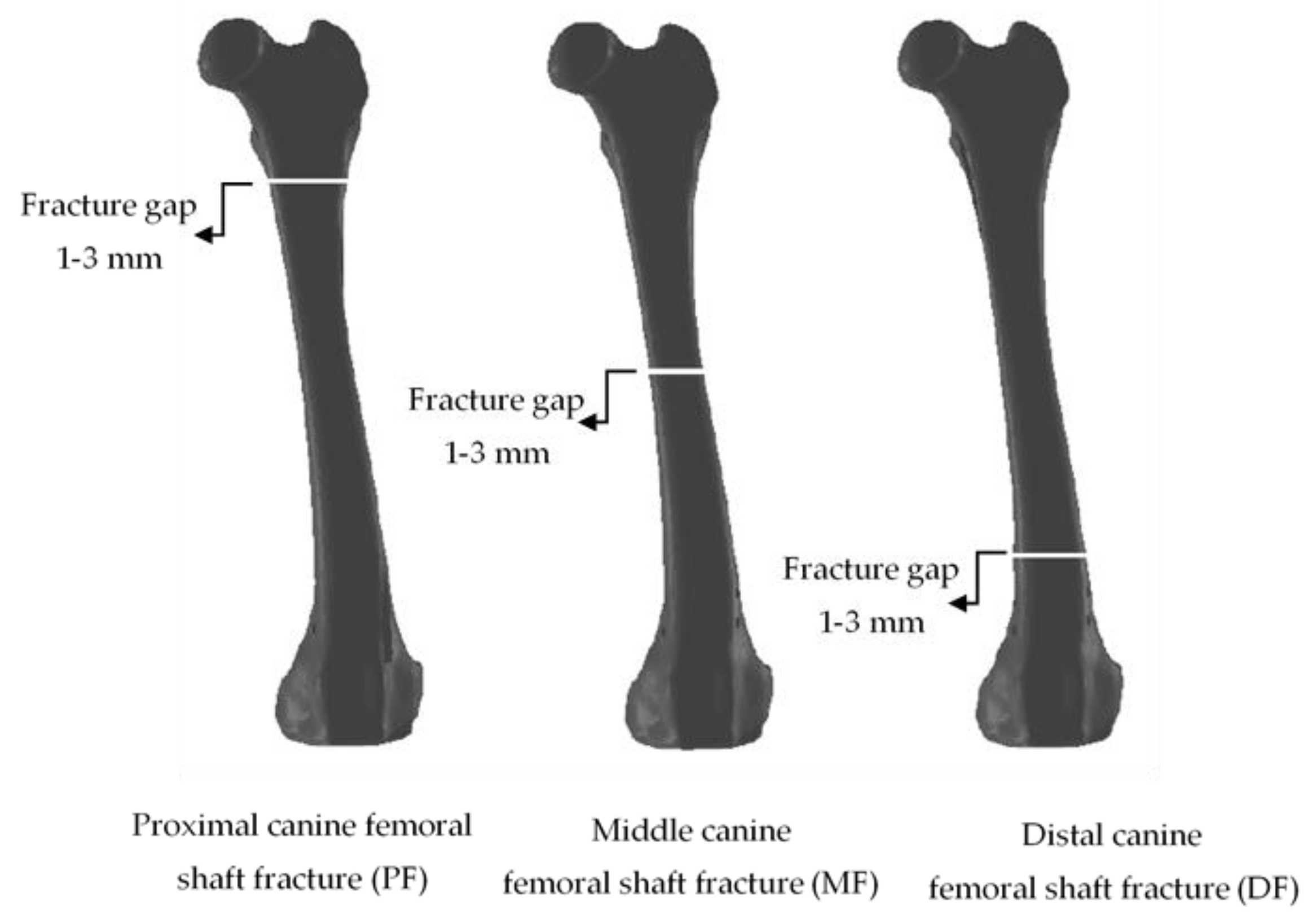
| Gap Type (A) | Proximal | Middle | Distal | Type | |||
| Fracture gap (B) | 1 | 2 | 3 | mm | |||
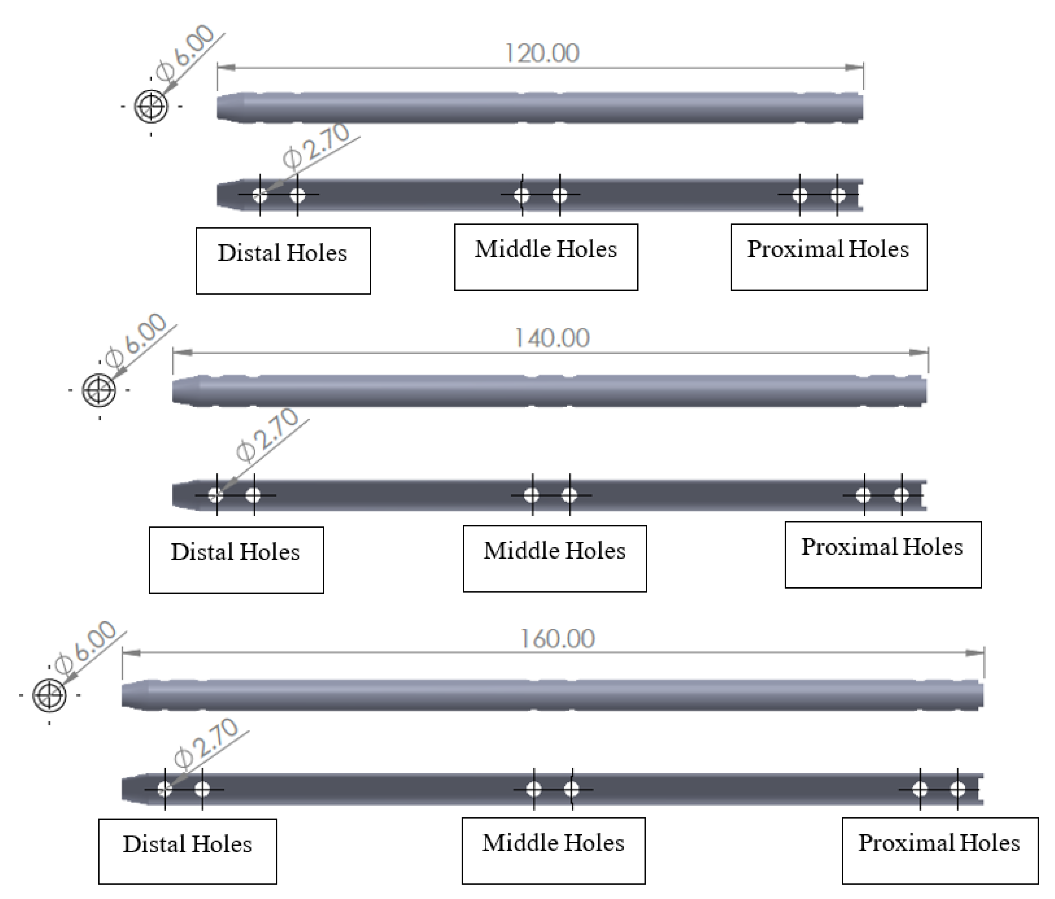
| Nail length (C) | 120 | 140 | 160 | mm | |||
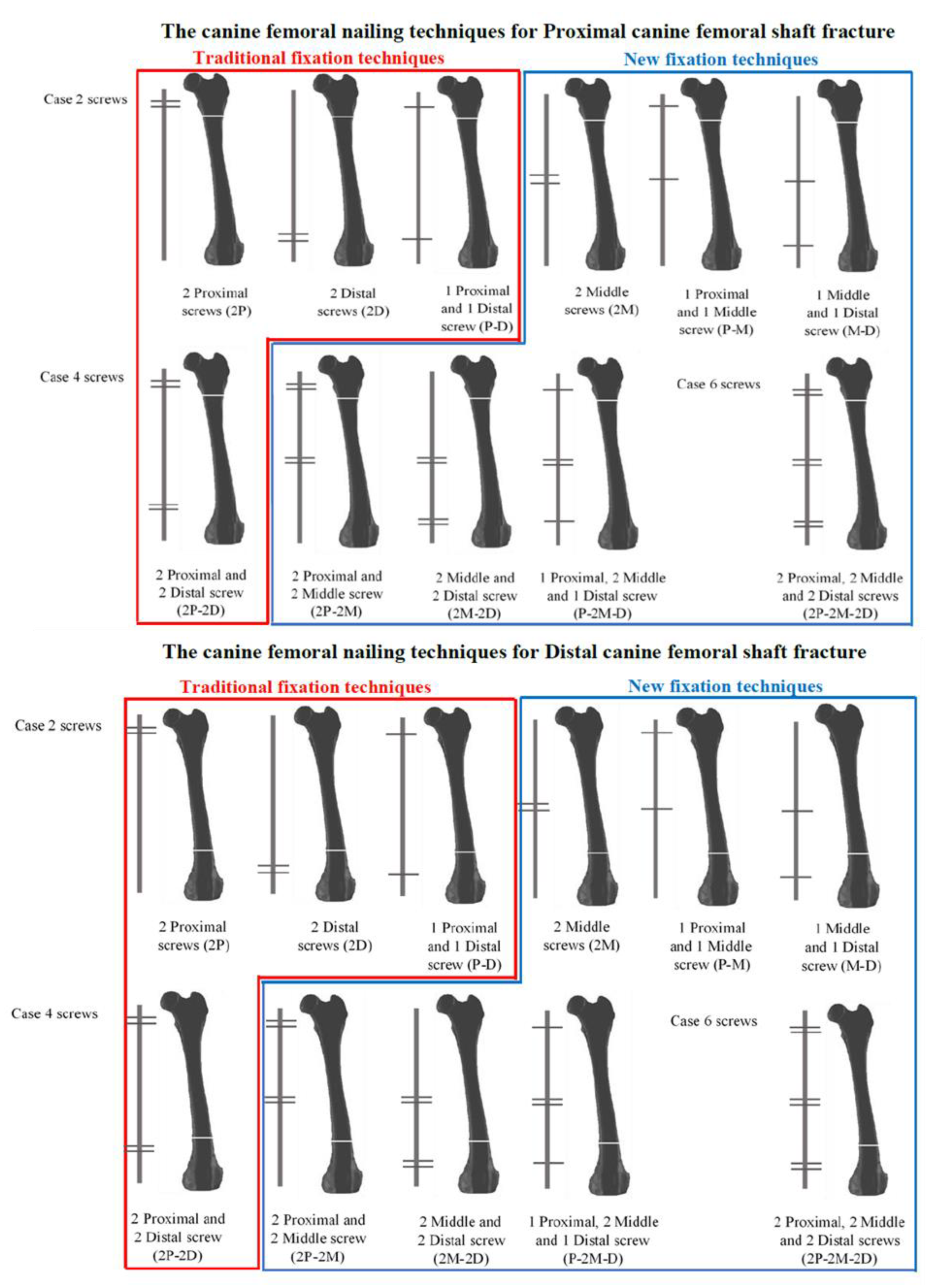
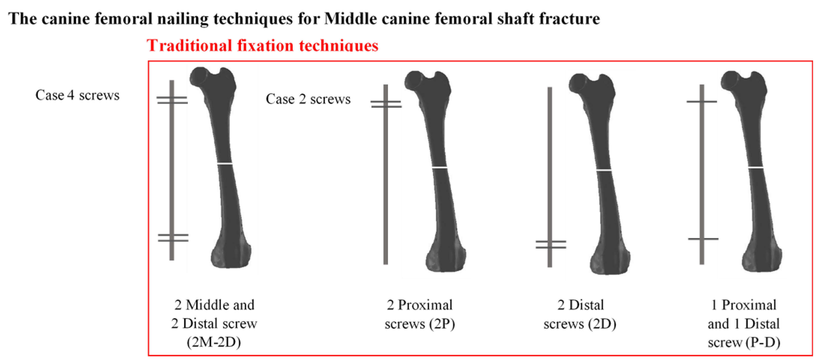
| Fixation techniques (D) | 2P | 2D | 2M | P–D | P–M | M–D | type |
| Factors | Levels | Unit | |||
|---|---|---|---|---|---|
| Gap Type (A) | Proximal | Middle | Distal | Type | |
| Fracture gap (B) | 1 | 2 | 3 | mm | |
| Nail length (C) | 120 | 140 | 160 | mm | |
| Fixation techniques (D) | 2P–2D | 2P–2M | 2M–2D | P–2M–D | type |
| Factors | Levels | Unit | ||
|---|---|---|---|---|
| Gap Type (A) | Proximal | Distal | Type | |
| Fracture gap (B) | 1 | 2 | 3 | mm |
| Nail length (C) | 120 | 140 | 160 | mm |
| Fixation techniques * | 2P–2M–2D | Type | ||
| Elements | Nodes | |
|---|---|---|
| Two locking screws | ||
| 120 mm interlocking nail | 140,762 | 228,472 |
| 140 mm interlocking nail | 146,210 | 237,583 |
| 160 mm interlocking nail | 150,939 | 245,140 |
| Four locking screws | ||
| 120 mm interlocking nail | 143,179 | 232,836 |
| 140 mm interlocking nail | 148,984 | 242,533 |
| 160 mm interlocking nail | 152,973 | 248,812 |
| Six locking screws | ||
| 120 mm interlocking nail | 144,881 | 235,920 |
| 140 mm interlocking nail | 151,282 | 246,595 |
| 160 mm interlocking nail | 154,759 | 252,052 |
| Condition | A | B | C | D | Principal Stress | Condition | A | B | C | D | Principal Stress |
| 1 | Proximal | 1 | 120 | 2P | 129.75 | 38 | Proximal | 3 | 120 | 2D | 158.2 |
| 2 | Proximal | 1 | 120 | 2D | 128.35 | 39 | Proximal | 3 | 120 | 2M | 59.3 |
| 3 | Proximal | 1 | 120 | 2M | 50.24 | 40 | Proximal | 3 | 120 | P–D | 153.86 |
| 4 | Proximal | 1 | 120 | P–D | 127.43 | 41 | Proximal | 3 | 120 | P–M | 57.89 |
| 5 | Proximal | 1 | 120 | P–M | 47.89 | 42 | Proximal | 3 | 120 | M–D | 60.23 |
| 6 | Proximal | 1 | 120 | M–D | 50.24 | 43 | Proximal | 3 | 140 | 2P | 164.12 |
| 7 | Proximal | 1 | 140 | 2P | 209.63 | 44 | Proximal | 3 | 140 | 2D | 163.07 |
| 8 | Proximal | 1 | 140 | 2D | 145.02 | 45 | Proximal | 3 | 140 | 2M | 58.17 |
| 9 | Proximal | 1 | 140 | 2M | 50.07 | 46 | Proximal | 3 | 140 | P–D | 141.89 |
| 10 | Proximal | 1 | 140 | P–D | 112.6 | 47 | Proximal | 3 | 140 | P–M | 53.67 |
| 11 | Proximal | 1 | 140 | P–M | 46.13 | 48 | Proximal | 3 | 140 | M–D | 58.2 |
| 12 | Proximal | 1 | 140 | M–D | 50.11 | 49 | Proximal | 3 | 160 | 2P | 171.5 |
| 13 | Proximal | 1 | 160 | 2P | 198.89 | 50 | Proximal | 3 | 160 | 2D | 168.02 |
| 14 | Proximal | 1 | 160 | 2D | 120.17 | 51 | Proximal | 3 | 160 | 2M | 49.68 |
| 15 | Proximal | 1 | 160 | 2M | 44.44 | 52 | Proximal | 3 | 160 | P–D | 211 |
| 16 | Proximal | 1 | 160 | P–D | 84.52 | 53 | Proximal | 3 | 160 | P–M | 92.14 |
| 17 | Proximal | 1 | 160 | P–M | 39.28 | 54 | Proximal | 3 | 160 | M–D | 49.92 |
| 18 | Proximal | 1 | 160 | M–D | 44.43 | 55 | Middle | 1 | 120 | 2P | 36.7 |
| 19 | Proximal | 2 | 120 | 2P | 110.87 | 56 | Middle | 1 | 120 | 2D | 36.73 |
| 20 | Proximal | 2 | 120 | 2D | 129.73 | 57 | Middle | 1 | 120 | 2M | * |
| 21 | Proximal | 2 | 120 | 2M | 50.37 | 58 | Middle | 1 | 120 | P–D | 36.72 |
| 22 | Proximal | 2 | 120 | P–D | 114.36 | 59 | Middle | 1 | 120 | P–M | * |
| 23 | Proximal | 2 | 120 | P–M | 48.3 | 60 | Middle | 1 | 120 | M–D | * |
| 24 | Proximal | 2 | 120 | M–D | 50.37 | 61 | Middle | 1 | 140 | 2P | 39.13 |
| 25 | Proximal | 2 | 140 | 2P | 137.89 | 62 | Middle | 1 | 140 | 2D | 39.96 |
| 26 | Proximal | 2 | 140 | 2D | 130.24 | 63 | Middle | 1 | 140 | 2M | * |
| 27 | Proximal | 2 | 140 | 2M | 46.34 | 64 | Middle | 1 | 140 | P–D | 39.69 |
| 28 | Proximal | 2 | 140 | P–D | 105.97 | 65 | Middle | 1 | 140 | P–M | * |
| 29 | Proximal | 2 | 140 | P–M | 43.28 | 66 | Middle | 1 | 140 | M–D | * |
| 30 | Proximal | 2 | 140 | M–D | 46.35 | 67 | Middle | 1 | 160 | 2P | 27.24 |
| 31 | Proximal | 2 | 160 | 2P | 152.42 | 68 | Middle | 1 | 160 | 2D | 28.2 |
| 32 | Proximal | 2 | 160 | 2D | 136.94 | 69 | Middle | 1 | 160 | 2M | * |
| 33 | Proximal | 2 | 160 | 2M | 46.94 | 70 | Middle | 1 | 160 | P–D | 27.93 |
| 34 | Proximal | 2 | 160 | P–D | 118 | 71 | Middle | 1 | 160 | P–M | * |
| 35 | Proximal | 2 | 160 | P–M | 46.01 | 72 | Middle | 1 | 160 | M–D | * |
| 36 | Proximal | 2 | 160 | M–D | 46.95 | 73 | Middle | 2 | 120 | 2P | 36.34 |
| 37 | Proximal | 3 | 120 | 2P | 138.4 | 74 | Middle | 2 | 120 | 2D | 36.37 |
| Condition | A | B | C | D | Principal Stress | Condition | A | B | C | D | Principal Stress |
| 81 | Middle | 2 | 140 | 2M | * | 118 | Distal | 1 | 140 | P-D | 132.12 |
| 82 | Middle | 2 | 140 | P-D | 48.63 | 119 | Distal | 1 | 140 | P-M | 132.19 |
| 83 | Middle | 2 | 140 | P-M | * | 120 | Distal | 1 | 140 | M-D | 104.47 |
| 84 | Middle | 2 | 140 | M-D | * | 121 | Distal | 1 | 160 | 2P | 126.23 |
| 85 | Middle | 2 | 160 | 2P | 43.41 | 122 | Distal | 1 | 160 | 2D | 131.05 |
| 86 | Middle | 2 | 160 | 2D | 45.37 | 123 | Distal | 1 | 160 | 2M | 162.22 |
| 87 | Middle | 2 | 160 | 2M | * | 124 | Distal | 1 | 160 | P-D | 86.37 |
| 88 | Middle | 2 | 160 | P-D | 44.99 | 125 | Distal | 1 | 160 | P-M | 142.48 |
| 89 | Middle | 2 | 160 | P-M | * | 126 | Distal | 1 | 160 | M-D | 98.69 |
| 90 | Middle | 2 | 160 | M-D | * | 127 | Distal | 2 | 120 | 2P | 118.59 |
| 91 | Middle | 3 | 120 | 2P | 44.84 | 128 | Distal | 2 | 120 | 2D | 131.05 |
| 92 | Middle | 3 | 120 | 2D | 45.44 | 129 | Distal | 2 | 120 | 2M | 81.53 |
| 93 | Middle | 3 | 120 | 2M | * | 130 | Distal | 2 | 120 | P-D | 120.33 |
| 94 | Middle | 3 | 120 | P-D | 45.13 | 131 | Distal | 2 | 120 | P-M | 89.82 |
| 95 | Middle | 3 | 120 | P-M | * | 132 | Distal | 2 | 120 | M-D | 86.22 |
| 96 | Middle | 3 | 120 | M-D | * | 133 | Distal | 2 | 140 | 2P | 186.02 |
| 97 | Middle | 3 | 140 | 2P | 48.57 | 134 | Distal | 2 | 140 | 2D | 159.14 |
| 98 | Middle | 3 | 140 | 2D | 49.02 | 135 | Distal | 2 | 140 | 2M | 190.35 |
| 99 | Middle | 3 | 140 | 2M | * | 136 | Distal | 2 | 140 | P-D | 158.46 |
| 100 | Middle | 3 | 140 | P-D | 50.85 | 137 | Distal | 2 | 140 | P-M | 190.02 |
| 101 | Middle | 3 | 140 | P-M | * | 138 | Distal | 2 | 140 | M-D | 144.26 |
| 102 | Middle | 3 | 140 | M-D | * | 139 | Distal | 2 | 160 | 2P | 134.75 |
| 103 | Middle | 3 | 160 | 2P | 39.62 | 140 | Distal | 2 | 160 | 2D | 127.98 |
| 104 | Middle | 3 | 160 | 2D | 45.51 | 141 | Distal | 2 | 160 | 2M | 176.06 |
| 105 | Middle | 3 | 160 | 2M | * | 142 | Distal | 2 | 160 | P-D | 92.66 |
| 106 | Middle | 3 | 160 | P-D | 42.86 | 143 | Distal | 2 | 160 | P-M | 154.41 |
| 107 | Middle | 3 | 160 | P-M | * | 144 | Distal | 2 | 160 | M-D | 98.84 |
| 108 | Middle | 3 | 160 | M-D | * | 145 | Distal | 3 | 120 | 2P | 287.54 |
| 109 | Distal | 1 | 120 | 2P | 154.55 | 146 | Distal | 3 | 120 | 2D | 182.01 |
| 110 | Distal | 1 | 120 | 2D | 131.01 | 147 | Distal | 3 | 120 | 2M | 297.06 |
| 111 | Distal | 1 | 120 | 2M | 134.98 | 148 | Distal | 3 | 120 | P-D | 202.58 |
| 112 | Distal | 1 | 120 | P-D | 120.44 | 149 | Distal | 3 | 120 | P-M | 314.64 |
| 113 | Distal | 1 | 120 | P-M | 146.98 | 150 | Distal | 3 | 120 | M-D | 99.25 |
| 114 | Distal | 1 | 120 | M-D | 91.41 | 151 | Distal | 3 | 140 | 2P | 229.15 |
| 115 | Distal | 1 | 140 | 2P | 122.8 | 152 | Distal | 3 | 140 | 2D | 137.82 |
| 116 | Distal | 1 | 140 | 2D | 104.52 | 153 | Distal | 3 | 140 | 2M | 228.98 |
| 117 | Distal | 1 | 140 | 2M | 129.35 | 154 | Distal | 3 | 140 | P-D | 125.09 |
| 155 | Distal | 3 | 140 | P-M | 218.22 | ||||||
| 156 | Distal | 3 | 140 | M-D | 104.35 | ||||||
| 157 | Distal | 3 | 160 | 2P | 283.41 | ||||||
| 158 | Distal | 3 | 160 | 2D | 164.47 | ||||||
| 159 | Distal | 3 | 160 | 2M | 249.58 | ||||||
| 160 | Distal | 3 | 160 | P-D | 128.83 | ||||||
| 161 | Distal | 3 | 160 | P-M | 315.93 | ||||||
| 162 | Distal | 3 | 160 | M-D | 112.42 |
| Source | DF | Adj. SS | Adj. MS | F-Value | P-Value |
|---|---|---|---|---|---|
| Model | 23 | 505,293 | 21,969.3 | 26.18 | 0.000 |
| Linear | 9 | 230,383 | 25,598.1 | 30.51 | 0.000 |
| A | 2 | 151,544 | 75,772.0 | 90.30 | 0.000 |
| B | 2 | 34,878 | 17,439.0 | 20.78 | 0.000 |
| D | 5 | 23,384 | 4676.7 | 5.57 | 0.000 |
| 2-Way Interactions | 14 | 127,635 | 9116.8 | 10.86 | 0.000 |
| A*B | 4 | 24,258 | 6064.4 | 7.23 | 0.000 |
| A*D | 10 | 100,187 | 10,018.7 | 11.94 | 0.000 |
| Error | 115 | 96,498 | 839.1 | ||
| Total | 138 | 601,791 |
| Condition | A | B | C | D | Principal Stress | Condition | A | B | C | D | Principal Stress | Condition | A | B | C | D | Principal Stress |
| 1 | Proximal | 1 | 120 | 2P-2D | 121.95 | 38 | Middle | 1 | 120 | 2P-2M | * | 75 | Distal | 1 | 120 | 2M-2D | 82.77 |
| 2 | Proximal | 1 | 120 | 2P-2M | 47.31 | 39 | Middle | 1 | 120 | 2M-2D | * | 76 | Distal | 1 | 120 | P-2M-D | 80.56 |
| 3 | Proximal | 1 | 120 | 2M-2D | 50.22 | 40 | Middle | 1 | 120 | P-2M-D | * | 77 | Distal | 1 | 140 | 2P-2D | 107.99 |
| 4 | Proximal | 1 | 120 | P-2M-D | 47.93 | 41 | Middle | 1 | 140 | 2P-2D | 39.14 | 78 | Distal | 1 | 140 | 2P-2M | 115 |
| 5 | Proximal | 1 | 140 | 2P-2D | 195.93 | 42 | Middle | 1 | 140 | 2P-2M | * | 79 | Distal | 1 | 140 | 2M-2D | 98.92 |
| 6 | Proximal | 1 | 140 | 2P-2M | 62.29 | 43 | Middle | 1 | 140 | 2M-2D | * | 80 | Distal | 1 | 140 | P-2M-D | 95.63 |
| 7 | Proximal | 1 | 140 | 2M-2D | 50.07 | 44 | Middle | 1 | 140 | P-2M-D | * | 81 | Distal | 1 | 160 | 2P-2D | 77.88 |
| 8 | Proximal | 1 | 140 | P-2M-D | 46.17 | 45 | Middle | 1 | 160 | 2P-2D | 27.25 | 82 | Distal | 1 | 160 | 2P-2M | 122.95 |
| 9 | Proximal | 1 | 160 | 2P-2D | 77.32 | 46 | Middle | 1 | 160 | 2P-2M | * | 83 | Distal | 1 | 160 | 2M-2D | 97.98 |
| 10 | Proximal | 1 | 160 | 2P-2M | 36.57 | 47 | Middle | 1 | 160 | 2M-2D | * | 84 | Distal | 1 | 160 | P-2M-D | 84.28 |
| 11 | Proximal | 1 | 160 | 2M-2D | 44.44 | 48 | Middle | 1 | 160 | P-2M-D | * | 85 | Distal | 2 | 120 | 2P-2D | 119.7 |
| 12 | Proximal | 1 | 160 | P-2M-D | 39.37 | 49 | Middle | 2 | 120 | 2P-2D | 36.34 | 86 | Distal | 2 | 120 | 2P-2M | 79.73 |
| 13 | Proximal | 2 | 120 | 2P-2D | 112.28 | 50 | Middle | 2 | 120 | 2P-2M | * | 87 | Distal | 2 | 120 | 2M-2D | 78.06 |
| 14 | Proximal | 2 | 120 | 2P-2M | 47.95 | 51 | Middle | 2 | 120 | 2M-2D | * | 88 | Distal | 2 | 120 | P-2M-D | 76.05 |
| 15 | Proximal | 2 | 120 | 2M-2D | 50.36 | 52 | Middle | 2 | 120 | P-2M-D | * | 89 | Distal | 2 | 140 | 2P-2D | 154.48 |
| 16 | Proximal | 2 | 120 | P-2M-D | 48.34 | 53 | Middle | 2 | 140 | 2P-2D | 47.84 | 90 | Distal | 2 | 140 | 2P-2M | 185.57 |
| 17 | Proximal | 2 | 140 | 2P-2D | 129.17 | 54 | Middle | 2 | 140 | 2P-2M | * | 91 | Distal | 2 | 140 | 2M-2D | 125.85 |
| 18 | Proximal | 2 | 140 | 2P-2M | 40.48 | 55 | Middle | 2 | 140 | 2M-2D | * | 92 | Distal | 2 | 140 | P-2M-D | 143.57 |
| 19 | Proximal | 2 | 140 | 2M-2D | 46.34 | 56 | Middle | 2 | 140 | P-2M-D | * | 93 | Distal | 2 | 160 | 2P-2D | 78.23 |
| 20 | Proximal | 2 | 140 | P-2M-D | 43.34 | 57 | Middle | 2 | 160 | 2P-2D | 43.44 | 94 | Distal | 2 | 160 | 2P-2M | 126.69 |
| 21 | Proximal | 2 | 160 | 2P-2D | 85.46 | 58 | Middle | 2 | 160 | 2P-2M | * | 95 | Distal | 2 | 160 | 2M-2D | 98.1 |
| 22 | Proximal | 2 | 160 | 2P-2M | 40.52 | 59 | Middle | 2 | 160 | 2M-2D | * | 96 | Distal | 2 | 160 | P-2M-D | 87.92 |
| 23 | Proximal | 2 | 160 | 2M-2D | 46.94 | 60 | Middle | 2 | 160 | P-2M-D | * | 97 | Distal | 3 | 120 | 2P-2D | 275.77 |
| 24 | Proximal | 2 | 160 | P-2M-D | 45.05 | 61 | Middle | 3 | 120 | 2P-2D | 44.85 | 98 | Distal | 3 | 120 | 2P-2M | 265.51 |
| 25 | Proximal | 3 | 120 | 2P-2D | 131.4 | 62 | Middle | 3 | 120 | 2P-2M | * | 99 | Distal | 3 | 120 | 2M-2D | 90.19 |
| 26 | Proximal | 3 | 120 | 2P-2M | 59.22 | 63 | Middle | 3 | 120 | 2M-2D | * | 100 | Distal | 3 | 120 | P-2M-D | 95.91 |
| 27 | Proximal | 3 | 120 | 2M-2D | 59.29 | 64 | Middle | 3 | 120 | P-2M-D | * | 101 | Distal | 3 | 140 | 2P-2D | 106.69 |
| 28 | Proximal | 3 | 120 | P-2M-D | 57.89 | 65 | Middle | 3 | 140 | 2P-2D | 42.26 | 102 | Distal | 3 | 140 | 2P-2M | 207.8 |
| 29 | Proximal | 3 | 140 | 2P-2D | 113.3 | 66 | Middle | 3 | 140 | 2P-2M | * | 103 | Distal | 3 | 140 | 2M-2D | 98.49 |
| 30 | Proximal | 3 | 140 | 2P-2M | 49.82 | 67 | Middle | 3 | 140 | 2M-2D | * | 104 | Distal | 3 | 140 | P-2M-D | 95.64 |
| 31 | Proximal | 3 | 140 | 2M-2D | 58.16 | 68 | Middle | 3 | 140 | P-2M-D | * | 105 | Distal | 3 | 160 | 2P-2D | 93.04 |
| 32 | Proximal | 3 | 140 | P-2M-D | 53.70 | 69 | Middle | 3 | 160 | 2P-2D | 39.64 | 106 | Distal | 3 | 160 | 2P-2M | 272.78 |
| 33 | Proximal | 3 | 160 | 2P-2D | 156.01 | 70 | Middle | 3 | 160 | 2P-2M | * | 107 | Distal | 3 | 160 | 2M-2D | 111.55 |
| 34 | Proximal | 3 | 160 | 2P-2M | 50.26 | 71 | Middle | 3 | 160 | 2M-2D | * | 108 | Distal | 3 | 160 | P-2M-D | 102.97 |
| 35 | Proximal | 3 | 160 | 2M-2D | 49.68 | 72 | Middle | 3 | 160 | P-2M-D | * | ||||||
| 36 | Proximal | 3 | 160 | P-2M-D | 60.24 | 73 | Distal | 1 | 120 | 2P-2D | 119.79 | ||||||
| 37 | Middle | 1 | 120 | 2P-2D | 36.71 | 74 | Distal | 1 | 120 | 2P-2M | 130.08 |
| Source | DF | Adj. SS | Adj. MS | F-Value | P-Value |
|---|---|---|---|---|---|
| Model | 17 | 200,355 | 11,785.6 | 14.50 | 0.000 |
| Linear | 7 | 110,188 | 15,741.2 | 19.37 | 0.000 |
| A | 2 | 83,008 | 41,504.1 | 51.07 | 0.000 |
| B | 2 | 7771 | 3885.4 | 4.78 | 0.011 |
| D | 3 | 19,172 | 6390.7 | 7.86 | 0.000 |
| 2-Way Interactions | 10 | 48,725 | 4872.5 | 6.00 | 0.000 |
| A*B | 4 | 8580 | 2145.1 | 2.64 | 0.040 |
| A*D | 6 | 40,557 | 6759.4 | 8.32 | 0.000 |
| Error | 82 | 66,637 | 812.7 | ||
| Total | 99 | 266,993 |
| Condition | A | B | C | Principal Stress |
|---|---|---|---|---|
| 1 | Proximal | 1 | 120 | 47.23 |
| 2 | Distal | 1 | 120 | 80.50 |
| 3 | Proximal | 3 | 120 | 59.18 |
| 4 | Distal | 3 | 120 | 148.48 |
| 5 | Proximal | 1 | 160 | 36.58 |
| 6 | Distal | 1 | 160 | 75.83 |
| 7 | Proximal | 3 | 160 | 50.24 |
| 8 | Distal | 3 | 160 | 91.14 |
| 9 | Proximal | 1 | 120 | 47.23 |
| 10 | Distal | 1 | 120 | 80.50 |
| 11 | Proximal | 3 | 120 | 59.18 |
| 12 | Distal | 3 | 120 | 148.48 |
| 13 | Proximal | 1 | 160 | 36.58 |
| 14 | Distal | 1 | 160 | 75.83 |
| 15 | Proximal | 3 | 160 | 50.24 |
| 16 | Distal | 3 | 160 | 91.14 |
| 17 | Proximal | 2 | 140 | 40.50 |
| 18 | Distal | 2 | 140 | 123.70 |
| 19 | Proximal | 2 | 140 | 40.50 |
| 20 | Distal | 2 | 140 | 123.70 |
| Source | DF | Adj. SS | Adj. MS | F-Value | P-Value |
|---|---|---|---|---|---|
| Model | 8 | 23,878.3 | 2984.8 | 38.81 | 0.000 |
| Linear | 3 | 20,979.5 | 6993.2 | 90.92 | 0.000 |
| A | 1 | 16,350.0 | 16350.0 | 212.58 | 0.000 |
| B | 1 | 2964.8 | 2964.8 | 38.55 | 0.000 |
| C | 1 | 1664.6 | 1664.6 | 21.64 | 0.001 |
| 2-Way Interactions | 3 | 1930.8 | 643.6 | 8.37 | 0.004 |
| A*B | 1 | 831.7 | 831.7 | 10.81 | 0.007 |
| A*C | 1 | 449.9 | 449.9 | 5.85 | 0.034 |
| B*C | 1 | 649.2 | 649.2 | 8.44 | 0.014 |
| 3-Way Interactions | 1 | 739.3 | 739.3 | 9.61 | 0.010 |
| A*B*C | 1 | 739.3 | 739.3 | 9.61 | 0.010 |
| Error | 11 | 846.0 | 76.9 | ||
| Total | 19 | 24724.3 |
© 2020 by the authors. Licensee MDPI, Basel, Switzerland. This article is an open access article distributed under the terms and conditions of the Creative Commons Attribution (CC BY) license (http://creativecommons.org/licenses/by/4.0/).
Share and Cite
Pitjamit, S.; Nakkiew, W.; Thongkorn, K.; Thanakulwattana, W.; Thunsiri, K. Finite Element Analysis of Traditional and New Fixation Techniques of the 3D-Printed Composite Interlocking Nail in Canine Femoral Shaft Fractures. Appl. Sci. 2020, 10, 3424. https://doi.org/10.3390/app10103424
Pitjamit S, Nakkiew W, Thongkorn K, Thanakulwattana W, Thunsiri K. Finite Element Analysis of Traditional and New Fixation Techniques of the 3D-Printed Composite Interlocking Nail in Canine Femoral Shaft Fractures. Applied Sciences. 2020; 10(10):3424. https://doi.org/10.3390/app10103424
Chicago/Turabian StylePitjamit, Siwasit, Wasawat Nakkiew, Kriangkrai Thongkorn, Warinthorn Thanakulwattana, and Kittiya Thunsiri. 2020. "Finite Element Analysis of Traditional and New Fixation Techniques of the 3D-Printed Composite Interlocking Nail in Canine Femoral Shaft Fractures" Applied Sciences 10, no. 10: 3424. https://doi.org/10.3390/app10103424