Supply Systems of Non-Thermal Plasma Reactors. Construction Review with Examples of Applications


Department of Electrical Engineering and Electrotechnology, Lublin University of Technology, 20-618 Lublin, Poland
Appl. Sci. 2020, 10(9), 3242; https://doi.org/10.3390/app10093242
Submission received: 4 March 2020
/
Revised: 18 April 2020
/
Accepted: 27 April 2020
/
Published: 7 May 2020
(This article belongs to the Special Issue The Applications of Plasma Techniques)
Abstract
:Featured Application
Review presents power supply systems of non-thermal plasma reactors for industrial applications with examples where they have already been applied as energy-efficient, low cost and reliable systems.
Abstract
A review of the supply systems of non-thermal plasma reactors (NTPR) with dielectric barrier discharge (DBD), atmospheric pressure plasma jets (APPJ) and gliding arc discharge (GAD) was performed. This choice is due to the following reasons: these types of electrical discharges produce non-thermal plasma at atmospheric pressure, the reactor design is well developed and relatively simple, the potential area of application is large, especially in environmental protection processes and biotechnologies currently under development, theses reactors can be powered from similar sources using non-linear transformer magnetic circuits and power electronics systems, and finally, these plasma reactors and their power supply systems, as well as their applications are the subject of research conducted by the author of the review and her team from the Department of Electrical Engineering and Electrotechnology of the Lublin University of Technology, Poland.
1. Introduction
Non-thermal plasma, commonly known as “cold”, has been used for almost two hundred years. Its main source in the nineteenth century was arcing, and the first application, already at the beginning of the nineteenth century, arc lamps, which illuminated the streets of the world metropolises, such as Paris, London and New York [1,2]. The industrial applications of plasma electrical discharge were initiated by the brothers Siemens-Werner and William, who built the first ozonizer (1857) and electric arc furnace (1878). At the beginning of the 20th century, first in Nice (1907) and then in Sankt Petersburg (1908), plasma reactors with barrier discharges were introduced to drinking water treatment technology. The technology of using electric discharges to produce ozone is still used today, and so far there is no alternative [3].
The basis for the division of plasma applications for technological purposes is its interaction with gas molecules, which results in a change in the chemical properties, momentum and energy of plasma particles. The transformation of physical and chemical properties of plasma particles is the basis of chemical technologies such as surface modification, etching, thin film deposition, powder production, ozone generation, plasma gas and wastewater treatment, thermal waste treatment and others. The momentum and energy transformations of plasma particles are used practically to obtain plasma beams for biomedical engineering (plasma sterilization), laser technologies, rocket propulsion, for radiation generation and in plasma light sources [1,2,3,4].
In industrial practice, metallurgy and plasma light sources are among the oldest but still successfully used plasma technologies. The last decades of the twentieth century have brought new applications for already used electrical discharges, which have always been the main source of plasma for technological purposes. These include such large areas of application as: microelectronics, technologies for producing semiconductors, superconductors, organic, bio- and nano-materials. The twenty-first century is the era of new materials and technologies for their production, which are currently based mostly on plasma and laser technologies. The latter are closely related to plasma, which is often a medium that strengthens the laser beam (pumping lasers), and are included directly in the plasma technology [1,2,3].
At present non-thermal (NT) plasma treatment is widely applied in environmental processes of air, water and soil decontamination and in biology and medicine. Environmental applications include:
- Decomposition of nitrogen and sulfur oxides in flue gases and volatile organic compounds (VOCs) emitted during various industrial processes—many hazardous organic compounds are readily attacked by exciting species, free radicals, electrons, ions, and/or UV photons generated in low temperature plasma [5,6,7];
- Generation of hydrogen H and elemental sulfur S from hydrogen sulfide H2S;
- Water purification by ozone treatment. The ozone synthesis typically takes place in electrical discharges in air or oxygen. They produce strongly oxidizing agents, such as OH*, H*, O*, O3, and hydrogen peroxide H2O2. Moreover, the strong electric fields of electric discharges and UV radiation are also lethal to several kinds of microorganisms in water [5,11];
- Removal of hazardous organic pollutants from waste water—pulsed corona discharges, dielectric barrier discharges (DBDs), and contact glow discharge electrolysis techniques are being studied also for the purpose of water cleaning;
Virucidal, fungicidal, and bactericidal properties of non-thermal plasma makes it effective in the processes of sterilization and disinfection as well as in treatment of many diseases [16,17,18,19,20,21], like:
- Sterilization of human and animal tissues, blood and surface wounds;
- Assisting skin cancer therapy;
- Odontology—caries therapy;
- Coating of implants, contact optical lens, dentures with biocompatible films;
- Live tissue engineering—fabrication of bioactive agents and medicines, immobilization of biological molecules, cell surface modification to control their behavior, improvement of blood adhesion;
- Sterilization of medical and surgical instruments, especially made of materials and fabrics not resistant to high temperature;
- Medical diagnostics—fabrication biosensors based on polymers and thin amorphous films for medical and bio-chemical analysis.
- Food pasteurization, disinfection, and preservation—O3 is used in common refrigerators as a deodorizing and antimicrobial agent;
- Food storage packages sterilization;
- Storing agriculture products—ozone increasing storage life, sanitizing fruit and vegetable surfaces;
- Plant growth enhancement and fruit formation processes;
- Seed germination;
- Ozone-aided corn steeping process—to replace current SO2 application.
Research in the field of technological applications of plasma concerns two main issues:
- Efficient and controllable plasma reactor’s power supply systems with a wide range of changes in the properties (voltage shape and frequency, range of regulation), which are an inseparable part of the plasma-chemical installation that determines industrial implementation [35,36,37,38,39,40,41,42,43,44,45].
In the review basic types of systems used to supply plasma devices are presented. These are, among others, systems using special transformers and non-linearity of the magnetization characteristics of their cores, as well as systems based on semiconductor technology, operating at DC, AC and pulse voltage, with mains, increased and high frequency. Also, the selected applications of the discussed systems, which were studied and implemented by the author of the article and her research team, has been presented.
2. Non-Thermal Plasma Reactors
Plasma reactors (PRs) are very unusual electrical devices. Their macroscopic characteristics are strongly non-linear and their work is generally carried out at high AC, DC or pulsed voltage, often with increased or high frequency. The discharge power, which is a measure of the efficiency of the plasma reactor, is regulated by the value of voltage or current, depending on the type of discharge, while the proper cooperation of the plasma reactor that in industrial applications is a high power device, with mains requiring additional devices such as reactive power compensation systems or filters, reducing distortion of the mains current.
The reliable operation of the plasma reactor depends on the characteristics of the power supply system (PSS) and, on the other hand, the PSS responds to such an unusual receiver as the PR is. Therefore, the feed system must be designed and constructed together with the PR. In practice, various power sources are used to supply PRs, which can be divided into two main groups:
- Transformer systems using the properties of magnetic circuits;
- Systems with power electronics elements.
The above division is arbitrary, because both mentioned systems contain magnetic and power electronic elements. The latter, due to the enormous progress in the field of power electronics, are increasingly used to power plasma reactors. The use of the latest, fully controllable semiconductor components, such as GTO, MOSFET and IGBT transistors, allows the construction of power systems for plasma reactors with high power and high switching frequencies. Converter power supplies can provide the current–voltage characteristics and good current, voltage, power and frequency regulation required by the plasma reactor. They also enable automation of the plasma reactor operation by controlling the position of the electrodes, the composition and amount of the treated gas flow, and the plasma temperature.
Recently, systems with impulse energy have been finding more and more applications in the processes of non-thermal plasma generation. Owing to the improvement of semiconductor and integrated circuit technologies, as well as the properties of magnetic materials, the use of pulse energy to power plasma reactors increases [46].
To make a selection and design a PSS for a given plasma process, one needs to specify the requirements and parameters of the plasma receiver, the most important of which are:
- Supply voltage—constant, sine, impulse;
- The presence of additional ignition system of the discharge or its absence;
- NTP reactor power and attainable power of the PSS;
- The ability to adjust the current value and maintain its continuity in the entire area of the plasma reactor operation;
- Ability of the power source to work in automatic control and regulation systems and adjustment of parameters to various process gases and their mixtures;
- Correct cooperation with the power supply network;
- High efficiency;
- Simplicity and safety of use;
- Low capital and operating costs.
These numerous requirements make the supply systems of non-thermal plasma reactors quite complex. In addition to the electricity supply system, they contain gas supply systems, gas velocity regulation and protection systems.
3. Transformer Power Supply Systems for Plasma Reactors
Regardless of the type of electrical discharges used to generate the plasma, each PR power supply system for industrial applications is equipped with a transformer, which in its proper implementation is the simplest PSS for both single and multielectrode PRs. It transforms the voltage to the required level that allows ignition of discharges, and owing to a special design it can limit the current in the circuit with discharge. Using different transformer connections, it is possible to supply both two-, three- and multi-electrode plasma reactors. Transformer power supply systems for gliding arc reactors can be equipped with separate, high-frequency, ignition systems, made in the form of electronic modules giving an ignition voltage with a frequency (20–40) kHz, which increases the possibility of occurrence of ignition and at the same time reduces the size of the ignition system [5,34,36,43,47].
Regulation of the power delivered to the discharge space can be carried out in transformer systems by changing the supply voltage (autotransformer, taps on the primary side) or by using power electronic controllers.
Among the transformer PSS, an integrated system (IPSS) for feeding non-thermal PRs will be discussed, which, when properly designed, can be used as a feeder for GAD or DBD plasma reactors.
3.1. Integrated Power Supply Systems
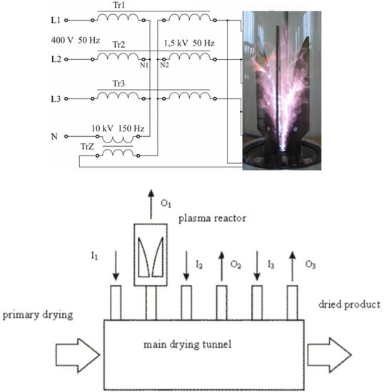
In the basic solution of the IPSS, three single-phase power transformers (Tr W), with magnetic circuits ensuring free return paths for higher harmonics of the magnetic flux, are fed from a symmetrical three-phase network [43,47]. The primary windings of the transformers are connected in a star (Y), while the secondary windings, depending on the type of non-thermal plasma reactor and the number of electrodes, can be connected in an open triangle (d) for DBD reactor—Figure 1a or 2—electrode GlidArc and in a star (y) when fed with a three- and multi-electrode GlidArc—Figure 1b.
Idea of the IPSS is based on the non-linearity of the power transformers’ cores. IPSS for DBD reactor is the well-known solution of the magnetic frequency tripler (mf3). Output voltage of the supplier has the tripled frequency of mains (150/180Hz), therefore the DBD plasma reactor running at three times increased frequency can be supplied at more than 30% lower voltage than at 50/60Hz having the same active power P [43]. Moreover, the voltage to the DBD plasma reactor can be easily adjusted (VR) by the impedance connected in series in the neutral conductor of the primary side of the PS, between the PEN and N terminals. In this way we get increase of frequency and voltage as well as its regulation in the one power supply of DBD reactor. In addition, reactive power compensation required in other transformer systems because of increased magnetic flux density is not necessary for the capacitive receiver that is the DBD reactor.
IPSS of GAD Multielectrode Plasma Reactors
Plasma-chemical reactions generated by the GAD take place directly in the polluted gas, therefore this kind of non-thermal plasma reactors have found applications in the treatment of flue gases emitted by industrial processes of coal and biomass combustion (SO2, NOx removing), painting and varnishing (VOC abatement), wastes utilization [47,52]. In all these processes non-thermal plasma should be generated in relatively large volume of chamber, with dimensions in the range of centimeters or even meters, unlike dimensions of DBD reactors discharge gaps of millimeters range. Multielectrode and multistage GAD plasma reactors are used in these applications to increase the time of the penetration of polluted gas by the non-thermal plasma, what is achieved by the connection of the discharge chambers in series with the gas flow, or in parallel, to divide the polluted gas stream into smaller streams [5].
Plasma reactors with GAD have different requirements for the power supply system than reactors with DBD. The ignition of the discharge should be realized at a voltage of several kilovolts (depending on the distance between the working electrodes), while the voltage on the discharge after ignition amounts to several hundred volts. This disproportion of ignition and stable operation voltages as well as the strong non-linearity of the conductance of the discharge creates a difficult task for the power supply system, which must have the properties of both a high-voltage ignition system and a system that delivers the power to the discharge chamber and follows the rapid time changes of the non-linear current-voltage characteristics of the GAD.
The name “integrated” was introduced by the authors with the idea of this system [43,48,49,50,51], for the following reasons, fundamental for the GAD plasma reactor operation: (1) Integration of the ignition function in the power supply, (2) sustaining discharge current at each passage through zero, and (3) ability to limit short-circuit current of PSS.
IPSS for the three-electrode GAD PR consists of four transformers—three power and one ignition—Figure 1b. Primary and secondary windings of the power transformers are connected in a star, with the secondary winding terminals connected to the plasma reactor electrodes WE1, WE2 and W3. The ignition transformer TR I is connected to a voltage that is induced between the PEN and N terminals of the primary side of the power transformers because of the non-linearity of the magnetization characteristics of their magnetic circuits. The UI voltage at the output of the ignition transformer having a 150/180Hz frequency, is sufficient to ionize the inter-electrode space, enabling ignition of the discharge between power transformers, which are designed and built for a voltage several times lower than the ignition voltage—Figure 2a. Three times higher frequency of the ignition voltage in relation to the power voltage frequency improves the ignition reliability and reduces power failure. Courses of working electrodes’ voltages are shown in Figure 2b.
Figure 3 presents courses of electrode current, phase voltage, and instantaneous power recorded for a three-electrode GAD plasma reactor fed from transformers with cores made of metallic glass (a) and a conventional transformer sheet (b). According to the oscillograph from Figure 3, the material of the power supply transformer core has a significant impact on the instantaneous phase voltage of the GAD PR. In the case of a core material made of metallic glasses, it will carry much more harmonics that come from ignition discharges systems. Reducing the content of higher harmonics in a system with amorphous cores is possible by using an ignition system operating at a technical frequency of 50 Hz. In the case of transformer sheet cores, higher harmonics are suppressed by the power supply’s magnetic circuit and do not occur in phase voltages—Figure 3b.
IPSS can also be used in three-wire network without an available neutral point, then the role of the neutral point is played by an artificial star point (N2), which can be implemented from three capacitors connected in a star (Figure 4).
Other integrated circuit solutions for feeding six and nine-electrode reactors are shown in Figure 5a,b [5,43].
Power supply system from Figure 5b owing to the three-stage connection of working electrodes—two of three working electrodes and one ignition electrode in each stage—allows to enlarge the space covered by the discharge and can be used to utilize exhaust gases at high flow rates, so as to extend the residence time of contaminated gas in the plasma space, which means its better decontamination.
3.2. A Five-Column Transformer as a Power Supply for a GAD Plasma Reactor
A modification of the integrated system is the use of a five-column transformer in the plasma reactor supply system. In typical designs of five-column transformers, magnetic flux closing through external columns is not in use. It was proposed to use the energy of the external columns’ fluxes in a three-phase five-column transformer. The idea of this solution is presented in Figure 6. The voltage induced in the windings of the external columns can be used to power the ignition system of the plasma reactor. In this way, the energy of the magnetic flux closing in these columns will be used to ionize the inter-electrode spaces of the GAD reactor.
Tests conducted on a 11 kVA laboratory model confirmed the validity of the idea of using a five-column transformer to power 3-electrode GAD reactors. In particular, they proved that it is possible to use the energy of magnetic fluxes closing through the outer columns of the transformer to ignite the GAD. Figure 7a presents the courses of ignition voltage and (b) between electrodes voltage of GAD reactor in argon as a processing gas [44,47].
The method of the reactor ignition system designing does not impose restrictions and it is possible to supply PRs without separate ignition circuits as well as with two-electrode and single-electrode ignition systems.
In all analyzed cases, the tested five-column transformer design performs the basic functions of the power supply, i.e.,: enables initial ionization of inter-electrode spaces, ignition of the discharge and its maintenance during the PR operation cycle, limiting the short-circuit current while ensuring the correct current value for plasma processes.
As an example of GAD plasma application, an installation of the exhaust gas purification from paint shop is presented [5,53]. GAD plasma reactor construction shown in Figure 8a consisted of one central ignition electrode and three working electrodes placed around the center of the discharge chamber in 2π/3 radians distance from each other. Technical specification of GAD reactor is given in Table 1.
Plasma burn-up of gases emitted from factory was tested using pilot-plant set-up installed in foundry’s production line. Gases polluted during painting and drying of foundry molds were mixed with hot air and emitted to the atmosphere via three chimneys. Average flow rate of gas was 2000 m3/h, temperature at the outlet was 150 degree centigrade. Main pollutants were heptane, toluene, xylene, butanol, terpentine, and ethyl acetate. In Table 2, laboratory scale experimental results are presented for propane and butane as pollutants. The ratio of pollutants varied in dependence on the used paint. Molds’ drying system with inlets (I), outlets (O), and GAD PR placed on one of the output chimneys is presented in Figure 8b.
Painted molds were consequently transported via primary drying unit to main drying tunnel, where hot air was dosed through the I1-I3 inlets. Polluted air from the main tunnel was evacuated through the chimneys O1-O3. The pilot plant plasma treatment system was installed on the O1 outlet. Investigated gas consisted of approximately 13% ethyl acetate, 10% benzene, 65% heptane, 6% toluene, 1% 1-butanol and less than 0.5 % of other chemical compounds on average (Table 3).
As it can be seen from Table 2 and Table 3, achieved treatment efficiency and percentage pollutants content, both at laboratory conditions and in the pilot plant plasma treatment system were quite satisfactory and it tended to decrease with relatively low ranging from 4 to 28 kWh for 1 kg of mineralized hydrocarbons (Table 2). Pollutants, after 30 min treatment time, were partly removed from the exhaust gas stream enabling hot air recovery in the future. The energetic efficiency of the process was considered sufficient and in a good accordance with literature data [54]. Pollutants’ concentration was much below the ignition level, which assured the safety of applied solution (Table 3). No signs of electrodes’ corrosion were noticed during the treatment procedure.
4. Power Electronics Supply Systems for NTPR
The use of static semiconductor voltage and frequency converters to NTPR is becoming more common and promising because of the enormous and ongoing progress in the field of semiconductor technologies, especially high power. There are many, based on power electronics, solutions of NTPR supply systems. Plasma reactors with DBDs, surface and co-planar discharges, atmospheric pressure plasma jets (APPJ) are often energized from frequency resonant converters, RF and pulse power systems, flyback and forward converters. Plasma reactors with arc discharges can be supplied with both direct and alternating voltage and pulse voltage [43,55].
Block diagrams of two basic constructions of DC power system of arc plasma reactors are presented in Figure 9. They consist of a bridge controlled on the secondary side of the matching transformer—Figure 9a or an AC controller on the primary side of the matching transformer—Figure 9b. Other solutions of DC arc power supply systems are modifications of the above mentioned structures.
Among the alternate current (AC) power supply system’s the AC/DC/AC are used to energize three and multielectrode arc plasma reactor. Highly efficient AC/DC/AC converters are more and more commonly applied in numerous applications of the plasma-chemical process. They enable adjustment of the voltage waveform, as well as the current, voltage, power and frequency regulation, for the purpose of a given plasma process. Block diagram of sixth electrode GAD power supply system is presented in Figure 10 [43,55].
The block diagram of the pulse power supply of a two-electrode micro-gliding arc discharge reactor (μGAD), in which to realize the main converter a symmetrical push-pull topology was used, is presented in Figure 11.
The block marked in Figure 11 as EMI (1) is responsible for the filtration of voltages entering the rectifier, marked as AC/DC block (2). The PFC block (3) soothes the ripples coming from the rectifier, improves the power factor, and provides a resource of quickly available direct current. The block marked as PWM (4) shapes the alternating voltage, usually rectangular with the desired frequency and duty cycle, while the last block marked AC/AC (5) is a high frequency pulse transformer. The design of the switching power supply for the NTP reactor is based on this standard block diagram, and is presented in more detail in the Section 4.2, while the selected problems of designing such power supplies, especially high frequency transformers are presented in chapter 5.
Typical resonant converter topology to energize DBD plasma reactor is presented in Figure 12 and is described in more detail in the Section 4.3 together with the example of application.
The block diagram of the RF radio frequency power supply system of the APPJ plasma reactor is shown in Figure 13 and example of its application is presented in Section 4.4.
4.1. AC/DC/AC PSS for a GAD Plasma Reactor
Idea of the AC/DC/AC inverter is presented in Figure 14. System can operate both as a current and voltage source. At the beginning, plasma reactor should be supplied from voltage source. Current-voltage characteristic of the plasma reactor changes considerably during its operation from the ignition to the extinction of the discharge. Discharge development from short arc, in the zone of ignition, to the glow discharge requires from the supply to follow-up discharge voltage increase proportional to the discharge length. At the steady-state operation, voltage changes depend on the processing gas parameters, while current should be kept at constant value, as to ensure plasma to be in non-thermal and non-equilibrium state. In general, the current inverter is energized from current source, which is realized with the series impedance coil attached between DC voltage source and inverter input. Output current has the rectangular waveform while voltage waveform depends on the load properties. Usually, capacitors are connected in parallel to the load of the current inverter. From the discharge point of view capacitance connected in parallel to the plasma reactor electrodes can significantly change its characteristics: higher capacitance can decrease the inter-electrode voltage and impair the thermal conditions of the GAD [55].
In the case the inverter operation as a current source, the output voltage of the supply in no-load is of rectangular form and output current waveform is forced as sine independently on the load character by means of pulse-width voltage modulation (PWM). Since, the GAD plasma reactor’s current has practically sine waveform at the whole range of operation parameters, while voltage waveform is distorted considerably—Figure 15a, therefore it is easier to control the power to the discharge through current value changes than voltage.
Moreover, the distorted discharge current, as it is when GAD PR is energized from the sine voltage source—Figure 15a, could faultily influence the control circuits of the inverter that may possibly result in the damage of its electronic modules. Courses of discharge voltage and current in the reactor energized from the AC/DC/AC inverter operating as a current source and a voltage source are shown in Figure 15a,b respectively. Strong voltage distortion is observed, while discharge current is sine as it is programmable forced in the supplier—Figure 15a.
4.2. Micro-Gliding Arc Discharge (μGAD) Power Supply System with Push-Pull Inverter
Two electrode micro-gliding arc discharges (μGADs) have found recently applications for agricultural and biomedical solutions [24,25,26,27,28,29]. They can be used for treatment and bactericidal decontamination of surfaces not resistant to high temperatures, like TEFLON, paper or materials for the packaging of food products, for seed germination and plants grow support as well for biomedical applications, like blood coagulation, wound healing, sterilization of tissues and medical equipment, in dermatology and even skin cancer therapy [18,19,57,58].
In the Figure 16 results of final temperature measurements on the surface of the sample with E-coli droplets in the function of gas composition are presented. Evidently, the E-coli bacteria colony was exterminated because of the plasma process, but not the heating process [59,60,61].
Power suppliers with push-pull topology are well-known, but their uses for supplying plasma reactors are relatively rare [62,63]. The supply shown on Figure 17 owes its beneficial properties to its topology. It has also the special feature of not having the switching overvoltages totally extinguished, as it happens in typical push-pull inverters. The overvoltage peaks that are dangerous for the transistor are the only ones to be cut off and the remaining ones move to the secondary coil. The correctly shaped overvoltages are used for improvement of ignition in GAD reactor [45,64].
The power supply with the block diagram shown in Figure 11 has a modular structure, whose mutual location is shown in Figure 17a. Development of the discharge is presented in Figure 17b. As can be seen from Figure 17 and Figure 18, the AC/DC bus (1) consists of two components: a rectifier with protective elements and a filter, which is equipped with a DC side capacitor pre-charging system, twin current control modules on the primary side (2) contain IGBTs with special drivers in their structure. Their inputs first of which has a 0° phase and the second one 180°.
They constitute links of the power path, and at their output alternating voltages VAC’ and VAC” are obtained with the frequency and duty cycle values set by the PWM control system (3). PWM controllers are implemented as two-output astable generators. Depending on the set value, pulse width modulation, and dead times, they perform the function of frequency control and soft start function. This module also has an error amplifier used in the feedback loop. With its help, the signal di can be used to influence the PWM value and control the primary current of the high frequency transformer. Block 4 is an auxiliary DC voltage source. Mains voltage is applied to its input and the output receives two stabilized direct voltages VDC and VDC* galvanically separated from the network voltage as well as from each other. The high-frequency transformer (5) receives on the primary side two counter-current alternating voltages, which transformed to the secondary side as alternating HV supply the NTP reactor.
In the middle tap of the transformer, the primary winding has a current transducer LEM (Figure 18), which is used to scale the instantaneous value of the primary current to the differential di signal. The signals marked as arrows in the Figure 17a do not symbolize electrical connections, but only demonstrate the path of energy conversion and control relationships established with the blocks. As it is mentioned, the important feature of the proposed push-pull pulse power supply is periodically obtained switching overvoltages (SO) that can be used for the GAD ignition improvement. Phenomenon is based on the parasitic parameters.
The fast-changing current in the coils representing leakage inductances and its derivative causes the energy pulsations and the formation of a flow that can be called commutation overvoltage. In their shaping to the form of dampened resonance, the RLC elements in the emitter collector circuit (R5, C2 and R6, C3) in Figure 18 contribute a lot. Basically, they shape the course of voltage in fluctuation. The switching overvoltages are transformed to the secondary side and increase the basic secondary voltage to the level ensuring ignition in the GAD reactor [64,65].
The switching overvoltages ignition improvement (SOII) simplifies the structure of a matching transformer, since the turn ratio can be of a lower value. Figure 19a depicts the output voltage waveform obtained in a PSPICE environment simulation of the system presented in Figure 18.
The appearing overvoltages (Figure 19) can be observed on the full secondary winding, but the observation is not very precise because of the parasitic capacitances existing on the secondary side of the HV transformer. Therefore they were recorded for 1 turn of the secondary winding in the no-load state. In the voltage waveform a boost by more than 60% is observable—Figure 19b. This is a really high improvement due to ignition reasons. Chosen issues connected with the design of HV and HF matching transformer for a push-pull pulse power supply are presented in chapter 5 [45,64].
4.3. DBDs Power System with Frequency Resonant Inverter
Electrical parameters of the DBD reactor depend on physical, chemical and technological conditions of the non-thermal plasma processes. These conditions are type of gas, its composition, electrode’s material and contaminations, temperature, humidity, flow rate, and all of them have an effect on reactor performance and ignition voltage value. From technological point of view, it is important to have the overall system efficiency as high as possible. The use of electrical resonance allows higher power supply efficiency and higher power density factor of the power electronic converter. Capacitive load, as the DBD reactor represents, naturally creates a freely oscillating resonant circuit with the inverter output inductive elements. Changes in the capacity of the reactor substantially affect the resonant frequency of the resonant circuit and, as a result on the operation of the inverter [36,56]. As an example the diagonal bridge resonant converter for an excitation of DBD reactor used in the diesel engine exhaust treatment system has been presented. Figure 20a shows diagonal bridge resonant converter construction and courses of current and voltage of DBD reactor energized from this system (b). DBD reactor construction for diesel engine exhaust treatment is shown in Figure 21a.
The overall efficiency of the power supply system, including the efficiency of resonant converter and the high voltage transformer, was 68%—Figure 21b. Resonant power supply system topology for DBD reactors allows continuous resonant frequency tracking and operation in reactor short–circuit state. An additional benefit is the property of transistor synchronization with the resonant capacitor voltage instead of the widely used method of distorted reactor current waveform synchronization.
4.4. RF Power Supply System of APPJ
APPJ belongs to a group of discharge plasma reactors whose demands for power supply system are very special, mainly because of the strong sensitivity of the V-I characteristics of power supply to changes of the receiver electrical parameters and necessity to limit value of current, to ensure a non-thermal plasma generation in the working space of APPJ [60,61,62,63,66,67,68,69,70,71,72,73,74,75].
The RF power supply should provide the appropriate voltage and power necessary for sustaining stable process parameters. Output characteristic of the sine wave generator is similar to the characteristics of the real current source with the characteristic impedance equal to 50 ohms and to maintain the relevant plasma process parameters the impedance of the receiver should be matched.
The inner rod electrode was powered by a regulated RF supply via impedance matching network (Figure 13). RF-frequency power supply of APPJ has been represented with a resonant sub-circuit depicted in Figure 22a. The most stable operation, which resulted in the lowest ratio of reflected power, depending on the feed gas type, was achieved at frequency range 12–15 MHz [60,61,73,74].
RF atmospheric pressure plasma jet has been used to enhance wettability of cellulose-based paper as a perspective platform for antibiotic sensitivity tests [69,70,71,72,73,74,75,76,77]. Helium and argon were the carrier gases for oxygen and nitrogen. Goniometric tests were performed for pure water and rape seed oil droplets. RF plasma jet allowed to decrease surface contact angle without changes in other features of tested material. Figure 23 presents results of contact angle measurements in function of treatment time for rapeseed oil 1 s after contact of a droplet with the paper surface [66,71,73].
5. Selected Issues of Designing Power Systems for NT Plasma Reactors
The design of electromagnetic power supplies for plasma reactors with barrier or gliding arc discharge involves, in principle, determining the design parameters of the transformers forming the power supply, either in the form of a magnetic multiplier, a five-column core, an integrated system of four single-phase transformers as well as transformers in the power electronic supplies. The work of these special transformers is based on the use of higher harmonics of the magnetic flux that induce an operating voltage with an increased frequency (in the case of reactors with barrier discharges) or the ignition voltage of discharges, as is the case in the integrated system and in the system with 5 column transformer. Therefore, the choice of material for the cores and the level of magnetic flux density becomes particularly important to ensure a high harmonic value of the magnetic flux.
The content of higher harmonics in the magnetic flux depends not only on the non-linearity of the magnetization characteristics, but also on the non-linear characteristics of the plasma reactor, and in the presence of a high frequency ignition circuit, also on the harmonics induced by this circuit, which can affect the operating voltage waveforms, and indirectly in the shape of a magnetic flux. As it results from the analyzes and tests of the gliding reactor power systems, the transformer core material can significantly change the voltage waveforms in the reactor and the ability of the power supply to carry higher harmonics generated in it (Figure 3). The material for transformer cores largely determines frequency processing, power transfer, losses and efficiency of the power supply [44,45]. The core material should meet the requirements of work with significant saturation of magnetic flux density of the magnetic circuit, and the shape of the magnetization characteristics and location of the operating point affect the output power and operating parameters of the power supply. The optimal core material should be characterized by a large value of the third harmonic B3h of magnetic flux density, low magnetizing current and small loss. These criteria are well met by materials with a high rectangularity coefficient, referred to as the ratio of magnetic flux density remanence Br to its saturation Bs. For commonly used electrical power transformer cores, the squareness factor is within 0.85–0.9, which ensures the third harmonic of magnetic induction approximately equal to 21% of the fundamental one. Increasingly, amorphous materials (metallic glasses) are used for transformer magnetic cores, which are characterized by a magnetization curve with high rectangularity and low magnetic flux density saturation. This allows the power supply to work with low losses and low magnetizing current. Currently, amorphous materials are available and their price is not much higher than conventional magnetic materials. GADs burn between electrodes located at a fixed distance and in media with constant pressure. Under these conditions, the discharge voltage practically does not depend on the wide-range of current changes. Therefore, the limitation of the current value on which the discharged power depends must be outside of the discharge. In the case of AC powered plasma reactors, an important issue is the reduction of non-current interruptions that deionize the discharge space, deteriorating the stability of the plasma reactor and the quality of the plasma generated in it.
Also, an important issue in the design of transformer power supplies for GAD plasma reactors discharge is to ensure the required leakage reactance that is defined as related to magnetic flux closing in air gaps and outside the core, linear inductance multiplied by angular frequency. According to previous studies, this leakage reactance should be 30–40% of short-circuit reactance for integrated power supply transformers [43,75,76,78]. Similar leakage reactance values are required in power supplies based on a five-column transformer [44]. This value is higher than in classic power transformers and lower than in arc welding power supply systems. Such a value of leakage reactance is difficult to obtain in constructions of coaxial windings, where it does not exceed 15%, or in structures with separated windings, where it is over 60%. The leakage reactance of the windings supplying the working electrodes of GAD reactor is shaped by appropriate allocation of the primary and secondary windings on the transformer columns. The highest value of leakage reactance is obtained in the case of disk windings. When there is one primary winding disc and one secondary winding disc, the leakage reactance is so high that in conventional transformers it causes an unacceptably high voltage loss. By changing the number of discs, one can change the value of reactance within wide limits while in concentric windings, can influence to some extent the value of leakage reactance by introducing spatial asymmetry of the windings.
Implementation of the matching HV and HF transformer to the pulse push-pull powers supply should assume the use of a core material that will be able to transfer frequencies in the range from (10–200) kHz, while frequencies in the range (10–25) kHz transfer most of the energy from the primary to the secondary in the form of a square wave. The ability to distribute high frequency pulses to the secondary side is only maintained because of the support of the reactor ignition by using commutation overvoltages. Many power ferrite powders are able to provide these parameters. The 3C90 core material was chosen for use in the push-pull power supply [45,59,64] whose own resonance frequency allows operation in a transformer up to 0.2 MHz. Impulse transformers made on the ferrite powder’s core allow achieving magnetic flux density B exceeding 0.3 T. Moreover, the transformer for the NTP power supply is not a typical device, because of the high-voltage secondary coil, which requires special electrical insulation strength. Additionally, high voltage requires the use of a core forming a large window in relation to the small cross-sectional area of the column to house windings. Primary and secondary windings should be placed on separate columns, which minimizes the risk of high voltages being transferred to the inverter side. Schematic structure of the secondary winding of the high frequency HV transformer is depicted in Figure 24A, while HV transformer picture is presented in Figure 24B [45,64].
Other issues related to the design of transformers for plasma reactor power systems do not have special features.
6. Conclusions
Non-thermal and non-equilibrium plasma can be generated by electrical discharges of almost any type. Cold plasma generation in vacuum or high vacuum conditions does not pose significant difficulties, even in high volume discharge chambers, but fabrication such a vacuum is expensive and requires special plasma reactor designs. Hence, there is a need to look for reactors in which cold non-equilibrium plasma can be generated under atmospheric pressure.
Promising plasma sources for industrial scale applications are reactors with discharges in the presence of a dielectric barrier, atmospheric pressure plasma jets and gliding arc in multi-electrode systems. In most applications, the design of the discharge chamber of the plasma reactor and its electrodes is not difficult, however, the use of plasma reactors on an industrial scale is determined by its power supply system, which must meet specific requirements, resulting mainly from the non-linearity of the receiver, which is the plasma reactor, working at high voltage and frequency and the need for ignition. Equally important in industrial conditions is the electromagnetic compatibility of plasma reactor supplies, which in the case of power electronic systems with microprocessor control, may require shielding and the use of filters to remove radiated and conducted interference from a non-linear receiver to the power electronic and then to the mains [79,80].
The main element of all plasma reactor power supply presented in the review is the transformer, which in appropriate implementation can meet most of the requirements for plasma power supplies. Owing to the transformer’s cores nonlinearity, simple, reliable, low cost and efficient power systems, especially suitable for industrial applications, can be constructed. Furthermore, transformer-based systems are much more resistant to radiated and conducted interference generated by electrical discharges. Some disadvantage of a transformer power supply is its relatively narrow range of the discharge power control.
AC/DC/AC inverters can operate both in the sine voltage or sine current regime. In the voltage regime inverter is suitable to supply DBD reactor while the current regime is most suitable to supply GAD reactor. Taking into account the electromagnetic compatibility, power supply system of GAD reactor with nonlinear transformers seems to be the better solution than electronic power inverter. Electronic modules of AC/ DC/AC inverter are sensitive for GADs’ origin interferences, that could propagate both through conduction and radiation and at some conditions can even destroy the supplier [80].
Push-pull topology using IGBT transistors to supply miniature gliding arc reactor allows to obtain the commutation auxiliary ignition in conditions of work with air as the plasma gas. Power supply has a high efficiency of energy processing above 91%, a wide scope of adjustment properties in the range of 13 kHz to 26 kHz and confirmed desired features in cooperation with the μGAD reactor. It guarantees the ignition of the discharge and maintains cyclical operation in a wide range of non-linearity parameters of the arc discharge resistance and generated plasma is very homogeneous both in air and in helium as processing gases [45].
The use of electrical resonance allows for higher power supply efficiency and higher power density factor of the power electronic converter. Resonant power supply system topology for DBD reactors, proposed in [56] allows continuous resonant frequency tracking. Precise identification of the APPJ power system parameters allow constructing efficient systems for the plasma treatment of the heat-sensitive surfaces.
Research on the properties and applications of non-thermal and non-equilibrium plasma at atmospheric pressure requires interdisciplinary cooperation of scientists representing both basic and applied sciences, let us mention: plasma chemistry and physics, biochemistry, microbiology, medicine, chemical technology, environmental engineering, material engineering, agricultural engineering, bioengineering, metrology and electrical engineering. The latter is represented by the author of this review, who, together with a team from the Department of Electrical Engineering and Electrotechnology of the Lublin University of Technology, for over 30 years conducts research on the generation of non-thermal plasma by means of electrical discharges, in particular on the power supply systems of these special energy receivers, in cooperation with the above-mentioned representatives of the basic and applied sciences. The research has resulted in many monographs, publications, doctorates and patents, most of which are cited in this review [9,11,12,13,14,15,16,20,21,22,23,24,25,26,27,28,29,30,34,36,37,41,42,43,44,45,47,48,49,50,51,52,53,55,57,58,59,60,61,65,66,67,68,71,72,73,74,75,76,77,78,79,80,81,82].
Conflicts of Interest
The authors declare no conflict of interest.
References
- Non-thermal Plasma Techniques for Pollution Control; Penetrante, M.; Shirley, E. (Eds.) Schultheis, NATO ASI Series G: Ecological Science, Part A and B; Springer: Berlin/Heidelberg, Germany, 1993; Volume 34. [Google Scholar]
- Roth, J.R. Industrial Plasma Engineering; Institute of Physics Publishing: Bristol, UK; Philadelphia, PA, USA, 1995. [Google Scholar]
- Kogelschatz, U. Dielectric barrier discharges: Their History, Discharge Physics and Industrial Applications. Plasma Chem. Plasma Process. 2003, 23, 1–4. [Google Scholar] [CrossRef]
- Jiang, B.; Zheng, J.; Qiu, S.; Wu, M.; Zhang, Q.; Yan, Z.; Xue, Q. Review on electrical discharge plasma technology for wastewater remediation. Chem. Eng. J. 2014, 236, 348–368. [Google Scholar] [CrossRef]
- Czernichowski, A.; Lesueur, H. Multi-electrodes high pressure gliding discharges reactor and its application for some waste gas and vapor incineration. In Proceedings of the Plasma Applied to Waste Treatment First Annual INEL Conference, Idaho Falls, ID, USA, 16–17 January 1991. [Google Scholar]
- Hasanbeigi, A.; Price, L. A technical review of emerging technologies for energy and water efficiency and pollution reduction in the textile industry. J. Clean. Prod. 2015, 95, 30–44. [Google Scholar] [CrossRef] [Green Version]
- Gavrilescu, M.; Demnerová, K.; Aamand, J.; Agathos, S.; Fava, F. Emerging pollutants in the environment: Present and future challenges in biomonitoring, ecological risks and bioremediation. New Biotechnol. 2015, 32, 147–156. [Google Scholar] [CrossRef] [PubMed]
- Carmen, F.; Szilagyi, H.; Hegyi, A. Environment and Pollution Management of Pollution Volatile Organic Compounds in Cluj-Napoca. Present Environ. Sustain. Dev. 2016, 10, 207–217. [Google Scholar] [CrossRef] [Green Version]
- Pawłat, J.; Wolny-Koładka, K.; Terebun, P.; Kwiatkowski, M.; Diatczyk, J.; Sudhakaran, M.S.P.; Mok, Y.S. Application of gliding arc plasma reactor for pre-treatment municipal wastes for alternative fuels production. In Proceedings of the 23rd International Conference on Advanced Oxidation Technologies for Treatment of Water, Air and Soil (AOTs-23), Clearwater Beach, FL, USA, 13–16 November 2017. [Google Scholar]
- Fridman, G.; Shereshevsky, A.; Peddinghaus, M.; Gutsol, A.; Vasilets, V.; Brooks, A.; Fridman, A. Bio-medical applications of non-thermal atmospheric pressure plasma. In Proceedings of the 37th AIAA Plasma dynamics and Lasers Conference, San Francisco, CA, USA, 5–8 June 2006. [Google Scholar]
- Pawłat, J.; Stryczewska, H.D.; Ebihara, K.; Mitsugi, F.; Sung, T.L. AOTs and solar energy for air, water and soil treatment. Trans. Mater. Res. Soc. Jpn. 2014, 39, 117–120. [Google Scholar] [CrossRef] [Green Version]
- Stryczewska, H.; Joanna Pawłat, J. Technologies of air, water and soil treatment based on solar energy and advanced oxidation processes. Mod. Power Eng. 2011, 1, 176–197. [Google Scholar]
- Komarzyniec, G.; Muszański, R.; Stryczewska, H.; Diatczyk, J. Solar powered ozone installation for water treatment in swimming pools. In Proceedings of the Workshop on Progress in New Methods of Water and Waste Water Cleaning, Gdańsk, Poland, 4–5 July 2011. [Google Scholar]
- Stryczewska, H.D.; Ebihara, K.; Muszański, R. Mobile installations of air, water and soil treatment with ozone. In Proceedings of the 23rd International Conference on Advanced Oxidation Technologies for Treatment of Water, Air and Soil (AOTs-23), Clearwater Beach, FL, USA, 13–16 November 2017; pp. 43–44. [Google Scholar]
- Yamashita, Y.; Yamashita, T.; Hashimoto, Z.; Ebihara, K.; Mitsugi, F.; Stryczewska, H.; Pawłat, J.; Teil, S.; Sung, T.L. Backpack-type ozone-mist sterilization system developed for non-chemical agriculture processes. In Proceedings of the 8th International Conference ELMECO-8 “Electromagnetic Devices and Processes in Environment Protection” Joint with 11th Seminar AoS-11 “Applications of Superconductors”, Nałęczów, Poland, 28 September–1 October 2014. [Google Scholar]
- Stryczewska, H.; Pawłat, J. Environmental and biomedical applications of gliding arc discharge plasma. In Proceedings of the 3rd International Conference on Photocatalytic and Advanced Oxidation Technologies for Treatment of Water, Air, Soil and Surfaces, Gdańsk, Poland, 1–4 September 2015. [Google Scholar]
- Miyamoto, K.; Ikehara, S.; Takei, H.; Akimoto, Y.; Sakakita, H.; Ishikawa, K.; Ueda, M.; Ikeda, J.; Yamagishi, M.; Kim, J.; et al. Red blood cell coagulation induced by low temperature plasma treatment. Arch. Biochem. Biophys. 2016, 605, 95–101. [Google Scholar] [CrossRef]
- Mitra, A.; Morfill, G.E.; Shimizu, T.; Steffes, B.; Isbary, G.; Schmidt, H.U.; Li, Y.F.; Zimmermann, Z.L. Applications in plasma medicine: A SWOT approach. Compos. Interfaces 2012, 19, 231–238. [Google Scholar] [CrossRef]
- Mohd Nasir, N.; Lee, B.K.; Yap, S.S.; Thong, K.L.; Yap, S.L. Cold plasma inactivation of chronic wound bacteria. Arch. Biochem. Biophys. 2016, 605, 76–85. [Google Scholar] [CrossRef]
- Niedźwiedź, I.; Adam Waśko, A.; Pawłat, J.; Polak-Berecka, M. The State of Research on Antimicrobial Activity of Cold Plasma. Pol. J. Microbiol. 2019, 68, 153–164. [Google Scholar] [CrossRef] [PubMed] [Green Version]
- Przekora, A.; Pawłat, J.; Terebun, P.; Duday, D.; Canal, C.; Hermans, S.; Audemar, M.; Labay, C.; Thomann, J.S.; Ginalska, G. The effect of low temperature atmospheric nitrogen plasma on MC3T3-E1 preosteoblast proliferation and differentiation in vitro. J. Phys. D Appl. Phys. 2019, 52, 1–10. [Google Scholar] [CrossRef]
- Takayama, M.; Ebihara, K.; Stryczewska, H.; Ikegami, T.; Gyoutoku, Y.; Kubo, K.; Tachibana, M. Ozone generation by dielectric barrier discharge for soil sterilization. Thin Solid Films 2006, 506, 396–399. [Google Scholar] [CrossRef]
- Komarzyniec, G.; Stryczewska, H.D.; Janowski, T.; Diatczyk, J. Special Transformers in Power Systems of Arc Plasma Reactors. In Proceedings of the 1st Central European Symposium on Plasma Chemistry, Gdańsk, Poland, 28–31 May 2006. [Google Scholar]
- Stryczewska, H.D.; Ebihara, K.; Takayama, M.; Gyoutoku, Y.; Tachibana, M. Non-Thermal Plasma-Based Technology for Soil Treatment. Plasma Process. Polym. 2005, 2, 238–245. [Google Scholar] [CrossRef]
- Stryczewska, H. Non-thermal plasma aided soil decontamination. In Proceedings of the 17th International Conference on Advanced Oxidation Technologies for Treatment of Water, Air and Soil (AOTs-17), San Diego, CA, USA, 7–10 November 2011. [Google Scholar]
- Ebihara, K.; Stryczewska, H.; Mitsugi, F.; Ikegami, T.; Sakai, T.; Pawłat, J.; Teil, S. Recent development of ozone treatment for agricultural soil sterilization and biomedical. Przegląd Elektrotechniczny 2012, 88, 92–94. [Google Scholar]
- Ebihara, K.; Mitsugi, F.; Ikegami, T.; Yamashita, Y.; Yamashita, T.; Hashimoto, Y.; Stryczewska, H.; Pawłat, J.; Teil, S.; Sung, T.L.; et al. Biological evaluation of gaseous ozone spray system for non-chemical sterilization. In Proceedings of the 8th International Conference ELMECO-8 “Electromagnetic Devices and Processes in Environment Protection” Joint with 11th Seminar AoS-11 “Applications of Superconductors”, Nałęczów, Poland, 28 September–1 October 2014. [Google Scholar]
- Ebihara, K.; Mitsugi, F.; Yamashita, Y.; Yamashita, T.; Baba, S.; Aoqui, S.; Mitsugi, F.; Ikegami, T.; Stryczewska, H. Ozone-mist sterilization and web-based management for greenhouse agriculture. In Proceedings of the International Conference on Electromagnetic Devices and Processes in Environment Protection with Seminar Applications of Superconductors (ELMECO & AoS), Nałęczów, Poland, 3–6 December 2017. [Google Scholar]
- Stryczewska, H.; Pawłat, J.; Ebihara, K. Plasma treatment for agriculture applications. In Proceedings of the 4th International Conference on Plasma Medicine—ICPM4, Orléans, France, 17–21 June 2012. [Google Scholar]
- Starek, A.; Pawłat, J.; Chudzik, B.; Kwiatkowski, M.; Terebun, P.; Sagan, A.; Andrejko, D. Evaluation of selected microbial and physicochemical parameters of fresh tomato juice after cold atmospheric pressure plasma treatment during refrigerated storage. Sci. Rep. 2019, 9, 1–11. [Google Scholar] [CrossRef] [Green Version]
- Pavlovich, M.J.; Ono, T.; Galleher, C.; Curtis, B.; Clark, D.S.; Machala, Z.; Graves, D.B. Air spark-like plasma source for antimicrobial NOx generation. J. Phys. D Appl. Phys. 2014, 47, 505202. [Google Scholar] [CrossRef]
- Li, S.; Tang, Z.; Gu, F. Experimental study on temperature characteristics and energy conversion in packed bed reactor with dielectric barrier discharge. Heat Mass Transf. 2010, 46, 851–857. [Google Scholar] [CrossRef]
- Hrycak, B.; Czylkowski, D.; Miotk, R.; Dors, M.; Jasinski, M.; Mizeraczyk, J. Hydrogen production from ethanol in nitrogen microwave plasma at atmospheric pressure. Open Chem. 2014, 13. [Google Scholar] [CrossRef]
- Diatczyk, J.; Giżewski, T.; Kapka, L.; Komarzyniec, G.; Pawłat, J.; Stryczewska, H. Generation of non-equilibrium low-temperature plasma in the array of gliding arc plasma reactors. In Proceedings of the 7th International Conference “Electromagnetic Devices and Processes in Environment Protection” Elmeco-7 Joint with 10th Seminar “Applications of Superconductors” AoS-10, Nałęczów, Poland, 28–30 September 2011. [Google Scholar]
- Kong, C.; Gao, J.; Zhu, J.; Ehn, A.; Aldén, M.; Li, Z. Characterization of an AC glow-type gliding arc discharge in atmospheric air with a current-voltage lumped model. Phys. Plasmas 2017, 24. [Google Scholar] [CrossRef] [Green Version]
- Stryczewska, H.D.; Jakubowski, T.; Kalisiak, S.; Giżewski, T.; Pawłat, J. Power systems of plasma reactors for non-thermal plasma generation. J. Adv. Oxid. Technol. 2013, 16, 52–62. [Google Scholar] [CrossRef]
- Stryczewska, H.D.; Komarzyniec, G. Properties of Gliding Arc (GA) Reactors Energized from AC/DC/AC Power Convectors. In Proceedings of the IEEE Region 8 SIBIRCON 2010 International Conference on Computational Technologies in Electrical and Electronics Engineering, Irkutsk, Russia, 11–15 July 2010; pp. 744–749. [Google Scholar]
- Selerowic, W.; Piechna, J.; Opalinska, T.; Ulejczyk, B. Experimental Investigation of the Dynamics and Space Range of the Gliding Arc in Three-Electrode System. IEEE Trans. Plasma Sci. 2011, 39, 2866–2867. [Google Scholar] [CrossRef]
- El-Zein, A.; Talaat, M.; El-Aragi, G.; El-Amawy, A. Experimental Model to Study the Characteristics of Gliding Arc Plasma Reactor with Argon/Nitrogen. J. Electr. Eng. 2015, 15, 64–67. [Google Scholar]
- Sun, S.R.; Kolev, S.; Wang, H.X.; Bogaerts, A. Investigations of discharge and post-discharge in a gliding arc: A 3D computational study. Plasma Sources Sci. Technol. 2017, 26, 05501. [Google Scholar] [CrossRef]
- Baba, T.; Takeuchi, Y.; Stryczewska, H.; Aoqui, S. A study of simple power supply system with 6 electrodes configuration on gliding arc discharge. In Proceedings of the 7th International Conference “Electromagnetic Devices and Processes in Environment Protection” Elmeco-7 Joint with 10th Seminar “Applications of Superconductors” AoS-10, Nałęczów, Poland, 28–30 September 2011. [Google Scholar]
- Jaroszyński, L. Analiza Plazmowego Reaktora Łukowego Wykorzystującego Nieliniowość Magnetowodów Transformatorów Układu Zasilającego (Analysis of the Plasma Arc Reactor Using the Nonlinearity of the Power Supply Transformers’ Magnetic Cores). Ph.D. Thesis, Lublin University of Technology, Lublin, Poland, 2000. (In Polish). [Google Scholar]
- Stryczewska, H.D. Technologie Plazmowe w Energetyce i Inżynierii Środowiska/Plasma Technologies in Energy and Environmental Engineering; Electrotechnical Committee of Polish Academy of Science PAN: Lublin, Poland, 2009; p. 212. ISBN 978-83-7497-070-9. (In Polish) [Google Scholar]
- Komarzyniec, G. Analiza Pracy Transformatora Pięciokolumnowego w Układzie Zasilania Łukowego Reaktora Plazmowgo (Analysis of the Five Column Transformer Operations in the Arc Plasma Reactor Supply). Ph.D. Thesis, Lublin University of Technology, Lublin, Poland, 2008. (In Polish). [Google Scholar]
- Krupski, L. Analiza Współpracy Przekształtnikowego Układu Zasilającego z Miniaturowym Generatorem Plazmy Nietermicznej (Analysis of Cooperation of the Converter Supply System with the Miniature Non-Thermal Plasma Generator). Ph.D. Thesis, Lublin University of Technology, Lublin, Poland, 2019. (In Polish). [Google Scholar]
- Billings, K.H.; Morey, T. Switch Mode Power Supply Handbook; McGraw-Hill: New York, NY, USA, 2011. [Google Scholar]
- Stryczewska, H.D.; Janowski, T.; Komarzyniec, G. Gliding Arc Discharge in the Triple-Electrode System. Acta Agrophysica 2002, 80, 63–70. [Google Scholar]
- Janowski, T.; Stryczewska, H. Hybrid Power Supply of Plasmotron to Carry-out Chemical Reactions. PL172,170. 29 August 1997. Available online: https://api-ewyszukiwarka.pue.uprp.gov.pl/api/collection/117ab1e1e5987b7e6818248ec00299aa#search=%22PL%20172170%22 (accessed on 5 May 2020).
- Janowski, T.; Stryczewska, H. AC Plasmotron for Chemical Reactions. PL172,152. 29 August 1997. Available online: https://api-ewyszukiwarka.pue.uprp.gov.pl/api/collection/ec86dc74cbff19fedc40ee50c35dd713#search=%22PL%20172152%22 (accessed on 5 May 2020).
- Stryczewska, H. Power System of Low Temperature Plasma Reactor. PL180,063. 29 December 2000. Available online: https://api-ewyszukiwarka.pue.uprp.gov.pl/api/collection/98c98b603f983f8ce62792f4d4f548c4#search=%22PL%20180063%22 (accessed on 5 May 2020).
- Stryczewska, H.; Janowski, T. Plasma Reactor Power Supply. PL193,498. 28 February 2007. Available online: https://api-ewyszukiwarka.pue.uprp.gov.pl/api/collection/f1746602d81bcea2e48941bb5a124814#search=%22PL%20193%20498,%20Janowski%22 (accessed on 5 May 2020).
- Pawłat, J.; Terebun, P.; Kwiatkowski, M.; Tarabová, B.; Kovaľová, Z.; Kučerová, K.; Machala, Z.; Janda, M.; Hensel, K. Evaluation of oxidative species in gaseous and liquid phase generated by mini-gliding arc discharge. Plasma Chem. Plasma Process. 2019, 39, 627–642. [Google Scholar] [CrossRef] [Green Version]
- Pawłat, J.; Diatczyk, J.; Stryczewska, H.D. Low-temperature plasma for exhaust gas purification from paint shop—A case study. Przegląd Elektrotechniczny 2011, 87, 245–248. [Google Scholar]
- Sobacchi, M.G.; Saveliev, A.V.; Fridman, A.A.; Gutsol, A.F.; Kennedy, L.A. Experimental assessment of pulsed corona discharge for treatment of VOC emissions. Plasma Chem. Plasma Process. 2003, 23, 347–370. [Google Scholar] [CrossRef]
- Stryczewska, H.D.; Sikorski, A.; Ruszczyk, A.; Komarzyniec, G. Gliding arc plasma reactor supplied from AC/DC/AC inverter. In Proceedings of the 18th International Symposium on Plasma Chemistry, Kyoto, Japan, 26–31 August 2007. [Google Scholar]
- Kalisiak, S.; Holub, M.; Jakubowski, T. Resonant inverter with output voltage pulse-phase-shift control for DBD plasma reactor supply. In Proceedings of the 13th European Conference on Power Electronics and Applications, Barcelona, Spain, 8–10 September 2009; pp. 1–9. [Google Scholar]
- Terebun, P.; Kwiatkowski, M.; Krupski, P.; Pawłat, J.; Diatczyk, J.; Janda, M.; Hensel, K.; Machala, Z. High speed camera imaging of mini glidarc discharge. In Proceedings of the SAPP 20th Symposium on Application of Plasma Processes, COST TD1208 Workshop on Application of Gaseous Plasma with Liquids, Tatranská Lomnica, Slovakia, 17–22 January 2015; pp. 283–287. [Google Scholar]
- Dasan, B.G.; Onal-Ulusoy, B.; Pawłat, J.; Diatczyk, J.; Sen, Y.; Mutlu, M. A new and simple approach for decontamination of food contact surfaces with gliding arc discharge atmospheric non-thermal plasma. Food Bioprocess Technol. 2016, 10, 1–12. [Google Scholar] [CrossRef]
- Krupski, P.; Kwiatkowski, M.; Terebun, P.; Pawłat, J.; Machala, Z.; Hensel, K. Zastosowanie reaktora plazmowego Miniaturized GlidArc w usuwaniu kontaminatu bakteryjnego z powierzchni teflonu/Application of the Miniaturized GlidArc plasma reactor in removing bacterial contamination from the surface of Teflon. Przegląd Elektrotechniczny 2016, 6, 127–130. (In Polish) [Google Scholar]
- Pawłat, J.; Samoń, R.; Stryczewska, H.D.; Diatczyk, J.; Giżewski, T. RF-powered atmospheric pressure plasma jet for surface treatment. Eur. Phys. J. Appl. Phys. 2013, 61. [Google Scholar] [CrossRef]
- Pawłat, J.; Samoń, R.; Giżewski, T.; Diatczyk, J.; Janowski, W.; Stryczewska, H. RF-powered atmospheric pressure plasma jet for surface treatment. In Proceedings of the HAKONE XIII: International Symposium on High Pressure Low Temperature Plasma Chemistry, Kazimierz Dolny, Poland, 9–14 September 2012. [Google Scholar]
- Ram, P.V.; Bhat, K.N.; Mala, R.C. Multiple output push-pull converter with post regulated buck converters. In Proceedings of the 2017 International Conference on Smart Grids, Power and Advanced Control Engineering (ICSPACE), Bangalore, India, 17–19 August 2017; pp. 231–236. [Google Scholar]
- Huiskamp, T.; Takamura, N.; Namihira, T.; Pemen, A.J.M. Matching a Nanosecond Pulse Source to a Streamer Corona Plasma Reactor with a DC Bias. IEEE Trans. Plasma Sci. 2015, 43, 617–624. [Google Scholar] [CrossRef] [Green Version]
- Krupski, P.; Stryczewska, H.D. The Investigation of the Properties of High-voltage Transformer in Nonthermal Plasma Pulse Power Supply. In Proceedings of the IEEE Explore-Post Conference Materials of 14th Selected Issues of Electrical Engineering and Electronics (WZEE) Conference, Szczecin, Poland, 19–21 November 2018; pp. 1–4. [Google Scholar]
- Krupski, P.; Stryczewska, H. System and Method of Supplying a Plasma Reactor with a Gliding Arc Discharge. PL233,868B1. 31 December 2019. Available online: https://api-ewyszukiwarka.pue.uprp.gov.pl/api/collection/d100bb62cb87548cc9a19c392e177dd2#search=%22PL%20193498%22 (accessed on 5 May 2020).
- Diatczyk, J.; Pawłat, J.; Stryczewska, H.D.; Krupski, P.; Terebun, P.; Kwiatkowski, M. Microplasma Reactor with an Adjustable Distance between the Electrodes for Surface Treatment. PL222,477. 29 July 2016. Available online: https://api-ewyszukiwarka.pue.uprp.gov.pl/api/collection/665450da4adc31070c7887a97be1cd16#search=%22PL%20222477%22 (accessed on 5 May 2020).
- Diatczyk, J.; Pawłat, J.; Stryczewska, H.D.; Terebun, P.; Kwiatkowski, M. The Method and Device for Generating Non-Equilibrium Low-Temperature Plasma. PL226,367. 31 July 2017. Available online: https://api-ewyszukiwarka.pue.uprp.gov.pl/api/collection/ee199f5e469792b48a81a5c6a8b274f1#search=%22PL%20226367%22 (accessed on 5 May 2020).
- Pawłat, J. Atmospheric pressure plasma jet for sterilization of heat sensitive surfaces. Przegląd Elektrotechniczny 2012, 10, 139–140. [Google Scholar]
- Dünnbier, M.; Schmidt-Bleker, A.; Winter, J.; Wolfram, M.; Hippler, R.; Weltmann, K.D.; Reuter, S. Ambient air particle transport into the effluent of a cold atmospheric-pressure argon plasma jet investigated by molecular beam mass spectroscopy. J. Phys. D Appl. Phys. 2013, 46, 435203. [Google Scholar] [CrossRef]
- Mounir, L.; Tamer, A. Arc-free atmospheric pressure cold plasma jets: A review. Plasma Proc. Polym. 2007, 4, 777–778. [Google Scholar]
- Kwiatkowski, M.; Terebun, P.; Krupski, P.; Diatczyk, J.; Pawłat, J.; Stryczewska, H. Angles on polymeric material exposed on plasma generated in dielectric barrier discharge plasma jet. In Proceedings of the 8th International Conference ELMECO-8 “Electromagnetic Devices and Processes in Environment Protection” Joint with 11th Seminar AoS-11 “Applications of Superconductors”, Nałęczów, Poland, 28 September–1 October 2014. [Google Scholar]
- Krupski, P.; Stryczewska, H. Thermal imaging of surfaces treated by cooled plasma jet. Przegląd Elektrotechniczny 2018, 94, 79–82. [Google Scholar] [CrossRef] [Green Version]
- Pawłat, J.; Terebun, P.; Kwiatkowski, M.; Diatczyk, J. RF atmospheric plasma jet surface treatment of paper. J. Phys. D Appl. Phys. 2016, 49, 374001. [Google Scholar]
- Pawłat, J.; Terebun, P.; Kwiatkowski, M.; Krupski, P.; Diatczyk, J.; Murakami, T. Surface treatment of high-impact polystyrene using RF-APPJ. In Proceedings of the SAPP 20th Symposium on Application of Plasma Processes, COST TD1208 Workshop on Application of Gaseous Plasma with Liquids, Tatranská Lomnica, Slovakia, 17–22 January 2015; pp. 310–313. [Google Scholar]
- Stryczewska, H.D. Analiza Pracy Magnetycznego Potrajacza Częstotliwości Jako Źródła Zasilania Odbiornika Nieliniowego na Przykładzie Wytwornicy Ozonu (Analysis of Magnetic Frequency Tripler Operation as a Power Source for a Non-linear Receiver on the Example of an Ozone Generator). Ph.D. Thesis, Lublin University of Technology, Lublin, Poland, 1986. (In Polish). [Google Scholar]
- Stryczewska, H.D. Elektromagnetyczny Układ Zasilania Reaktorów Plazmowych ze Ślizgającym się Wyładowaniem Łukowym; Series: Elektryka; LUT University Publisher: Lublin, Poland, 1998; p. 146. ISBN 83-87270-82-2. (In Polish) [Google Scholar]
- Stryczewska, H.D. Analiza Zintegrowanych Zasilaczy Elektromagnetycznych w Urządzeniach Wyładowczych; Series: Elektryka; LUT University Publisher: Lublin, Poland, 1996; p. 132. (In Polish) [Google Scholar]
- Terebun, P. Wpływ Parametrów Reaktora APPJ o Częstotliwości Radiowej na Skuteczność Modyfikacji i Dekontaminacji Powierzchni. Ph.D. Thesis, Lublin University of Technology, Lublin, Poland, 2019. (In Polish). [Google Scholar]
- Mazurek, P.; Pawłat, J. Badania natężeń pól elektrycznych i magnetycznych generowanych przez instalację reaktorów plazmowych. Rocz. Ochr. Srodowiska Annu. Set Environ. Prot. 2016, 18, 567–578. [Google Scholar]
- Mazurek, P. Selected methods to improve the electromagnetic compatibility of the plasma reactor. Przegląd Elektrotechniczny 2012, 88, 158–160. [Google Scholar]
- Pawłat, J. Electrical Discharges in Humid Environments. Generators, Effects, Application; LUT University Publisher: Lublin, Poland, 2013; p. 141. ISBN 978-83-63569-37-2. [Google Scholar]
- Diatczyk, J. Badanie Pola Temperatury w Komorze Wyładowczej Reaktora Plazmowego. Ph.D. Thesis, Lublin University of Technology, Lublin, Poland, 2007. (In Polish). [Google Scholar]
Figure 1.
Integrated power supply system (IPSS) for dielectric barrier discharge (DBD) plasma reactor (PR) (a) and for gliding arc discharge (GAD) PR (b), where: Tr W—power transformer, VR—voltage regulation, Tr I—ignition transformer, WE—working electrodes, IE—ignition electrode, YNd-3-phase transformer with star-delta connection with neutral wire (N) on the primary side, YNyn-3-phase transformer with star-star connection with neutral wires on the both transformer sides [43,48,49,50,51].

Figure 2.
(a) Characteristics of the IPSS (A-B ignition voltage characteristic, B–C operating voltage characteristic); (b) phase voltages uf1(t), uf2(t) and uf3(t) on the 3-electrode GAD reactor during the discharge in air at flow rate of 10 lit/min, supply voltage frequency f = 50Hz.
Figure 2.
(a) Characteristics of the IPSS (A-B ignition voltage characteristic, B–C operating voltage characteristic); (b) phase voltages uf1(t), uf2(t) and uf3(t) on the 3-electrode GAD reactor during the discharge in air at flow rate of 10 lit/min, supply voltage frequency f = 50Hz.

Figure 3.
Oscillographs of electrode current IGAD, phase voltage UGAD and discharge power pGAD(t), when feeding the GAD reactor from transformers with cores made of: (a) Amorphous glass, (b) transformer sheet; on both oscillographs frequency of ignition voltage is equal to 20 kHz, process gas—Argon, flow rate 1 m3/h, RMS voltage UGAD = 250 V, RMS current IGAD = 2.2 A, supply voltage frequency f = 50 Hz.

Figure 4.
IPSS with artificial neutral point from three capacitors connected in star—N2 artificial neutral point, N1 and n—neutral points according to primary and secondary side of transformers Tr1, Tr2, and Tr3 connected in star [43].
Figure 4.
IPSS with artificial neutral point from three capacitors connected in star—N2 artificial neutral point, N1 and n—neutral points according to primary and secondary side of transformers Tr1, Tr2, and Tr3 connected in star [43].

Figure 5.
(a) IPSS for six electrode; (b) nine electrode GAD reactor (TrZ—ignition transformer) [5,43].

Figure 6.
A 5-column transformer with external wound columns and a magnetic circuit made of wound cores; (a) windings connection—external column windings connected in series; (b) arrangement of working and ignition coils on wound cores, 1/2—concentrically wound primary and secondary windings, 3—windings of external columns designed for supplying ignition systems of GAD plasma reactor [23,44].

Figure 7.
(a) Ignition voltage Uign waveform (distance between ignition electrodes 5 mm) when supplied from external windings connected in series of the five-column transformer (b) voltage UGAD between electrodes of GAD reactor in argon, at a the primary voltage of 90V, [44].
Figure 7.
(a) Ignition voltage Uign waveform (distance between ignition electrodes 5 mm) when supplied from external windings connected in series of the five-column transformer (b) voltage UGAD between electrodes of GAD reactor in argon, at a the primary voltage of 90V, [44].

Figure 8.
(a) GAD plasma reactor; (b) drying system in the paint shop, (I1, I2, I3)—hot air inlets, (O1, O2, O3)—polluted air outlets.
Figure 8.
(a) GAD plasma reactor; (b) drying system in the paint shop, (I1, I2, I3)—hot air inlets, (O1, O2, O3)—polluted air outlets.

Figure 9.
DC power systems of arc discharge reactor (ADR) with: (a) A controlled bridge (R) on the secondary side of the transformer (Tr); (b) with an AC controller (I) on the primary side of the transformer.
Figure 9.
DC power systems of arc discharge reactor (ADR) with: (a) A controlled bridge (R) on the secondary side of the transformer (Tr); (b) with an AC controller (I) on the primary side of the transformer.

Figure 10.
Block diagram of AC/DC/AC power supply systems for sixth electrode GAD reactor, where L—line choke; F—controlled rectifier, C—filters/DC bus; T—converters with the ability to adjust the offset between the output signals, Tr—boosting transformer; PC—capacitors pre-charging system; PS—protection system in disconnected states; M—microcontroller [55].

Figure 11.
Block diagram of the pulse power supply as a functional block chain.

Figure 12.
Resonant converter topology for DBD plasma reactor [56].
Figure 12.
Resonant converter topology for DBD plasma reactor [56].

Figure 13.
Block diagram of the RF-frequency power supply of atmospheric pressure plasma jets (APPJ).
Figure 13.
Block diagram of the RF-frequency power supply of atmospheric pressure plasma jets (APPJ).

Figure 14.
Scheme connection of the AC/DC/AC power supply system of the sixth electrode GAD rector for decomposition of volatile organic compounds (VOCs) emitted during industrial processes [55].
Figure 14.
Scheme connection of the AC/DC/AC power supply system of the sixth electrode GAD rector for decomposition of volatile organic compounds (VOCs) emitted during industrial processes [55].

Figure 15.
Discharge voltage (blue signal) and current (yellow signal) waveforms while energized form AC/DC/AC inverter: (a) In the current source regime—current is sine; (b) in the voltage source regime—voltage is sine; process gas—Argon at flow rate 2 m3/h.
Figure 15.
Discharge voltage (blue signal) and current (yellow signal) waveforms while energized form AC/DC/AC inverter: (a) In the current source regime—current is sine; (b) in the voltage source regime—voltage is sine; process gas—Argon at flow rate 2 m3/h.

Figure 16.
(a) Final temperature in degrees centigrade on the surface of the sample in function of gas composition—N2, O2, and CO2 and their mixtures—, (b) E-coli bacteria samples treated by μGADs, distance between the top of electrodes and the sample 21 mm [59].
Figure 16.
(a) Final temperature in degrees centigrade on the surface of the sample in function of gas composition—N2, O2, and CO2 and their mixtures—, (b) E-coli bacteria samples treated by μGADs, distance between the top of electrodes and the sample 21 mm [59].

Figure 17.
(a) Block diagram of the of NTP power supply for 2 electrode GAD reactor, based on push—pull topology, 1—AC/DC bus with, 2—twin current control modules, 3—PWM control system, 4—auxiliary DC voltage, 5—HV and HF transformer with divided primary winding, (b) development of the μGAD in air at flow rate 450 dm3/h—above photo and below image recorded with a fast speed camera [64].

Figure 18.
Simplified diagram of high-voltage pulse power supply of two electrode μGAD plasma reactor [64].
Figure 18.
Simplified diagram of high-voltage pulse power supply of two electrode μGAD plasma reactor [64].

Figure 19.
(a) Output voltage waveform obtained in a PSPICE environment simulation, (b) same voltage waveform (signal 3) measured in 1 turn of the secondary side of the HV transformer.
Figure 19.
(a) Output voltage waveform obtained in a PSPICE environment simulation, (b) same voltage waveform (signal 3) measured in 1 turn of the secondary side of the HV transformer.

Figure 20.
(a) Diagonal bridge resonant converter for DBD reactor excitation, (b) DBD current and voltage waveforms [56].
Figure 20.
(a) Diagonal bridge resonant converter for DBD reactor excitation, (b) DBD current and voltage waveforms [56].

Figure 21.
DBD reactor construction for diesel engine exhaust treatment (b) results of efficiency measurements of power electronic diagonal bridge resonant converter [36,56].

Figure 22.
(a) APPJ power supply system with separated resonant sub-circuit. (b) Picture of the reactor.
Figure 22.
(a) APPJ power supply system with separated resonant sub-circuit. (b) Picture of the reactor.

Figure 23.
Contact angle versus treatment time for rapeseed oil (90 g/m2) measured 1 s after a droplet contact with the paper surface, at 3 cm distance between the paper surface and a nozzle of the APPJ [71,73].

Figure 24.
(A) Schematic structure of the secondary winding of the high frequency transformer, where a) total windings’ cross-section with the core, b) enlarged section fragment with one coil, c) layer diagram, where 1—core, 2—carcass 3—insulation coil, 4—winding wire, 5 and 6—interlayer insulation, (B)—picture of the HF transformer [45,64].


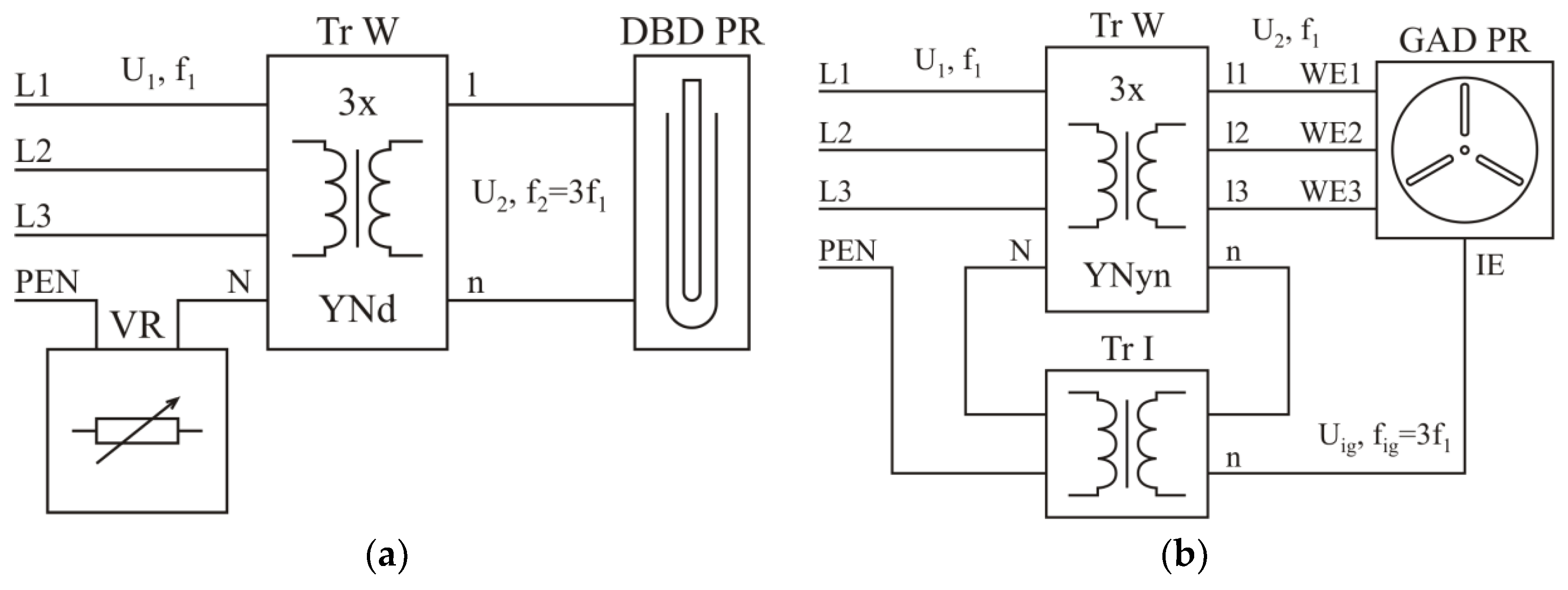
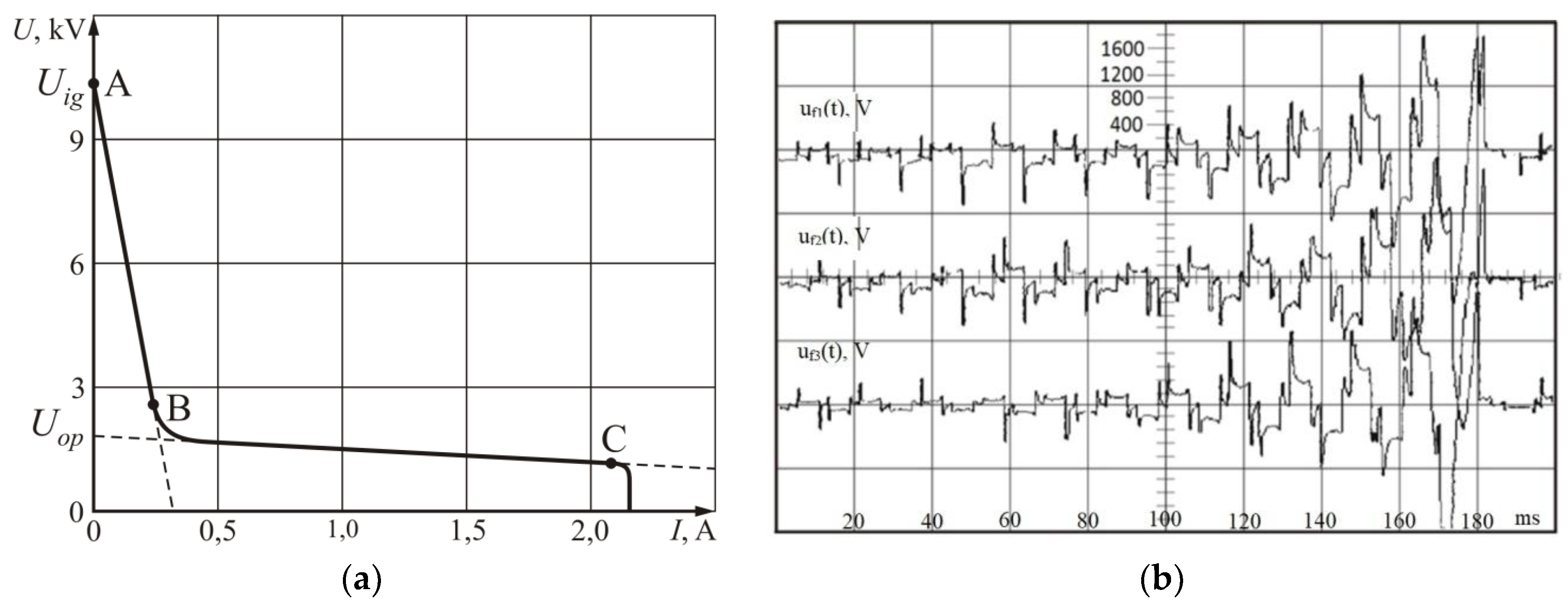
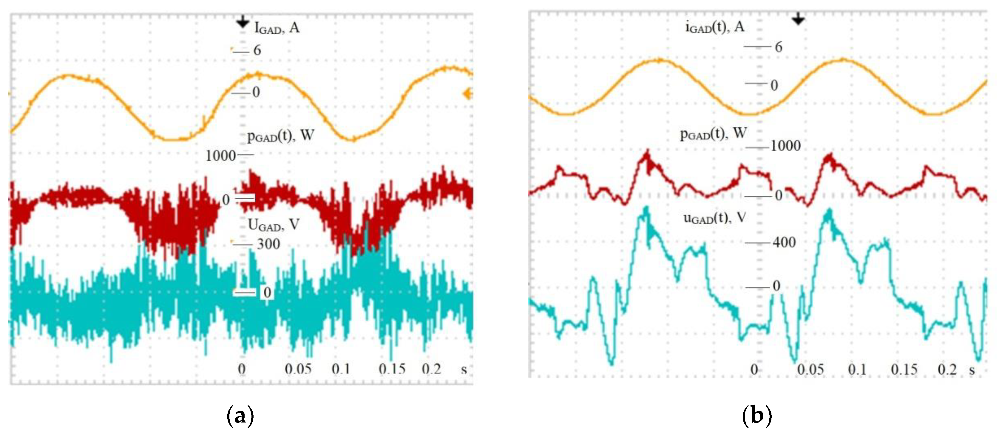
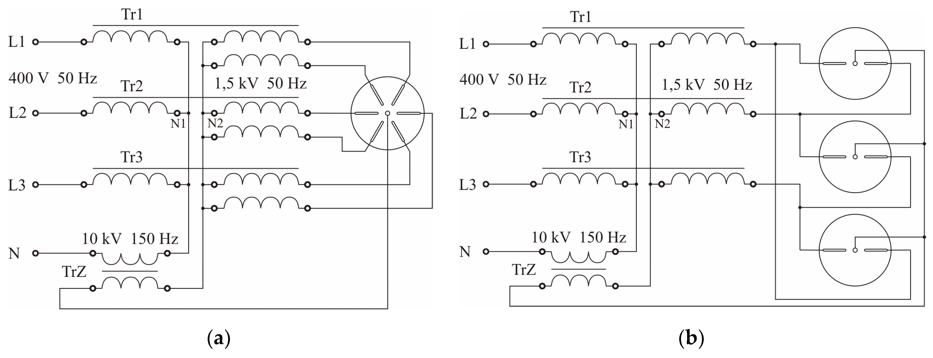
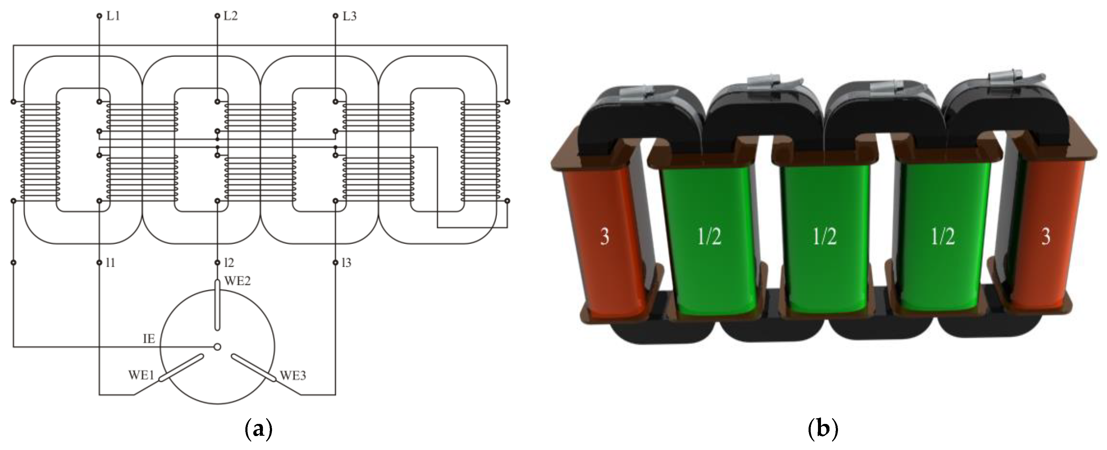
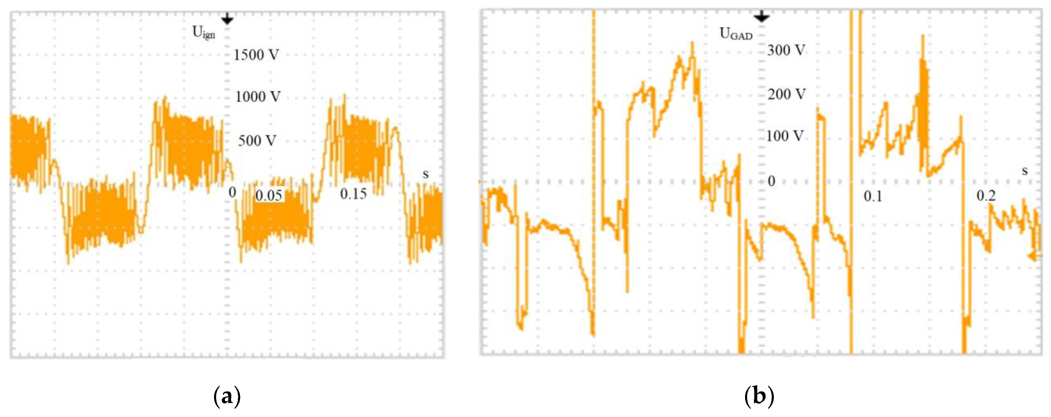
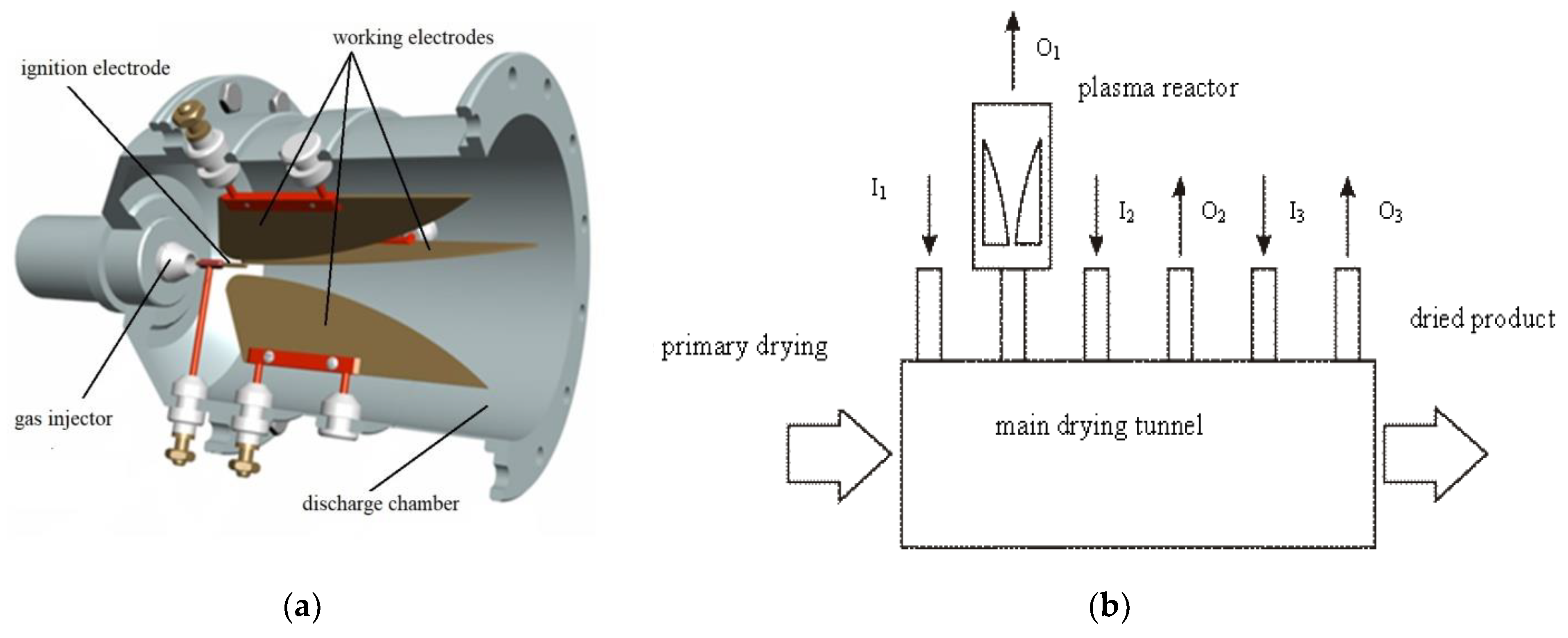
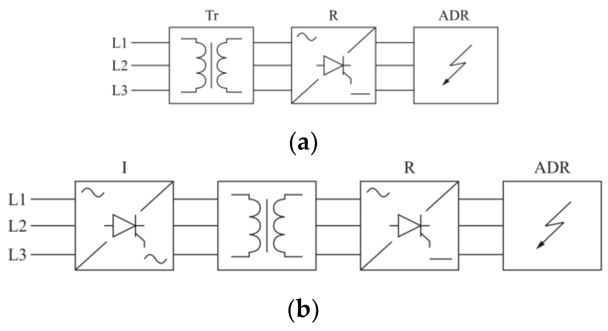
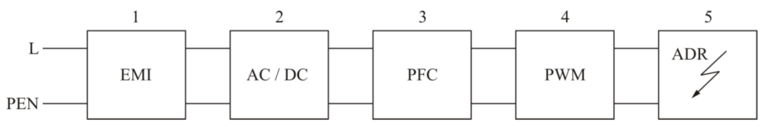
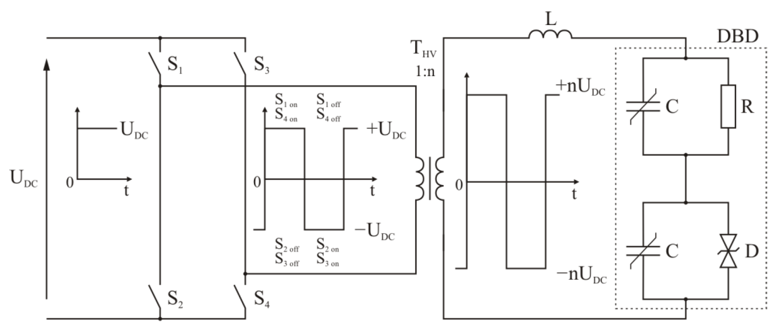
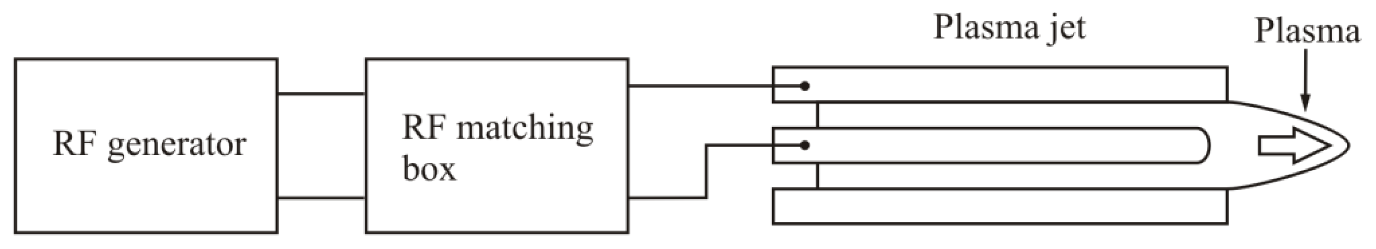
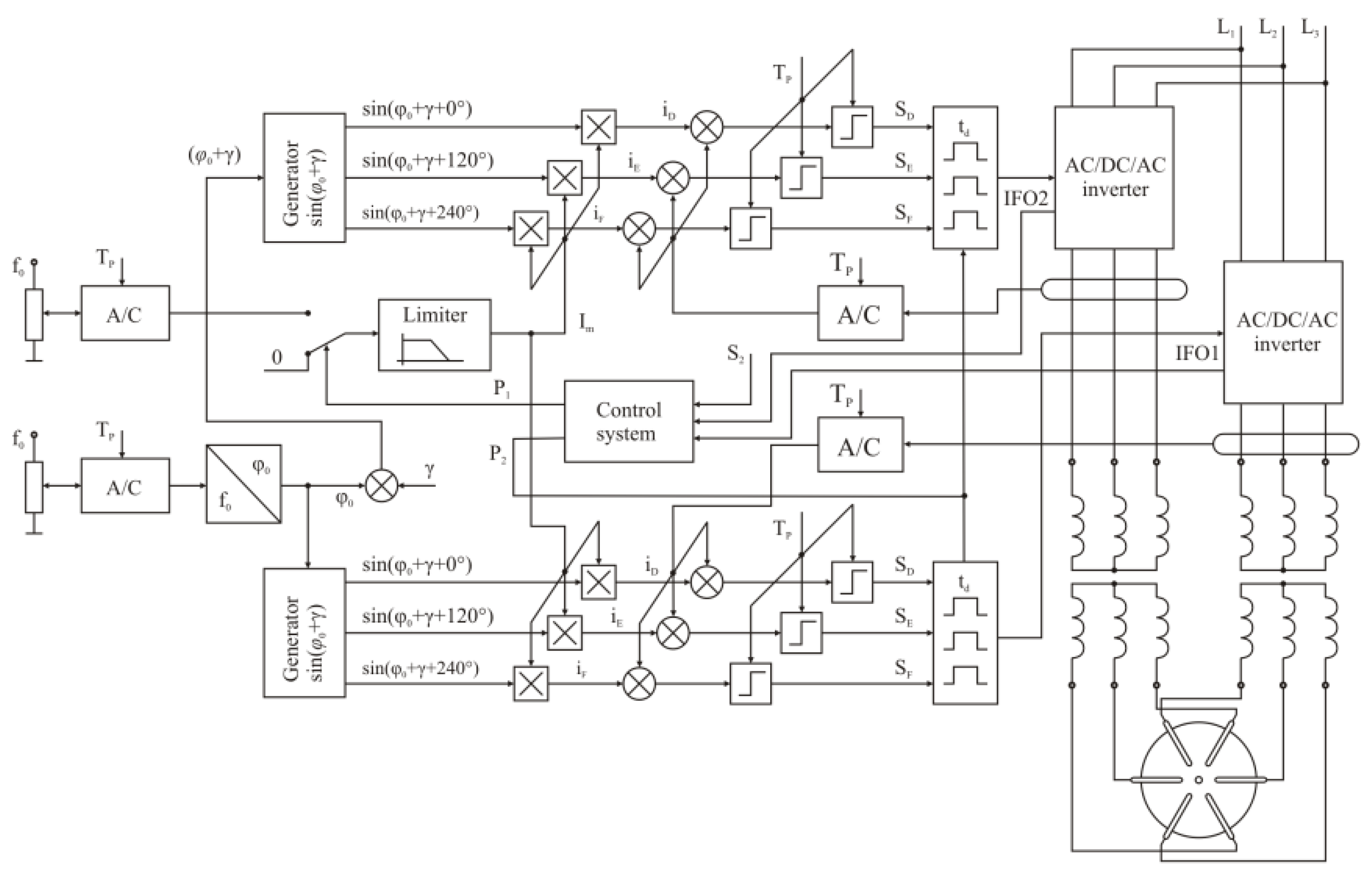
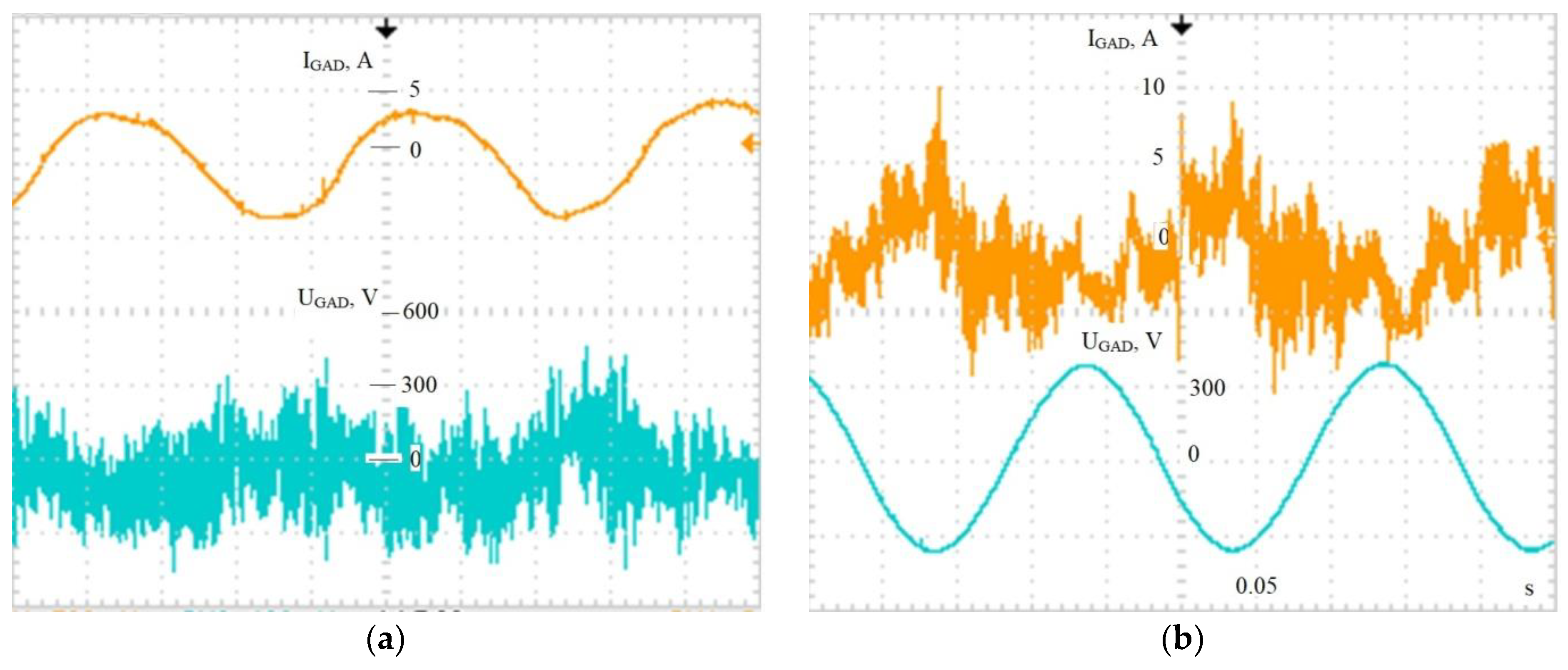
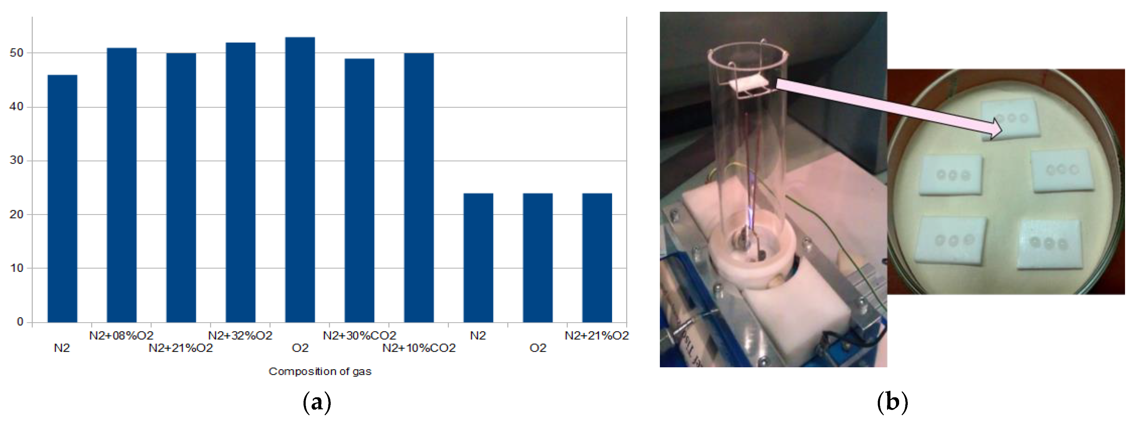
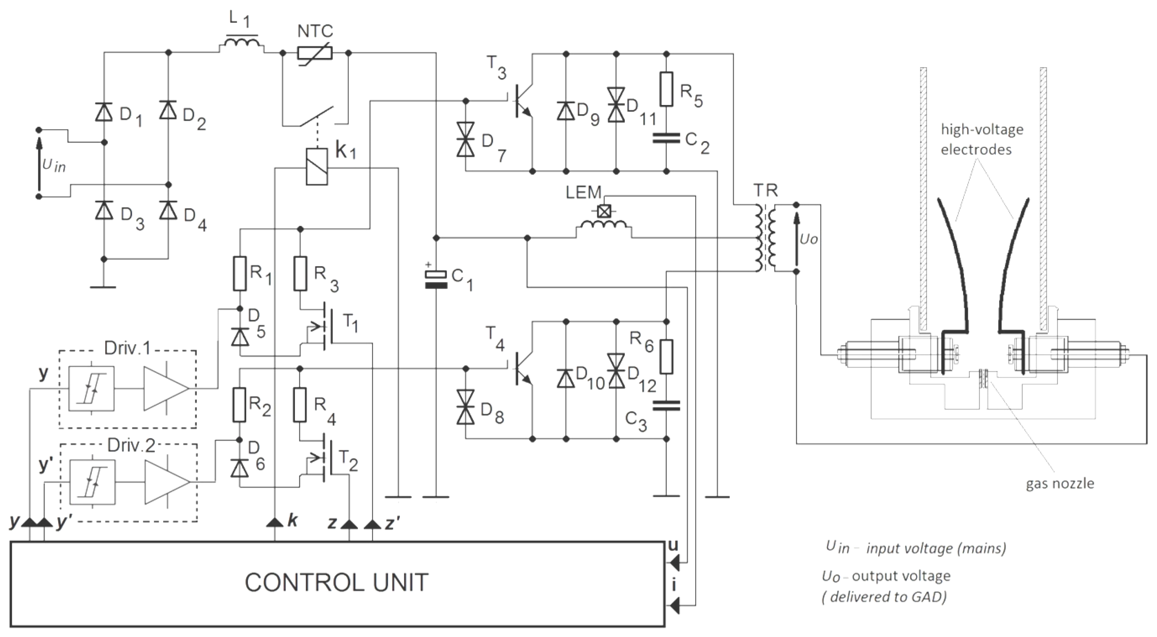
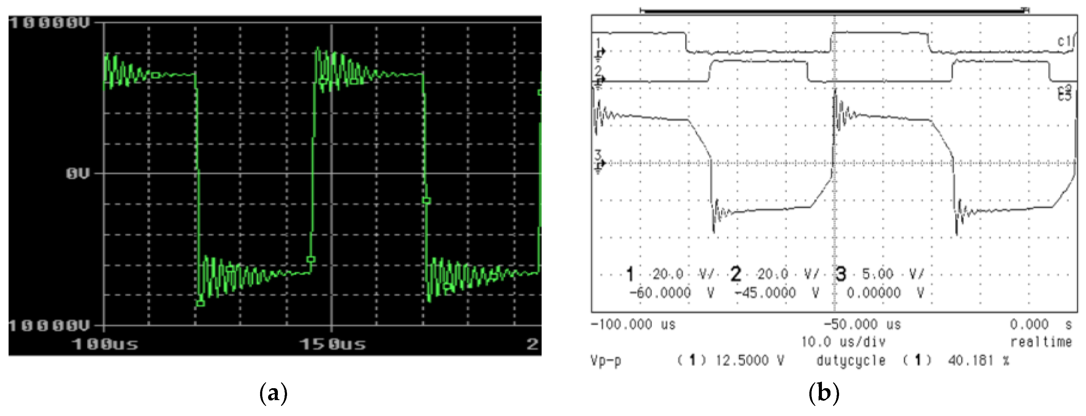
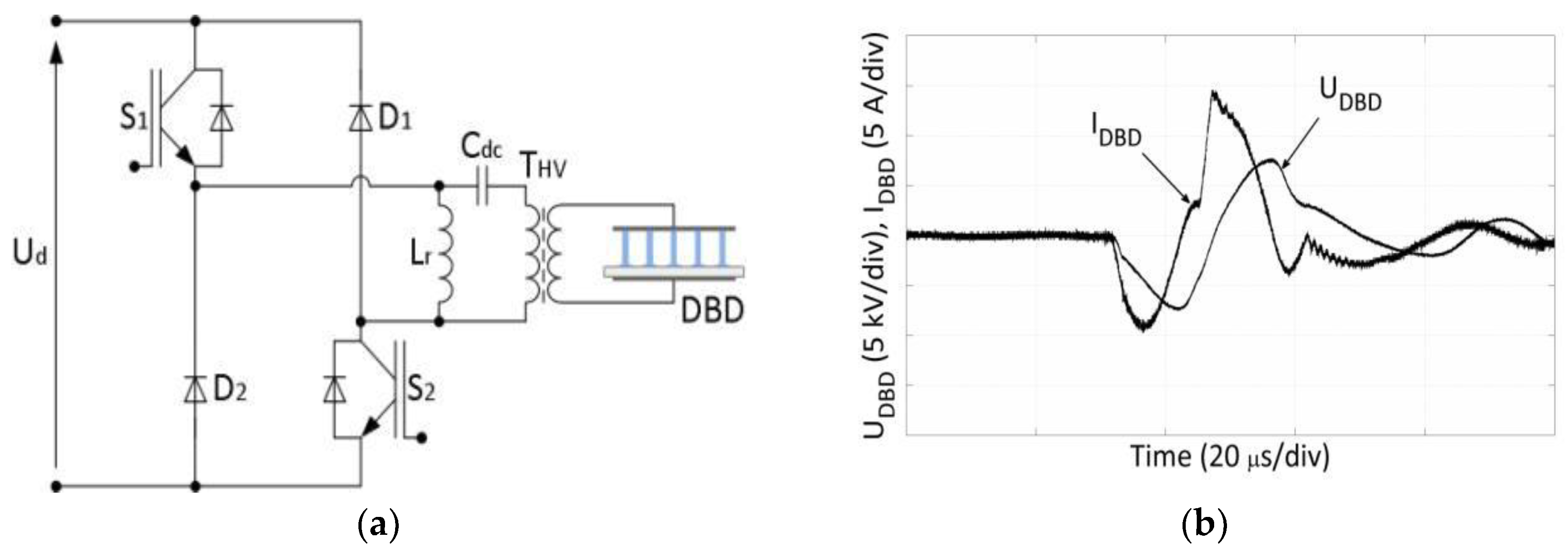
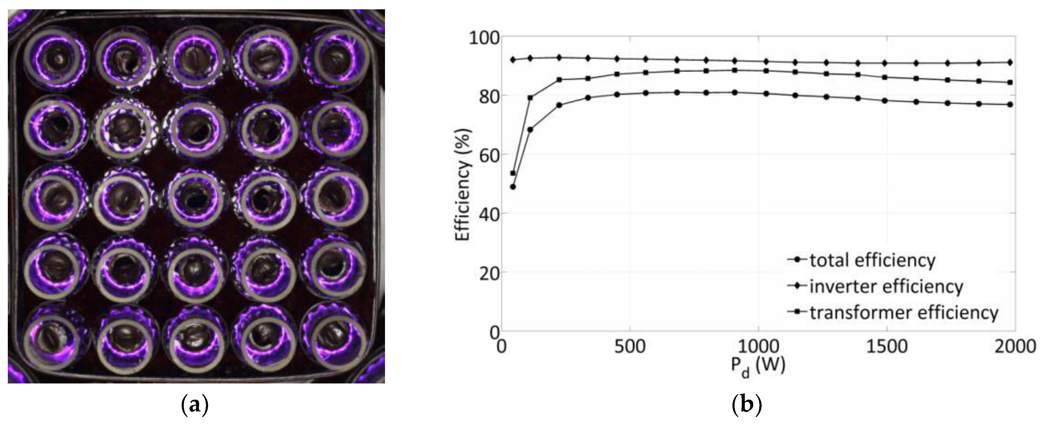
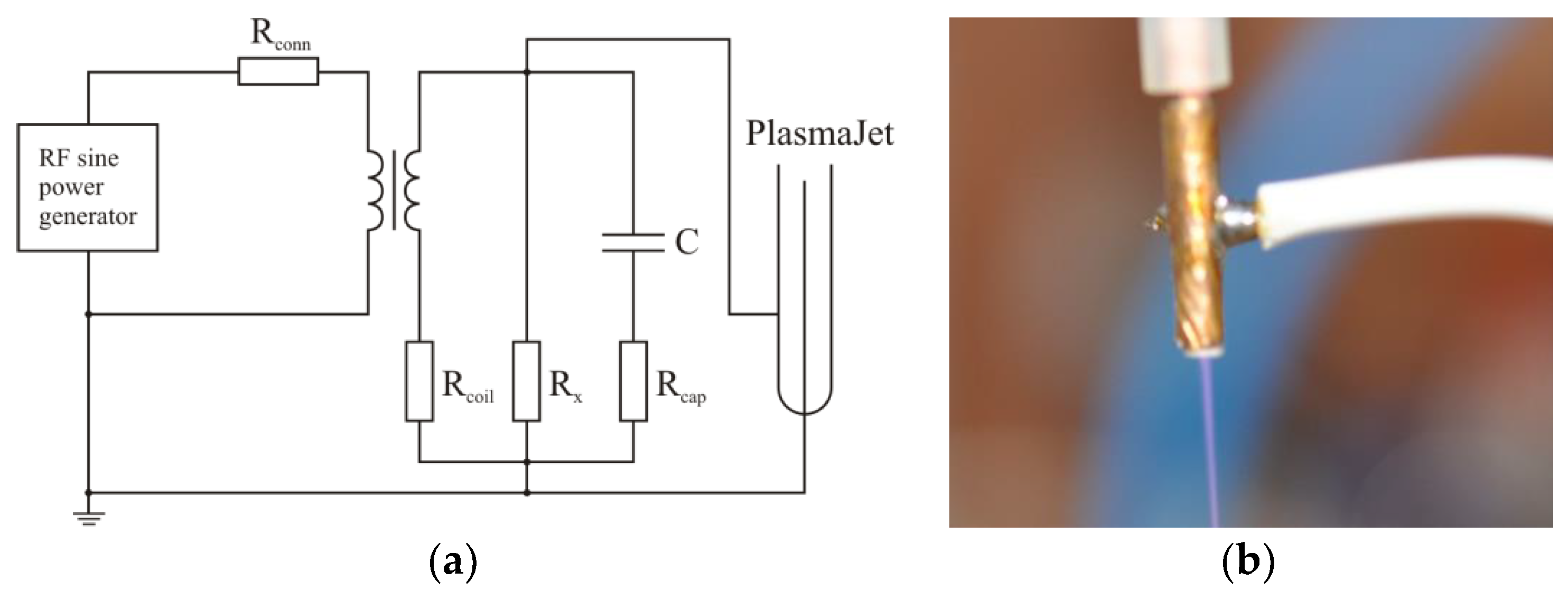
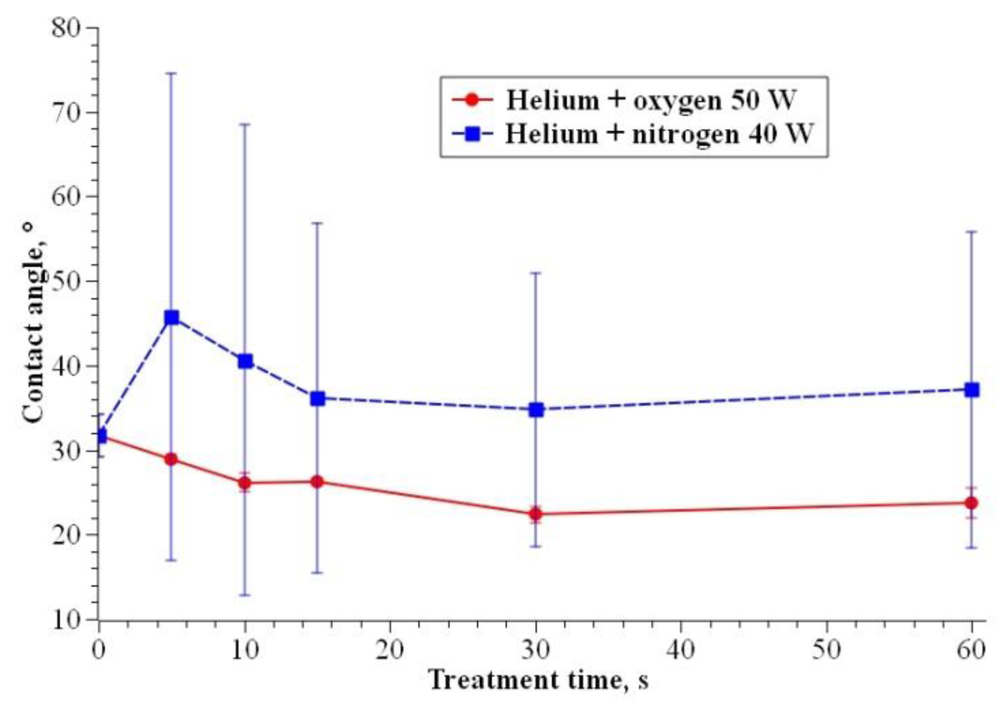
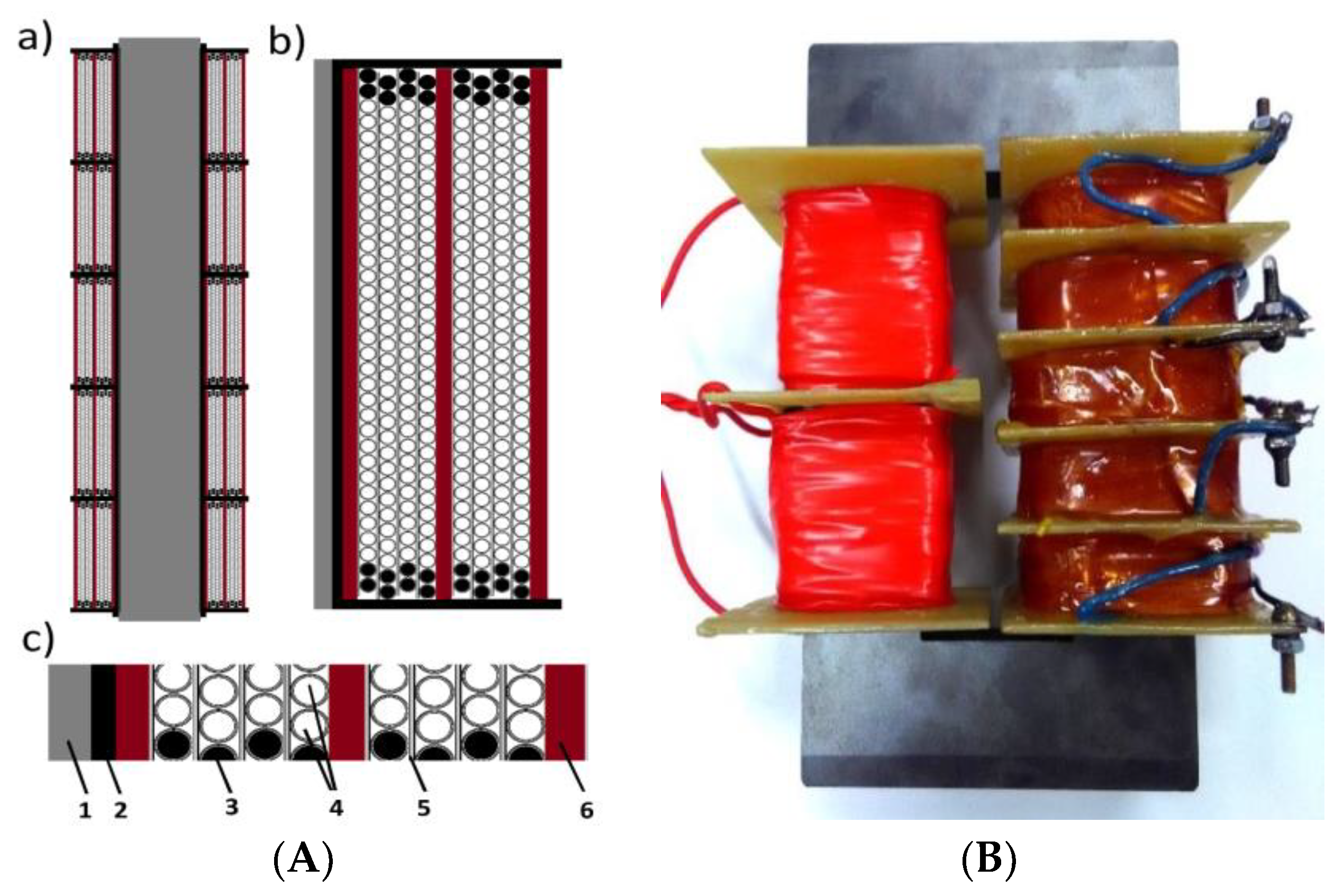
Table 1.
Technical specification of GAD reactor [53].
Table 1.
Technical specification of GAD reactor [53].
| Height of Reaction Chamber | 500 mm |
| Diameter of reaction chamber | 114 mm |
| Ignition electrode material | Tungsten 1 mm |
| Working electrodes material | acid proof steel 0H18N |
| Number of working electrodes | 3 |
| Length of working electrodes | 210 mm |
| Distance between electrodes in the ignition/ quenching zones | 5mm/50mm |
| Gas flow rate | (0.5–20) m3/h |
Table 2.
Laboratory experimental results [53].
Table 2.
Laboratory experimental results [53].
| PROPANE | BUTANE | ||||
|---|---|---|---|---|---|
| Initial concentration (volume) | % | 1.26 | 0.48 | 0.85 | 0.345 |
| Abatement level | % | 54 | 22 | 47 | 19 |
| Flow rate | m3 /h | 74 | 88 | 75 | 87 |
| Active power | kW | 4.3 | 3.8 | 4.2 | 4.1 |
| Gas temperature (inlet) | °C | 25 | 22 | 28 | 28 |
| Gas temperature (outlet) | °C | 410 | 188 | 400 | 210 |
| SEI kWh/m3 | 0.057 | 0.044 | 0.056 | 0.047 | |
| SER kWh/kg | 4.3 | 21 | 5.4 | 28 | |
Table 3.
Gas chromatography results of volatile organic compound (VOC) treatment [53].
Table 3.
Gas chromatography results of volatile organic compound (VOC) treatment [53].
| Chemical Compound | Measurement 1 at Air Mixture Velocity 4 m/s | Measurement 2 at Air Mixture Velocity 6m/s | ||||
|---|---|---|---|---|---|---|
| Retention Time | Amount of Pollutants % | Retention Time | Amount of Pollutants % | |||
| min | before Treatment | after Treatment | min | before Treatment | after Treatment | |
| methyl ethyl ketone | 13.78 | 0.38 | 7.38 | 13.749 | 0.28 | 4.70 |
| ethyl acetate | 14.85 | 13.39 | 9.20 | 14.828 | 13.37 | 8.96 |
| 1-butanol | 18.47 | 1.09 | 2.14 | 18.462 | 1.06 | 1.20 |
| benzene | 21.12 | 10.25 | 9.90 | 21.118 | 10.15 | 10.47 |
| heptane | 21.33 | 66.36 | 62.0 | 21.338 | 68.10 | 65.8 |
| toluene | 21.97 | 6.32 | 5.70 | 21.976 | 6.59 | 6.24 |
| butyl acetate | 23.32 | 0.23 | 0.09 | 23.325 | 0.29 | 0.06 |
| ethyl benzene | 23.62 | 0.23 | 0.16 | 23.621 | 0.25 | 0.20 |
| xylene | 24.44 | 0.58 | 0.44 | 24.446 | 0.61 | 0.53 |
© 2020 by the author. Licensee MDPI, Basel, Switzerland. This article is an open access article distributed under the terms and conditions of the Creative Commons Attribution (CC BY) license (http://creativecommons.org/licenses/by/4.0/).
Share and Cite
MDPI and ACS Style
Stryczewska, H.D. Supply Systems of Non-Thermal Plasma Reactors. Construction Review with Examples of Applications. Appl. Sci. 2020, 10, 3242. https://doi.org/10.3390/app10093242
AMA Style
Stryczewska HD. Supply Systems of Non-Thermal Plasma Reactors. Construction Review with Examples of Applications. Applied Sciences. 2020; 10(9):3242. https://doi.org/10.3390/app10093242
Chicago/Turabian StyleStryczewska, Henryka Danuta. 2020. "Supply Systems of Non-Thermal Plasma Reactors. Construction Review with Examples of Applications" Applied Sciences 10, no. 9: 3242. https://doi.org/10.3390/app10093242
Note that from the first issue of 2016, this journal uses article numbers instead of page numbers. See further details here.