
FPGA-Embedded Smart Monitoring System for Irrigation Decisions Based on Soil Moisture and Temperature Sensors


Department of Engineering Computer Science, University of Quebec in Outaouais, Gatineau, QC J9A 1L8, Canada
*
Author to whom correspondence should be addressed.
Agronomy 2021, 11(9), 1881; https://doi.org/10.3390/agronomy11091881
Submission received: 1 August 2021
/
Revised: 14 September 2021
/
Accepted: 15 September 2021
/
Published: 19 September 2021
(This article belongs to the Special Issue Application of Soil Sensing Technology in Irrigated Agricultural Land)
Abstract
:The basic need common to all living beings is water. Less than 1% of the water on earth is fresh water and water use is increasing daily. Agricultural practices alone require huge amounts of water. The drip technique improved the efficiency of water use in irrigation and initiated the introduction and development of fertigation, the integrated distribution of water and fertilizer. The past few decades have seen extensive research being carried out in the area of development and evaluation of different technologies available to estimate/measure soil moisture to aid in various applications and to facilitate the use of drip irrigation for users and farmers. In this technology, plant moisture and temperature are accurately monitored and controlled in real time over roots in the form of droplets, by developing smart monitoring system to save water and avoid water waste using drip irrigation technology. Water is delivered to the roots drop by drop, which saves water as well as prevents plants from being flooded and decaying due to excess water released by irrigation methods such as flood irrigation, border irrigation, furrow irrigation, and control basin irrigation. Drip irrigation with an embedded intelligent monitoring system is one of the most valuable techniques used to save water and farmers’ time and energy. In this paper, we design an embedded monitoring system based in the integrated 65 nm CMOS technology in agricultural practices which would facilitate agriculture and enable farmers to monitor crops. Hence, to demonstrate the feasibility, a prototype was constructed and simulated with modelsim and validated with nclaunch the both tools from Cadence, as well as implementation on the FPGA board, was be performed.
1. Introduction
Agronomy is the science that studies the chemical, physical and biological problems posed by the farmer. It is concerned with the living matter, the cultivable layer of the soil.
Lately, the necessary innovations in irrigation can help to produce more crops with less water consumption. Based on an automatic irrigation system, a system can be operated without the need for manual intervention. With the drip method, it is possible to achieve the following goal: “less water input but more crop production”.
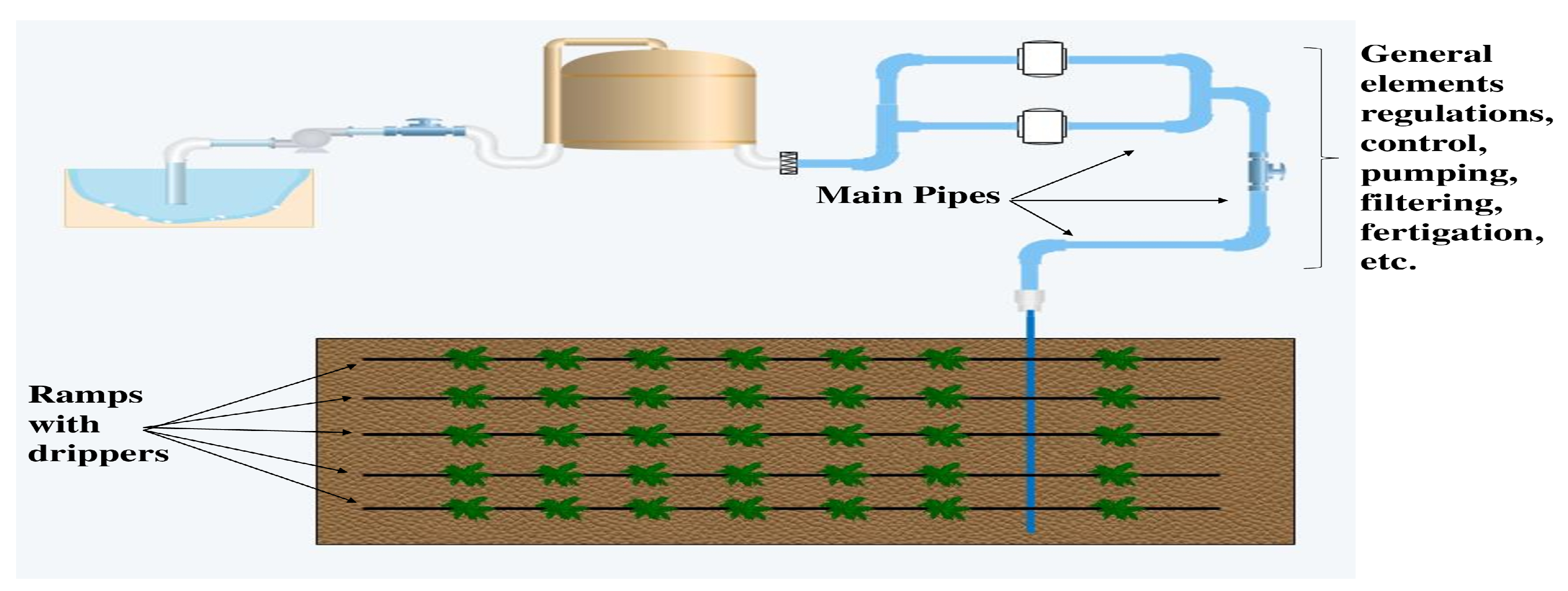
With the development of internet and engineering, soil and plant moisture sensors have been introduced to provide information on plant growth and to allow for the real-time operation of irrigation. Drip irrigation is a low-pressure, low-volume irrigation system [1,2,3]. Water is generally transported through polyethylene pipes and is applied directly to the root zone of plants. Selection of a suitable method for the crop, proper monitoring of the irrigation system and water supply, and appropriate application rates according to the growth stage of the crop, all of that are necessary for efficient irrigation systems. Important parameters to be measured for the automation of the irrigation system are soil moisture and temperature. The advantages of drip irrigation systems over overhead sprinkler systems include reduced water consumption, erosion, and runoff risk, as well as reduced weed growth. The installation of an efficient irrigation system begins with a proper design and the selection of pipes and transmitters of the appropriate size to ensure adequate water flow. The drip system used 50% less water and produced 50% less weeds and 75% less bio-masses than the overhead system [4]. The disadvantages of drip irrigation systems include: more time required for initial installation, higher initial costs, Risks of obstruction of emitters by suspended solid particles or the precipitation of chemical salts contained in the water, Salt accumulation on the soil surface, Rapid deterioration of pipes including drippers, Exposure of surface side pipes and drippers to animal damage, regular monitoring and maintenance to ensure adequate water supply. Scientists [5,6,7,8,9] are working to replace traditional agriculture with integrated and affordable systems to produce more crops and more income from the same soil. With proper follow-up in the field, the advantages of the drip system becoming more productive far outweigh its drawbacks. A good transfer of technology and a good knowledge tool in the hands of farmers would provide great added value to increase production at a low cost. Innovations can reduce the competitive demand for water and energy. For example, minimizing water consumption and energy consumption could be achieved by using drip irrigation in agriculture [10,11,12,13,14]. Similarly, the power of the installations (Figure 1) can limit water requirements for cooling by using smart monitoring system. Engineers and researchers must play a more active role in solving water use problems in urban and rural areas.
This work proposes an intelligent, dynamic, and automated monitoring system based on moisture and temperature sensor applied to irrigation systems for agricultural crops [15,16,17]. The system focuses on controlling the irrigation process automatically [18,19,20]. Automation is implemented by programming in VHSIC Hardware Description Language (VHDL) code on the field-programmable gate array (FPGA) board to display and measure humidity as a function of temperature to monitor soil moisture [21,22,23].
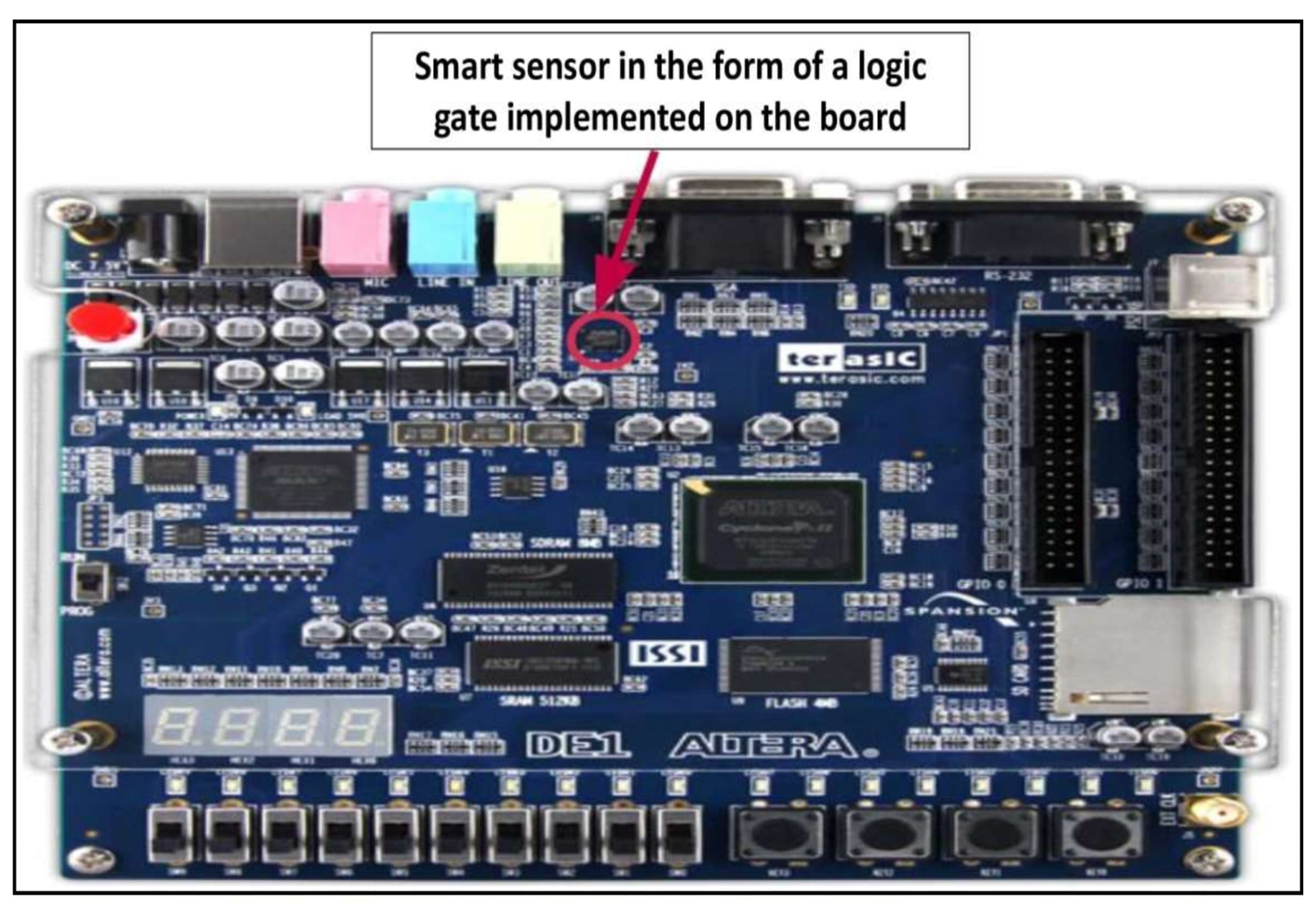
In this context, the FPGA (Field Programmable Gate Array) with its great integration and reconfiguration capabilities makes it a key component to develop prototypes quickly. FPGAs are two-dimensional arrays of logic blocks and flip-flops with an electrically programmable interconnect between the logic blocks. Specifically, the Altera DE1 Cyclone V board has become one of the most widely used FPGA development boards for sophisticated digital system development, design and implementation of a variety of FPGA projects. Using this smart sensor in the automation and regulation system of the drip irrigation process makes the monitoring easily at any time and anywhere, by any person. The smart monitoring system is in good condition and is incorporated with modern equipment and devices that can effectively withstand different environmental conditions without deteriorating. Thus, the intelligent irrigation system offers great flexibility for a practical irrigation process, and optimal solutions for water conservation with precision. This paper is organized as follows: In Section 2, materials and methods. The main results are summarized in Section 3. These two sections have concretized the primary objective that ultimately leads to the implementation of this smart monitoring system.
2. Materials and Methods
Conventional irrigation methods such as sprinkler irrigation, and flood-type feeding systems usually wet the soil and the lower leaves and stems of plants. All of the soil is saturated and often remains wet long afterward irrigation is complete. This condition favours fungal infections and leaf mould. Flooding methods consume large amounts of water and the area between crops remains dry and only receives moisture through accidental rains. On the contrary, drip or runoff irrigation is a modern irrigation technique that slowly applies small amounts of water to part of the plant root zone.
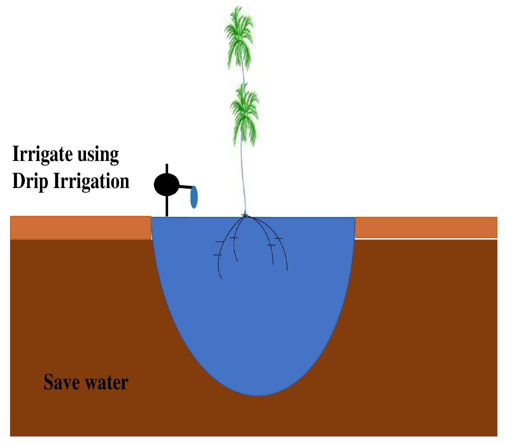
The drip irrigation method was invented by the Israelis in the 1970s [24]. Water is provided frequently, often daily, to maintain good soil moisture levels. Figure 2 shows the proliferation of water stress in a plant with good water use methods.
The percentage of the area wetted and the volume of soil wetted depend on the properties of the soil, its initial moisture content, the volume of water applied, and the flow rate of the emitter. In free-flowing or clay soils, the lateral movement of water below the soil surface is more pronounced than in sandy soils. The vertical bulb of wetted soil in sandy soil resembles a core. In free soil, the dimensions of the wet bulb are similar in depth and diameter. In heavy soils, however, the horizontal zone of moisture extension is larger than its depth.
The simulations and validation are there for reasons to study the possibility of monitoring the irrigation by an integrated system that will be designed later, the vhdl code of this monitoring system develop capable of verifying the requirements which displays the evolution of the amount of water in the air at 100% relative humidity according to temperatures.
2.1. Features of the Smart Monitoring System
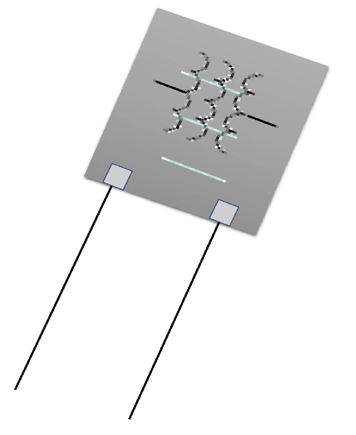
A humidity sensor (or hygrometer) (Figure 3), measures both the humidity and temperature of the air. Relative humidity is defined as the ratio of the humidity of the air to the greatest amount of moisture at a given air temperature. Relative humidity becomes an important factor in the search for comfort.
The characteristics and limits of the smart sensor:
- Temperature: 0–40 ℃ (32.0–104 F)
- Response time: <30 s
- Temperature measurement uncertainty: ±1
- Automatic temperature compensation: 0 C∼40 C
- Operating temperature: −20 C∼40 C
- Working humidity: ≤85% RH
Although the smart sensor is the central device of the drip irrigation system in this paper, it is composed of several other elements. These must be compatible with each other and adapted to the requirements of the crops and the characteristics of the irrigated plot. These elements fall into seven main categories:
- A water source: a pumping system from a surface or groundwater source, or in connection with a public, commercial or cooperative supply system,
- A distribution system: main, branch and collector (feeder) pipes,
- Lateral booms,
- Control accessories: valves, water meters, pressure and flow regulators, automatic devices, backflow preventers, vacuum valves, air release valves, etc,
- Filtering system,
- Chemical injection equipment: plant nutrients and water treatment agents,
- Drippers.
2.2. The Original Design Flow for the Implementation of This Smart Monitoring System
The rapid evolution of manufacturing techniques and technologies has led to the birth of increasingly powerful and complex FPGAs. The latest generation of FPGAs include embedded processors, ultra-fast communication links, and many other features. They are also increasingly dense (up to 1 billion equivalent logic gates) and faster (up to 500 MHz). All this allows the realization of very complex and high performance systems. Moreover, the potential of static and dynamic reconfigurability allows to take into account the evolution of standards and thus to modify the internal architecture while the board and the rest of the components remain fixed. FPGAs have become one of today’s most powerful technologies for developing systems that require real-time operation. FPGAs offer additional flexibility: they can be used in tighter time-to-market.
The increasing density of FPGAs allows the rapid prototyping of highly complex digital circuits. Also, it is possible to quickly test the validity of new architectural concepts: the complete implementation of a microsystem on FPGA circuits is now within our reach. In this context, we propose an original design flow for the fast implementation of this smart monitoring system.
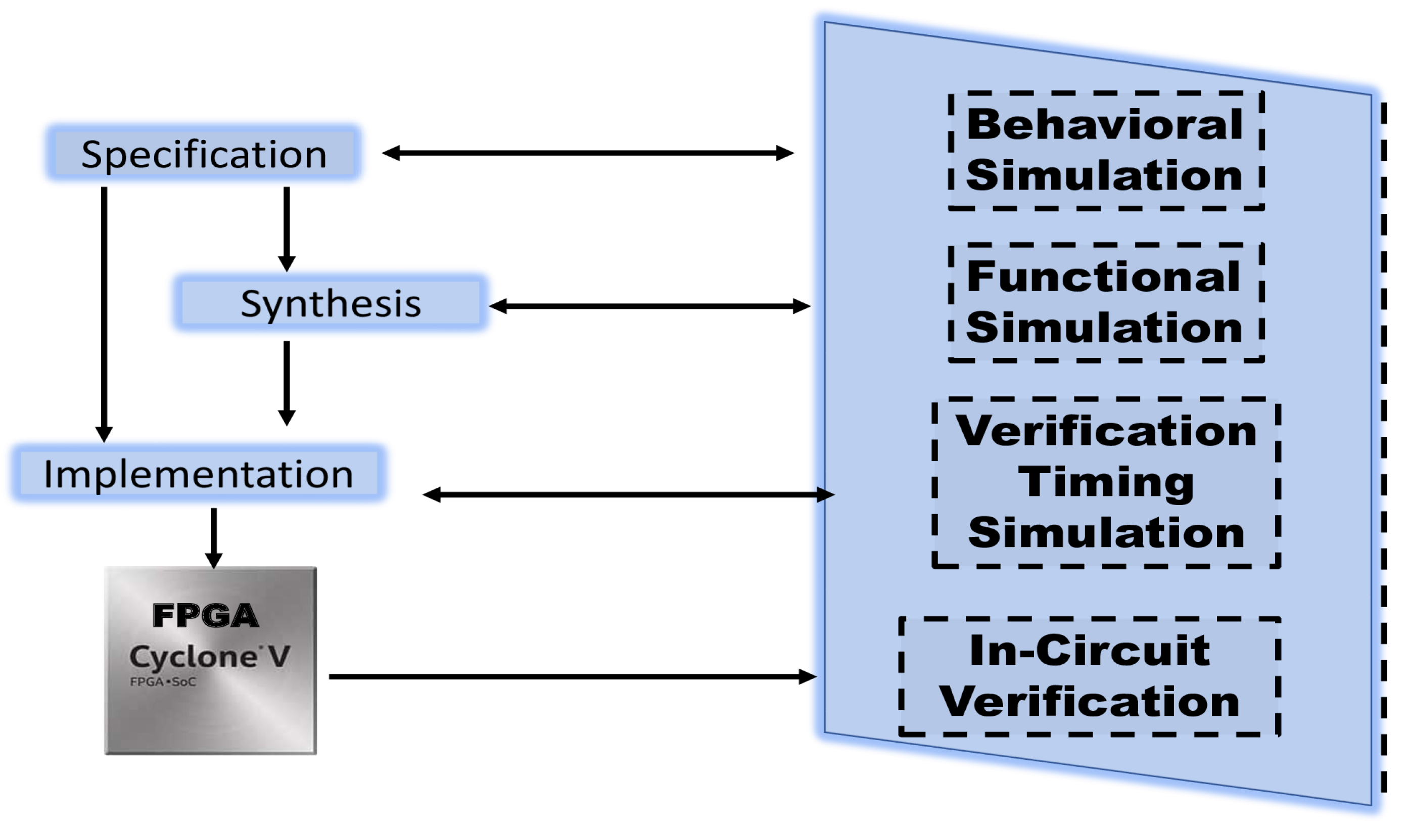
The design flow of an application on FPGA is usually realized in several steps. First of all, the algorithmic specifications allow to define the architecture by an Algorithm Architecture Adequacy approach. This architecture is then described with an HDL language. We can then simulate the system, and modify it if necessary. Then come the synthesis and placement routing phases, which consist in determining which elements will actually be used in the FPGA and how they will be connected to each other, where they will be placed in the component, etc. Each phase requires a verification of the global correctness and the timings, and if necessary modifications. Hardware description languages such as VHDL or Verilog, usually used for FPGA development, are concurrent in nature. Programming in VHDL (used in the specifications of our smart monitoring system) implies a good knowledge not only of the algorithm but also of the FPGA architecture and the compiler used. Therefore these steps mentioned above could not be managed without computer-aided design tools and electronic design automation (EDA), it plays a central role for industry, economy and society. Recent developments in EDA have focused mainly on improving the consistency of the integrated circuit design flow.
To recap, the typical flow of an FPGA consists of five main phases illustrated in Figure 4, which are behavioral simulation, functional simulation, static analysis, post-layout timing simulation and in-circuit verification.
A prototype has been built and the embedded monitoring system has been simulated and validated on Cadence tools, as well as the implementation on the Altera Cyclone V DE1 FPGA board. If we wish, we can then, in a future work, proceed to the Design Rule checking (DRC), Layout Versus Schematics (LVS), and the generation of the necessary masks from the Graphic Design System (GDSII) file, then send it to the foundry for the production of this intelligent sensor on a small chip and just after its manufacture, we test it on a real field, on plants irrigated by the drip system, and why not to expose it on a next article if everything is correct.
2.3. Irrigation System Performance Efficiency
In this section we would like to expose several important theories which ensure the understanding what happens to applied irrigation water, a clear distinction is made between water that is consumed and water that is used beneficially. Once that is known, there are several ratios, terms or equations that can be used to describe irrigation performance and the mathematical explanation of Irrigation system performance efficiency. These equations are not used in the results section.
Irrigation water may be distributed from a storage tank and transported to the field or farm through a canal system, it may be pumped from a tank on the farm and transported through a system of agricultural canals, or it may be pumped from a single well or a series of wells through agricultural canals. To regulate flow, manage water that is diverted, provide short-term storage, and meet farm demand, irrigation districts often include small to medium-sized reservoirs. [25,26,27]. Some on-farm systems use tanks for storage and flows from multiple wells.
2.3.1. Water Conveyance Efficiency
Transport efficiency is generally defined as the ratio of water reaching a farm or field [28,29] and is defined as follows:
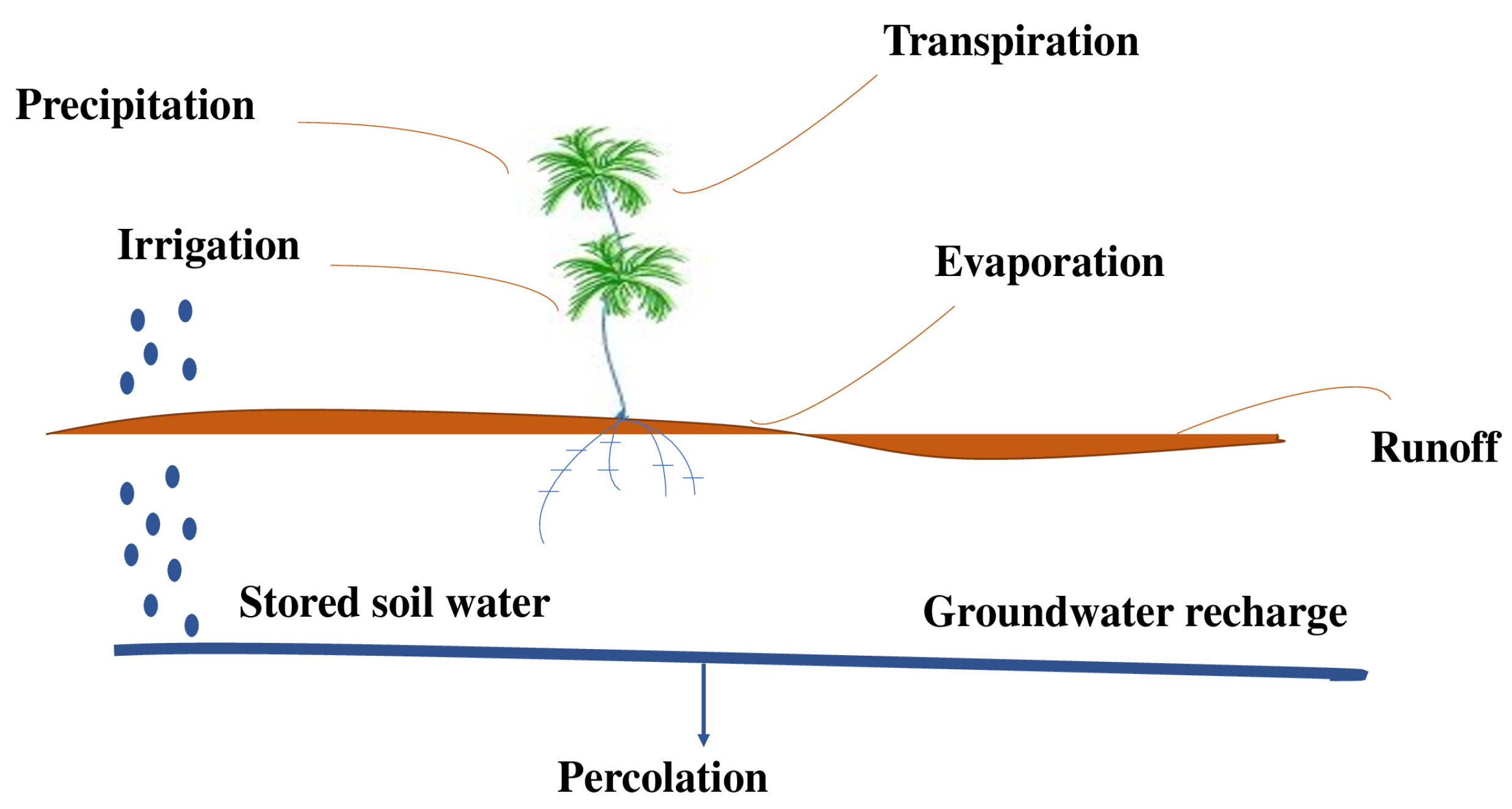
where is the transport efficiency (%), is the volume of water reaching the farm or field (), and is the volume of water diverted () from the source. also applies to segments of canals or pipelines, where water losses include infiltration into canals or leaks in pipes. The overall can be calculated as the product of the efficiency of the individual components, , where i represents the segment number. Transport losses include any channel spills (operational or accidental), seepage from tanks, and the evaporation that could result from management, as well as losses resulting from the physical configuration or the condition of the irrigation system. Generally, transportation losses are much lower for closed pipelines or pipelines [10]. Compared to uncoated or coated channels. Even the transport efficiency of coated channels may decrease over the years due to deterioration of materials or poor maintenance. Figure 5 shows an illustration of the different components of water transport required to characterize irrigation efficiency.
2.3.2. Application Efficiency
To meet the crop’s water requirements relative to the water applied in the field, it is often found that Application efficiency is related to the effective storage of water in the root zone. It can be defined for individual irrigations or parts of irrigations (sets of irrigations). Application efficiency and fertility includes any application loss due to evaporation or seepage from surface water channels or grooves, possible leakage from sprinklers or drip lines, percolation below the root zone, drift from sprinklers, evaporation of droplets into the air, or field runoff. Application efficiency is defined as:
where E is the application efficiency (%), V is the irrigation required for the crop (), and is the water supplied to the field or farm (). The root zone may not need to be completely filled in, especially if part of the root zone has retained water capacity is needed to store possible or probable rainfall. Often the is characterized as the volume of water stored in the root zone from the irrigation application. Some irrigation may be applied for reasons other than meeting crop water requirements (germination, frost control, crop cooling, chemigation, fertigation, or weed germination). Crop need is often based on “beneficial water requirements”. The runoff water needed to achieve good field uniformity can be recovered in a “tail water pit” and recirculated with current irrigation or used for subsequent irrigation, and should be adjusted to account for the “net” recovered tail water. Efficiency values are generally site specific.
2.3.3. Seasonal Irrigation Efficiency
The seasonal irrigation efficiency is defined as:
where is the seasonal irrigation efficiency (%) and is the volume of water advantageously used by the crop (). is somewhat subjective [17,29], but it essentially comprises the required crop evapotranspiration (ETc) plus all leach water (Vl) for managing the salinity of the root zone crop.
2.3.4. Irrigation Water Use Efficiency (WUE)
The previous sections have addressed the technical aspects of irrigation efficiency. Irrigation efficiency is clearly influenced by the amount of water used in relation to the irrigation water applied to the crop and the uniformity of the applied water. These efficiency factors have an impact on irrigation costs, irrigation design, and most importantly in some cases, crop productivity. Water use efficiency (WUE) has been the most widely used parameter to describe the efficiency of irrigation in terms of crop yield. The previous discussion on WUE did not explicitly explain the response of crop yield to irrigation. Water use efficiency is influenced by the use of crop water (ET). The term for WUE to characterize the influence of irrigation on WUE is defined as:
where WUE is the efficiency of irrigation water use ( ), is the economic return (g ) for irrigation level i, is the dryland yield (g ) in fact, (crop yields without irrigation), is the evapotranspiration (mm) for irrigation level i, and is the evapotranspiration from the crops in arid zones (or ET without irrigation). If the objective is to compare irrigation and dryland production systems, then arid areas rather than non-irrigated areas must be used. If the objective is to compare irrigated diets with non-irrigated diets, then appropriate values for and should be used.
Often, in most semi-arid to arid areas, the can be zero. Irrigation efficiency is an important technical term that implies an understanding of soil science and agronomy to get the most out of irrigation. Improving the understanding of irrigation efficiency can enhance the beneficial use of limited and declining water resources needed to improve agricultural and food production of irrigated land-based crops. Thus, drip irrigation using monitoring system integrated drip irrigation in embedded systems is one of the most efficient techniques used to save water and farmer’s time and energy. The use of integrated technology, such as 65 nm Complementary Metal Oxide Semiconductor (CMOS), in farming practices would make farming easier and enable farmers to monitor crops. In the next section, we will validate our findings by a simulation and implementation on the FPGA board of our smart monitoring system that measures air humidity as a function of soil temperature.
3. Results
3.1. Simulation and Validation of the Smart Monitoring System with Modelsim
The simulation of a smart monitoring system for irrigation followed the development of the VHDL code. Using VHDL language that has been designed and optimized for the behavior of electronic components ranging from simple logic gates to the function that makes the design of this smart monitoring system (Figure 6).
Thus, its test bench took into consideration the fact that we were extracting the necessary measurements. This is why the transmission rate of the temperature information is the same for both parameters (temperature and humidity). Therefore, the information will be processed for 200 ns at each rising edge of the clock to allow the necessary time to calculate and execute the following information after compiling the two VHDL codes under the mentor graphics medelsim tool.
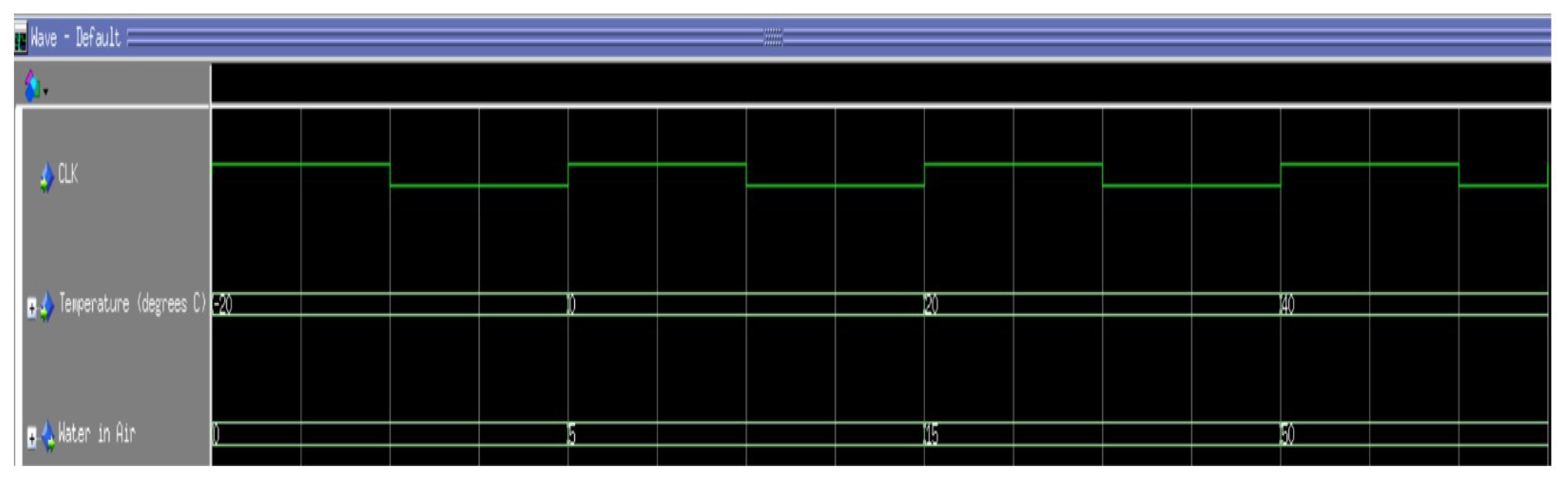
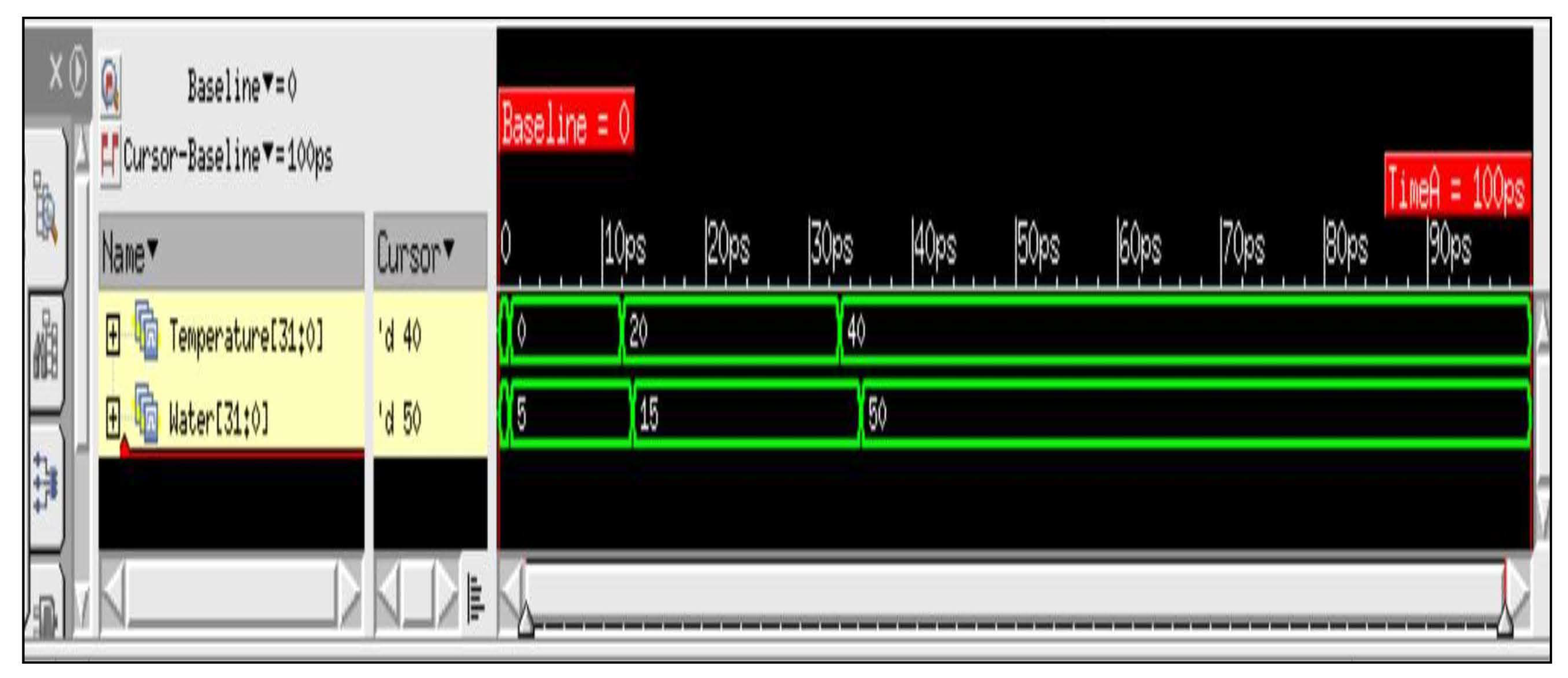
The Figure 7 shows the results of the simulation, meeting the initial specifications and the detection of temperature as a function of soil moisture.
As shown in Figure 7, the simulation signals explain the role of the smart sensor in providing temperature information as a function of water needed. The findings validate the VHDL code since it is the correct functioning of a smart sensor. In this paper, the new sensor was developed, simulated, and verified with a VHDL code using a test bench at the LIMA laboratory (Advanced Microsystems Engineering Laboratory).
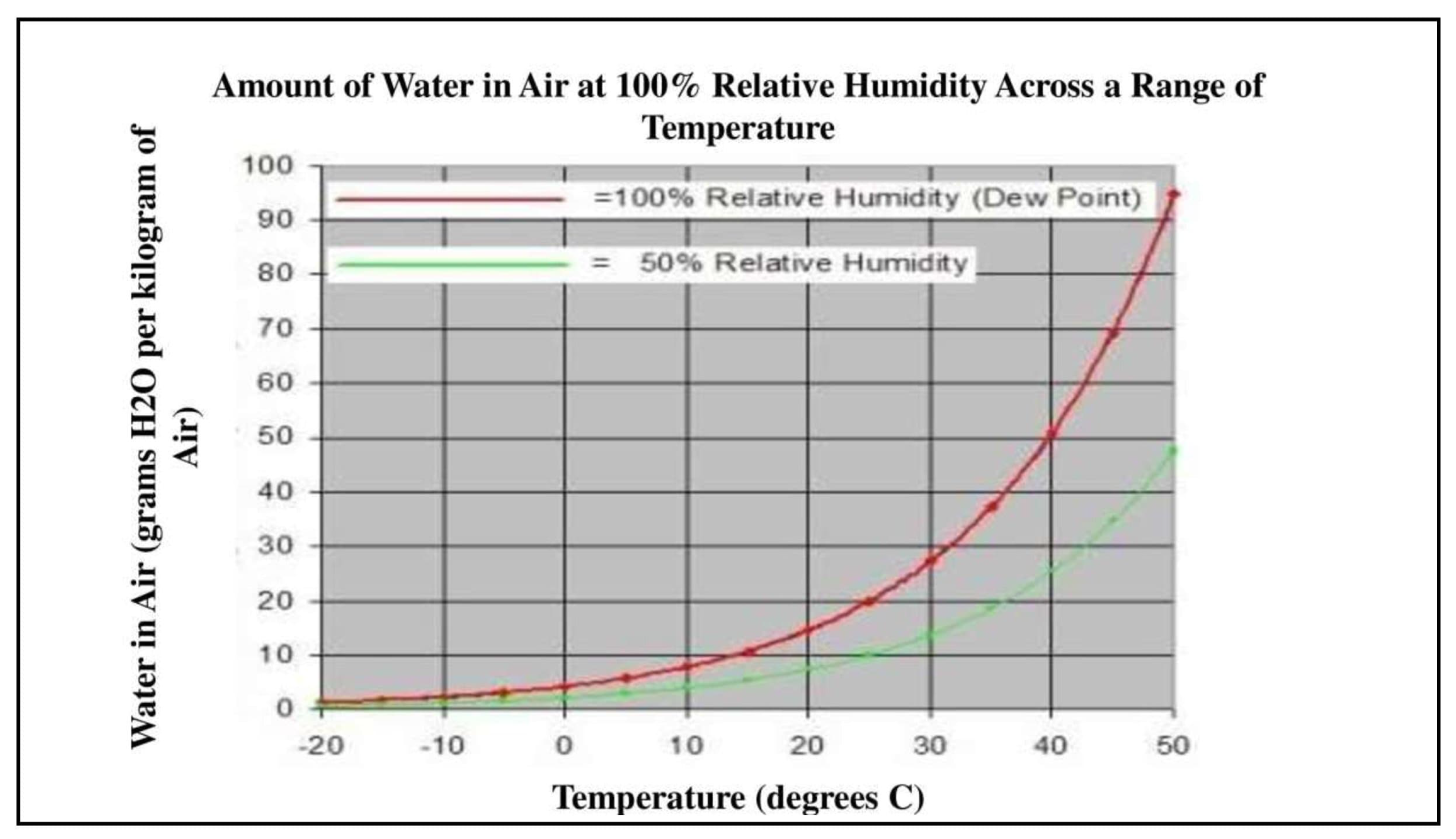
This result confirms the graph that is developed by [30], which shows that as the air temperature increases, the amount of water needed to saturate it increases exponentially. A few degrees of temperature increase have an increasingly important effect on the saturation point. Air that is saturated with water is at a relative humidity of 100%.
The importance of Figure 8 shows the shape related to the energy required to escape from the water surface and the energy distribution of the molecules in the water. As the water gets hotter, more molecules can escape.
3.2. FPGA Implementation and Results
The main objective of this section is the implementation and validation of theoretical results and simulation studies. As we can see in Figure 8, the air at 100% humidity is saturated with water. If a volume of water-saturated air is heated, the saturation level decreases and the air needs additional humidity to become saturated again (or less saturated if you are left-handed). Water-saturated air is at 100% relative humidity.
The percentage of relative humidity is the total water required for a volume of air divided by the amount of water that would be required to fully saturate that volume of air. During drying, it is important to understand the role of temperature and humidity and how they are related to each other to understand how to irrigate with our new smart sensor.
Validation of the Smart Monitoring System with Nclaunch
For the validation, the same simulations were repeated under the same conditions for the new smart monitoring system, this time with the nclaunch Cadence tool to validate the technological aspect to understand the degree of integration, the realization and manufacturing. After the insertion code has been developed using 65 nm technology and the results shown in Figure 8, the simulation results are presented in Figure 9.
The VHDL code will be put into the operation to facilitate the development of the architecture for their implementation in very large scale integrated (VLSI). This architecture will be modeled in high-level language, simulated to evaluate their performance, and implemented on an FPGA.
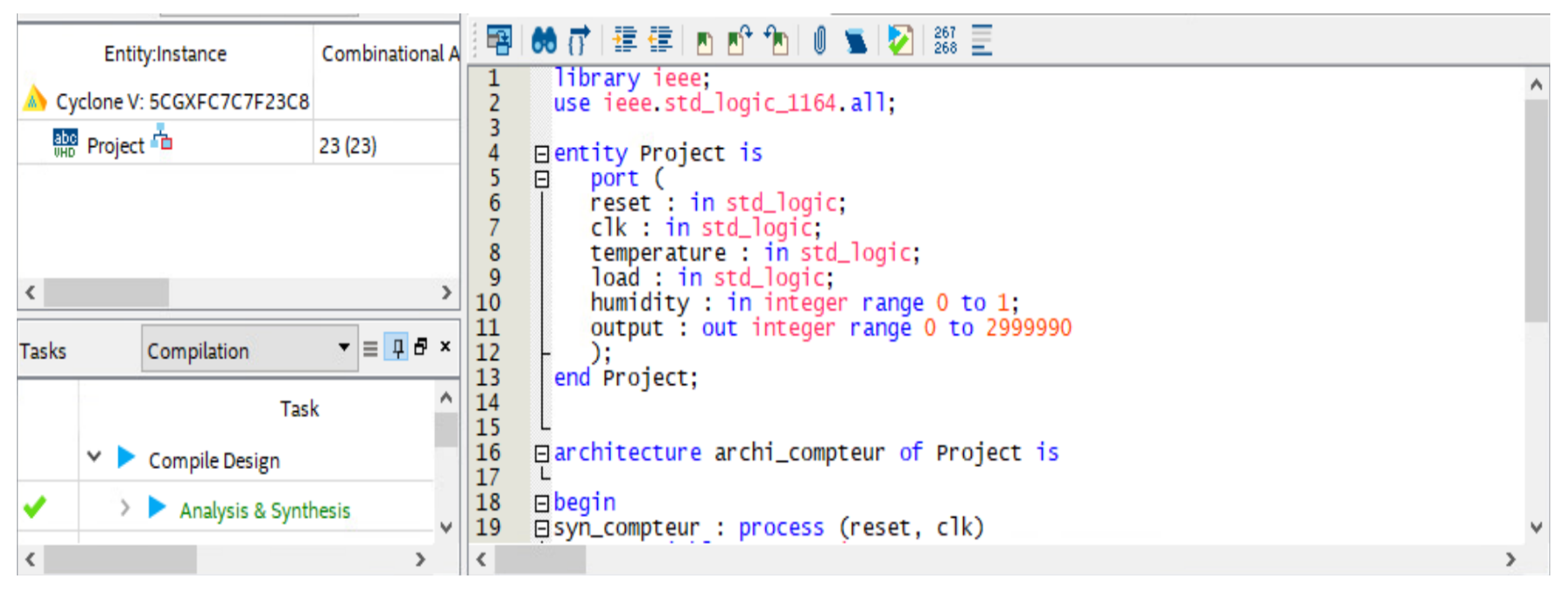
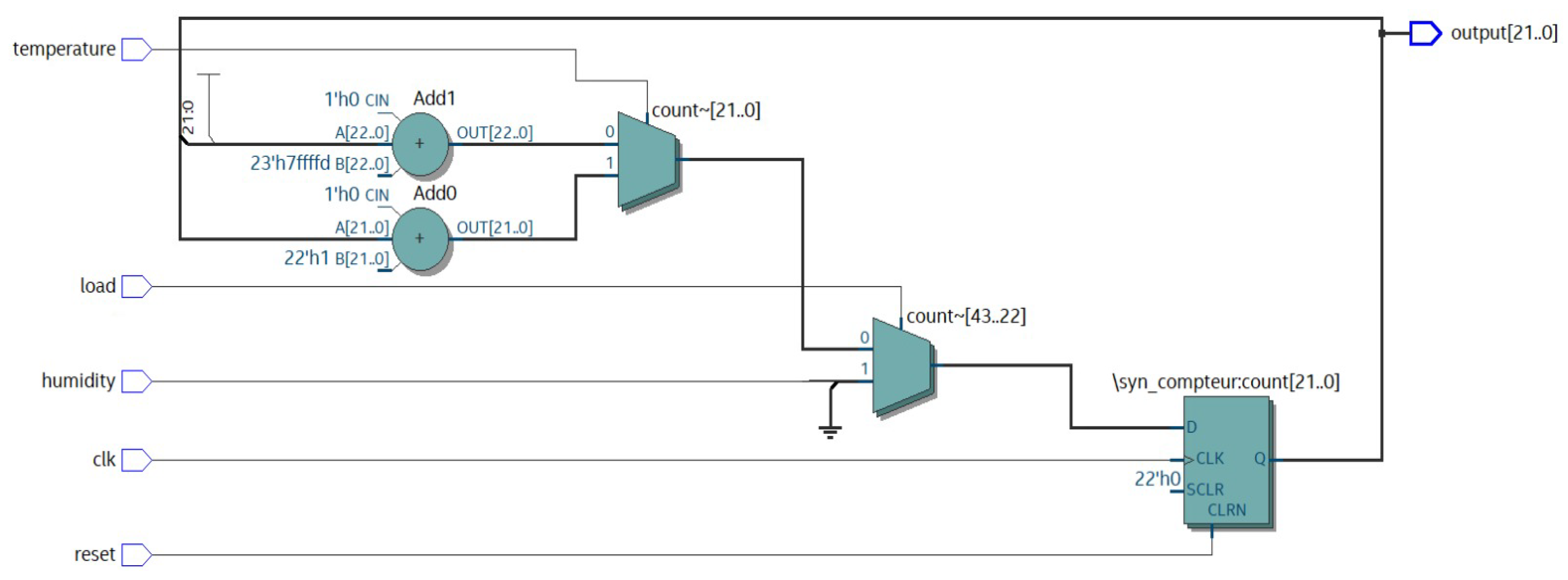
As we can see in Figure 9, the results of the simulation and validation of the smart sensor VHDL code developed with the modelsim tool perfectly match the results found in Figure 7. After validating our results with the nclaunch technology tool, now our next step is to verify that our smart sensor is technologically feasible and implementable on an FPGA board. We perform this experiment in the next part of this paper. The validation of the simulation results model is performed using Quartus Prime software, which allows us to simulate the sensor behavior in real time. After generating the two .vhd files (the primary file system and the ”test bench” file) with the ”system generator” the role of the Quartus Prime Navigator is used to synthesize the design and generate the Register Transfer Level (RTL) files as shown in Figure 10.
The structure of the smart sensor, after synthesis with Altera Quartus Prime, is shown in Figure 10.
FPGA is used to validate our simulations carried out with the nclaunch tool, we have chosen this card (Figure 11) by what able to visualize the different values of temperatures, with this technique we will be able to monitor the soil with a very sensitive thermal sensor to know when we can irrigate. The VHDL code used has been validated. Once compiled after pin assignment, the program is ready to be downloaded to the DE1 Cyclone V family and 5CSEMA5F31C6 board as a device. Figure 11 shows that the VHDL code is successfully downloaded to the board.
The synthesis and implementation results presented in this section were obtained with Altera’s Quartus II synthesis tool targeting a DE1 Altera Cyclone V FPGA. The functionality of the RTL implementation produced by our compiler has been validated by RTL simulation. (Figure 8) shows that the temperature at 20 °C corresponds to 15 at 100% relative humidity level. This method can be applied in any type of environment to obtain improved performance to control temperature and humidity levels.
4. Discussion
This paper illustrates the development potential of a moisture sensor for intelligent monitoring and irrigation decisions. The good results obtained allow to provide accurate maps of water quantities usable by farmers through irrigation.
The future work will be tracking using zonal maps, which can be focused on problem areas to reduce and avoid water waste using drip irrigation technology. Farmers could also transfer this data into their application equipment to take the necessary actions at the scale of variations in their fields.
Today, irrigation is a management of section openings and closings on half or the whole boom. In addition, from the perspective of avoiding water waste, the reduction of applied plant protection products is the key to sustainable agricultural management. This step requires a reactive and precise management to the problems detected moisture in the plots.
5. Conclusions
The main goal of this work was to develop an intelligent monitoring system to save water and avoid water waste using drip irrigation technology. In this technology, plant moisture and temperature were accurately monitored and controlled in real time on roots in the form of droplets. To accomplish this, a prototype was constructed and embedded monitoring system was simulated and validated on Cadence tools, as well as implementation on the FPGA DE1 Altera Cyclone V board, was be performed. To achieve FPGA implementation the use of the VHDL code and its test bench was necessary to describe the behavior of our smart sensor. Drip irrigation using a sensor integrated into embedded systems was one of the most practical techniques used to save farmers water, time, and energy. As presented in this paper, the use of embedded system and sensor such as in 65 nm CMOS technology in agricultural practices would facilitate agriculture and enable farmers to monitor crops. We have validated our monitoring system by simulating and implementing on the FPGA board our intelligent sensor that measures air humidity as a function of soil temperature.
Author Contributions
A.O. developed a first version of the proposed system and wrote a first version of the paper, A.Z.B. completed the work, improved the system and drove deep revision of the paper to bring it in its present form, E.K. advised the two first authors in all steps of the work, from early conceptualization, paper writing and revising to get it in its present form and he also manages the project that funds this work, and finally A.L. is a senior author, system modeling specialist, who supervised all steps of the work, from conceptualization to paper writing and revision. All authors have read and agreed to the published version of the manuscript.
Funding
This research received no external funding.
Institutional Review Board Statement
Not applicable.
Informed Consent Statement
Not applicable.
Data Availability Statement
Not applicable.
Conflicts of Interest
TThe authors declare no conflict of interest.
References
- Goumopoulos, C.; O’Flynn, B.; Kameas, A. Automated zone-specific irrigation with wireless sensor/actuator network and adaptable decision support. Comput. Electron. Agric. 2014, 105, 20–33. [Google Scholar] [CrossRef]
- Miranda, F.; Yoder, R.; Wilkerson, J.; Odhiambo, L. An autonomous controller for site-specific management of fixed irrigation systems. Comput. Electron. Agric. 2005, 48, 183–197. [Google Scholar] [CrossRef]
- Patil, P.S.; Alai, S.R.; Malpure, A.C.; Patil, P.L. An intelligent and automated drip irrigation system using sensors network control system. Int. J. Innov. Res. Comput. Commun. Eng. 2014, 2, 7557–7559. [Google Scholar]
- Carol, M.; Martin Nicholson, M.S. Efficiency of Drip and Overhead Irrigation Systems. Available online: https://agsyst.wsu.edu/IrrigationSystems.html (accessed on 10 September 2021).
- Gutiérrez, J.; Villa-Medina, J.F.; Nieto-Garibay, A.; Porta-Gándara, M.Á. Automated irrigation system using a wireless sensor network and GPRS module. IEEE Trans. Instrum. Meas. 2013, 63, 166–176. [Google Scholar] [CrossRef]
- Jain, P.; Choudhury, S.B.; Bhatt, P.; Sarangi, S.; Pappula, S. Maximising Value of Frugal Soil Moisture Sensors for Precision Agriculture Applications. In Proceedings of the 2020 IEEE/ITU International Conference on Artificial Intelligence for Good (AI4G), Geneva, Switzerland, 21–23 September 2020; IEEE: New York, NY, USA; pp. 63–70. [Google Scholar]
- Kukal, M.S.; Irmak, S.; Sharma, K. Development and application of a performance and operational feasibility guide to facilitate adoption of soil moisture sensors. Sustainability 2020, 12, 321. [Google Scholar] [CrossRef] [Green Version]
- Chauhan, N.; Parmar, U.; Mehra, E.V. Wireless Automatic Irrigation System for Sandy Loam Soil. Available online: https://thepharmajournal.com (accessed on 12 April 2020).
- Tingey-Holyoak, J.; Pisaniello, J.D.; Buss, P.; Wiersma, B. Cost-Informed Water Decision-Making Technology for Smarter Farming. In Proceedings of the International Conference on Intelligent Human Systems Integration, Modena, Italy, 19–21 February 2020; Springer: Berlin/Heidelberg, Germany, 2020; pp. 404–408. [Google Scholar]
- Velmurugan, S. An IOT based Smart Irrigation System using Soil Moisture and Weather Prediction. 2020. Available online: https://papers.ssrn.com/sol3/papers.cfm (accessed on 2 May 2020).
- Gu, Z.; Qi, Z.; Burghate, R.; Yuan, S.; Jiao, X.; Xu, J. Irrigation scheduling approaches and applications: A review. J. Irrig. Drain. Eng. 2020, 146, 04020007. [Google Scholar] [CrossRef]
- Abioye, E.A.; Abidin, M.S.Z.; Mahmud, M.S.A.; Buyamin, S.; Ishak, M.H.I.; Abd Rahman, M.K.I.; Otuoze, A.O.; Onotu, P.; Ramli, M.S.A. A review on monitoring and advanced control strategies for precision irrigation. Comput. Electron. Agric. 2020, 173, 105441. [Google Scholar] [CrossRef]
- Sinwar, D.; Dhaka, V.S.; Sharma, M.K.; Rani, G. AI-based yield prediction and smart irrigation. In Internet of Things and Analytics for Agriculture, Volume 2; Springer: Berlin/Heidelberg, Germany, 2020; pp. 155–180. [Google Scholar]
- Kalaivani, K.; Vidhya, V.; Veerammal, V. Smart irrigation system with iot monitoring and notification in indian agriculture. J. Crit. Rev. 2020, 7, 4055–4061. [Google Scholar]
- Oukaira, A.; Ettahri, O.; Lakhssassi, A. Modeling and FPGA implementation of a thermal peak detection unit for complex system design. IJACSA Int. J. Adv. Comput. Sci. Appl. 2017, 8, 307–312. [Google Scholar] [CrossRef] [Green Version]
- Oukaira, A.; Mellal, I.; Ettahri, O.; Kengne, E.; Lakhssassi, A. Thermal management and monitoring based on embedded ring oscillator network sensors for complex system design. Int. J. Comput. Eng. Inf. Technol. 2017, 9, 127. [Google Scholar]
- Oukaira, A.; Pal, N.; Ettahri, O.; Kengne, E.; Lakhssassi, A. Simulation and FPGA implementation of thermal convection equation for complex system design. IREA Int. J. Eng. Appl. 2016, 2, 307–312. [Google Scholar]
- Lagos, M.; Serna, J.L.; Muñoz, J.F.; Suárez, F. Challenges in determining soil moisture and evaporation fluxes using distributed temperature sensing methods. J. Environ. Manag. 2020, 261, 11. [Google Scholar] [CrossRef] [PubMed]
- Morales Santos, A.; Nolz, R. Assessing canopy temperature-based water stress indices for soybeans under subhumid conditions. In Proceedings of the EGU General Assembly Conference Abstracts, Vienna, Austria, 3–8 May 2020; p. 16325. [Google Scholar]
- Izolan, P.L.R.; Rossi, F.D.; Hohemberger, R.; Konzen, M.P.; da Cunha Rodrigues, G.; Saquette, L.R.; Temp, D.C.; Lorenzon, A.F.; Luizelli, M.C. Low-Cost Fog Computing Platform for Soil Moisture Management. In Proceedings of the 2020 International Conference on Information Networking (ICOIN), Barcelona, Spain, 7–10 January 2020; IEEE: New York, NY, USA, 2020; pp. 499–504. [Google Scholar]
- Liu, Z.; Xia, Z.; Chen, F.; Hu, Y.; Wen, Y.; Liu, J.; Liu, H.; Liu, L. Soil Moisture Index Model for Retrieving Soil Moisture in Semiarid Regions of China. IEEE J. Sel. Top. Appl. Earth Obs. Remote Sens. 2020, 13, 5929–5937. [Google Scholar] [CrossRef]
- Bidgoli, R.D.; Koohbanani, H.; Keshavarzi, A.; Kumar, V. Measurement and zonation of soil surface moisture in arid and semi-arid regions using Landsat 8 images. Arab. J. Geosci. 2020, 13, 1–10. [Google Scholar] [CrossRef]
- Zhang, P.; Sun, W.; Xiao, P.; Yang, C. The process of moisture and temperature change of soil profile in Pisha sandstone area. In IOP Conference Series: Earth and Environmental Science; IOP Publishing: Bristol, UK, 2020; Volume 526, p. 012017. [Google Scholar]
- Galande, S.; Agrawal, G. Embedded controlled drip irrigation system. Int. J. Emerg. Trends Technol. Comput. Sci. IJETTCS 2013, 2, 37–41. [Google Scholar]
- Wang, W.; Dong, L.; Ma, C.; Wei, L.; Xu, F.; Feng, J. Experimental Investigation of Ground Radiation on Dielectric and Brightness Temperature of Soil Moisture and Soil Salinity. Sensors 2020, 20, 2806. [Google Scholar] [CrossRef] [PubMed]
- Baskar, J.; Usha, A.; Nagamani, C.; Mani, M.; Reddy, A.C.S. Automatic Irrigation System using Soil Moisture Sensor and Temperature Sensor with Arduino. Available online: http://jorstem.com/docs/vol6issue3/1.pdf (accessed on 4 December 2020).
- Basurto-Lozada, D.; Hillier, A.; Medina, D.; Pulido, D.; Karaman, S.; Salas, J. Dynamics of soil surface temperature with unmanned aerial systems. Pattern Recognit. Lett. 2020, 138, 68–74. [Google Scholar] [CrossRef]
- Ikeda, N.; Shigeta, R.; Shiomi, J.; Kawahara, Y. Soil-Monitoring Sensor Powered by Temperature Difference between Air and Shallow Underground Soil. Proc. ACM Interact. Mob. Wearable Ubiquitous Technol. 2020, 4, 1–22. [Google Scholar] [CrossRef] [Green Version]
- Aytekin, M.; Gökbulak, F. Effect of coppice forest clearance on soil moisture, temperature and certain selected soil characteristics. Forestist 2020, 70, 116–121. [Google Scholar] [CrossRef]
- Fuchs, J. Drying—The Effect of Temperature on Relative Humidity. 2013. Available online: https://techblog.ctgclean.com/2013/05/drying-the-effect-of-temperature-on-relative-humidity/ (accessed on 2 May 2020).
Figure 1.
Typical drip system layout.

Figure 2.
The proliferation of water stress in the plant.

Figure 3.
Air moisture monitoring system.

Figure 4.
Typical FPGA design flow.

Figure 5.
Illustration of the various water transport components needed to characterize irrigation efficiency.
Figure 5.
Illustration of the various water transport components needed to characterize irrigation efficiency.

Figure 6.
VHDL pseudo-code describing the logic gates of the smart sensor.

Figure 7.
Results of the simulation of the intelligent monitoring system.

Figure 8.
The amount of water in air at 100% relative humidity across a range of temperature.

Figure 9.
The results of the verification of the Verilog code developed.

Figure 10.
Structure of the smart monitoring system in Quartus Prime tool.

Figure 11.
Validation of simulation and implementation of the smart monitoring system results on the liquid-crystal display (LCD) of DE1 Altera Cyclone V.
Figure 11.
Validation of simulation and implementation of the smart monitoring system results on the liquid-crystal display (LCD) of DE1 Altera Cyclone V.

Publisher’s Note: MDPI stays neutral with regard to jurisdictional claims in published maps and institutional affiliations. |
© 2021 by the authors. Licensee MDPI, Basel, Switzerland. This article is an open access article distributed under the terms and conditions of the Creative Commons Attribution (CC BY) license (https://creativecommons.org/licenses/by/4.0/).
Share and Cite
MDPI and ACS Style
Oukaira, A.; Benelhaouare, A.Z.; Kengne, E.; Lakhssassi, A. FPGA-Embedded Smart Monitoring System for Irrigation Decisions Based on Soil Moisture and Temperature Sensors. Agronomy 2021, 11, 1881. https://doi.org/10.3390/agronomy11091881
AMA Style
Oukaira A, Benelhaouare AZ, Kengne E, Lakhssassi A. FPGA-Embedded Smart Monitoring System for Irrigation Decisions Based on Soil Moisture and Temperature Sensors. Agronomy. 2021; 11(9):1881. https://doi.org/10.3390/agronomy11091881
Chicago/Turabian StyleOukaira, Aziz, Amrou Zyad Benelhaouare, Emmanuel Kengne, and Ahmed Lakhssassi. 2021. "FPGA-Embedded Smart Monitoring System for Irrigation Decisions Based on Soil Moisture and Temperature Sensors" Agronomy 11, no. 9: 1881. https://doi.org/10.3390/agronomy11091881
Note that from the first issue of 2016, this journal uses article numbers instead of page numbers. See further details here.