Selective Laser Melting of Aluminum and Titanium Matrix Composites: Recent Progress and Potential Applications in the Aerospace Industry


Abstract
:
1. Introduction
1.1. Basic Concepts
1.2. Why Additive Manufacturing (AM) for Aerospace Applications?
- Production of complex geometries: The design freedom combined with the control over the movement of heat source, spot size, material feeding rate, and even the direction of deposition all associated with the AM technology are among the factors providing fabrication of parts with complex geometries (e.g., lattice structures). Moreover, since most of the components utilized in the aerospace industry are intricate in geometry, the AM technology can provide an exceptional opportunity to decrease the assembly cost [18,19].
- Minimized tooling requirements/operations: The single-stage and near-net-shape nature of the AM technology eliminates the need for multi-stage tooling [18]. However, the relatively poor surface quality of the AM-fabricated components may require post processing operations to reduce the surface roughness, especially in applications which are highly sensitive to the surface quality (e.g., aerospace industry). Machining, surface remelting, shot peening, sand blasting, laser sock peening and electrochemical polishing are the most frequently used post-processing methods.
- Reduced time and cost: Due to the absence of expensive and dedicated tools such as molds and dies, AM technology provides exceptional technological opportunities for rapid and cost-effective fabrication of components in small volume production. Moreover, the lower buy-to-fly ratio of parts fabricated by AM compared to the conventional manufacturing processes significantly reduces the material waste and, consequently, the manufacturing cost [20,21].
- Controlled atmosphere: The protected atmosphere involved in PBF–AM processes (especially the vacuum environment in electron beam melting (EBM)) makes it possible to process highly reactive and expensive high-temperature metals, which are usually difficult to process using conventional manufacturing routes. Moreover, the control over the atmosphere enables fabricating components with minimized defect levels (i.e., gas porosities and inclusions), which are of crucial importance in aerospace applications [22,23].
- Flexibility in alloy design: AM technology can be rapidly utilized to explore the feasibility of using new materials for specific applications [24].
- Superior mechanical properties: The significantly high cooling rates associated with AM processes lead to substantially refined microstructures with improved hardness and strength compared to those fabricated through conventional manufacturing routes [25].
- Feasibility of fabricating functionally graded materials: The control over the process parameters as well as the material composition associated with some of the AM processes provides an outstanding opportunity to invent bimetals, multi-materials as well as functionally graded materials (FGMs) benefitting from the gradient change in composition and microstructure along the building direction [26].
- Customized design: The ability to use customized mixtures of powders in AM facilitates fabricating MMCs and functionally graded metal matrix composites with improved mechanical properties compared to the conventionally processed counterparts [27].
1.3. Requirements of Parts for Aerospace Applications
2. Selective Laser Melting for Fabricating MMCs
2.1. Background
2.2. Powders for SLM of MMCs
2.2.1. Methods
2.2.2. Requirements of an Ideal Composite Powder
3. Selection of Reinforcing Particles based on the Potential Applications
3.1. Carbonaceous Materials
3.1.1. Surface Quality
3.1.2. Densification Level
3.2. Ceramic Particles/Ceramic Precursors
3.2.1. Surface Quality
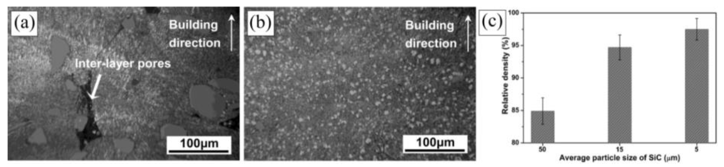
3.2.2. Densification Level
4. Mechanical Properties-Monolithic Alloys vs. Composites
4.1. Hardness
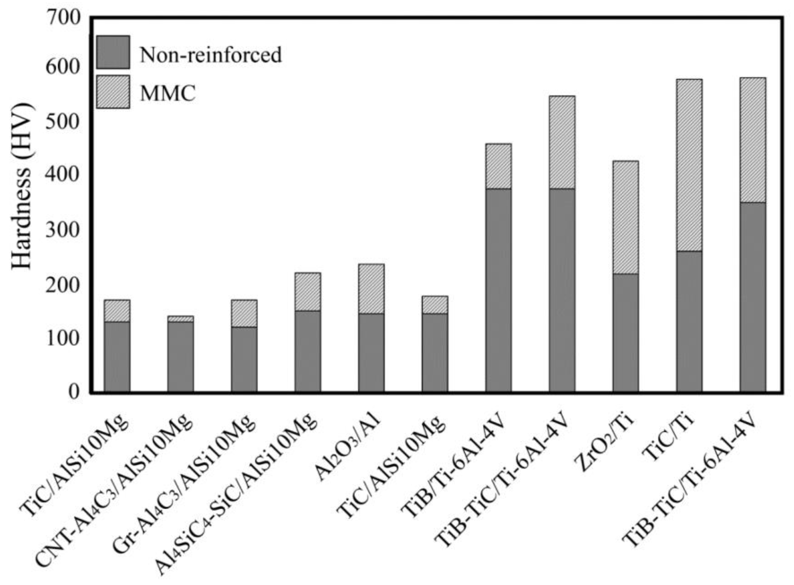
- When adding reinforcements to the system, a fraction of the metallic matrix is substituted by a harder constituent(s). Since the ceramic reinforcements typically have higher hardness than the metallic matrix, such a replacement leads to higher hardness based on the well-known mixture rule.
- The reinforcements incorporated into the metallic matrix, restrain its local micro-deformation by hindering the movement of dislocations [103]. Therefore, higher stresses are required for the deformation of the structure, resulting in higher hardness and strength.
- The solid reinforcing particles dispersed into the melt during laser processing act as heterogeneous nucleation sites for the matrix during its solidification [1,2]. This results in the grain refinement of the matrix and, consequently, the enhancement of hardness and strength [68,72]. The extent of such grain refinement is a major function of the size, volume fraction, and distribution pattern of reinforcing particles. The increase in volume fraction and decrease in size of reinforcing particles are regarded as the strategies providing the matrix with finer grains [89]. On the other hand, non-uniform matrix grain refinement induced by inhomogeneous distribution of reinforcements may degrade the mechanical properties of manufactured composites [48]. The composition of reinforcement is another factor that affects the hardness by influencing the formation of in-situ synthesized reinforcements and intermetallic phases during the process [104].
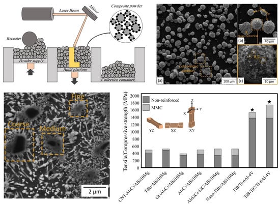
4.2. Tensile/Compressive Strength
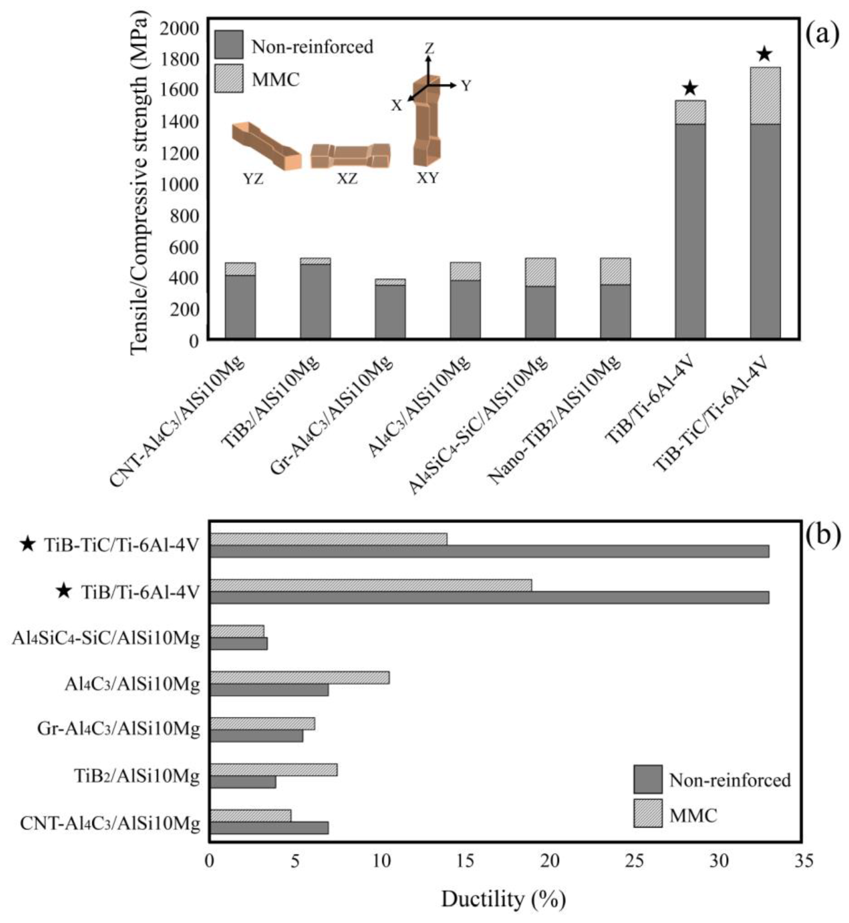
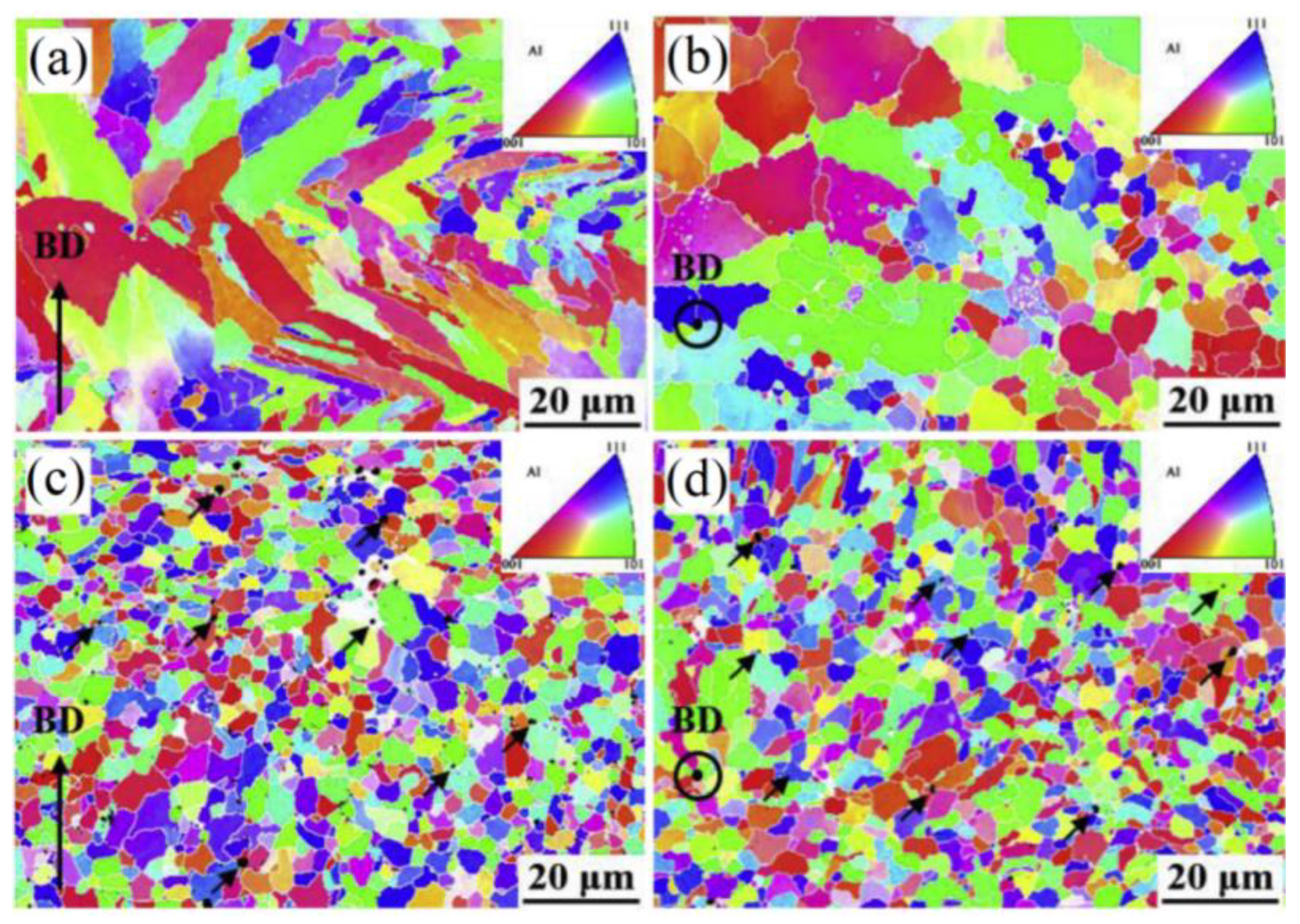
- Matrix grain refinement: The rapid cooling rates associated with the SLM process lead to significant grain refinement [95]. In the case of MMCs, the reinforcements can further refine the microstructure of the matrix by acting as preferential nucleation sites and grain growth inhibitors [2]. Due to the significant role of grain boundaries on the movement of dislocations, the increased fraction of grain boundaries obtained by grain refinement elevates the plastic deformation resistivity and consequently improves the strength of the material [111]. The reinforcing particles can also reduce the anisotropy in microstructure and mechanical properties [112]. As shown in Figure 14, the TiB2 reinforcing particles have remarkably reduced the anisotropy in the microstructure and texture of TiB2/AlSi10Mg composites. Compared to the relatively coarse columnar grain structure, strong <100> fiber orientation texture and the anisotropy in the mechanical properties for the AlSi10Mg alloy, the nano-TiB2 reinforced AMCs have shown equiaxed grains, no preferred crystallographic texture and significantly reduced anisotropy in mechanical properties [72].
- Solid solution strengthening: Due to the non-equilibrium nature of the process, the solution limit of alloying elements into the matrix can be extended, which favors a solid solution strengthening mechanism [113]. Compared to the substitutional alloying elements, the larger size misfit provided by interstitial alloying elements can generate significantly stronger obstacles for the movement of dislocations, leading to higher levels of solid solution strengthening [114]. Solid solution strengthening mechanisms have been reported in several research studies related to AM of MMCs [115,116,117,118,119,120].
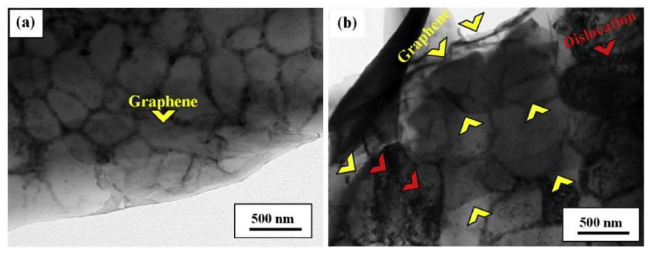
- Enhanced dislocation density: The dislocations generated in the SLM-processed parts have various resources, including multiple reheating thermal cycles caused by the layer-wise nature of this process as well as the difference between the CTE and elastic modulus of reinforcements and the matrix. Although the dislocations generated by repeated reheating cycles are evident in all AM processes, those induced by the mismatches in CTE and elastic modulus are features of composites [2]. To accommodate these mismatches, geometrically necessary dislocations are generated in the vicinity of the reinforcement/matrix interface (Figure 15a). The increase in the density of dislocations during the deformation of MMCs leads to higher work hardening rates and consequently results in improved strength (Figure 15b) [73].
4.3. Wear Properties
5. Conclusions
Author Contributions
Funding
Conflicts of Interest
References
- Fereiduni, E.; Yakout, M.; Elbestawi, M. Laser-Based Additive Manufacturing of Lightweight Metal Matrix Composites. In Additive Manufacturing of Emerging Materials; Springer Science and Business Media: Berlin/Heidelberg, Germany, 2018; pp. 55–109. [Google Scholar]
- Fereiduni, E.; Elbestawi, M. Process-Structure-Property Relationships in Additively Manufactured Metal Matrix Composites. In Additive Manufacturing of Emerging Materials; Springer Science and Business Media: Berlin/Heidelberg, Germany, 2018; pp. 111–177. [Google Scholar]
- Kaczmar, J.; Pietrzak, K.; Włosiński, W. The production and application of metal matrix composite materials. J. Mater. Process. Technol. 2000, 106, 58–67. [Google Scholar] [CrossRef]
- Miracle, D. Metal matrix composites—From science to technological significance. Compos. Sci. Technol. 2005, 65, 2526–2540. [Google Scholar] [CrossRef]
- Borgonovo, C.; Apelian, D. Manufacture of Aluminum Nanocomposites: A Critical Review. Mater. Sci. Forum 2011, 678, 1–22. [Google Scholar] [CrossRef]
- Chawla, K. Composite materials science and engineering. Composites 1989, 20, 286. [Google Scholar] [CrossRef]
- Jiang, L.; Li, Z.; Fan, G.; Cao, L.; Zhang, D. The use of flake powder metallurgy to produce carbon nanotube (CNT)/aluminum composites with a homogenous CNT distribution. Carbon 2012, 50, 1993–1998. [Google Scholar] [CrossRef]
- Fereiduni, E.; Movahedi, M.; Baghdadchi, A. Ultrahigh-strength friction stir spot welds of aluminium alloy obtained by Fe3O4 nanoparticles. Sci. Technol. Weld. Join. 2018, 23, 63–70. [Google Scholar] [CrossRef]
- Gupta, M.; Sharon, N.M.L. Magnesium, Magnesium Alloys, and Magnesium Composites; John Wiley & Sons: Hoboken, NJ, USA, 2011. [Google Scholar]
- Standard, A. F2792. 2012. Standard Terminology for Additive Manufacturing Technologies; ASTM International: West Conshohocken, PA, USA, 2012. [Google Scholar] [CrossRef]
- Frazier, W.E. Metal Additive Manufacturing: A Review. J. Mater. Eng. Perform. 2014, 23, 1917–1928. [Google Scholar] [CrossRef]
- ISO. ISO 17296-2:2015, Additive Manufacturing—General Principles—Part 2: Overview of Process Categories and Feedstock; ISO: Geneva, Switzerland, 2015. [Google Scholar]
- Shapiro, A.A.; Borgonia, J.P.; Chen, Q.N.; Dillon, R.P.; McEnerney, B.; Polit-Casillas, R.; Soloway, L. Additive Manufacturing for Aerospace Flight Applications. J. Spacecr. Rocket. 2016, 53, 952–959. [Google Scholar] [CrossRef]
- Torres, R.; Snoeij, P.; Geudtner, D.; Bibby, D.; Davidson, M.; Attema, E.; Potin, P.; Rommen, B.; Floury, N.; Brown, M.; et al. GMES Sentinel-1 mission. Remote. Sens. Environ. 2012, 120, 9–24. [Google Scholar] [CrossRef]
- Brandt, M.; Sun, S.; Leary, M.; Feih, S.; Elambasseril, J.; Liu, Q.C. High-Value SLM Aerospace Components: From Design to Manufacture. Adv. Mater. Res. 2013, 633, 135–147. [Google Scholar] [CrossRef]
- English, C.L.; Tewari, S.K.; Abbott, D.H. An Overview of Ni Base Additive Fabrication Technologies for Aerospace Applications. In Proceedings of the 7th International Symposium on Superalloy 718 and Derivatives, Pittsburgh, PA, USA, 10–13 October 2010. [Google Scholar]
- Seabra, M.; Azevedo, J.; Araújo, A.; Reis, L.; Pinto, E.; Alves, N.; Santos, R.; Mortágua, J.P. Selective laser melting (SLM) and topology optimization for lighter aerospace componentes. Procedia Struct. Integr. 2016, 1, 289–296. [Google Scholar] [CrossRef] [Green Version]
- Debroy, T.; Wei, H.; Zuback, J.; Mukherjee, T.; Elmer, J.; Milewski, J.; Beese, A.M.; Wilson-Heid, A.; De, A.; Zhang, W. Additive manufacturing of metallic components—Process, structure and properties. Prog. Mater. Sci. 2018, 92, 112–224. [Google Scholar] [CrossRef]
- Rosen, D.W. Computer-Aided Design for Additive Manufacturing of Cellular Structures. Comput. Des. Appl. 2007, 4, 585–594. [Google Scholar] [CrossRef]
- Attaran, M. The rise of 3-D printing: The advantages of additive manufacturing over traditional manufacturing. Bus. Horiz. 2017, 60, 677–688. [Google Scholar] [CrossRef]
- Herderick, E. Additive manufacturing of metals: A review. Mater. Sci. Technol. 2011, 2, 1413–1425. [Google Scholar]
- Fish, S.; Booth, J.C.; Kubiak, S.T.; Wroe, W.W.; Bryant, A.D.; Moser, D.R.; Beaman, J.J. Design and subsystem development of a high temperature selective laser sintering machine for enhanced process monitoring and control. Addit. Manuf. 2015, 5, 60–67. [Google Scholar] [CrossRef]
- Kanko, J.A.; Sibley, A.P.; Fraser, J.M. In Situ morphology-based defect detection of selective laser melting through inline coherent imaging. J. Mater. Process. Technol. 2016, 231, 488–500. [Google Scholar] [CrossRef]
- Pollock, T.M. Alloy design for aircraft engines. Nat. Mater. 2016, 15, 809–815. [Google Scholar] [CrossRef]
- Popovich, V.; Borisov, E.; Popovich, A.; Sufiiarov, V.; Masaylo, D.; Alzina, L. Functionally graded Inconel 718 processed by additive manufacturing: Crystallographic texture, anisotropy of microstructure and mechanical properties. Mater. Des. 2017, 114, 441–449. [Google Scholar] [CrossRef]
- Loh, G.H.; Eujin, P.; Harrison, D.; Monzón, M. An overview of functionally graded additive manufacturing. Addit. Manuf. 2018, 23, 34–44. [Google Scholar] [CrossRef] [Green Version]
- Gibson, I.; Rosen, D.W.; Stucker, B. Design for additive manufacturing. In Additive Manufacturing Technologies; Springer: Berlin/Heidelberg, Germany, 2010; pp. 299–332. [Google Scholar]
- Cozmei, C.; Caloian, F. Additive Manufacturing Flickering at the Beginning of Existence. Procedia Econ. Financ. 2012, 3, 457–462. [Google Scholar] [CrossRef] [Green Version]
- Baumers, M.; Tuck, C.; Hague, R.; Ashcroft, I.; Wildman, R. A comparative study of metallic additive manufacturing power consumption. In Proceedings of the Solid Freeform Fabrication Symposium, 2010; pp. 278–288. Available online: https://www.tib.eu/en/search/id/BLCP%3ACN077986101/A-Comparative-Study-of-Metallic-Additive-Manufacturing/ (accessed on 11 June 2020).
- Pal, S.; Lojen, G.; Kokol, V.; Drstvensek, I. Evolution of metallurgical properties of Ti-6Al-4V alloy fabricated in different energy densities in the Selective Laser Melting technique. J. Manuf. Process. 2018, 35, 538–546. [Google Scholar] [CrossRef]
- Kasperovich, G.; Haubrich, J.; Gussone, J.; Requena, G. Correlation between porosity and processing parameters in TiAl6V4 produced by selective laser melting. Mater. Des. 2016, 105, 160–170. [Google Scholar] [CrossRef] [Green Version]
- Kabir, M.R.; Richter, H. Modeling of Processing-Induced Pore Morphology in an Additively-Manufactured Ti-6Al-4V Alloy. Materials 2017, 10, 145. [Google Scholar] [CrossRef] [PubMed] [Green Version]
- Sing, S.L.; Wiria, F.E.; Yeong, W.Y. Selective laser melting of titanium alloy with 50 wt.% tantalum: Effect of laser process parameters on part quality. Int. J. Refract. Met. Hard Mater. 2018, 77, 120–127. [Google Scholar] [CrossRef]
- Strano, G.; Hao, L.; Everson, R.; Evans, K.E. Surface roughness analysis, modelling and prediction in selective laser melting. J. Mater. Process. Technol. 2013, 213, 589–597. [Google Scholar] [CrossRef]
- Greitemeier, D.; Donne, C.D.; Syassen, F.; Eufinger, J.; Melz, T. Effect of surface roughness on fatigue performance of additive manufactured Ti–6Al–4V. Mater. Sci. Technol. 2016, 32, 629–634. [Google Scholar] [CrossRef]
- Koli, D.K.; Agnihotri, G.; Purohit, R. Advanced Aluminium Matrix Composites: The Critical Need of Automotive and Aerospace Engineering Fields. Mater. Today Proc. 2015, 2, 3032–3041. [Google Scholar] [CrossRef]
- Carroll, B.E.; Palmer, T.A.; Beese, A.M. Anisotropic tensile behavior of Ti–6Al–4V components fabricated with directed energy deposition additive manufacturing. Acta Mater. 2015, 87, 309–320. [Google Scholar] [CrossRef]
- Thijs, L.; Sistiaga, M.L.M.; Wauthle, R.; Xie, Q.; Kruth, J.-P.; Van Humbeeck, J. Strong morphological and crystallographic texture and resulting yield strength anisotropy in selective laser melted tantalum. Acta Mater. 2013, 61, 4657–4668. [Google Scholar] [CrossRef] [Green Version]
- Wang, Z.; Palmer, T.A.; Beese, A.M. Effect of processing parameters on microstructure and tensile properties of austenitic stainless steel 304L made by directed energy deposition additive manufacturing. Acta Mater. 2016, 110, 226–235. [Google Scholar] [CrossRef] [Green Version]
- Kunze, K.; Etter, T.; Grässlin, J.; Shklover, V. Texture, anisotropy in microstructure and mechanical properties of IN738LC alloy processed by selective laser melting (SLM). Mater. Sci. Eng. A 2015, 620, 213–222. [Google Scholar] [CrossRef]
- Sterling, A.J.; Torries, B.; Shamsaei, N.; Thompson, S.M.; Seely, D.W. Fatigue behavior and failure mechanisms of direct laser deposited Ti–6Al–4V. Mater. Sci. Eng. A 2016, 655, 100–112. [Google Scholar] [CrossRef]
- Čapek, J.; Machová, M.; Fousová, M.; Kubásek, J.; Vojtěch, D.; Fojt, J.; Jablonska, E.; Lipov, J.; Ruml, T. Highly porous, low elastic modulus 316L stainless steel scaffold prepared by selective laser melting. Mater. Sci. Eng. C 2016, 69, 631–639. [Google Scholar] [CrossRef] [PubMed]
- Khaing, M.; Fuh, J.; Lu, L. Direct metal laser sintering for rapid tooling: Processing and characterisation of EOS parts. J. Mater. Process. Technol. 2001, 113, 269–272. [Google Scholar] [CrossRef]
- Mangano, C.; Chambrone, L.; Van Noort, R.; Miller, C.; Hatton, P.V.; Mangano, C. Direct Metal Laser Sintering Titanium Dental Implants: A Review of the Current Literature. Int. J. Biomater. 2014, 2014, 1–11. [Google Scholar] [CrossRef] [Green Version]
- Grünberger, T.; Domröse, R. Direct Metal Laser Sintering. Laser Tech. J. 2015, 12, 45–48. [Google Scholar] [CrossRef]
- Pohl, H.; Simchi, A.; Issa, M.; Dias, H.C. Thermal Stresses in Direct Metal Laser Sintering. In Proceedings of the 12th Solid Freeform Fabrication Symposium, Austin, TX, USA, 6–8 August 2001. [Google Scholar]
- De-Damborenea, J.; Arenas, M.; LaRosa, M.A.; Jardini, A.L.; Zavaglia, C.A.D.C.; Conde, A. Corrosion of Ti6Al4V pins produced by direct metal laser sintering. Appl. Surf. Sci. 2017, 393, 340–347. [Google Scholar] [CrossRef]
- Manfredi, D.; Calignano, F.; Krishnan, M.; Canali, R.; Paola, E.; Biamino, S.; Ugues, D.; Pavese, M.; Fino, P. Additive Manufacturing of Al Alloys and Aluminium Matrix Composites (AMCs). In Light Metal Alloys Applications; IntechOpen: London, UK, 2014. [Google Scholar]
- Zheng, L.; Zhang, M.; Chellali, R.; Dong, J. Investigations on the growing, cracking and spalling of oxides scales of powder metallurgy Rene95 nickel-based superalloy. Appl. Surf. Sci. 2011, 257, 9762–9767. [Google Scholar] [CrossRef]
- Chang, K.; Gu, D. Direct metal laser sintering synthesis of carbon nanotube reinforced Ti matrix composites: Densification, distribution characteristics and properties. J. Mater. Res. 2016, 31, 281–291. [Google Scholar] [CrossRef] [Green Version]
- Fereiduni, E.; Ghasemi, A.; Elbestawi, M. Selective laser melting of hybrid ex-situ/in-situ reinforced titanium matrix composites: Laser/powder interaction, reinforcement formation mechanism, and non-equilibrium microstructural evolutions. Mater. Des. 2019, 184, 108185. [Google Scholar] [CrossRef]
- Fereiduni, E.; Ghasemi, A.; Elbestawi, M. Characterization of Composite Powder Feedstock from Powder Bed Fusion Additive Manufacturing Perspective. Materials 2019, 12, 3673. [Google Scholar] [CrossRef] [Green Version]
- Zhou, S.Y.; Wang, Z.Y.; Su, Y.; Wang, H.; Liu, G.; Song, T.T.; Yan, M. Effects of Micron/Submicron TiC on Additively Manufactured AlSi10Mg: A Comprehensive Study from Computer Simulation to Mechanical and Microstructural Analysis. JOM J. Miner. Met. Mater. Soc. 2020, 1–12. [Google Scholar] [CrossRef]
- Yu, W.; Sing, S.; Chua, C.; Kuo, C.-N.; Tian, X. Particle-reinforced metal matrix nanocomposites fabricated by selective laser melting: A state of the art review. Prog. Mater. Sci. 2019, 104, 330–379. [Google Scholar] [CrossRef]
- Xi, L.; Wang, P.; Prashanth, K.; Li, H.; Prykhodko, H.; Scudino, S.; Gokuldoss, P.K. Effect of TiB2 particles on microstructure and crystallographic texture of Al-12Si fabricated by selective laser melting. J. Alloys Compd. 2019, 786, 551–556. [Google Scholar] [CrossRef]
- Li, X.; Ji, G.; Chen, Z.; Addad, A.; Wu, Y.; Wang, H.; Vleugels, J.; Van Humbeeck, J.; Kruth, J. Selective laser melting of nano-TiB 2 decorated AlSi10Mg alloy with high fracture strength and ductility. Acta Mater. 2017, 129, 183–193. [Google Scholar] [CrossRef]
- Zhou, W.; Sun, X.; Kikuchi, K.; Nomura, N.; Yoshimi, K.; Kawasaki, A. Carbon nanotubes as a unique agent to fabricate nanoceramic/metal composite powders for additive manufacturing. Mater. Des. 2018, 137, 276–285. [Google Scholar] [CrossRef]
- Li, M.; Fang, A.; Martinez-Franco, E.; Alvarado-Orozco, J.M.; Pei, Z.; Ma, C. Selective laser melting of metal matrix composites: Feedstock powder preparation by electroless plating. Mater. Lett. 2019, 247, 115–118. [Google Scholar] [CrossRef]
- Suryanarayana, C. Mechanical alloying and milling. Prog. Mater. Sci. 2001, 46, 1–184. [Google Scholar] [CrossRef]
- Cleary, P.W.; Sawley, M.L. DEM modelling of industrial granular flows: 3D case studies and the effect of particle shape on hopper discharge. Appl. Math. Model. 2002, 26, 89–111. [Google Scholar] [CrossRef]
- Karapatis, N.; Egger, G.; Gygax, P.; Glardon, R. Optimization of powder layer density in selective laser sintering. In Proceedings of the 10th Solid Freeform Fabrication Symposium (SFF), Austin, TX, USA, 9–11 August 1999. [Google Scholar]
- Cleary, P.W. The effect of particle shape on simple shear flows. Powder Technol. 2008, 179, 144–163. [Google Scholar] [CrossRef]
- Ghadiri, M.; Pasha, M.; Nan, W.; Hare, C.; Vivacqua, V.; Zafar, U.; Nezamabadi, S.; Lopez, A.; Pasha, M.; Nadimi, S. Cohesive Powder Flow: Trends and Challenges in Characterisation and Analysis. KONA Powder Part. J. 2020, 37, 3–18. [Google Scholar] [CrossRef] [Green Version]
- Gu, D.; Wang, H.; Dai, D. Laser Additive Manufacturing of Novel Aluminum Based Nanocomposite Parts: Tailored Forming of Multiple Materials. J. Manuf. Sci. Eng. 2015, 138, 021004. [Google Scholar] [CrossRef] [Green Version]
- Chen, M.; Li, X.; Ji, G.; Wu, Y.; Chen, Z.; Baekelant, W.; Vanmeensel, K.; Wang, H.; Kruth, J.-P. Novel Composite Powders with Uniform TiB2 Nano-Particle Distribution for 3D Printing. Appl. Sci. 2017, 7, 250. [Google Scholar] [CrossRef]
- Wang, P.; Gammer, C.; Brenne, F.; Niendorf, T.; Eckert, J.; Scudino, S. A heat treatable TiB2/Al-3.5 Cu-1.5 Mg-1Si composite fabricated by selective laser melting: Microstructure, heat treatment and mechanical properties. Compos. Part B Eng. 2018, 147, 162–168. [Google Scholar] [CrossRef]
- Lin, T.-C.; Cao, C.; Sokoluk, M.; Jiang, L.; Wang, X.; Schoenung, J.M.; Lavernia, E.J.; Li, X. Aluminum with dispersed nanoparticles by laser additive manufacturing. Nat. Commun. 2019, 10, 1–9. [Google Scholar] [CrossRef] [Green Version]
- Wang, M.; Song, B.; Wei, Q.; Shi, Y. Improved mechanical properties of AlSi7Mg/nano-SiCp composites fabricated by selective laser melting. J. Alloys Compd. 2019, 810, 151926. [Google Scholar] [CrossRef]
- Wu, L.; Zhao, Z.; Bai, P.; Zhao, W.; Li, Y.; Liang, M.; Liao, H.; Huo, P.; Li, J. Wear resistance of graphene nano-platelets (GNPs) reinforced AlSi10Mg matrix composite prepared by SLM. Appl. Surf. Sci. 2020, 503, 144156. [Google Scholar] [CrossRef]
- Jiang, L.; Liu, T.; Zhang, C.; Zhang, K.; Li, M.; Ma, T.; Liao, W. Preparation and mechanical properties of CNTs-AlSi10Mg composite fabricated via selective laser melting. Mater. Sci. Eng. A 2018, 734, 171–177. [Google Scholar] [CrossRef]
- Liao, H.; Zhu, H.; Xue, G.; Zeng, X. Alumina loss mechanism of Al2O3-AlSi10Mg composites during selective laser melting. J. Alloys Compd. 2019, 785, 286–295. [Google Scholar] [CrossRef]
- Xiao, Y.; Bian, Z.; Wu, Y.; Ji, G.; Li, Y.; Li, M.; Lian, Q.; Chen, Z.; Addad, A.; Wang, H. Effect of nano-TiB2 particles on the anisotropy in an AlSi10Mg alloy processed by selective laser melting. J. Alloys Compd. 2019, 798, 644–655. [Google Scholar] [CrossRef]
- Zhao, Z.; Bai, P.; Misra, R.; Dong, M.; Guan, R.; Li, Y.; Zhang, J.; Tan, L.; Gao, J.; Ding, T.; et al. AlSi10Mg alloy nanocomposites reinforced with aluminum-coated graphene: Selective laser melting, interfacial microstructure and property analysis. J. Alloys Compd. 2019, 792, 203–214. [Google Scholar] [CrossRef]
- Xue, G.; Ke, L.; Zhu, H.; Liao, H.; Zhu, J.; Zeng, X. Influence of processing parameters on selective laser melted SiCp/AlSi10Mg composites: Densification, microstructure and mechanical properties. Mater. Sci. Eng. A 2019, 764, 138155. [Google Scholar] [CrossRef]
- Xi, L.; Zhang, H.; Wang, P.; Li, H.; Gokuldoss, P.K.; Lin, K.; Kaban, I.; Gu, D. Comparative investigation of microstructure, mechanical properties and strengthening mechanisms of Al-12Si/TiB2 fabricated by selective laser melting and hot pressing. Ceram. Int. 2018, 44, 17635–17642. [Google Scholar] [CrossRef]
- Attar, H.; Prashanth, K.G.; Zhang, L.; Calin, M.; Okulov, I.; Scudino, S.; Yang, C.; Eckert, J. Effect of Powder Particle Shape on the Properties of In Situ Ti–TiB Composite Materials Produced by Selective Laser Melting. J. Mater. Sci. Technol. 2015, 31, 1001–1005. [Google Scholar] [CrossRef]
- Attar, H.; Bönisch, M.; Calin, M.; Zhang, L.; Scudino, S.; Eckert, J. Selective laser melting of In Situ titanium–titanium boride composites: Processing, microstructure and mechanical properties. Acta Mater. 2014, 76, 13–22. [Google Scholar] [CrossRef]
- Gu, D.; Hagedorn, Y.-C.; Meiners, W.; Wissenbach, K.; Poprawe, R. Nanocrystalline TiC reinforced Ti matrix bulk-form nanocomposites by Selective Laser Melting (SLM): Densification, growth mechanism and wear behavior. Compos. Sci. Technol. 2011, 71, 1612–1620. [Google Scholar] [CrossRef]
- Li, H.; Yang, Z.; Cai, D.; Jia, D.; Zhou, Y. Microstructure evolution and mechanical properties of selective laser melted bulk-form titanium matrix nanocomposites with minor B4C additions. Mater. Des. 2020, 185, 108245. [Google Scholar] [CrossRef]
- Li, J.; Shen, L.; Liu, Z.; Liang, H.; Li, Y.; Han, X. Microstructure, microhardness, and wear performance of zirconia reinforced pure titanium composites prepared by selective laser melting. Mater. Res. Express 2018, 6, 036520. [Google Scholar] [CrossRef]
- Kang, N.; Coddet, P.; Liu, Q.; Liao, H.; Coddet, C. In-situ TiB/near α Ti matrix composites manufactured by selective laser melting. Addit. Manuf. 2016, 11, 1–6. [Google Scholar] [CrossRef]
- Liu, Y.; Li, S.; Misra, R.; Geng, K.; Yang, Y. Planting carbon nanotubes within Ti-6Al-4V to make high-quality composite powders for 3D printing high-performance Ti-6Al-4V matrix composites. Scr. Mater. 2020, 183, 6–11. [Google Scholar] [CrossRef]
- Tjong, S.C. Recent progress in the development and properties of novel metal matrix nanocomposites reinforced with carbon nanotubes and graphene nanosheets. Mater. Sci. Eng. R Rep. 2013, 74, 281–350. [Google Scholar] [CrossRef]
- Nieto, A.; Bisht, A.; Lahiri, D.; Zhang, C.; Agarwal, A. Graphene reinforced metal and ceramic matrix composites: A review. Int. Mater. Rev. 2016, 62, 1–62. [Google Scholar] [CrossRef]
- Mukherjee, T.; Zuback, J.S.; De, A.; Debroy, T. Printability of alloys for additive manufacturing. Sci. Rep. 2016, 6, 19717. [Google Scholar] [CrossRef] [PubMed] [Green Version]
- Thijs, L.; Verhaeghe, F.; Craeghs, T.; Van Humbeeck, J.; Kruth, J.-P. A study of the microstructural evolution during selective laser melting of Ti–6Al–4V. Acta Mater. 2010, 58, 3303–3312. [Google Scholar] [CrossRef]
- Seifi, M.; Salem, A.; Beuth, J.; Harrysson, O.; Lewandowski, J. Overview of Materials Qualification Needs for Metal Additive Manufacturing. JOM 2016, 68, 747–764. [Google Scholar] [CrossRef] [Green Version]
- Wang, Y.; Shi, J.; Lu, S.; Xiao, W. Investigation of Porosity and Mechanical Properties of Graphene Nanoplatelets-Reinforced AlSi10Mg by Selective Laser Melting. J. Micro Nano Manuf. 2017, 6, 010902. [Google Scholar] [CrossRef] [Green Version]
- Ghosh, S.K.; Saha, P.; Kishore, S. Influence of size and volume fraction of SiC particulates on properties of ex situ reinforced Al–4.5Cu–3Mg metal matrix composite prepared by direct metal laser sintering process. Mater. Sci. Eng. A 2010, 527, 4694–4701. [Google Scholar] [CrossRef]
- Niu, H.; Chang, I. Instability of scan tracks of selective laser sintering of high speed steel powder. Scr. Mater. 1999, 41, 1229–1234. [Google Scholar] [CrossRef]
- Mumtaz, K.; Hopkinson, N. Top surface and side roughness of Inconel 625 parts processed using selective laser melting. Rapid Prototyp. J. 2009, 15, 96–103. [Google Scholar] [CrossRef]
- Simchi, A.; Godlinski, D. Effect of SiC particles on the laser sintering of Al–7Si–0.3Mg alloy. Scr. Mater. 2008, 59, 199–202. [Google Scholar] [CrossRef]
- Gu, D.; Yuan, P. Thermal evolution behavior and fluid dynamics during laser additive manufacturing of Al-based nanocomposites: Underlying role of reinforcement weight fraction. J. Appl. Phys. 2015, 118, 233109. [Google Scholar] [CrossRef] [Green Version]
- Attar, H.; Calin, M.; Zhang, L.; Scudino, S.; Eckert, J. Manufacture by selective laser melting and mechanical behavior of commercially pure titanium. Mater. Sci. Eng. A 2014, 593, 170–177. [Google Scholar] [CrossRef]
- Gu, D.D.; Meiners, W.; Wissenbach, K.; Poprawe, R. Laser additive manufacturing of metallic components: Materials, processes and mechanisms. Int. Mater. Rev. 2012, 57, 133–164. [Google Scholar] [CrossRef]
- Gong, H.; Rafi, K.; Gu, H.; Starr, T.; Stucker, B. Analysis of defect generation in Ti–6Al–4V parts made using powder bed fusion additive manufacturing processes. Addit. Manuf. 2014, 1, 87–98. [Google Scholar] [CrossRef]
- Khorasani, A.; Gibson, I.; Ghasemi, A.; Ghaderi, A. A comprehensive study on variability of relative density in selective laser melting of Ti-6Al-4V. Virtual Phys. Prototyp. 2019, 14, 349–359. [Google Scholar] [CrossRef]
- Laquai, R.; Müller, B.R.; Kasperovich, G.; Haubrich, J.; Requena, G.; Bruno, G. X-ray refraction distinguishes unprocessed powder from empty pores in selective laser melting Ti-6Al-4V. Mater. Res. Lett. 2017, 6, 130–135. [Google Scholar] [CrossRef] [Green Version]
- Shi, X.; Ma, S.; Liu, C.; Chen, C.; Wu, Q.; Chen, X.; Jiping, L. Performance of High Layer Thickness in Selective Laser Melting of Ti6Al4V. Materials 2016, 9, 975. [Google Scholar] [CrossRef] [Green Version]
- Simchi, A. Direct laser sintering of metal powders: Mechanism, kinetics and microstructural features. Mater. Sci. Eng. A 2006, 428, 148–158. [Google Scholar] [CrossRef]
- Simchi, A.; Godlinski, D. Densification and microstructural evolution during laser sintering of A356/SiC composite powders. J. Mater. Sci. 2011, 46, 1446–1454. [Google Scholar] [CrossRef]
- Chang, F.; Gu, D.; Dai, D.; Yuan, P. Selective laser melting of in-situ Al4SiC4 + SiC hybrid reinforced Al matrix composites: Influence of starting SiC particle size. Surf. Coat. Technol. 2015, 272, 15–24. [Google Scholar] [CrossRef]
- Ma, C.; Gu, D.; Dai, D.; Chen, W.; Chang, F.; Yuan, P.; Shen, Y. Aluminum-based nanocomposites with hybrid reinforcements prepared by mechanical alloying and selective laser melting consolidation. J. Mater. Res. 2015, 30, 2816–2828. [Google Scholar] [CrossRef] [Green Version]
- Ghosh, S.K.; Bandyopadhyay, K.; Saha, P. Development of an in-situ multi-component reinforced Al-based metal matrix composite by direct metal laser sintering technique—Optimization of process parameters. Mater. Charact. 2014, 93, 68–78. [Google Scholar] [CrossRef]
- Jue, J.; Gu, D.; Chang, K.; Dai, D. Microstructure evolution and mechanical properties of Al-Al2O3 composites fabricated by selective laser melting. Powder Technol. 2017, 310, 80–91. [Google Scholar] [CrossRef]
- Gu, D.; Wang, H.; Dai, D.; Chang, F.; Meiners, W.; Hagedorn, Y.-C.; Wissenbach, K.; Kelbassa, I.; Poprawe, R. Densification behavior, microstructure evolution, and wear property of TiC nanoparticle reinforced AlSi10Mg bulk-form nanocomposites prepared by selective laser melting. J. Laser Appl. 2015, 27, S17003. [Google Scholar] [CrossRef]
- Gu, D.; Meng, G.; Li, C.; Meiners, W.; Poprawe, R. Selective laser melting of TiC/Ti bulk nanocomposites: Influence of nanoscale reinforcement. Scr. Mater. 2012, 67, 185–188. [Google Scholar] [CrossRef]
- Hong, C.; Gu, D.; Dai, D.; AlKhayat, M.; Urban, W.; Yuan, P.; Cao, S.; Gasser, A.; Weisheit, A.; Kelbassa, I.; et al. Laser additive manufacturing of ultrafine TiC particle reinforced Inconel 625 based composite parts: Tailored microstructures and enhanced performance. Mater. Sci. Eng. A 2015, 635, 118–128. [Google Scholar] [CrossRef]
- Song, B.; Dong, S.; Coddet, P.; Zhou, G.; Ouyang, S.; Liao, H.; Coddet, C. Microstructure and tensile behavior of hybrid nano-micro SiC reinforced iron matrix composites produced by selective laser melting. J. Alloys Compd. 2013, 579, 415–421. [Google Scholar] [CrossRef]
- Song, B.; Dong, S.; Coddet, C. Rapid In Situ fabrication of Fe/SiC bulk nanocomposites by selective laser melting directly from a mixed powder of microsized Fe and SiC. Scr. Mater. 2014, 75, 90–93. [Google Scholar] [CrossRef]
- Askeland, D.R.; Haddleton, F.; Green, P.; Robertson, H. The Science and Engineering of Materials; Springer: Dordrecht, The Netherlands, 2003. [Google Scholar]
- Martin, J.H.; Yahata, B.D.; Hundley, J.M.; Mayer, J.; Schaedler, T.A.; Pollock, T.M. 3D printing of high-strength aluminium alloys. Nature 2017, 549, 365–369. [Google Scholar] [CrossRef]
- Dadbakhsh, S.; Hao, L. Effect of Al alloys on selective laser melting behaviour and microstructure of In Situ formed particle reinforced composites. J. Alloys Compd. 2012, 541, 328–334. [Google Scholar] [CrossRef]
- Schmauder, S.; Köhler, C. Atomistic simulations of solid solution strengthening of α-iron. Comput. Mater. Sci. 2011, 50, 1238–1243. [Google Scholar] [CrossRef]
- Gokuldoss, P.K.; Scudino, S.; Chaubey, A.K.; Löber, L.; Wang, P.; Attar, H.; Schimansky, F.P.; Pyczak, F.; Eckert, J.; Gokuldoss, P.K. Processing of Al–12Si–TNM composites by selective laser melting and evaluation of compressive and wear properties. J. Mater. Res. 2015, 31, 55–65. [Google Scholar] [CrossRef] [Green Version]
- Gopagoni, S.; Hwang, J.; Singh, A.; Mensah, B.; Bunce, N.; Tiley, J.; Scharf, T.W.; Banerjee, R. Microstructural evolution in laser deposited nickel–titanium–carbon In Situ metal matrix composites. J. Alloys Compd. 2011, 509, 1255–1260. [Google Scholar] [CrossRef]
- Gu, D.; Chang, F.; Dai, D. Selective Laser Melting Additive Manufacturing of Novel Aluminum Based Composites With Multiple Reinforcing Phases. J. Manuf. Sci. Eng. 2015, 137, 021010. [Google Scholar] [CrossRef]
- Gu, D. Novel Aluminum Based Composites by Selective Laser Melting (SLM) Additive Manufacturing (AM): Tailored Formation of Multiple Reinforcing Phases and its Mechanisms. In Laser Additive Manufacturing of High-Performance Materials; Springer Science and Business Media: Berlin/Heidelberg, Germany, 2015; pp. 201–222. [Google Scholar]
- Cao, S.; Gu, D.; Shi, Q. Relation of microstructure, microhardness and underlying thermodynamics in molten pools of laser melting deposition processed TiC/Inconel 625 composites. J. Alloys Compd. 2017, 692, 758–769. [Google Scholar] [CrossRef]
- Dadbakhsh, S.; Hao, L. In Situ Formation of Particle Reinforced Al Matrix Composite by Selective Laser Melting of Al/Fe2O3 Powder Mixture. Adv. Eng. Mater. 2011, 14, 45–48. [Google Scholar] [CrossRef]
- Han, Q.; Geng, Y.; Setchi, R.; Lacan, F.; Gu, D.; Evans, S. Macro and nanoscale wear behaviour of Al-Al2O3 nanocomposites fabricated by selective laser melting. Compos. Part B Eng. 2017, 127, 26–35. [Google Scholar] [CrossRef]
- Ghosh, S.K.; Saha, P. Crack and wear behavior of SiC particulate reinforced aluminium based metal matrix composite fabricated by direct metal laser sintering process. Mater. Des. 2011, 32, 139–145. [Google Scholar] [CrossRef]
- Xu, Z.; Shi, X.; Zhai, W.; Yao, J.; Song, S.; Zhang, Q. Preparation and tribological properties of TiAl matrix composites reinforced by multilayer graphene. Carbon 2014, 67, 168–177. [Google Scholar] [CrossRef]
- Moghadam, A.D.; Omrani, E.; Menezes, P.L.; Rohatgi, P.K. Mechanical and tribological properties of self-lubricating metal matrix nanocomposites reinforced by carbon nanotubes (CNTs) and grapheme—A review. Compos. Part B Eng. 2015, 77, 402–420. [Google Scholar] [CrossRef]


| Method | Advantages | Disadvantages | Example | |
|---|---|---|---|---|
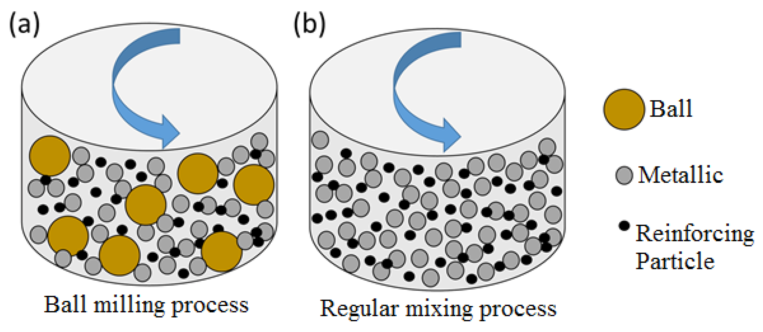
| Mechanical | Regular mixing | -Does not affect the characteristics of starting powders -Can be utilized to prepare a wide range of powders -Easy to use, fast, cost-effective and noticeably productive | -Limited capability to disperse guest powder particles, leading to relatively low poor guest-to-host adherence -Requires noticeably long mixing times to provide an acceptable dispersion state of guest particles -The produced composite powders are not ideal in terms of powder packing density and flowability |  5 wt.% B4C/Ti-6Al-4V [52]. The Ti-6Al-4V powder has been fabricated by the gas atomization process. |
| Ball milling | -Due to the presence of balls, requires shorter mixing times compared to the regular mixing -Can be employed for a wide range of materials - Relatively fast and easy to use -Can avoid agglomeration of guest particles with a high cohesiveness -The produced composite powders typically show packing densities higher than those obtained by regular mixing | -Affects the characteristics of the starting powder particles -Requires protective environment for highly reactive materials to avoid oxidation -The change in the particle morphology caused by the ball milling can adversely affect packing density and flowability of the produced powder -The wear of the balls or the container wall during the mixing process may add impurities to the powder |  5 wt.% B4C/Ti-6Al-4V [52]. The Ti-6Al-4V powder has been fabricated by the gas atomization process. | |
| Non-Mechanical | Flux-assisted synthesis | -Highly spherical powder particles are achieved -The guest particles are homogeneously distributed in the composite powder feedstock (also inside the host powder particles) -Can provide relatively high productivity -The produced composite powders benefit from high apparent packing density and flowability | -The powder production through this method is more complicated than the mechanical methods -Applicable to limited numbers of composite powder systems |  11.6 wt.% TiB2/AlSi10Mg [56]. The last manufacturing step for the production of composite powder is gas atomization. |
| Agent-assisted deposition | -The desired spherical shape of host powder particles is preserved -The guest powder constituent shows a homogeneous dispersion on the surface of host powder particles -Provides composite powders with relatively high packing density and flowability | -Relatively slow, complex and expensive |  5 wt.% Al2O3-0.15 wt.%ATCNT/NiAlCrMo [57]. The production method of the host alloy powder has not been provided. | |
| Electroless plating/Electrostatic assembly | -The spherical shape of host particles is met or preserved. -Provides acceptable attachment of guest particles to the host ones | -Low production rate -Post-processing is required -Expensive -Requires a thorough selection of system constituents and process variables |  50 vol.% Ni/Al2O3 [58]. The host powder particles are synthesized during the production of the composite powder. |
| Composite Powder SYSTEM | Guest Fraction | Guest Particle Size | Host Particle Size | Composite Powder Preparation Route | Composite Powder Micrograph | Microstructure | Remarks | Ref. |
|---|---|---|---|---|---|---|---|---|
| Aluminum Matrix Composites (AMCs) | ||||||||
| TiC/AlSi10Mg | 4 wt.% | 50 nm | 30 µm | Ball milling |  |  TiC distributed as a ring-like structure acting as reinforcement in the matrix. | -The optimization of process parameters led to the maximum part density of 98.5%. -The obtained composites showed 20% enhancement in hardness compared to the non-reinforced part. | [64] |
| SiC/AlSiMg | 10 wt.% | 550 nm | 23 µm | Regular mixing |  |  Al4C3 distributed in the AlSiMg matrix. | -The obtained composites contained ~5% porosity in their structure. -In-situ formation of Al4C3 phase resulted in 70% increase in hardness compared to the non-reinforced scenario. | [48] |
| TiB2/AlSi10Mg | 11.6 wt.% | 100 nm | 15–45 µm | Flux-assisted synthesis |  |  | -The addition of TiB2 to the Al alloy powder increased the laser absorptivity by 50%. -TiB2 particles were homogeneously dispersed in the microstructure with a strong bonding interface with the matrix. Significant improvements in the hardness, strength, and ductility were achieved compared to the non-reinforced part. | [56,65] |
| TiB2/Al-3.5Cu-1.5Mg-1Si | 5 vol.% | 3 µm | 41 µm | Regular mixing |  |  | -Incorporation of the TiB2 reinforcement significantly decreased the grain size of the matrix from 23 µm in the non-reinforced case to 2.5 µm. -The fabricated composite showed ~20% enhancement in the yield strength than that of the non-reinforced case. -Heat treatment of the composites was found to further improve the mechanical properties. | [66] |
| TiC/Al | 2.5 and 10 vol.% | Nano-scale (the exact size has not been noted) | 11.3 and 5.9 µm |  |  | -The developed composite powders showed noticeably higher laser absorptivity than that of pure Al. -The fabricated composites had significantly superior strength, elastic modulus and thermal stability compared to the non-reinforced counterparts. -The improved mechanical properties were attributed to the incorporation of well-dispersed TiC particles, matrix grain refinement, and strong reinforcement/matrix interfacial bonding. | [67] | |
| Nano-SiC/AlSi7Mg | 2 wt.% | Mean of 40 nm | Mean of 35 µm |  |  | -The nucleation provided by the nano-SiC particles led to the noticeable grain refinement of the matrix. -The microstructure contained Si, Mg2Si and nano-Al4C3 as reinforcement to the matrix. -Compared to the non-reinforced scenario, the produced composites showed improved hardness, strength and ductility. | [68] | |
| Gr nano-platelet/AlSi10Mg | 1 wt.% | NA | 20–63 µm | Ball milling |  |  | -By adding graphene nanoplatelets (GNPs) to the Al alloy matrix, the hardness, strength and wear resistance of the developed composites were improved. The self-lubricating property of the GNPs was found to decrease the coefficient of friction in the fabricated composites. | [69] |
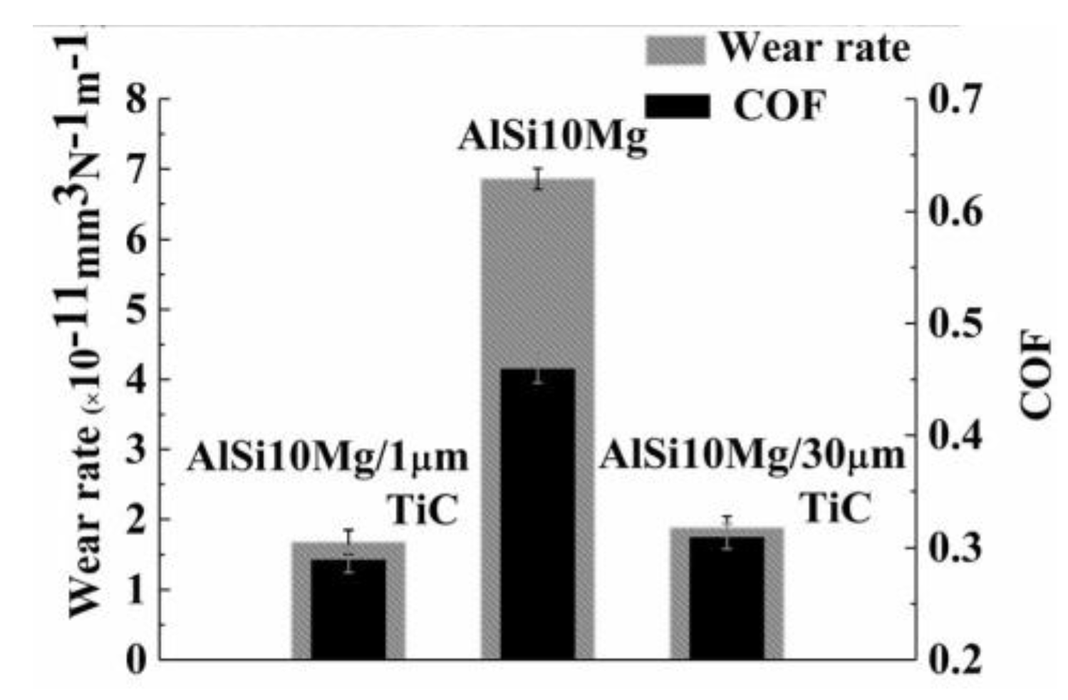
| Micro-Submicron TiC/AlSi10Mg | 15 wt.% | Micron scale(30–50 µm)Submicron scale (200 nm-2 µm) | Mean of 42 µm | Ball milling | NA |  | -~40% increase in the laser absorptivity and consequently the improved processability were achieved by adding TiC constituent to the Al alloy powder. -The composites containing micron-scale TiC were less homogeneous and uniform in terms of the dispersion of reinforcing particles in the microstructure. -Densities as high as 98% were obtained. -Improvements in the hardness, strength and wear resistance were obtained through composite fabrication. -Composites containing submicron TiC particles showed superior strength and wear resistance compared to those having micron-scale TiC particles. | [53] |
| CNT/AlSi10Mg | 1 wt.% | Inner diameter (5–10 nm)Outer diameter (20–30 nm)Length (10–30 µm) | NA | Ultrasonication followed by drying |  |  | -While still existing in the microstructure, the laser and thermal shocks subjected to the carbon nanotubes (CNTs) led to their decreased length. -The portion of CNT which reacted with the molten Al alloy paved the way for the formation of Al4C3 phase. -The fabricated composites were accompanied by ~10 and ~20% increase in the hardness and the tensile strength compared to the non-reinforced state. | [70] |
| Al2O3/Al | 15 wt.% | Mean of 26.6 µm | Mean of 33 µm | Ball milling |  |  | -The loss of Al2O3 during SLM processing was observed. -The decrease in the scanning speed and the hatch spacing led to the elevated Al2O3 loss. -The main mechanism acting behind the Al2O3 loss was its reduction reaction by the Al. | [71] |
| TiB2/AlSi10Mg | 3.4 vol.% | <100 nm | 15–53 µm | Flux-assisted synthesis |  |  | -The fabricated nano-TiB2 reinforced AlSi10Mg matrix composites showed equiaxed grains in the matrix with no preferred crystallographic texture. -The composites exhibited drastically higher strength and ductility compared to the non-reinforced AlSi10Mg case. This was attributed to the presence of nano-TiB2 reinforcing particles and their effects on the grain refinement of the matrix. | [72] |
| Al coated-Gr/AlSi10Mg | 1 wt.% | NA | 15–50 µm | Organic Al reduction method followed by dry ball milling |  |  | -The graphene nano-platelets were coated by Al to overcome the wetting problems associated with the interaction of solid graphene platelets with the molten Al during SLM. -Although the graphene could survive during the SLM process, aluminum carbide was detected in the microstructure. The finer microstructure of the composite was attributed to the ability of graphene-coated particles to act as nucleation sites for the solidification of the matrix. -Tensile strength and elongation at break of composites increased by 11% and 13%, respectively, compared to the SLMed AlSi10Mg alloy. -The wear resistance and hardness of the composites showed 70% and 40% improvement, respectively compared to the non-reinforced condition. | [73] |
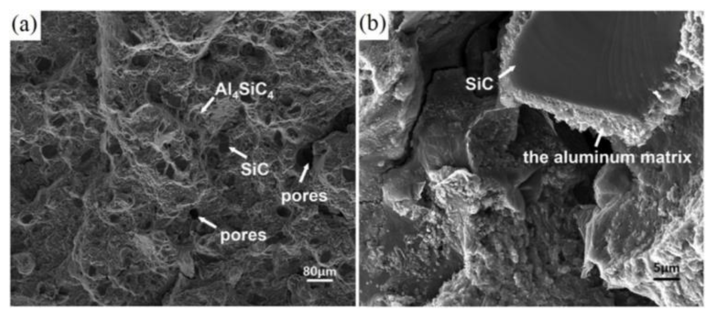
| SiC/AlSi10Mg | 15 wt.% | Mean of 46.1 µm | Mean of 33.7 µm | Ball milling |  |  | -Densities as high as 97.7% were achieved. -The SiC particles partially react with the surrounding melt at their interfaces to form needle-shape Al4SiC4 phase. -The highest hardness was reported for parts with the lowest porosity level. -The fabricated composites showed higher hardness but lower strength than the non-reinforced AlSi10Mg. This was ascribed to the premature failure caused by the crack nucleation from the porosities and large-sized SiC particles in the composite structure. | [74] |
| TiB2/Al12Si | 2 wt.% | 3.5–6 µm | 20–60 µm | Ball milling | NA |  | -TiB2 particles were homogeneously dispersed in the matrix. -Compared to the hot-pressed composite of the same system, the SLM-fabricated composites had finer matrix grain size as well as higher hardness and strength. | [75] |
| Titanium Matrix Composites (TMCs) | ||||||||
| TiB2/CP-Ti | 5 wt.% | 3.5–6 µm | 49 | Ball milling |  |  | -Compared to the non-reinforced counterparts, improvement in the hardness and strength and decrease in the flow stress and ductility were achieved for composites. This was attributed to the strengthening effects of the in-situ synthesized TiB phase and the matrix grain refinement. | [76,77] |
| TiC/CP-Ti | 15 wt.% | 50 nm | 22.5 | Flux-assisted synthesis |  |  | -The added TiC powder particles reacted with the Ti melt during SLM processing and resulted in the formation of in-situ synthesized TiC phase as the reinforcement. -The morphology of TiC phase was found to be dependent on the employed laser energy density. -Significant improvements in the hardness, elastic modulus and wear resistance were reported for the developed composites compared to the non-reinforced state. | [78] |
| B4C/Ti-6Al-4V | 0.5, 1 wt.% | 2–3 µm | Mean size of 30 µm | Ball milling |  |  | -Densification levels as high as 99.3% were achieved. -The developed composites showed significant improvement in the hardness (micro- and nano-) and compressive strength compared to the non-reinforced condition. -The fracture mode was found to be a mixture of ductile and brittle. | [79] |
| ZRO2/Ti | 3 wt.% | Mean of 270 nm | Mean of 30 µm | Ball milling |  |  | -ZrO2 particles were homogeneously dispersed in the matrix. -Combination of grain refinement strengthening and dispersion strengthening mechanisms in the developed composites led to a hardness twice that of the non-reinforced Ti. -The wear resistance of composites was significantly higher than that of pure Ti due to the dispersion strengthening and formation of a strain hardened tribolayer during sliding. | [80] |
| CrB2/Ti | 2 wt.% | −38 + 11 µm | −81 + 25 µm | Regular mixing | NA |  | -Due to the formation of in-situ TiB and partial transformation of the matrix to α phase, the developed composites showed higher hardness and wear resistance compared to the non-reinforced state. | [81] |
| B4C/Ti-6Al-4V | 5 wt.% | 1–3 µm | 15–45 µm | Ball milling |  |  | -The composite powder meeting the requirements of the SLM process was introduced. -Higher laser energy densities led to the enhanced in-situ reactions between the reinforcing particles and the surrounding melt. -The SLM process led to a microstructure extremely finer than the arc-melted one. The microstructure evolution was also found to be non-equilibrium. -Depending on the employed laser energy density, 30–80% improvement in hardness was achieved compared to the non-reinforced scenario. | [51] |
| CNT/Ti-6Al-4V | 0.8 vol.% | NA | 15–53 µm | Chemical vapour deposition (CVD) |  |  | -A novel technique was introduced to produce high-quality composite powders for SLM applications. -The relatively lower reactivity of CNTs with Ti in the fabricated composite powder system was found to provide higher amounts of non-reacted CNTs in the final TMC structure. -Compared to the TMCs with the same or slightly higher TiC contents, superior mechanical properties were achieved. | [82] |
© 2020 by the authors. Licensee MDPI, Basel, Switzerland. This article is an open access article distributed under the terms and conditions of the Creative Commons Attribution (CC BY) license (http://creativecommons.org/licenses/by/4.0/).
Share and Cite
Fereiduni, E.; Ghasemi, A.; Elbestawi, M. Selective Laser Melting of Aluminum and Titanium Matrix Composites: Recent Progress and Potential Applications in the Aerospace Industry. Aerospace 2020, 7, 77. https://doi.org/10.3390/aerospace7060077
Fereiduni E, Ghasemi A, Elbestawi M. Selective Laser Melting of Aluminum and Titanium Matrix Composites: Recent Progress and Potential Applications in the Aerospace Industry. Aerospace. 2020; 7(6):77. https://doi.org/10.3390/aerospace7060077
Chicago/Turabian StyleFereiduni, Eskandar, Ali Ghasemi, and Mohamed Elbestawi. 2020. "Selective Laser Melting of Aluminum and Titanium Matrix Composites: Recent Progress and Potential Applications in the Aerospace Industry" Aerospace 7, no. 6: 77. https://doi.org/10.3390/aerospace7060077