1. Introduction
Manufacturers of aerospace products are increasingly investigating the capabilities of metallic additive manufacturing (AM). Compared to subtractive manufacturing technologies, AM allows for a greater degree of design freedom, which enables the creation of novel and advanced geometries. Such novel designs and geometries allow substantial reductions in weight and lower “buy-to-fly” ratios (which represent the amount of material used to manufacture a component with the associated scrap). Furthermore, AM has the potential to reduce lead time and manufacturing costs significantly [
1,
2].
Despite these benefits, AM comes with manufacturing constraints that limit design freedom and reduce the possibility of achieving novel AM geometries that can be produced in a cost-efficient manner [
3]. Although research is advancing and providing a host of design guidelines and best practices for AM [
4], the magnitude of factors influencing product properties (material, machine setups, powder quality, etc.) has not yet been captured in a way that is applicable for each individual AM process and design scenario [
3].
To address the ways manufacturing constraints limit achievable design freedoms, aerospace manufacturers have a number of options, each of which present some serious drawbacks:
It is possible to develop a novel design (for example with a complex geometry resulting from a topology optimization) and ensure its quality by testing a large variety of specimens. This option ensures a novel design with the requested qualities, but it substantially impacts the cost of testing to qualify for use. This strategy may be acceptable for technology demonstrations and/or cost-insensitive applications.
Manufacturers may deliberately avoid testing many specimens (and the associated costs) and develop a conservative design based on general AM guidelines found in the literature [
4]. In this way, the manufacturer efficiently develops a product with the expected quality but misses the opportunity to achieve a more radical—and perhaps better—design. For instance, a general AM design guideline is to avoid the generation of support structures; the minimum overhang angle is 45° [
5]; however, authors, such as those of Reference [
6], have demonstrated that lower overhang angles may be possible without support structures with adjustments in certain process parameters. This is known as a “fail-safe” strategy.
They can deliver a novel and radical AM geometry without performing much testing which can only be considered for applications where failures can be acceptable. Such a strategy is rarely acceptable in space applications to date but is generally denoted as a “safe-fail” strategy.
Such dilemmas are particularly relevant for manufacturers of space components interested in applying AM to achieve more lightweight and cost-efficient components for spacecraft [
7]. However, these manufacturers also need to fulfill high-quality requirements related to the extreme conditions associated with rocket launches and satellite operations. These requirements govern the need to ensure safe and reliable functionality of the product and its possible impact on the entire system. Any new technology (or material) used to manufacture a product needs to be certified for use. This need puts the focus on the validity of any new solution proposed to deliver products that meet the requirements accordingly, and all new technologies need to be qualified. For AM, knowledge on how to validate, qualify, and, ultimately, certify new products using AM technologies for applications with high requirements (e.g., structural integrity) is not yet mature. Consequently, the amount of physical testing required to certify new products may be too expensive for large-scale commercial use. This is one reason for focusing on test artifacts that can be used to qualify AM processes for typical designs and to understand how such artifacts can be used to acquire knowledge of design for additive manufacturing (DfAM) methods.
To make use of AM design freedom while ensuring product manufacturability, designers need to find a cost-efficient manner to challenge the general AM design guidelines found in the literature and to redefine the manufacturing constraints that apply to the design scenario of interest (e.g., a specific product, machine, and material). Since DfAM methods can facilitate the consideration of manufacturability aspects in the early stages [
8,
9,
10], this article presents a DfAM method that extends a type of representation traditionally used in early design—functional modeling [
11,
12]—with manufacturing constraints modeling. In this approach, the AM constraints are modeled concurrently with the generation and testing of tailored test artifacts. In this way, the knowledge gained from testing such tailored test artifacts can be capitalized by including the manufacturing constraints in the function model and using such AM constraints for component redesign.
1.1. The Impact of Additive Manufacturing (AM) on the Design of Metallic Components for Satellites
The recent advancements made in metal AM technologies are attractive for the development or manufacturing of space components, as the technology promises increased design freedom and reduced manufacturing costs enabled by efficient material allocation. For instance, AM allows for weight and material volume minimization which are drivers of costly production in low production volumes [
7]. Metal AM processes are of special interest for the space industry, because they can enable cost reductions and performance increases of high-performance and heavy metal components such as manifolds or engine components.
Researchers and industry practitioners agree that the main challenge when implementing metal AM to design new components is the lack of experience and the large number of uncertainties and unknowns associated with the constraints of the manufacturing process [
1]. First, there are non-established standards for machines and processes. Second, there is a lack of knowledge about the physical phenomena that take place during the AM process which creates difficulty in predicting the quality of a piece, as parts manufactured with AM have a complex thermal history that involves repeated fusion, directional heat extraction, and rapid solidification [
1,
4].
To capture and monitor these complex interactions among different systems, requirements, and interfaces, systems engineering tools, such as that of McInnes et al. [
13], have been suggested to support developers. Such tools enable the analysis of system architectures, general performance, and cost but do not support the generation of a concrete design nor the process of making manufacturing-related decisions. For these challenges, most approaches, such as those proposed by Boudjemai et al. [
14] or Quincieu et al. [
15], use individually generated computer-aided design (CAD) models. However, at the concrete design level, there is a limited ability to systematically capture requirements, constraints, and manufacturing method-related impacts on a design, even in cases where multiple designs are generated and tested such as presented by Boschetto et al. [
16]. This leaves developers stuck in the classical iterative design cycle [
13], resulting in the abovementioned Option 1.
In short, the recent advancements made in metal AM technologies render this technology attractive for space applications. However, new design mindsets are required to address the lack of knowledge concerning AM technologies.
1.2. Design for AM in Space Applications
Two directions for DfAM approaches have been identified in Reference [
17]. On the one hand, opportunity-driven methods focus on design freedom and aim to generate innovative geometries with new functionality, disregarding geometry manufacturability [
18]. This can be seen in the work of authors such as Orme et al. [
19], where the focus of the development process is placed on exploiting the design freedom offered by AM but paying the price of multiple manufacturing and testing cycles to verify the design (as described in Option 1).
On the other hand, manufacturing-driven methods require minimal changes to a pre-existent component geometry to comply with the manufacturing constraints of AM [
4], leading to Option 2. An example of this can be seen in the work presented by Quincieu et al. [
15], where the only mentioned adaption to AM is the decision to split a part to fit a required build volume (i.e., application of manufacturing constraints).
Option 3 is exemplified in the case study presented by Thornton et al. [
20], where the authors purposely made use of design freedom, albeit only in the form of hexagonal cut-outs in one place, otherwise only scaling the dimensions of the product. This limited use of AM design freedom, alongside a non-systematic approach for capturing and applying of AM constraints is an example of the need for an integrated DfAM method.
While the opportunity-driven and manufacturing-driven approaches initially seem to be exclusive, they are often combined. Research suggests that, as knowledge about AM processes and constraints is limited and in constant evolution, modeling manufacturing constraints can support designers in efficiently managing and using that knowledge [
21].
However, authors such as O’Brien [
1] have suggested that most extant DfAM methodologies cannot currently compensate for the lack of specific process knowledge about the complex physical phenomena that take place during an AM process.
1.3. Expectations toward a Design for Additive Manufacturing (DfAM) Method for Space Applications
Based on the above-described experiences with AM and satellite design, a DfAM method should be able to represent a product’s design space. This design space is delimited with constraints, either from the specific use-case of space applications [
7]; material properties, as seen in Booth et al. [
22]; or machine-specific impacts, as seen in the dimensioning impact in the work presented by Quincieu et al. [
15]. Within the design space, designers can take advantage of design freedom to allow for high-performance designs such as the work presented by Orme et al. [
19]. Furthermore, since, in most cases, especially those mentioned by Boudjemai [
14], the CAD model plays a large role in the analysis and verification of a product’s performance, a close coupling to an easily editable CAD model is desirable.
Several commercial space applications have already been manufactured using a wide range of AM processes for a variety of materials, including titanium, nickel superalloys, steel, and ceramic [
23]. These processes and materials have different constraints and their use can lead to different outcomes or qualities (e.g., surface roughness or mechanical properties [
24]). The relationship between the input parameters and the expected outcome was schematically shown by Sames et al. [
25] and is indeed very complex. As shown, the outcome (failed builds, mechanical properties, feature quality, etc.) is specific for each process and process parameters set. Nevertheless, many of the processes share similar constraints but with different values. For example, a powder bed fusion process may be limited by a build volume of (200 mm × 200 mm × 350 mm), while a powder feed process may be constrained by a volume of (900 mm × 1500 mm × 900 mm) [
24]. Identifying these common constraints is of great value for developing DfAM methods.
1.4. Design of Test Artifacts for AM of Space Components
The conceptual phases of the application of DfAM methods for the space industry should include iterative efforts to assess how the manufacturing processes and material properties influence product design and product quality [
1]. Assessments of the influence of manufacturing processes and material properties on product design and quality have been widely proposed in the literature about AM test artifacts [
23]. Test artifacts (or benchmark artifacts) are implemented to assess and compare the capabilities and limitations of different AM processes. Reference [
23] presents extensive reviews of AM test artifacts utilized to compare different AM machines relying on the same or different AM technologies. The authors stated that test artifacts in general are composed of a series of generic geometric features to evaluate dimensional accuracy and other parameters such as surface roughness, mechanical properties, or manufacturing time and costs. However, given that these types of test artifacts contain generic geometric features, they are often not representative of all of the geometric features of a specific product [
26]. Moreover, they often lead to the utilization of a potentially unnecessarily large number of test artifacts [
27]. The works of Rupal, Ahmad, and Qureshi [
27] and Rupal, Secanell, and Qureshi [
28] present pioneering approaches to designing test artifacts for AM. Through their novel methods, they carefully analyzed product features critical to product quality and functionality (such as parallelism and concentricity of parallel holes) and built test artifacts based on those findings. However, their methodologies are not concerned with the redesign of a product itself. The findings and lessons learned from the manufacturing of the test artifacts were not explicitly used to improve or modify the product design.
The preceding review suggests the need for a DfAM method that includes prototyping activities to manufacture product-tailored test artifacts and then iteratively modifying the product design based on the results obtained using these test artifacts. In this context, lessons learned from prototyping activities could increase knowledge about AM manufacturing constraints. Moreover, such a method would support product compliance with qualification (activities performed to demonstrate that a product or a process meets or exceeds specified quality and reliability requirements [
29]).
Designing products with features that can be qualified facilitates the introduction of AM technologies in highly regulated industries such as the space industry.
In this article, to exploit the design freedom offered by AM while ensuring product manufacturability, a model-based DfAM method is presented. Lessons learned from testing and prototyping activities are systematically captured and organized to support early design activities and reduce late (and costly) redesign and testing efforts. The method establishes a systematic, cost-efficient way of challenging the general AM design guidelines found in the literature to adapt them and make them relevant for a specific product development project and the respective AM parameters of interest.
2. Materials and Methods
This article discusses the results of a project, conducted in cooperation with three Swedish suppliers of space components, which had the objective of demonstrating the feasibility of introducing and qualifying AM technologies in space applications.
The research adopted an action research (AR, [
30]) approach featuring several workshops attended by industrial practitioners from the participating companies. Action research is a proven methodology for understanding ill-defined problems in complex organizations that describes how changes in action or practice can positively impact on the community or practice. In this research, AR was performed through a total of five workshops and four follow-up meetings attended by 10 experienced industrial practitioners from the participating companies. The industrial participants were engineers (with 12 to 30 years of designing experience) working in product development.
The first workshop focused on idea generation strategies and presented 10 designs for AM strategies, such as part consolidation and topology optimization, using examples. These strategies are summarized in the work presented by Lindwall and Törlind [
31]. The presentation of these strategies acted as random stimuli [
32] for the generation of novel concepts. Each company presented one case study product to be redesigned for AM laser powder-bed fusion (LPBF) during the workshops.
In the second workshop, function modeling techniques were implemented for continuing the design process. These techniques were preferred because they are a reliable and well-established way of designing complex products or systems in early design phases [
33,
34]. The workshop focused on functional decomposition using enhanced function–means modeling (EF–M, [
35]). Function models were then developed from this decomposition. Later, interviews were conducted at every participating company to validate the function models. A three-phase DfAM method was then developed and validated in the third workshop. In this method, a function model (FM) tree of a traditional component (manufactured with traditional manufacturing technologies) was constructed. The manufacturing constraints of the traditional technology were included. Next, the original manufacturing constraints were removed from the function tree. Lastly, AM constraints were introduced in the function tree, and the component was redesigned for AM. Details concerning this method can be found in work by Borgue et al. [
21].
However, insights from workshops 4 and 5, which were concerned with design manufacturing and qualification, suggested the need for further developing the previous DfAM method.
The observations from the workshops were transcribed and analyzed through content analysis [
36]. To protect company-sensitive information and to show the method rather than the technical details of the use cases, significant design features were extracted from the three use cases and combined in the case study presented in this article. The case study features a propellant flow connector which was verified in terms of fidelity with the industry specialists. The flow connector was redesigned for AM and then manufactured and analyzed for validation purposes.
3. Results
The data collection activities performed during the workshops and follow-up meetings highlighted several critical areas to be further explored in the context of AM design for space components.
When designing, the participants recognized that DfAM design constraints (Cs) are related to several factors such as material, machine, design geometry, and process parameters. However, as DfAM experience is scarce, the ways in which those factors constrain product design is sometimes unknown. For instance, when the same design was sent to different providers for manufacturing, geometry accuracy and surface finishing differed greatly.
Moreover, the extensive literature about AM processes was found to be not entirely applicable for specific machine and process setups. General AM design guidelines need to be refined and revaluated through test artifacts to find reliable manufacturing constraints applicable to the AM processes implemented. However, the design of test artifacts that can accurately represent relevant product features that are critical for product performance and qualification was found to be problematic.
The participants reflected on the fact that during early design stages, product design must be performed concurrently with studies on and analysis of the AM manufacturing process and the way it interacts with a product geometry. Many current DfAM strategies do not propose strategies for or palliative methods against AM unknowns such as the manufacturing limitations of a certain machine, defect generation, or surface quality. These reflections lead to the express need to develop design strategies that are able to incorporate these studies and analysis in early design practices.
These findings were used as inputs to propose a DfAM method for space components that included in the design process the iterative manufacturing of product-tailored test artifacts and posterior improvement of the product design.
3.1. Proposed DfAM Method
The proposed model-based DfAM method was developed to exploit the freedom offered by AM design freedom while ensuring product manufacturability. The method is based on function models representing a product’s design rationale in the form of hierarchically arranged objects of different types based on the EF–M technique [
37]: functional requirements (FRs), design solutions (DSs), and Cs. The proposed model extends the normal use of EF–M modeling by actively using a constraints release and replacement technique. Constraints release and replacement represents a novel strategy for identifying critical geometrical features in a design that need to be tested for manufacturability. The identified features included in product-tailored test artifacts provide valuable insights about AM manufacturing limitations (constraints) and their interaction with the product’s geometry.
The method is structured into six phases, from decomposition of the baseline design to manufacturing of the AM-optimized new design. The first three phases build on previous work by Borgue et al. [
21]. In this article, three more phases were included as presented in
Figure 1.
Functional decomposition: An EF–M model representing the traditionally manufactured product is created.
Constraint replacement: Constraints based on traditional manufacturing methods are identified and removed. In their place, AM constraints are introduced into the function model.
First redesign for AM: The function model is redesigned for AM. New DSs are developed to replace the previously removed ones. Inactive AM constraints are removed from the model.
Prototype manufacturing: Critical geometric features of the design are identified and included in various test artifacts [
38] which are then manufactured.
Function model improvement and redesign: Lessons learned from the test artifacts are used to improve the AM function model and AM design.
Iterative design improvement and manufacturing: Phases 4 and 5 are repeated iteratively.
3.1.1. Phase 1: Functional Decomposition and Modeling
A function tree of the original part is built to facilitate understanding of the product architecture. The function modeling technique EF–M [
36] was chosen because it provides a distinct modeling of constraints. However, other modeling strategies are also suitable for functional decomposition such as those proposed by Chesnut [
39]; Umeda, Takaeda, and Tomiyama [
40]; and Heller and Feldhusen [
41].
When implementing the EF–M technique, the part geometry is analyzed to find FRs directly associated to DSs. Then, constraints with an impact on specific DSs are identified and included in the function tree associated with the applicable DS. In the proposed method, a distinction is made between manufacturing constraints (Cms) and functional constraints (Cfs). This is not part of the original EF–M theory but has proven beneficial in a redesign for an AM process [
21]. Manufacturing constraints depend on the manufacturing process, such as minimum manufacturable wall thickness, while, in contrast, Cfs depend on FRs such as the maximum pressure a pipe needs to endure. The distinction among constraints facilitates the process of identifying the DSs that are only manufacturing dependent and that can therefore be targeted to be redesigned for AM. To achieve this purpose, configurable components (CCs) are implemented in the function tree as well. These CCs, introduced by Claesson [
35], are objects that encapsulate entire branches of related DSs and sub-elements to serve as components in the analysis.
3.1.2. Phase 2: Constraint Replacement
The Cms derived from traditional manufacturing methods and the DSs (and their respective sub-trees) constrained by them are pruned from the function tree. Then, the function model is re-constrained, with AM constraints being introduced to replace those previously removed. For instance, when machining a component, internal cavities cannot be manufactured (as the tool cannot reach them), which leads to the Cm that
Cavities must be reached by tools. When designing for AM, internal cavities can be manufactured. However, geometries with overhang angles smaller than 45° need support structures [
5]. As internal support structures cannot be removed, the Cm that
Cavities must be reached by tools is then replaced by the AM constraint
Minimum overhang angle, 45°. At this point, as the AM component has not yet been conceptualized, a general body of AM constraints—general AM guidelines—is considered.
3.1.3. Phase 3: First Redesign for AM
The sub-branches removed in the previous phase open the design space for a new, DfAM-guided design. Other parts of the function model, which are not pruned in this step, provide interfaces and geometry which must be retained. Under consideration of the AM constraints, making use of the explicitly freed up design space, the product is now redesigned. Through this procedure, areas in the function tree that are solely constrained by AM Cms are identified as parts of the product that can be redesigned for AM. Then, a new function tree redesigned for AM is built, and a new product geometry can be conceived. At this point, the focus should be on applying the minimum number of Cms as possible (minimally restrictive constraints [
42]) in order to not over-constrain the design space, facilitating AM design freedom while ensuring product manufacturing. Following the definitions established by Patterson and Allison [
42] in their design framework for ensuring manufacturability of mechanical components, once AM constraints are identified, they can be classified as active, inactive and unnecessary (IU), inactive and redundant (IR), inactive and internally dominated (IID), or inactive and externally dominated (IIE).
Table 1 introduces the terminology for constraint activity according to Patterson and Allison [
42].
At this point, as manufacturing constraints are geometry-dependent [
43], components with different geometries have different active AM constraints in their function model (FM) trees.
3.1.4. Phase 4: Prototype Manufacturing
Additive manufacturing product design must be performed concurrently with studies and analysis of the AM process to be implemented [
1,
3]. Therefore, studies on the AM process of interest must be closely related to product geometries [
27].
In this phase, to assess design manufacturability, the AM manufacturing constraints identified in the previous phases are evaluated [
38]. Test artifacts are used to evaluate which manufacturing constraints found in the literature are applicable to the product geometry and AM process implemented. For instance, the minimum overhang angle for support avoidance is known to be 45° [
5]; however, this value is a generalization, and the actual minimum overhang depends on material and process parameters [
6]. To evaluate manufacturing constraints in the test artifacts, the constraints are parametrized, and the different parameter values evaluated. In a constraint such as minimum overhang angle, the overhang angle is considered a parameter. For its evaluation, geometries with an overhang angle variation from 0 to 45° are manufactured. If machine process setups are also considered a variable parameter, a multiparameter evaluation should be performed following procedures such as design of experiments (DOEs, [
44]). The constraint evaluation through test artifacts is complete when the constraint is established, which means that a concrete value is defined for the set of manufacturing process parameters of interest. The importance of distinguishing between active and inactive constraints is highlighted in this phase, as only active constraints are included in the test artifacts.
3.1.5. Phase 5: Function Model Improvement and Redesign
The parametric analysis from Phase 4 provides an accurate understanding of the AM constraints involved in the design. These lessons learned should be documented and introduced in the function model as Cms to systematize and preserve the information. The component is then redesigned according to the improved function tree. In the case of overhangs, test artifacts may have demonstrated that the minimum overhang angle (for the material and process parameters of interest) was less than 45°. In that case, the Cm corresponding to Minimum overhang angle, 45° would change, and the design can be changed accordingly. When the component is redesigned, Cms that were inactive in the previous design can become active due to the changes in geometry; these recently active constraints should be included in the FM tree. For example, if an earlier version of the design had attachment holes with a diameter larger than the minimum manufacturable hole, the Minimum manufacturable hole diameter was, at that time, an IU Cm. However, if the design changes and the hole diameters are reduced, the Cm Minimum manufacturable hole diameter can become active.
3.1.6. Phase 6: Iterative Design Improvement and Manufacturing
If, during the redesign process from Phase 5, new AM constraints become active due to the changes in component geometry, they must be evaluated in test artifacts. If this is the case, Phases 4 and 5 must be repeated until every active manufacturing constraint has been evaluated. When every active manufacturing constraint is established, a new and improved AM design can be manufactured.
3.2. Application of the DfAM Method: Redesign of a Propellant Flow Connector
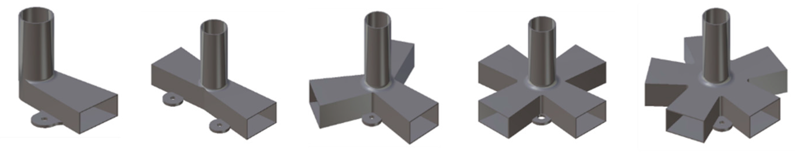
To illustrate the development of the proposed method, a propellant flow connector for satellite applications was designed. The flow connector was developed to represent significant design features from the three use cases presented at the workshops. Moreover, it was verified in terms of fidelity with industry specialists. The flow connector is a 5 cm tall pipe structure connecting interfaces of different shapes and dimensions that has the main function of guiding fluid with a pressure of 300 bar. Different models of the connector can have from two to six interfaces. One interface corresponds to a vertical circular inlet (1 mm diameter), while the other (up to) five interfaces correspond to horizontal rectangular outlets. Flow connector designs with two to six interfaces are presented in
Figure 2.
Currently, the outer shape of the connector was machined from a steel block, the vertical inlet was drilled, and the horizontal outlets were milled from the bottom. The cavity resulting from this process was welded shut with a plate. Afterwards, “ears” for screwing the connector onto the satellite were integrated into the product. In this case study, the flow connector was redesigned to be manufactured with AM LPBF.
3.2.1. Functional Decomposition
As detailed in
Section 3.1, the first step in the redesign process was a functional decomposition. During this procedure, FRs, DSs, and Cs were identified by an expert panel. Then, those FRs, DSs, and Cs were organized in a hierarchical function tree, as shown in
Figure 3, where DSs were connected with other DSs through “iw” connections and Cs through “icb” connections. More details about this process can be found in previous work by Borgue et al. [
21].
Lastly, the function tree was encapsulated into different CCs (tube, outlet, inlet, and satellite interfaces) to ease the identification and substitution process as shown in
Figure 3.
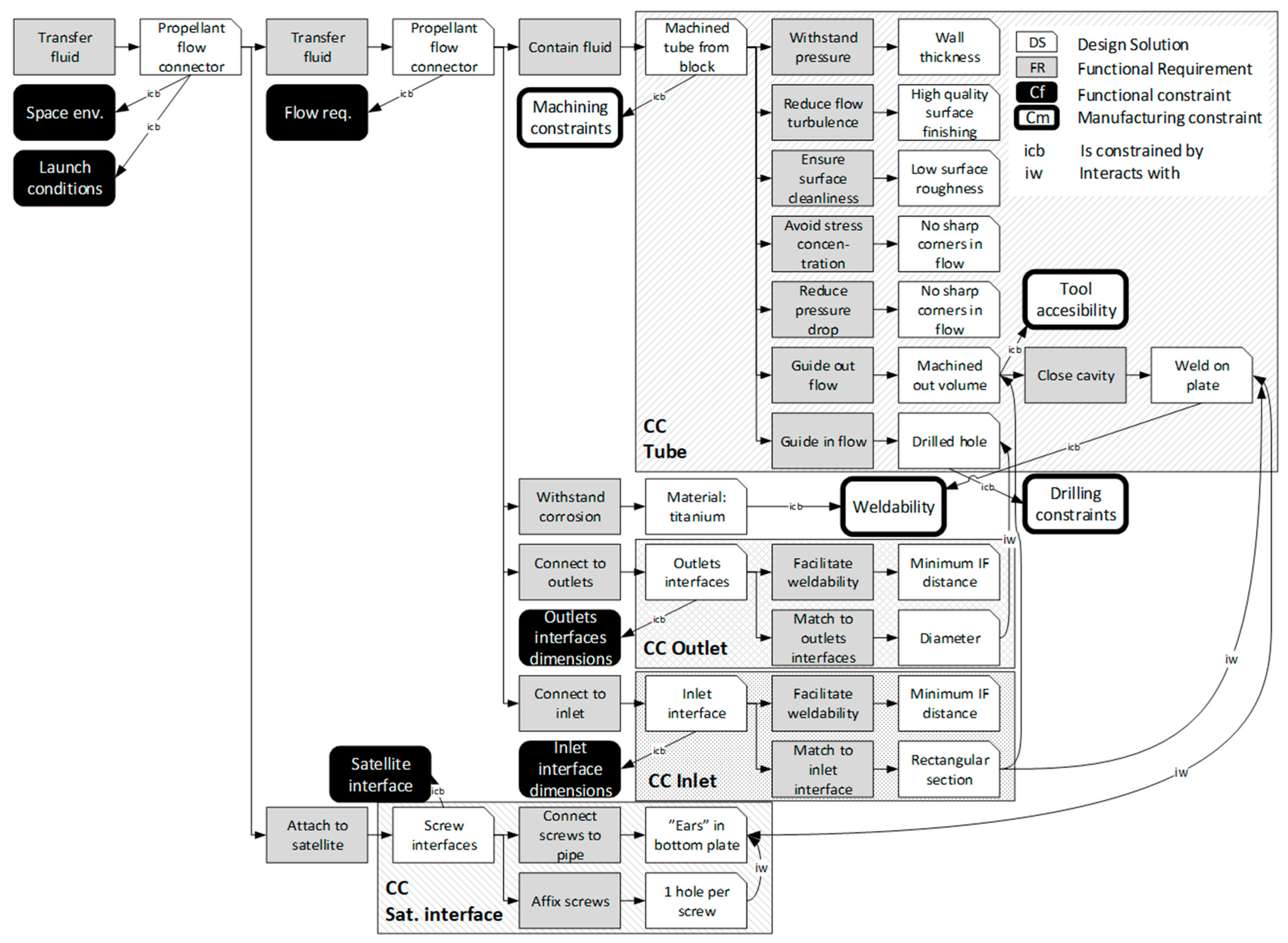
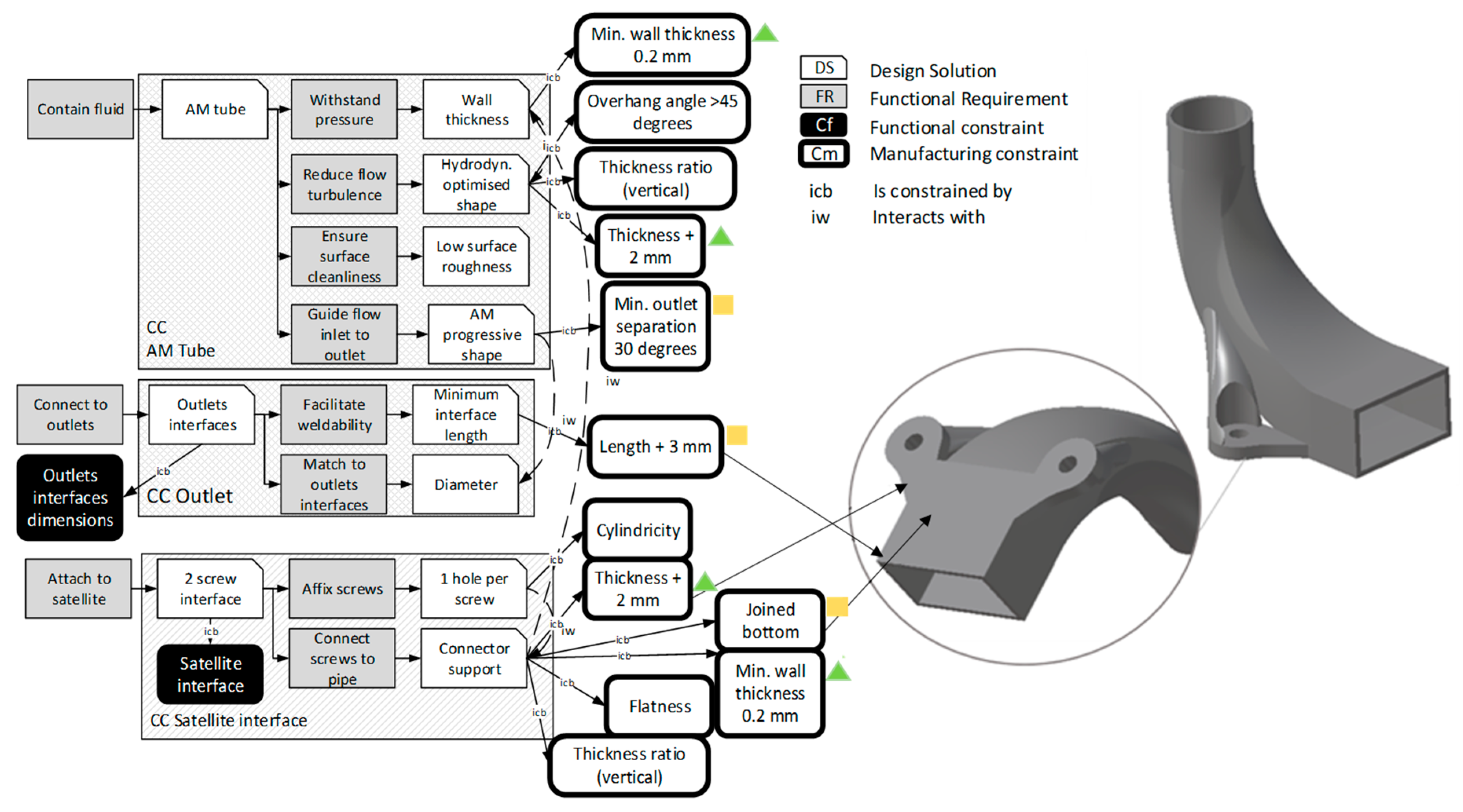
3.2.2. Constraint Replacement
Captured in the function model in
Figure 3 are both Cfs and Cms. Since the welded connection with the system level (inlet and outlets) cannot be changed, the respective Cm was retained. However, due to the change in manufacturing methods (from machining to AM), the Cm
Machining constraints for the CC
Tube was removed. Its removal frees the design space for the entire CC
Tube. Moreover, due to the “iw” connection from the DS
Weld on plate in the CC
Tube to the DS “
Ears”
in bottom plate in the CC
Satellite interface, the CC
Satellite interface was affected by the design change as well and could be redesigned.
To replace the traditional manufacturing constraints with appropriate AM constraints, LPBF constraints were obtained from the European Powder Metallurgic Association [
5]; these are presented in
Table 2. Due to the reduced size of the propellant flow connector, constraints such as the maximum building volume or the maximum channel diameter (10 mm) to avoid support structures were not considered in the analysis.
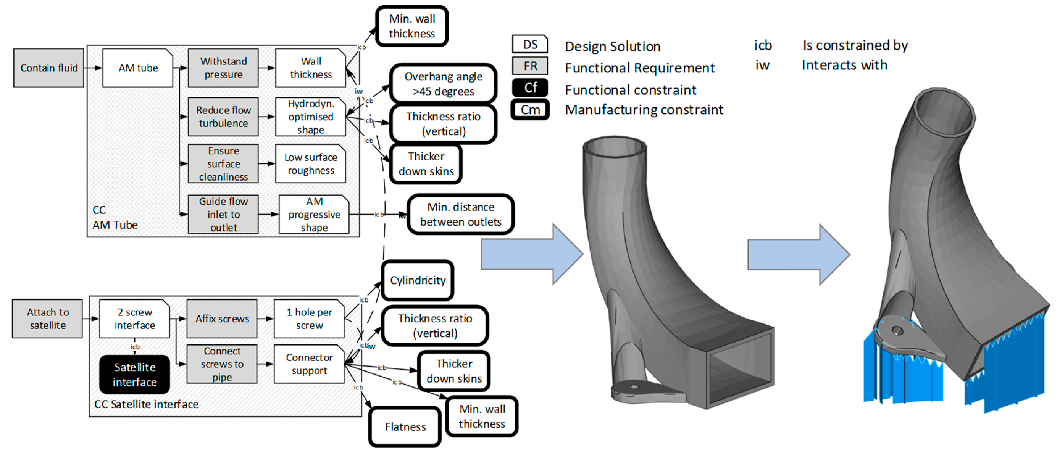
3.2.3. Component Redesign for AM
After the CC
Tube design space was freed, the DS
Machined tube from block was removed and replaced by the
AM Tube, which was constrained by the Cm
LPBF constraints.
Table 2 lists the LPBF manufacturing constraints. Making use of the wider design freedom in AM, a new design based on physics models was created for the tube part. The design takes the form of a curved connector shape with a continuous change in cross-section which reduces fluid resistance. This shape connects inlet and outlet interfaces while minimizing the energy loss of the fluid [
45]. The FR and DS in the CC
AM Tube and
Satellite interface are illustrated in
Figure 4. Based on the previously discussed AM constraints, the DS
Wall thickness was constrained by
Minimum wall thickness. At the same time, the DS
Hydrodynamically optimized shape was constrained by
Overhang angle > 45°,
Thickness ratio (vertical),
Thicker down skins, and the
Maximum height-to-diameter ratio. As the inlet was connected to one or more outputs, the DS
AM progressive shape was constrained by
Minimum distance between outlets. This latest constraint followed the same principle of the minimum diameter for AM holes. If the distance between outlets is too narrow, powder particles can be trapped in between, which can generate surface defects.
The connectors for attaching the propellant tube to the satellite interface were integrated into the tube structure and were also redesigned as the DS
Connector support.
Connector support was constrained by the LPBF constraints
Minimum wall thickness,
Thicker down skins,
Thickness ratio (vertical), and
Flatness. The DS
Affix screws was constrained by
Cylindricity.
Figure 4 presents the CC
AM Tube and CC
Satellite interface for the redesigned connector model next to the redesigned geometry and build orientation. As CC
Inlet and CC
Outlet were not redesigned, they are not included in
Figure 4. In the proposed component design, there were no holes with diameters below 0.4 mm; for this reason, this constraint was not further considered in the FM analysis (the constraint was IU).
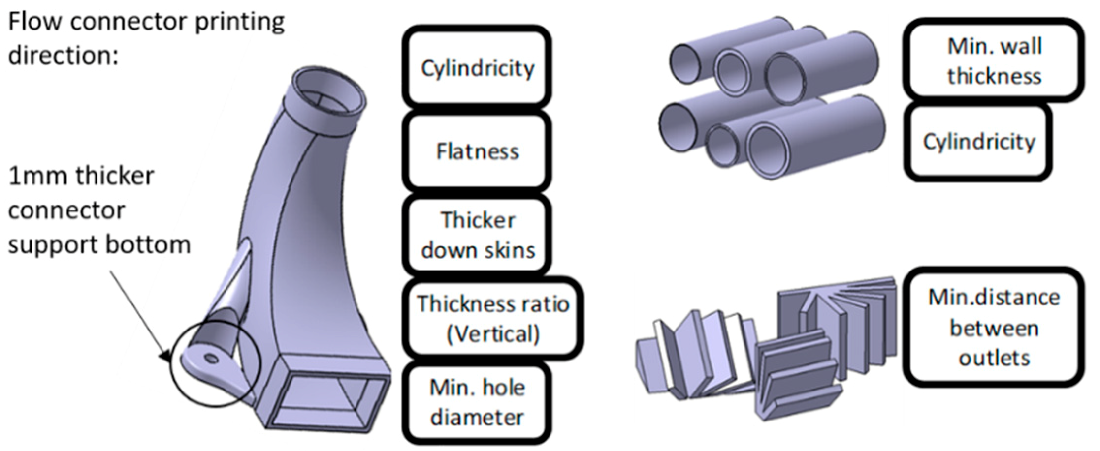
3.2.4. Prototyping
Additive manufacturing powder bed processes are based on complex physical phenomena, and AM manufacturing constraints are largely geometry dependent [
43]. For this reason, each manufacturing constraint obtained from the literature must be evaluated for the product geometry of interest. However, several manufacturing constraints can be evaluated in the same test artifact as exhibited in
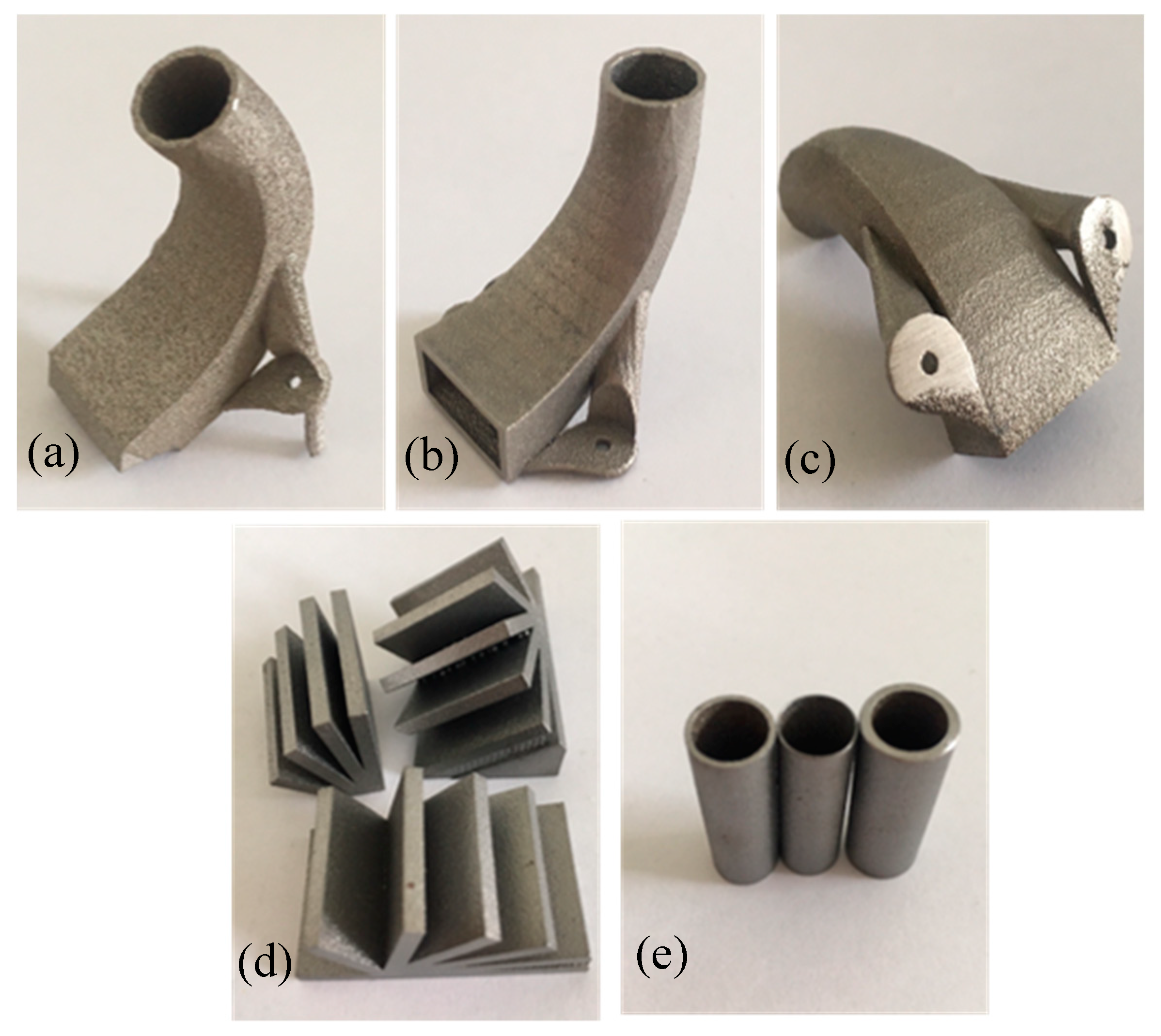
Figure 5.
Figure 5 presents the three types of test artifacts chosen to evaluate the manufacturing constraints obtained from the literature in respect to the product geometry. In this case, due to the reduced size of the flow connector, it was possible to manufacture its entirety as one of the test artifacts to assess the constraints
Thickness ratio (Vertical),
Thicker down skins,
Flatness, and
Cylindricity. This test artifact had one inlet and one outlet and was printed in the same printing direction as a final product with one outlet would have.
The constraint Thicker down skins was translated into a 1 mm thicker connector support bottom. The constraint Minimum wall thickness was evaluated with the constraint Cylindricity using tubes with different wall thicknesses. The constraint Minimum distance between outlets was evaluated with test artifacts that were similar in appearance to an open book to assess how close the “book leaves” can be without observing defects between them. Moreover, the book-like test artifacts were printed in various orientations to observe how the orientation in the AM machine influences defect generation. These results shed light on the possible printing orientations of flow connectors with more than one outlet.
Figure 6 shows the test artifacts that were manufactured with a LPBF machine (from Electro Optical Systems (EOS), GmbH, Munich, Germany) EOS M290 equipped with a Yb-fiber laser. The feedstock material was a gas-atomized stainless steel 316L powder with particle size distribution of 20–53 µm. The artifacts were fabricated utilizing standard process parameters provided by EOS. These parameters included a strip scanning strategy with a 67° rotation and contour scanning as described in detail by Leicht, Klement, and Hryha [
46]. The parameters were optimized for high density, low surface roughness, and high dimensional accuracy, and they adjusted automatically for different design features such as up and down skins. These sets of parameters were used for the manufacturing process of the final product as well.
Figure 6a exhibits the flow connector after removal from the build plate without any post-treatment. In
Figure 6b,c, the support structures were removed, the part was sandblasted, and 1 mm of the connector support bottom was machined out. However, it can be noted in
Figure 6c that surface defects persisted and that more material must be machined out to improve surface quality. Moreover, as the ears (for connecting to the satellite) were separated from each other (
Figure 6c) and the post-processing activities in this case were manual, there was a risk of having an uneven flow connector bottom after post-processing.
The most convenient way to remove the support structures generated in the outlet was to cut a large portion of the outlet structure. This process eliminated 3 mm of the outlet interface, the length which serves for connecting the flow connector to other devices.
The book-like test artifacts (
Figure 6d) show that the separation among outlets should be greater than 30° to avoid an inferior surface roughness and dimensions among the outlets; below 30°, the presence of unmelted particles on the outlet surfaces was observed. Moreover, on certain building orientations, support structures among the leaves were observed, as the overhang angle was too low.
The pipe-like test artifacts (
Figure 6e) were manufactured with an 8:1 height-to-diameter ratio and wall thicknesses from 0.2 to 1 mm to test the connector’s structural stability. The parts were all successfully manufactured without any build failures. Furthermore, based on visual inspection, it seems that the presented design had a high manufacturing quality.
3.2.5. Function Model Improvement and Redesign
Based on the results obtained from the test artifacts, several constraints were updated and others created.
Table 3 summarizes the lessons learned from the prototyping activities.
To remove the support structures from the connector outlet, 3 mm of the outlet length was cut off. A new constraint (Length + 3 mm) was added to the DS Minimum IF distance.
As the support removal procedure is manual, complying with the constraint Flatness was problematic while having two separated ears. For this reason, the constraint Joined bottom was included for the DS Connector support.
To ensure the complete removal of the rough down facing surface, the constraint Thicker down skin was replaced by Thickness + 2 mm in the DS Connector support.
From the results of the pipe-like test artifacts, the constraint Minimum wall thickness was established as Minimum wall thickness = 0.2 mm.
The results from the book-like test artifacts suggested the creation of the constraint Minimum outlet separation = 30°.
The sole evaluation performed regarding the constraint Thickness ratio (Vertical) was to determine whether the current design presented rough surfaces due to the poor heat dissipation. As the features implemented in the design seemed to avoid this phenomenon, this constraint remained unchanged.
The previously mentioned changes in the manufacturing constraints were introduced in the function model presented in
Figure 7.
3.2.6. Iterative Design Improvement
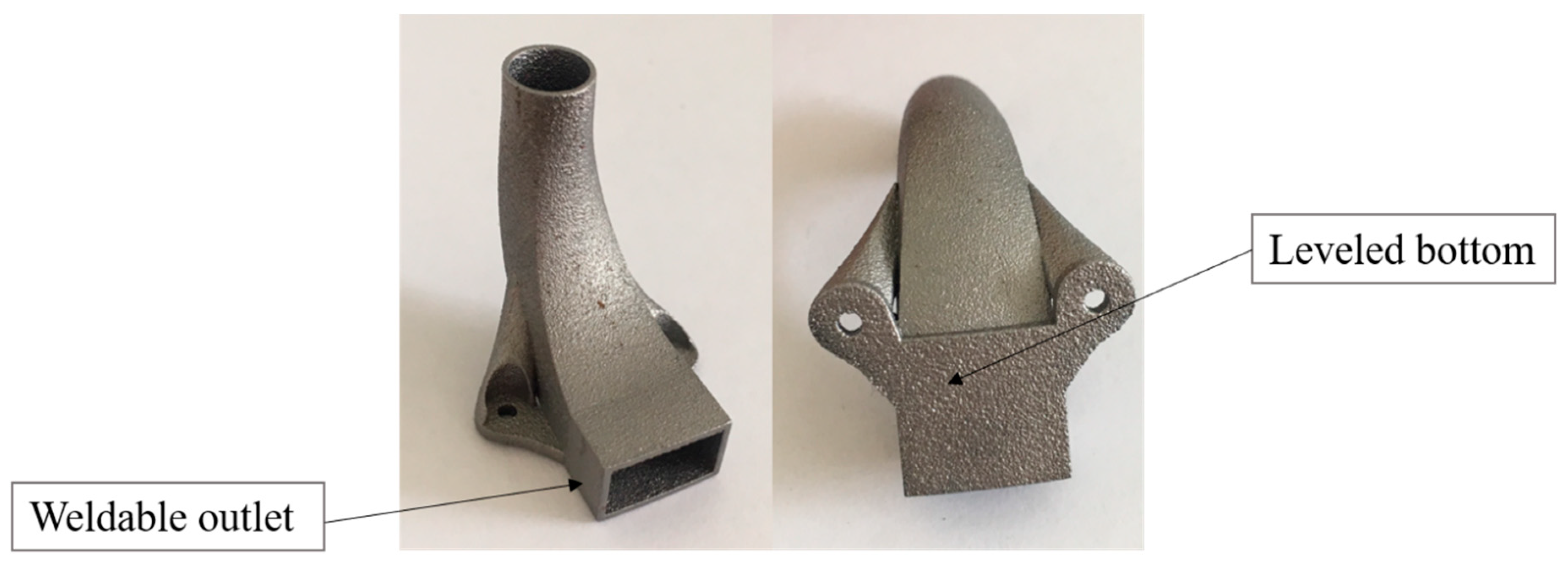
After updating the function model with updated and new manufacturing constraints, a new propellant flow connector implementing the same AM machine and process parameters used for the prototypes was manufactured. The new propellant flow connector is presented in
Figure 8. The design has a joined bottom and, as the outlet length (to compensate for the removal of support structures) and the connector support thickness were extended in the design, the outcome was a connector with a weldable outlet and a smooth bottom. As the manufacturing of the second flow connector was successful, no other changes in the component geometry were required, and every AM constraint was established as suggested in
Table 4. Therefore, there was no need to continue the prototyping activities and design iterations.
4. Discussion
In this article, a DfAM method intended to support designers in considering how manufacturing processes and material properties influence product design was proposed. The method is based on refining the general AM design guidelines found in the literature [
5] to make them relevant for a specific product development project and the respective AM parameters of interest. The AM design guidelines are represented in relation to the product’s function structure in the form of manufacturing constraints. This representation is made by implementing the EF–M function modeling technique. As manufacturing constraints are dependent on various process parameters (such as the material used, machine setups, and geometry [
3]), the constraints obtained from the literature need to be adapted for the product to be designed. This is done through the manufacturing of test artifacts. The literature on the development of AM test artifacts is vast [
26]; however, there is a lack of methodologies for selecting test artifacts based on product features. The modeling approach proposed in this paper is intended to support designers in evaluating the manufacturability of specific product features, thereby contributing to shorter development times and time to market. One of the latest methodologies for test artifact design based on product features was proposed by Rupal, Ahmad, and Qureshi [
27] and Rupal, Secanell, and Qureshi [
28], where product-critical features were identified and included in AM test artifacts. The method presented in this article takes this procedure one step forward by utilizing the results from the test artifacts to iteratively improve the design of a product and ensure its manufacturability and quality. Moreover, studies conducted by authors such as Booth et al. [
47] highlight the need for establishing process- and product-specific guidelines to accurately account for the unique limitations of each AM process. Implementing product-tailored design artifacts supports the development of a knowledge database or design guideline adapted to a specific product and AM process.
In this article, the test artifacts were specifically designed based on the constraints and geometry features available in the product in correlation with the machinery, material, and manufacturing parameters used. The results from these test artifacts were reintroduced into the function model, where they were used to update previous constraints or even create new ones. Therefore, the function model acts as a model-based database for product and manufacturing process information which can be reused to further develop a product or product family and increase AM-documented knowledge. Similar development of product families based on EF–M models has been described by Johannesson and Claesson [
37]. Function modeling and the carryover of the DfAM constraints in such a scenario allow for continuous knowledge capture and development. Moreover, a model-based database that includes both conceptual design information (DSs) and manufacturing information (Cms) has the potential to act as a boundary object [
48,
49] between manufacturing and design teams. Experts’ manufacturing knowledge (perhaps tacit) can be documented in the model with ease and communicated to designers or less experienced engineers thus facilitating communication and coordination efforts that could further reduce development time and costs. Furthermore, as AM constraints are machine-dependent, early constraint modeling efforts can support decision-making procedures concerning future machine purchases and technology development activities.
The function model supports the distinction between active and inactive manufacturing constraints. The identification of active constraints reduces and clarifies the geometrical features to be tested in design artifacts. In the case study, for instance, when the machining constraints were replaced by AM constraints (before the first AM redesign was created), the minimum manufacturable AM hole (0.4 mm diameter) was considered an active constraint. However, as the AM flow connector did not have such small holes or pockets, that constraint became IU and was not included in the test artifacts. This distinction and the results it enabled resonate well with the work of authors such as Patterson and Allison [
42] where distinguishing between active and inactive constraints facilitated the design of manufacturable components while imposing as few restrictions on the design space as possible (minimally constrained).
Table 1, in
Section 3.1, presents five constraint distinctions (active, IU, IR, IID, and IIE, [
42]). However, due to the simplicity of the case study developed in this article, only the use of active and IU constraints were evidenced. Moreover, as the case study was conducted for illustrative purposes, the AM active constraints identified and tested in the case study were not a complete set of active manufacturing constraints for the flow connector. Furthermore, no verification or validation was conducted to be able to confirm that the identified constraints and their distinction (active or inactive) were accurate.
In a real design scenario, during long design processes for complex or critical products, it may be possible to identify a larger number of active Cms. However, in such a scenario, the implementation of the five constraint distinctions is recommended, as some manufacturing constraints might be overridden by other design requirements such as fatigue response, material specifications, or cost limitations. Regarding active and inactive constraints, their identification starts concurrently with the design conceptualization with assumptions being based on previous design experience. The iterative nature of the proposed method nevertheless facilitates the continuous identification and distinction of constraints thus providing the possibility of reevaluating previous assumptions. Furthermore, the documentation ability provided by the function model can be an advantage when identifying and distinguishing constraints in future design projects.
The proposed product-tailored test artifacts contribute to ensure component manufacturability which has the potential of reducing costs for development, manufacturing, and, later in the product development process, qualification activities. Moreover, product-tailored AM test artifacts contribute to reducing material consumption and prototyping costs [
27].
The presented method emerges from an empirical study performed through workshops with industrial practitioners from three different space component manufacturers. A main reflection reported by the industrial practitioners is that the AM product design must be performed concurrently with the analysis of the AM manufacturing processes and especially on the ways that such process parameters interact with the product geometry. Such reflections are in accordance with the literature (e.g., [
1]). Moreover, the workshop participants recognized that, at present, DfAM design experience is limited, and the extensive literature on AM processes is not entirely applicable for specific geometries, machines, and process setups. General AM design guidelines must be refined and re-evaluated through test artifacts. These results resonate well with those presented by authors such as Rebaioli and Fassi [
26]; Rupal, Ahmad, and Qureshi [
27]; and Rupal, Secanell, and Qureshi [
28] who focus their work on the design of AM test artifacts.
In the case study, AM constraints were identified and evaluated based on product geometry and process parameters. To ensure reliable, repeatable, and structured results, implementing techniques, such as DOEs [
44], are considered for a future extension of the presented method. The use of these techniques has proven to be a reliable and efficient strategy for optimizing testing activities in the aerospace sector [
50]. Currently, research on how process parameters impact product quality is scarce [
51]. However, several authors have addressed this knowledge gap with the implementation of various DOE techniques, such as central composite design [
51], half-factorial design [
52], or Taguchi methods [
53].
When evaluating the minimum distance between outlets, for instance, a DOE can be established for the parameters angle between outlets and building orientation. In the presented method, a DOE technique was not applied but is considered a promising extension of the method.
The method proposed in this paper requires a certain degree of abstraction and formalism which often implies additional efforts by designers and the organization in general. However, there are some considerations that motivate such an increased degree of formalism:
5. Conclusions
To support designers in making use of AM design freedom while ensuring product manufacturability, a DfAM method was presented. The method is based on the main assumption that the lessons learned from testing and prototyping activities can be systematically captured and organized to support design activities. To enable this capturing, this study introduced a DfAM method in which a representation often used in early design, a function–means model, was extended with the introduction of a new model construct, Cm. In this approach, the association between AM Cms and DSs was made by the concurrent testing of tailored test artifacts based on the design scenario of interest.
The method was applied to the redesign, manufacturing, and testing of a flow connector for a satellite. The application in this case study illustrates how the method can be used as a cost-efficient method to challenge the general AM design guidelines found in the literature and as a means to redefine and update manufacturing constraints. Furthermore, the DfAM method can be used to document and manipulate the associations between product functions, DSs, and AM manufacturing constraints thus providing the basis for a manufacturing constraints database to be used for future designs. This can contribute to the effective increase in the AM knowledge inside an aerospace organization, thereby shortening future products’ development times and costs.


