Design and Development of a Planetary Gearbox for Electromechanical Actuator Test Bench through Additive Manufacturing


Department of Aerospace and Mechanical Engineering (DIMEAS), Politecnico di Torino, 10129 Turin, Italy
*
Author to whom correspondence should be addressed.
Actuators 2020, 9(2), 35; https://doi.org/10.3390/act9020035
Submission received: 7 April 2020
/
Revised: 23 April 2020
/
Accepted: 29 April 2020
/
Published: 1 May 2020
Abstract
:The development and validation of prognostic algorithms and digital twins for Electromechanical Actuators (EMAs) requires datasets of operating parameters that are not commonly available. In this context, we are assembling a test bench able to simulate different operating scenarios and environmental conditions for an EMA in order to collect the operating parameters of the actuator both in nominal conditions and under the effect of incipient progressive faults. This paper presents the design and manufacturing of a planetary gearbox for the EMA test bench. Mechanical components were conceived making extensive use of Fused Deposition Modelling (FDM) additive manufacturing and off-the-shelf hardware in order to limit the costs and time involved in prototyping. Given the poor mechanical properties of the materials commonly employed for FDM, the gears were not sized for the maximum torque of the electric motor, and a secondary torque path was placed in parallel of the planetary gearbox to load the motor through a disc brake. The architecture of the gearbox allowed a high gear ratio within a small form factor, and a bearingless construction with a very low number of moving parts.
1. Introduction
Electromechanical Actuators (EMAs) are devices intended to convert electrical power into mechanical power to achieve closed-loop control of the position of a mechanical component. The extensive use of EMAs for industrial applications dates back to the second half of last century [1,2]. In the last decades, this technology has gradually gained relevance for aerospace applications [3,4,5,6,7], starting from non-flight-critical subsystems. Currently, EMAs are employed for secondary flight controls of last-generation commercial and fighter aircraft, according to the all-electric and more-electric aircraft paradigms [8,9,10,11], as well as for primary flight controls of small Unmanned Aerial Vehicles (UAVs).
The use of electromechanical technology in place of a more traditional hydraulic actuation system brings several advantages. The lack of a centralized hydraulic power generation system allows for a significant reduction in weight and power consumption. Safer operations and easier maintenance are possible through the elimination of potentially flammable and toxic hydraulic fluids. Power transmission from the aircraft engines to the actuators is achieved through electrical lines, which are lighter and allow for a more flexible installation than hydraulic hoses.
On the other hand, EMAs also feature some disadvantages with respect to hydraulic systems. The power-to-weight and force-to-weight ratios of high-performance hydraulics are still unmatched by electromechanical systems. Additionally, the failure modes of EMAs are inherently more dangerous than hydraulic actuators for flight controls: a failure of the mechanical transmission of an EMA may lead to jamming the actuator and locking in place the controlled aerodynamic surface; for this reason, redundancy management always requires including disengaging devices in the design of the EMA. The same risk is virtually inexistent in hydraulic systems [12,13,14].
To address this issue and ease the diffusion of EMAs for aerospace applications, advanced risk mitigation strategies are needed. In this context, Prognostics and Health Management (PHM) [15,16,17] offer computational tools aiming at the estimation of the remaining useful life of equipment; Lei et al. [18] and Wang et al. [19] propose a review of condition monitoring techniques applied to planetary gearboxes. Such tools rely either on data acquired from the operation of systems, or on detailed simulation models. Even in the latter case, field data are still needed to calibrate the models. As highlighted by Djeziri et al. [20], large experimental datasets on operating parameters of EMAs are not commonly available, and databases would be required, including both the effects of faults on system operation and the propagation of damages. For this reason, in this paper, we propose the design of an electromechanical test bench intended to simulate the operation of an actuator in different conditions, and under the effect of different fault modes. Additionally, the design of the actuator with an open architecture will enable the installation and testing of innovative sensors for diagnostics. The test bench will be employed to collect datasets for the calibration of physics-based dynamical models [21] of the actuator, and for the training of machine learning computational tools for fault detection. The rate of propagation of damages can be measured as well, although it may be not completely representative of real operating scenarios due to different materials, manufacturing technologies and environmental conditions (e.g., externally induced vibrations and load factors) that are difficult to quantify or to reproduce on a static test bench.
2. Layout of the EMA Test Bench
The test bench, currently under assembly, reflects the architecture of a typical actuator for secondary flight controls, similar to those commonly found on leading edge slats. For such applications, usually a rotary output with a limited angular range is required. Conversely, actuators for primary flight controls often feature a linear output. However, this is really required only for the retrofit of EMAs on existing airframe designs. If an airframe is designed from the beginning accounting for the use of electromechanical primary flight controls, rotary actuators can enable a better use of the available space, leading to more compact and power dense designs. Additionally, the elimination of a rotary-to-linear conversion device (e.g., a ballscrew or a jackscrew) significantly reduces the complexity and improves the reliability of the EMA. For example, Brassitos et al. [22] propose the design of an integrated rotary EMA for space application, able to outperform currently employed off-the-shelf solutions in terms of output torque, while reducing the size of the assembly. The general layout of the test bench is shown in Figure 1. A Permanent Magnet Synchronous Motor (PMSM) and its power inverter are connected to a reduction gearbox to drive the user. A high-resolution encoder measures the position of the output shaft in order to provide closed-loop control. A Programmable Logic Controller (PLC) manages the command time-history, executes the Proportional-Integral-Derivative (PID) position control, and at the same time works as a data logger.
The design of the gearbox allows one to change the backlash between the output shaft and its encoder; additional failure modes can be injected by replacing healthy gears with artificially damaged ones, e.g., affected by cracks or eccentricity. In this context, the system was designed with a modular and easily accessible architecture, allowing for the installation of several sensors for health monitoring purposes. For example, the backlash and stiffness of the transmission can be estimated by comparing the angular position of the motor to the reading of the output shaft encoder. Additionally, the accessible configuration with spacers between the stages (as described in Section 2.1) allows for the placement of strain gages, thermocouples and accelerometers to determine the static and dynamic deformation of the components under load, and the dependency of the operating temperature from working conditions.
One of the goals of the design of the test bench is to make extensive use of additive manufacturing, specifically employing Fused Deposition Modelling (FDM) technology for several hardware components. This enables a rapid development and prototyping of the equipment, while limiting costs. Additionally, the production of a large number of mechanical parts through 3D printing allows us to gain knowledge about the potentialities and limitations of this technology, as well as to refine design techniques to deal with the tolerances and the characteristics of the materials employed for FDM.
In the context of the fast development of the test bench, the control and power electronics, as well as the PMSM, are components available off the shelf and intended for industrial automation applications. Compared to aerospace actuators, industrial hardware is usually cheaper and easier to source. Despite a heavier construction, they share the same basic architecture and the same possible failure modes. Then, for the purpose of acquiring data sets for diagnostic and prognostic algorithms, there is no significant advantage on employing actual aerospace hardware.
Given the mechanical properties of the polymeric materials employed for the reduction gearbox, only a low torque can be transmitted. Conversely, the internal friction torques depend primarily on the geometrical size of the gearbox. For this reason, the motor needs to be largely oversized in terms of stall torque. This allows us to keep an acceptable ratio between the stall torque of the motor and the internal friction of the transmission. However, loads applied downstream of the gearbox (and compatible with its strength) are not able to produce a significant effect on the motor operation. Then, to simulate loads of different magnitude, we decided to split the torque paths as shown in Figure 1. External torques intended to load the motor (for example to measure variations in motor current) are applied a by disc brake and transmitted directly to the motor shaft by a chain and sprocket transmission, bypassing the FDM gearbox. Torques intended to load the gearbox (for example, to measure deformations or variations in efficiency) are applied to the output shaft by a spring. In order to model the behavior of this particular transmission, the efficiency of the two torque paths shall be evaluated. The chain and sprocket used for the brake has a gear ratio of about 1.5, and its efficiency can be assumed close to unit; the main losses here can be ascribed to the bearings supporting the output shaft. As regards the planetary gearbox, its efficiency will be measured in a preliminary experimental campaign and compared with a numerical model [23].
2.1. Layout of the Planetary Gearbox
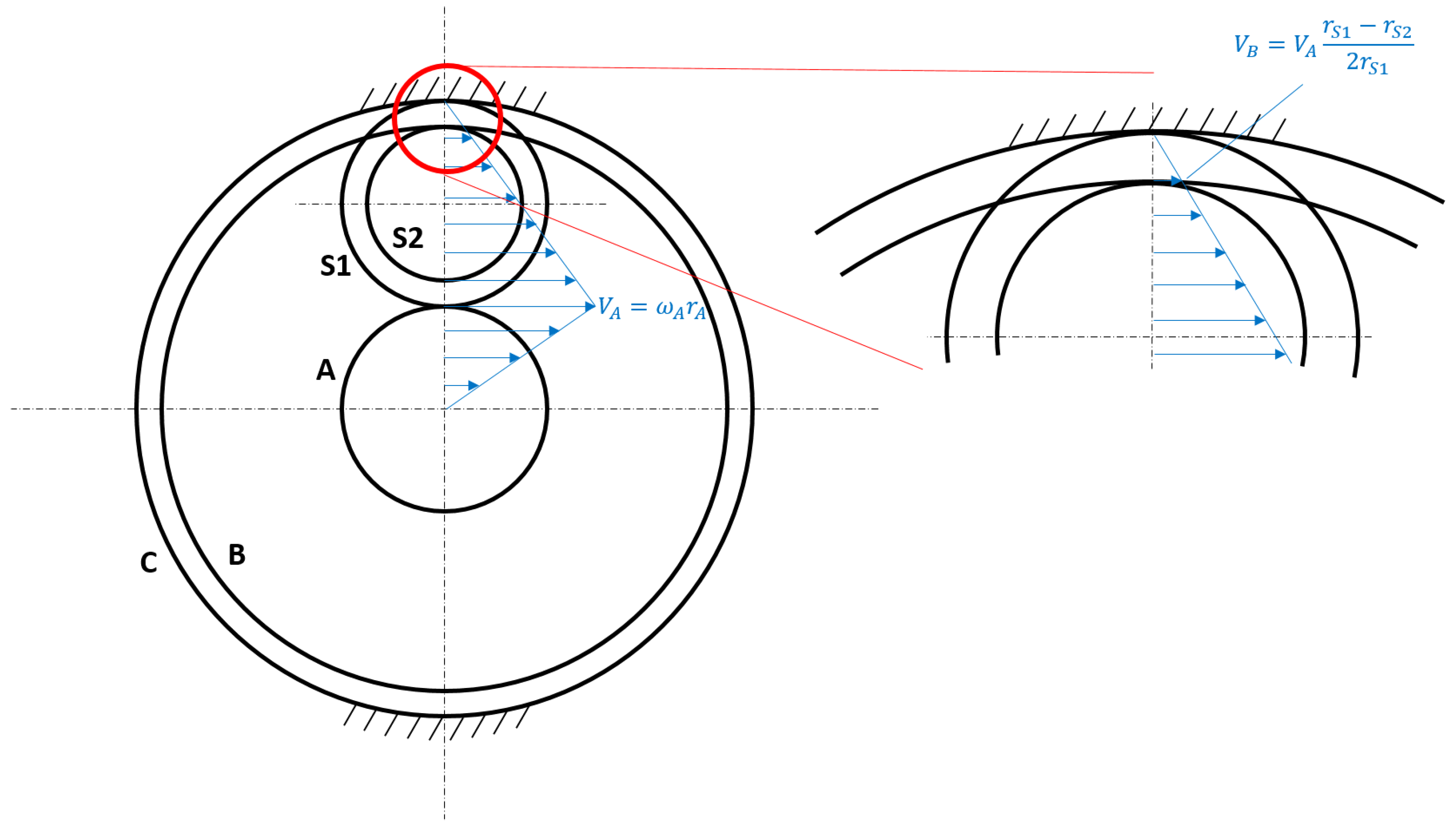
The layout of the planetary gearbox is shown in Figure 2. The input shaft A carries the sun gear of a first planetary stage, with teeth. The ring gear C of this first stage is fixed. The satellites S1 of this first stage have teeth and are integral with those of a second stage, which lacks a sun gear. The satellites of the second stage S2 have teeth and engage with a ring gear B, which is the output of the transmission. The number of degrees of freedom of the planetary gear train can be computed as:
where are the single DoF joints (i.e. the supported axes), are the single DoF joints (i.e., meshings), and are the moving parts, considering a single satellite and the virtual planet carrier.
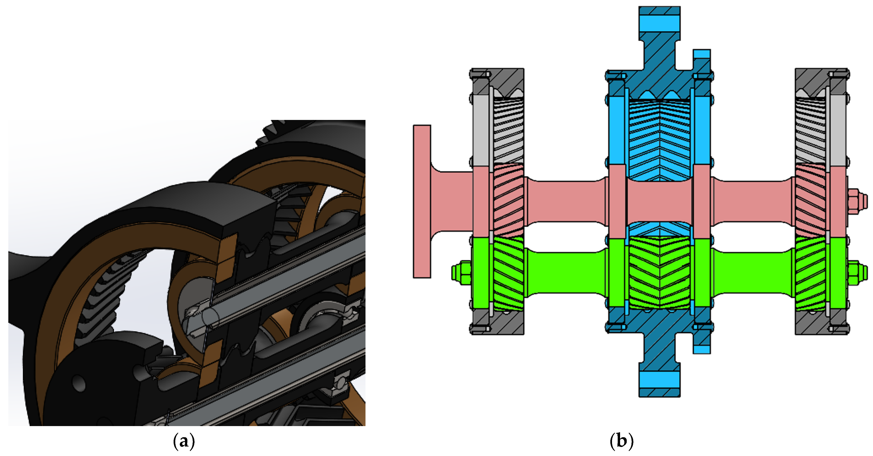
Being , the translation speed of the second stage satellite does not match its peripheral speed. Then, the second stage ring gear B is dragged with a peripheral speed , equal to the residual between the translation and peripheral speed of the satellite (Figure 3). The first planetary stage is mirrored on the opposite side of the output stage in order to balance the forces acting on the satellites. This way, the planet carrier is not needed, since no torque or forces are applied to it [22,24]. The use of rolling rings in parallel of the gears, matching in diameter the primitive circle of the respective wheels, allows us to support radial loads [22], as shown in Figure 4.
The helical teeth of the gears support axial loads in either direction. Specifically, the two first-stage gearings have helical gears with an opposed helix angle, while the output stage features herringbone teeth. As a result, all the shafts are self-supported by gear meshing and rolling rings (provided at least three satellites are present), and no bearings are needed: the system behaves as a combined gear bearing [25]. This translates into a significant reduction in the number of moving parts and a reduction in the local concentrations of contact pressure, with possible advantages in terms of reliability and robustness to large radial loads.
3. Computation of the Gear Ratio
The gear ratio of the transmission can be computed with Willis’ equation. In the reference frame of the (virtual) planet carrier, the transmission ratio from the input A to the output B is:
where Ω is the angular velocity of the planet carrier. Similarly, the transmission ratio between the input A and the ring gears C is:
Imposing that the ring gears C are fixed (), the total gear ratio in a fixed reference is:
The geometrical compatibility of the first planetary stage poses the constraint:
The modulus of the gears is not necessarily constant between the first and second stage. The use of two different moduli can result in a higher reduction ratio and better gear optimization, at the expense of higher manufacturing costs (at least if employing subtractive manufacturing technologies).
Additionally, in a number of practical applications, it is accepted to employ teeth corrections or so that the center distance between the axis of the satellites and that of the two ring gears can be kept constant, while allowing a larger flexibility to the gear ratio. However, for simplicity, we assumed to employ the same modulus on both stages, since a combination of numbers of teeth compatible with our application was found under said assumption. The assumption of constant modulus yields:
This way, Equation (4) can be rearranged as:
A more general expression for the gear ratio, that does not rely on a constant value for the modulus between the two stages, can be derived from the velocity distribution shown in Figure 3. Being and , the gear ratio is:
which is equivalent to Equation (7) for a constant modulus. An additional constraint for the numbers of teeth emerges from the need to place the satellites equally spaced and compensate dynamical loads to reduce vibration:
For an integer k, where n is the number of satellites. Eventually, according to ISO 6336, the minimum number of teeth for gear wheels with normal pressure angle and helix angle is:
for , , , and considering a normal profile with , and no correction (i.e. ). To deal with the limited tolerances allowed by FDM additive manufacturing, we chose a relatively large value of 2 mm for the modulus m, and to limit the maximum number of teeth in the order of 60 to 65, in order to fit an entire wheel in a single print.
With these constraints, the number of teeth were chosen as: , , , , . This results in a gear ratio , which is compatible with the requirements of the EMA test bench. Additionally, the integer gear ratio simplifies the conversion of the encoder readings to the motor shaft for control purposes. Since integer math can be used, the workload for the control electronics is alleviated.
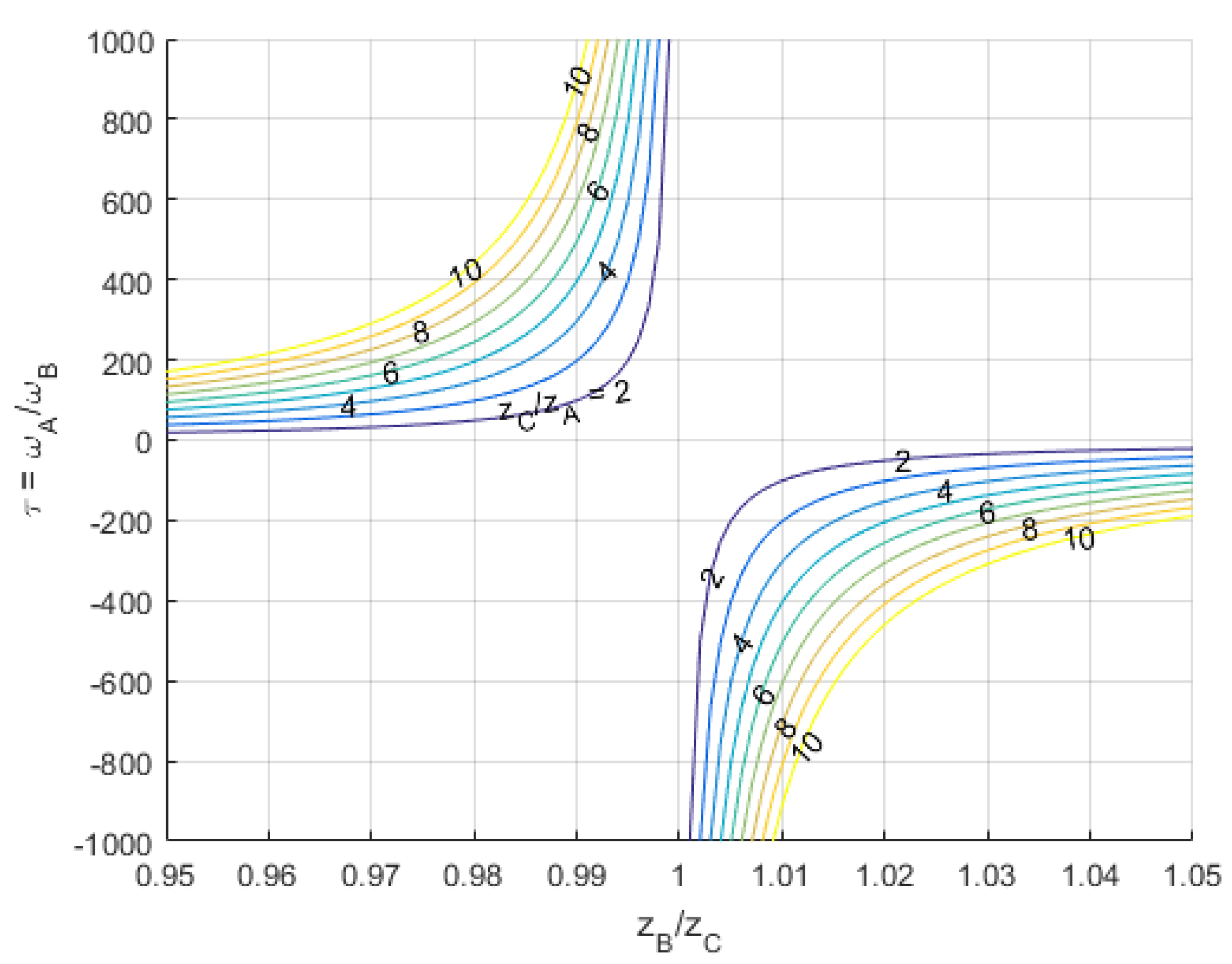
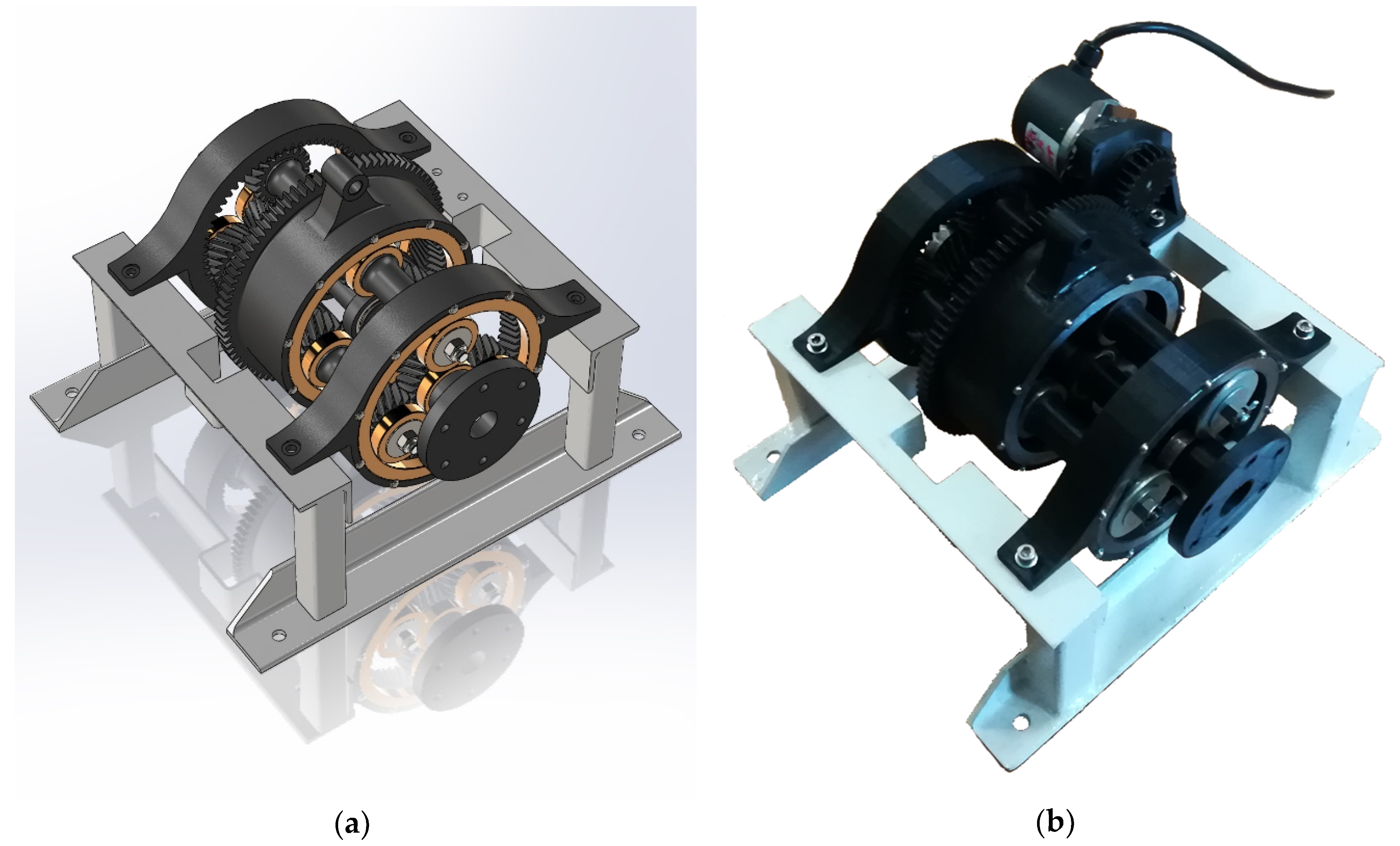
The proposed arrangement for the gearbox allows for reaching high gear ratios with a small form factor. Specifically, if the number of teeth is chosen in a way that , the denominator of the right term of Equation (4) becomes small and the gear ratio increases. For example, modifying the numbers of teeth while still imposing that no wheel has more than 65 teeth, it is possible to reach ratios in excess of 180:1. At the same time, the axial dimension of the gearbox is comparable to two planetary stages, or possibly smaller since there is no planet carrier. Figure 5 shows the relationship between gear ratio and the number of teeth of the wheels, while Figure 6 shows the CAD model and the final realization of the transmission.
4. Comparison with Harmonic Drive
The performance of the proposed architecture appears similar to that of Harmonic Drives [26,27]. Both transmissions allow for reaching high gear ratios within small spaces and are able to transfer high torques thanks to the large number of meshing teeth.
The single meshing of a Harmonic Drive, with tenths of teeth at the same time, is able to provide an almost backlash-free transmission and a good mechanical efficiency. The proposed reducer has two meshing gears connecting the output ring gear to the fixed ring gears, so a relatively small backlash and a good efficiency are expected as well, although the Harmonic Drive may still be better in this regards. Quantitative analyses on backlash and mechanical efficiency are currently in progress and will be the subject for a future study.
As opposed to the Harmonic Drive, the proposed design does not rely on flexible parts for its operation. Therefore, higher stiffness and higher robustness to fatigue damage can be achieved. For the same reason, large preloads (as with those needed to bend in shape the flexspline of a strain wave gearing) are not required. This may result in an advantage in terms of mechanical efficiency in low load condition, as well as a smaller starting torque.
One advantage over the strain wave gearings is the lower number of teeth for a given gear ratio. The chosen combination of teeth achieves a gear ratio of 124:1 with the largest wheel having 63 teeth. The same ratio would require a Harmonic Drive to have, for example, a ring gear with 250 teeth and a flexspline with 248. Although and the larger number of meshing teeth can compensate for the smaller modulus in terms of maximum torque, tolerances must be very tight for the correct operation of the gearing. The lower number of teeth of the proposed gearing can relax this requirement, to the point that a working prototype has been manufactured with a low cost FDM 3d printer.
Another advantage can be found in the lower inertia of the gearing, making it suitable for applications requiring high dynamics, such as servoactuators. The moment of inertia reduced to the input shaft of the proposed planetary gearing has been computed with a simplified model and compared with that of a Harmonic Drive with the same gear ratio and the same radial dimensions. In the following computations, we assumed unit density and unit axial length for both reducers.
The inertia of all wheels have been approximated with that of their primitive cylinder. Considering the planetary gear, the inertia of the input shaft is:
where is the mass of the input shaft and its sun gears. The inertia of the output shaft is:
assuming that its external radius is 20% larger than its primitive radius. It is reduced to the input shaft by dividing it by the square of the transmission ratio . The inertia of satellite gears is computed similarly to the input shaft, and is reduced to the input shaft:
where , , and is the radius of the virtual planet carrier. The same model has been applied to a Harmonic Drive with the same radius and gear ratio of the proposed reducer, considering the wave generator as the input shaft, the flexspline as the output shaft, and treating the rollers as satellites. Three satellites have been considered for the planetary drive, and 20 rollers for the Harmonic Drive. Table 1 shows the comparison in terms of inertia of the two architectures.
In the Harmonic Drive, the wave generator moves at the same speed of the input shaft and has a radius comparable to the whole drive. Conversely, in the proposed compound planetary gearing, only the sun gear moves at the input angular speed. Additionally, the transmission ratio from the input to the virtual planet carrier is in the range of 3 to 5, while the rollers of a Harmonic Drive usually have an angular speed higher than the input shaft. As a result, the total inertia of the proposed reducer is more than one order of magnitude lower than a Harmonic Drive of similar performances.
5. Advantages and Limits of FDM Additive Manufacturing
The design of the whole EMA test bench was carried out making extensive use of FDM additive manufacturing to reduce costs and time for prototyping components. For the same reason, easily available off-the-shelf components were employed where possible. Only the steel rolling rings for the transfer of radial loads were custom produced, since the required tolerances and surface finish were not compatible with additive manufacturing.
The use of FDM 3D printing, similar to any other production technology, must be taken into account starting from the early design phases of a mechanical equipment. This technique offers several advantages over traditional technologies. First, very complex geometries can be dealt with, without additional processes required for production. For this reason, it is possible to design from the beginning parts with structural lightening, stiffening ribs, and articulated three-dimensional geometries, without paying excessive attention to the limitation of required processes. Additionally, the number of parts of an assembly can be greatly reduced, since complex components can be produced in one piece. However, some considerations shall be made regarding the limited capability of FDM to produce cantilevered parts; support structures can be employed sometimes to mitigate this issue, but depending on their placement, removal can be troublesome.
For the presented application, the design of the gear wheels involved special attention, as printing via FDM requires respecting some fundamental constraints. Specifically:
- It is not possible to produce unsupported protruding surfaces for more than a couple millimeters; therefore, it is necessary to redesign the components that have protruding surfaces with dimensions greater than the indicated value which, otherwise, would require the generation of supports
- Especially when using a single nozzle machine (so that support structures are printed with the same material as the workpiece), the use of supports shall be limited to the locations where they can be removed easily, for example, on cavities having at least two opposite sides communicating with the outside, or for sufficiently large protruding surfaces. Supports inside small blind holes shall be avoided.
- The features of the parts, and, in particular, the cavities, must have a dimension large enough not to be filled with excess extruded material; commonly, on low cost printers, this means larger than one or two millimeters.
- Where possible, the inclination of the bottom surfaces must be greater than 60°, in order to avoid the addition of support structures, which are difficult to remove. This aspect shall be taken into account also when determining the orientation to print the parts with.
- The design of pieces must account for an error up to 1% or 2% of the parts dimensions (a value we obtained experimentally). This is due to the thermal shrinking of the part being printed; in fact, the deposited material is affected by the temperature difference between the outlet of the nozzle and the external environment. The effect is mitigated in part by printers with a closed, temperature-controlled chamber. If possible, the design shall accommodate for these uncertainties. Mechanical components requiring higher precision can be corrected in the CAD software to compensate for the shrinkage errors, possibly following a test print.
- Surface finish is very smooth on the bottom face in contact with the print bed. A good finish can be achieved on horizontal and vertical surfaces, while it is worse on inclined faces. Overhanging surfaces are usually prone to delamination and shall be avoided when possible.
However, the deposition plane is heated and allows for limiting the shrinking phenomenon and improving the properties of the finished piece in terms of mechanical resistance and surface finish. The thermal effect, however, must be considered in the phase of resizing the pieces to pass from the nominal measures of the CAD file to the measures for the printing phase.
Additive manufacturing allowed containing costs for prototyping the planetary gearbox; some parts would have been troublesome to produce with traditional technologies, and the cost for a single prototype would have been very high without the benefit of scale production. This is the case, for example, of the output ring gear of the transmission; it is an internal gear wheel with herringbone teeth, with rolling rings on the two sides, and additional features on the outside surface (such as fittings for other components and the external gear for the encoder shaft). The production via traditional machining would have required either the redesign of the part to split it into several components, or the use of expensive multi-axis CNC machines.
FDM additive manufacturing also faces some limitations when employed to produce functional mechanical components. First, the mechanical properties of most printable materials are poor; the tensile strength of Acrylonitrile-Butadiene-Styrene (ABS) and PolyLactic Acid (PLA) is in the order of 30 MPa, with an elastic modulus of 1.2 to 3.5 GPa. Those properties refer to the base material, and are affected by the printing process [28,29]. Surface hardness is low as well, and high contact pressure in coupling between components shall be avoided.
Additionally, some lubricants commonly employed on metal parts are not chemically compatible with printable polymers. Little literature is available regarding the compatibility of lubricants with polymers for FDM; however, it appears that most mineral and synthetic oils and greases tend to attack PLA and ABS [30]. The immersion of a PLA sample in silicone grease for a week did not significantly modify its mechanical properties. Therefore, we decided to employ this as a lubricant for the gearbox.
6. Discussion
A planetary gear reducer was designed and manufactured for the EMA test bench. The chosen design offers performances comparable to a Harmonic Drive in terms of compactness, high gear ratio, and low backlash. The lack of flexible components results in higher stiffness and more robustness to fatigue damage, while the two-stage configuration achieves a high gear ratio without the need for wheels with a large number of small teeth and allows relaxing tolerance constraints. Additional advantages of the proposed configuration are the low inertia, making it suitable for demanding, high dynamics applications, and the bearingless construction with a reduced number of moving parts. As a result, good robustness to high torque and high radial loads is achieved.
Most components of the assembly were produced with FDM, in order to lower costs and quickly manufacture a functional prototype. As a result, we obtained several lessons learned for prototyping functional mechanical parts with low cost additive manufacturing techniques, specifically FDM 3d printing with PLA. The limits of materials in terms of poor mechanical properties and chemical compatibility with lubricants were addressed, and the geometry of components was defined accounting for the capabilities of the selected production technology.
Future work will include a quantitative evaluation of friction and mechanical efficiency, both in aiding and opposing load conditions, and the comparison with experimental results.
Author Contributions
Conceptualization, P.C.B.; methodology, P.C.B. and G.R.; software, P.C.B. and G.R.; validation, P.C.B., G.R. and M.D.L.D.V.; formal analysis, P.C.B., G.R. and M.D.L.D.V.; investigation, G.R.; resources, G.R.; data curation, P.C.B. and M.D.L.D.V.; writing—original draft preparation, G.R.; writing—review and editing, P.C.B. and M.D.L.D.V.; visualization, P.C.B.; supervision, P.M.; project administration, P.M.; funding acquisition, P.M. All authors have read and agreed to the published version of the manuscript.
Funding
This research was supported by the PhD Scholarship awarded to Pier Carlo Berri under the PhD program at Politecnico di Torino.
Acknowledgments
The authors wish to thank ASSOCAM Scuola Camerana for the supply of the machined rolling rings for the planetary gearbox.
Conflicts of Interest
The authors declare no conflict of interest.
References
- Pease, W. An automatic machine tool. Sci. Am. 1952, 187, 101–115. [Google Scholar] [CrossRef]
- Makely, W. Numbers take control: NC machines. Cut. Tool Eng. 2005, 57, 4–5. [Google Scholar]
- Qiao, G.; Liu, G.; Shi, Z.; Wang, Y.; Ma, S.; Lim, T.C. A review of electromechanical actuators for More/All Electric aircraft systems. Proc. Inst. Mech. Eng. Part C J. Mech. Eng. Sci. 2017, 232, 4128–4151. [Google Scholar] [CrossRef] [Green Version]
- Rubertus, D.P.; Hunter, L.D.; Cecere, G.J. Electromechanical Actuation technology for the all-electric aircraft. IEEE Trans. Aerosp. Electron. Syst. 1984, 20, 243–249. [Google Scholar] [CrossRef]
- Budinger, M.; Liscouët, J.; Hospital, F.; Maré, J.C. Estimation models for the preliminary design of electromechanical actuators. Proc. Inst. Mech. Eng. Part G J. Aerosp. Eng. 2012, 226, 243–259. [Google Scholar] [CrossRef] [Green Version]
- Budinger, M.; Reysset, A.; El Halabi, T.; Vasiliu, C.; Maré, J.C. Optimal preliminary design of electromechanical actuators. Proc. Inst. Mech. Eng. Part G J. Aerosp. Eng. 2013, 228, 1598–1616. [Google Scholar] [CrossRef] [Green Version]
- Fu, J.; Maré, J.C.; Fu, Y. Modelling and simulation of flight control electromechanical actuators with special focus on model architecting, multidisciplinary effects and power flows. Chin. J. Aeronaut. 2017, 30, 47–65. [Google Scholar] [CrossRef] [Green Version]
- Quigley, R. More electric aircraft. In Proceedings of the Eighth Annual IEEE Applied Power Electronics Conference and Exposition, San Diego, CA, USA, 7–11 March 1993. [Google Scholar]
- Howse, M. All-electric aircraft. Power Eng. 2003, 17, 35. [Google Scholar] [CrossRef]
- Hussien, M. Power electronics application for more electric aircraft. Recent Adv. Aircr. Technol. InTech 2012, 14, 289–308. [Google Scholar]
- Deng, Y.; Foo, S.Y.; Bhattacharya, I. Regenerative electric power for more electric aircraft. In Proceedings of the IEEE southeastcon 2014, Lexington, KY, USA, 13–16 March 2014. [Google Scholar]
- Balaban, E.; Bansal, P.; Stoelting, P.; Saxena, A.; Goebel, K.F.; Curran, S. A diagnostic approach for electro-mechanical actuators in aerospace systems. In Proceedings of the 2009 IEEE Aerospace conference, Big Sky, MT, USA, 7–14 March 2009. [Google Scholar]
- Balaban, E.; Saxena, A.; Goebel, K.F.; Byington, C.S.; Bharadwaj, S.P.; Smith, M. Experimental data collection and modeling for nominal and fault conditions on electro-mechanical actuators. In Proceedings of the Annual Conference of the Prognostics and Health Management Society, San Diego, CA, USA, 7–14 March 2009. [Google Scholar]
- Balaban, E.; Saxena, A.; Narasimhan, S.; Roychoudhury, I.; Goebel, K.F.; Koopmans, M. Airborne electro-mechanical actuator test stand for development of prognostic health management systems. In Proceedings of the Annual Conference of the Prognostics and Health Management Society, Portland, OR, USA, 10–16 October 2010. [Google Scholar]
- Vachtsevanos, G.; Lewis, F.; Roemer, M.; Hess, A.; Wu, B. Intelligent Fault Diagnosis and Prognosis for Engineering Systems; John Wiley & Sons, Inc.: Hoboken, NJ, USA, 2006. [Google Scholar]
- De Martin, A.; Jacazio, G.; Vachtsevanos, G. Windings Fault Detection and Prognosis in Electro-Mechanical Flight Control Actuators Operating in Active-Active Configuration. Available online: https://iris.polito.it/retrieve/handle/11583/2686857/169661/2017_ASTIB-IJPHM%288%29.pdf (accessed on 10 September 2019).
- Nesci, A.; De Martin, A.; Jacazio, G.; Sorli, M. Detection and prognosis of propagating faults in flight control actuators for helicopters. Aerospace 2020, 7, 20. [Google Scholar] [CrossRef] [Green Version]
- Lei, Y.; Lin, J.; Zuo, M.J.; He, Z. Condition monitoring and fault diagnosis of planetary gearboxes: A review. Meas. J. Int. Meas. Confed. 2014, 48, 292–305. [Google Scholar] [CrossRef]
- Wang, T.; Han, Q.; Chu, F.; Feng, Z. Vibration based condition monitoring and fault diagnosis of wind turbine planetary gearbox: A review. Mech. Syst. Signal Process. 2019, 126, 662–685. [Google Scholar] [CrossRef]
- Djeziri, M.A.; Benmoussa, S.; Benbouzid, M.E. Data-driven approach augmented in simulation for robust fault prognosis. Eng. Appl. Artif. Intell. 2019, 86, 154–164. [Google Scholar] [CrossRef]
- Djeziri, M.; Benmoussa, S.; Sanchez, R. Hybrid method for remaining useful life prediction in wind turbine systems. Renew. Energy 2018, 116, 173–187. [Google Scholar] [CrossRef]
- Brassitos, E.; Jalili, N. Design and development of a compact high-torque robotic actuator for space mechanisms. J. Mech. Robot. 2017, 9, 061002. [Google Scholar] [CrossRef] [Green Version]
- Berri, P.C.; Dalla Vedova, M.D.L.; Maggiore, P.; Manuello Bertetto, A. Simplified models for mechanical transmission efficiency with opposing and aiding loads. Int. J. Mech. Control 2019, 20, 135–139. [Google Scholar]
- Kapelevich, A. High gear ratio epicyclic drives analysis. Gear Technol. 2014, 3, 62–67. [Google Scholar]
- Sheyko, S. Gear bearings and fine mechanical applications of them. Adv. Eng. Forum 2017, 23, 104–113. [Google Scholar] [CrossRef]
- Zou, C.; Tao, T.; Jiang, G.; Mei, X.; Wu, J. A harmonic drive model considering geometry and internal interaction. Proc. Inst. Mech. Eng. Part C J. Mech. Eng. Sci. 2015, 231, 4. [Google Scholar] [CrossRef]
- Li, Z.; Melek, W.W.; Clark, C. Decentralized robust control of robot manipulators with harmonic drive transmission and application to modular and reconfigurable serial arms. Robotica 2009, 27, 291–302. [Google Scholar] [CrossRef] [Green Version]
- Brischetto, S.; Torre, R.; Ferro, C.G. Experimental evaluation of mechanical properties and machine process in fused deposition modelling printed polymeric elements. Adv. Intell. Syst. Comput. 2020, 975, 377–389. [Google Scholar] [CrossRef]
- Brischetto, S.; Ferro, C.G.; Torre, R.; Maggiore, P. 3D FDM production and mechanical behavior of polymeric sandwich specimens embedding classical and honeycomb cores. Curved Layer. Struct. 2018, 5, 80–94. [Google Scholar] [CrossRef]
- Cavestri, R.C. Compatibility of refrigerants and lubricants with engineering plastics. In Final Report Prepared for the Air-Conditioning and Refrigeration Technology Institute Under ARTI MCLR Project Number 650-50600; Imagination Resources, Inc.: Dublin, OH, USA, 1 December 1993. [Google Scholar]
Figure 1.
Layout of the Electromechanical Actuator (EMA) test bench.

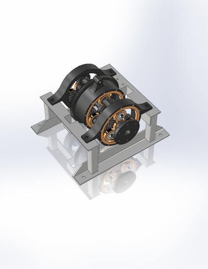
Figure 2.
Layout of the gearing.

Figure 3.
Velocity distribution.

Figure 4.
(a) Detail of the metal rolling rings employed to support radial loads; (b) partial cross-section of the gearbox, highlighting the herringbone and helical teeth. Note that the spacers between the stages are intended only to ease the installation of sensors on the EMA test bench; a production version would not need them and would have about half the axial length.

Figure 5.
Gear ratio as a function of the number of teeth.

Figure 6.
(a) Render of the CAD model of the transmission; (b) final realization of the assembly.


Table 1.
Moment of inertia of planetary gearbox and Harmonic Drive.
| Planetary Gearbox | Harmonic Drive | |||
|---|---|---|---|---|
| Self Inertia [g mm2] | Inertia Reduced to A [g mm2] | Self Inertia [g mm2] | Inertia Reduced to A [g mm2] | |
| Input shaft | 4.58 × 10² | 4.58 × 10² | 1.79 × 10⁴ | 1.79 × 10⁴ |
| Satellite/Roller | 5.57 × 10² | 3 × 4.30 × 102 | 4.87 × 10⁻¹ | 20 × 78.2 |
| Output shaft | 2.49 × 10⁴ | 1.62 | 5.88 × 10³ | 3.83 × 10⁻¹ |
| Total | 1.75 × 10³ | 1.94 × 10⁴ | ||
© 2020 by the authors. Licensee MDPI, Basel, Switzerland. This article is an open access article distributed under the terms and conditions of the Creative Commons Attribution (CC BY) license (http://creativecommons.org/licenses/by/4.0/).
Share and Cite
MDPI and ACS Style
Berri, P.C.; Dalla Vedova, M.D.L.; Maggiore, P.; Riva, G. Design and Development of a Planetary Gearbox for Electromechanical Actuator Test Bench through Additive Manufacturing. Actuators 2020, 9, 35. https://doi.org/10.3390/act9020035
AMA Style
Berri PC, Dalla Vedova MDL, Maggiore P, Riva G. Design and Development of a Planetary Gearbox for Electromechanical Actuator Test Bench through Additive Manufacturing. Actuators. 2020; 9(2):35. https://doi.org/10.3390/act9020035
Chicago/Turabian StyleBerri, Pier Carlo, Matteo D. L. Dalla Vedova, Paolo Maggiore, and Guido Riva. 2020. "Design and Development of a Planetary Gearbox for Electromechanical Actuator Test Bench through Additive Manufacturing" Actuators 9, no. 2: 35. https://doi.org/10.3390/act9020035
Note that from the first issue of 2016, this journal uses article numbers instead of page numbers. See further details here.