1. Introduction
In vehicle dynamics, controlled mechanical suspension systems are used to isolate passengers from harmful vibrations to health, provoked commonly by uncertain irregular road disturbance forces, and contribute to achieve satisfactory handling performance indicators like a suitable contact between the tire and road surface and stable vehicle guidance. Conventional or passive suspension systems can only obtain a limited performance for both ride comfort and vehicle handling for stable operation conditions and specific classes of vehicles due to physical constraints. Active control mechanisms can achieve better dynamic performance by applying controlled actuation forces, according to online system motion information provides from sensors located at properly selected positions in the vehicle [
1,
2,
3,
4,
5,
6]. Diverse control design methodologies have been applied for active suspension systems where real-time information of system variables and uncertainty could be necessary to achieve an optimal reduction of exogenous vibrations (see [
7,
8,
9,
10,
11,
12] and references therein). Active control forces can be implemented by hydraulic, pneumatic or electromagnetic actuators commonly located in parallel with a spring and a damper [
6]. In this sense, electromagnetic actuators are more environmentally friendly, and exhibit a response much faster than hydraulic dampers [
11]. An energy flow analysis of an electromagnetic active quarter-vehicle suspension system has been discussed in [
12]. Moreover, several configurations of magnetic actuation mechanisms have been proposed in [
11,
13,
14,
15,
16]. A spherical air bearing positioning system using electromagnetic actuators has been also developed in [
17]. Other important applications of magnetic suspension systems have been reported in [
18,
19,
20]. Hence, active suspension systems using electromagnetic actuators represent a feasible and efficient alternative for undesirable vibration attenuation and isolation.
Thus, efficient vibration suppression levels can be obtained by suitably and actively compensating excitation forces generated by vehicle motion on irregular road surfaces. Indeed, information about real-time disturbance (signal) forces can be employed for synthesis of closed-loop control systems to get a very good dynamic performance in active vibration control of flexible mechanical systems. Variable weight of the passengers and uncertain parametric variations of the suspension components due to fatigue, wear and natural aging represent other unknown possible perturbations that could result in a dynamic performance degradation [
21]. Consequently, important estimation techniques of system parameters have been introduced in the literature [
22,
23,
24]. An identification method of boundary forces in beam-like structures using a derivative estimator has been introduced in [
25]. In this regard, algebraic parametric identification methods have been also proposed for online reconstruction of unknown excitation forces [
26,
27,
28]. Bounded disturbances have been also locally modelled by certain order Taylor polynomials for synthesis of asymptotic extended state observers for robust and efficient trajectory tracking control tasks on nonlinear magnetic suspension systems [
19,
20] and active nonlinear vibration suppression on mechanical systems [
29].
On the other hand, time derivatives of some system variables (e.g., velocity and acceleration) could also be required for implementation of active vibration control schemes. In fact, error signal differentiation is demanded in classical Proportional-Integral-Derivative (PID) control which is applied in many industrial engineering systems. In this regard, a PID controller for a variable engine valve train with an electromagnetic actuator has been designed in [
15]. An inner loop PID force controller for an electrohydraulic actuator in an active suspension system for camera stabilization has been used in [
30]. Similarly, in [
31] velocity signals are required for the desired hydraulic force of the actuator in a quarter car active suspension. PID control has been also implemented in an active vibration isolation system with an active dynamic vibration absorber in [
32]. Furthermore, velocity signal feedback is commonly employed to inject damping to some flexible mechanical structure to attenuate undesirable oscillations of certain vibration modes. Signal derivatives can be used to reconstruct disturbance forces affecting a vibration mechanical system as well. In differentially flat dynamic systems, control and state variables can be parameterized algebraically in terms of flat output signals and a finite number of their time derivatives [
33]. State vector estimation is commonly based on asymptotic observers designed for specific dynamical systems when accurate analytic models are available. In practice, differentiation of signals is also performed by real-time numerical computations from samples of the available output signals. However, numerical differentiation could deteriorate the efficiency and robustness of system identification or control when measurements are corrupted by noise.
Signal differentiation can be conveniently used for parametric identification purposes as well. A method of determining the parameters of a multicomponent RLC-two-terminal network using differentiation of signals has been proposed in [
34]. In [
35] a differentiator for estimating the power system frequency, monitoring and controlling the operational status of the grid as well as synchronization of electronic power converters has been introduced. An algorithm to detect and locate a leak in a plastic pipeline subject to different operating conditions has been proposed in [
36]. The algorithm is based on a differentiation approach for the state variables and leak parameters estimation. In [
37], it has been proposed a methodology to evaluate the power quality state estimation by using enhanced numerical differentiation, which obtains the periodic steady state solution of a power network. In [
38] an asymptotic differentiation technique of signals for angular acceleration estimation for controlled DC motors has been proposed.
This paper constitutes an extension of previous contributions of the authors to the online estimation problem of unknown or unmeasurable signals in controlled vibrating mechanical systems (see, [
38,
39,
40] and references therein). An online estimation perspective of disturbances for an active vehicle suspension system is proposed. Unknown disturbances induced by irregular road surfaces are algebraically computed by applying a recent signal differentiation technique, which requires position measurements solely. Estimates of disturbances and time derivatives of signals are used for differential flatness-based control implementation for active perturbation suppression on quarter-vehicle active suspension systems. Active control forces can be implemented by electromagnetic or hydraulic actuators. The signal differentiation algorithm is independent of mathematical models of specific vibrating systems and actuator dynamics. In this fashion, the signal differentiation can be directly implemented on diverse configuration of vehicle suspensions and other applications of magnetic actuators where time derivatives are required. Computer simulation results confirm the effectiveness of the real-time estimation of unavailable signals. A satisfactory level of forced vibration attenuation is verified. Hence, analytical and numerical results evidence a very good efficacy of the presented disturbance signal estimation method to be used like an alternative in active vibration control implementations to suppress forced oscillations in differential flat vibrating mechanical systems.
2. An Actively Controlled Vehicle Suspension System
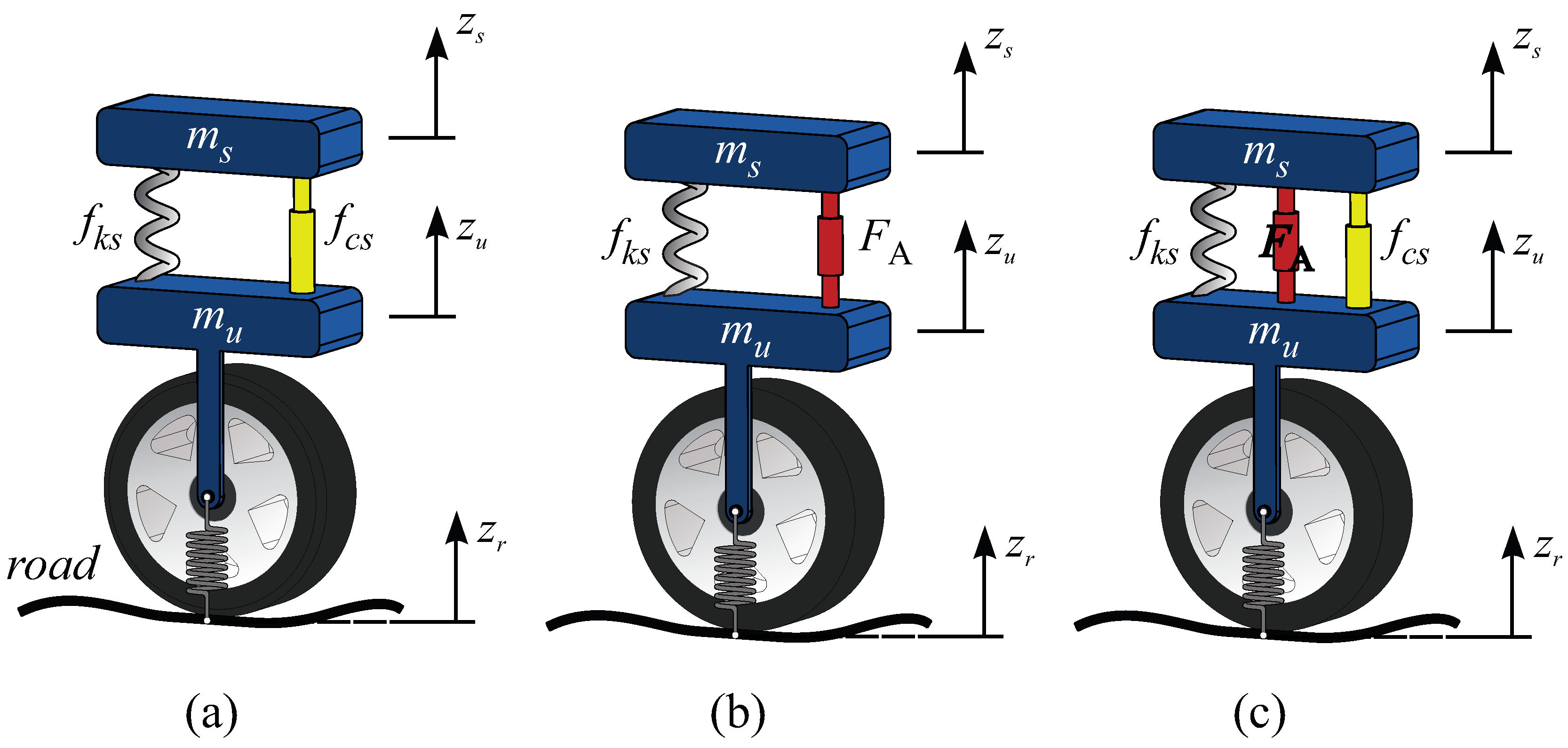
Consider the active suspension system of a quarter vehicle depicted schematically in
Figure 1. Three possible configurations for a passive or active vehicle suspension system are depicted. Active control forces
can be applied by electromagnetic or hydraulic actuators.
The standard mathematical model of this controlled dynamic system is described by the set of coupled differential Equations [
7]
where the sprung mass
represents the mass of the car-body part, the unsprung mass
denotes the mass of the assembly of the axle and wheel,
is the damper coefficient of suspension,
and
are the spring coefficients of the suspension and tire, respectively. The generalized coordinates are the displacements of both masses
and
. Furthermore,
stands for completely unknown disturbance displacements due to irregular road surfaces and
u is the control force input provided by some electromagnetic or hydraulic actuator.
The mathematical model (
1) also admits the state space representation
with position and velocity state variables
,
,
and
.
The active suspension system (
2) exhibits the structural property of differential flatness, which is equivalent to controllability property. Therefore, system variables can be expressed as algebraic formulas in terms of some flat output variable and a finite number of its time derivatives [
33]. Then, the vehicle suspension system also presents the observability property with respect to the flat output. A flat output variable
y can be obtained from the controllability matrix, which is given by [
7]
Therefore, system variables can be expressed by the differential algebraic formulas
Equations (
3) and (
4) yields the transformed equivalent dynamic model
with
,
,
,
, and positive parameters,
,
, given by
Disturbances
, induced by uncertain road surfaces and affecting the transformed system (
5), are described as
A control law based on damping injection and rejection of disturbances
can be then synthesised thanks to the differential flatness property as follows
Notice that parametric uncertainties could be considered into the disturbance signal
as well. Another active vibration control scheme based on differential flatness is given by
with
where
is an auxiliary control input specified to get a prescribed closed-loop dynamic performance for the vehicle suspension system.
Consequently, the closed-loop system dynamics is described by
where the control design parameters,
,
, should be selected such as the characteristic polynomial associated with Equation (
11)
be a Hurwitz (stable) polynomial. Hence, it results in an exponentially asymptotically stable equilibrium point,
.
On the other hand, note that from Equation (
4) the flat output
y and its derivatives up to third order can be algebraically computed from state variables and disturbance
:
Thus, differential flatness-based controllers (
8) and (
9) represents alternatives of solution to the active suppression problem of disturbances for operating scenarios where system parameters are accurately known as well as measurements of state variables and profiles of unknown irregular road surfaces can be performed.
Otherwise, time derivatives of the flat output can be also estimated from position measurements. Moreover, from expressions (
13) of the flat output
y and its second time derivative:
unknown disturbances
can be algebraically computed as follows
On the other side, this paper deals with situations where information of flat output signals is only admissible to actively attenuate forced vibrations induced by unknown irregular road surfaces, due possibly to reduction in implementation costs. In the next section it is described a signal differentiation approach to get approximate derivatives for some possibly controlled stable dynamical system [
38]. Notice that acceleration signals are also employed in a huge set of active vibration control applications.
3. Polynomial Signal Differentiation
First of all, we have considered the operating scenario where a linear or nonlinear mathematical model of some specific dynamic system could be unavailable for estimation of velocity signals. In this fashion, the differentiation technique can be applied for any vibrating mechanical system where some time derivatives of measurable signals are required. In this regard, active control based on injection of dynamic damping for attenuation of harmful oscillations represents an alternative choice [
26]. Indeed, free-model differentiation can be used for diverse applications of control and estimation, where independence of detailed and specific analytical mathematical models is demanded. Certainly, for situations where detailed and accurate mathematical models, including system parameters and disturbances, are available, the synthesis of well-known asymptotic state observers based on these analytic models is an excellent choice. In this sense, for the sake of completeness, consider the
n-th order differentially flat-transformed dynamic system
where it is assumed that system parameters
,
, the control input gain
and disturbances
are completely known. Then, the following asymptotic state observer for estimation of time derivatives of the measurable flat output signal
can be directly synthesized:
where the notation
stands for estimated signal.
Thence the estimation error dynamics is described as
with
. Therefore, by choosing the observer gains
so that the characteristic polynomial of the estimation error dynamics (
18) is a Hurwitz polynomial, we have
On the other hand, for situations where time derivatives of the output signal
, system parameters and control inputs are available, disturbances
affecting the differentially flat system dynamics can be algebraically computed as follows
From another online estimation perspective to avoid dependence on system parameters and disturbances, the synthesis of the signal differentiation scheme with respect to time is based on a local approximation into a sufficiently small time window of some possibly controlled bounded signal
around
by a family of Taylor polynomials of
r-th degree as
where coefficients
are assumed to be unknown as well. Online estimation methods of signal parameters can be also developed [
40], including amplitude, damping, frequency and phase parameters [
41]. An interesting method based on computations of polynomial coefficients by repeated integrations to approximate the original signal derivative has been proposed in [
42]. Nevertheless, real-time parametric estimations and continuous resettings are unnecessary in the signal differentiation method described in the present work.
A low-pass filter
can be additionally implemented to the polynomial output signal to attenuate high frequency oscillating disturbances as follows
The polynomial signal
(
21) can be then reconstructed by solutions of the dynamical system
where
,
,
,
…,
, and
is considered as an unknown bounded perturbation signal including the influence of high frequency noise and small residual terms of the truncated Taylor polynomial expansion (
21) (see [
38]). Moreover, we have assumed that
j-th order time derivatives of the measurable output signal
are uniformly absolutely bounded, i.e.,
,
, where
stands for positive constants.
Hence, from Equations (
23) we propose the following state observer for asymptotic estimation of some time derivatives of the signal
:
which only uses information of the filtered output signal
(see [
38] and references therein).
The estimation error dynamics is then governed by
which is completely independent of any coefficients
of the Taylor polynomial expansion of the output signal
and unknown initial conditions. Here,
,
,
. Notice that, estimator gains should be properly selected in order to have a stable characteristic polynomial for the observer-based closed-loop system dynamics, i.e., all its roots lying in the open left half of the complex plane. Additionally, the estimation dynamics should be sufficiently fast with respect to disturbances to get estimates opportunely.
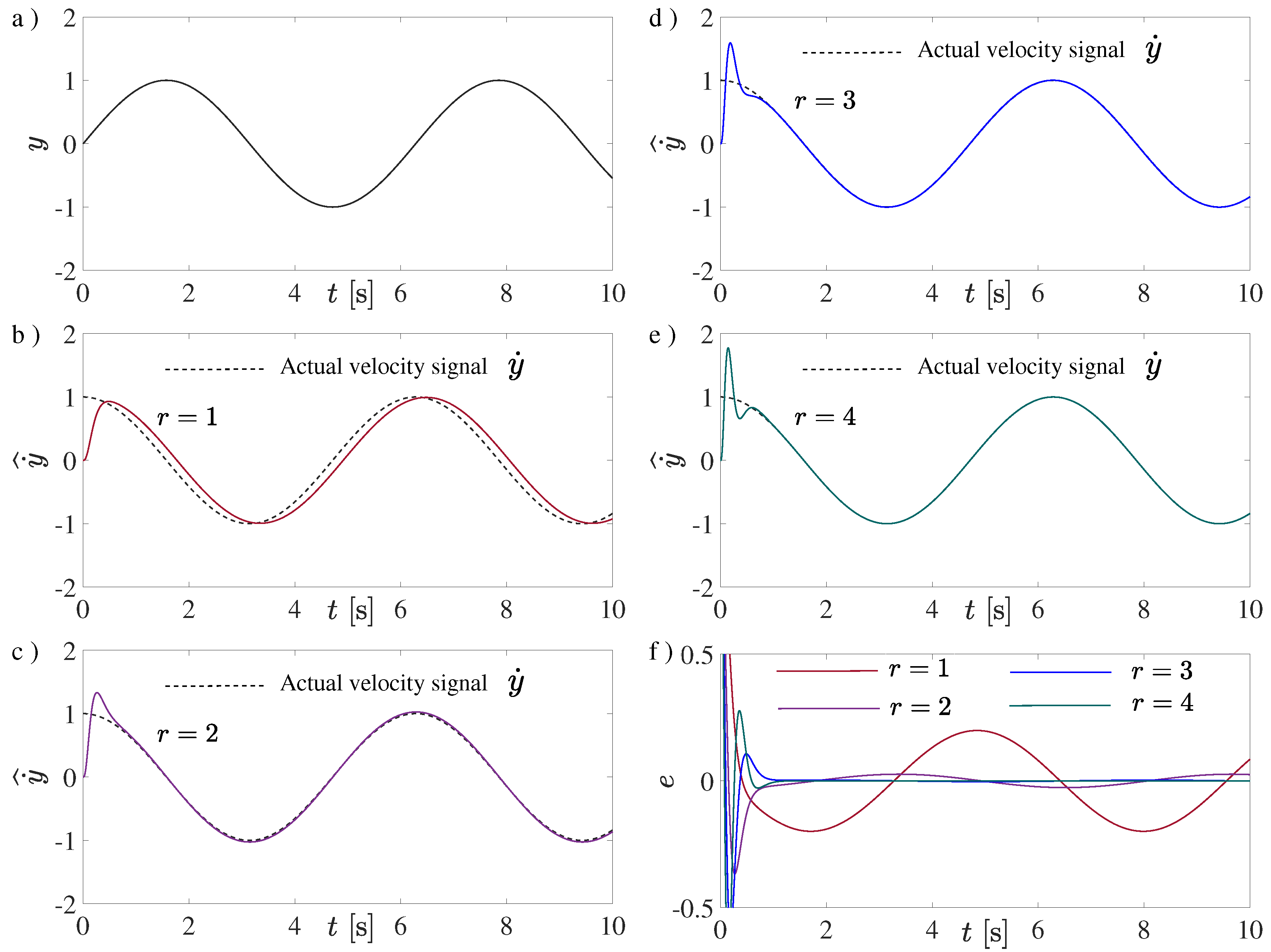
Effectiveness of the polynomial differentiation was also verified numerically using different order numbers for the harmonic output signal
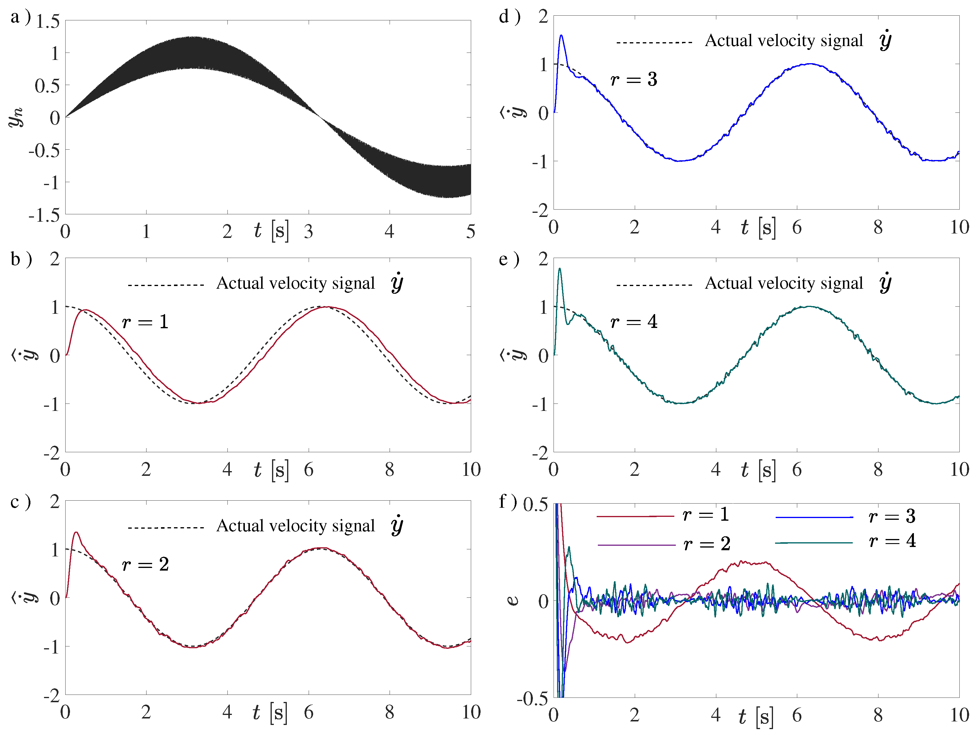
Figure 2 depicts the online estimation of the velocity signal using Taylor polynomial expansions up to fourth order. It can be observed that the velocity reconstruction of the oscillating signal is systematically improved when the order number is increased. The effectiveness of the velocity signal estimation under reasonable measurement noise has been tested as well. In
Figure 3, the satisfactory performance of the velocity estimation based on polynomial series is confirmed for scenarios where the output signal is contaminated with undesirable small additive noise as follows
Here,
denotes stochastic noise consisting of computer-generated random variables with rectangular distribution in the interval
and
is the noisy output signal depicted in
Figure 3a, which is used now for online velocity estimation purposes. Nevertheless, for operational scenarios with important noise levels, some low-pass filter should be previously applied to measured signals. In this context, a pure integration chain can be implemented like a low-pass filter to attenuate high frequency noise (see [
43] and references therein). Computer simulations were performed using fifth-order Runge-Kutta
methods with a fixed small time step of 1 ms. Estimation gains were selected using the following Hurwitz polynomial for the error dynamics (
25):
with
s
.
4. Simulation Results
In this section, some computer simulations are described to show the effectiveness of the online estimation of irregular road disturbance trajectories based on signal differentiation and differential flatness. Performance of the active vibration control scheme (
9) for forced vibration attenuation on a quarter-vehicle suspension system was also tested. The vehicle suspension system is characterized by the set of parameters described in
Table 1 [
9].
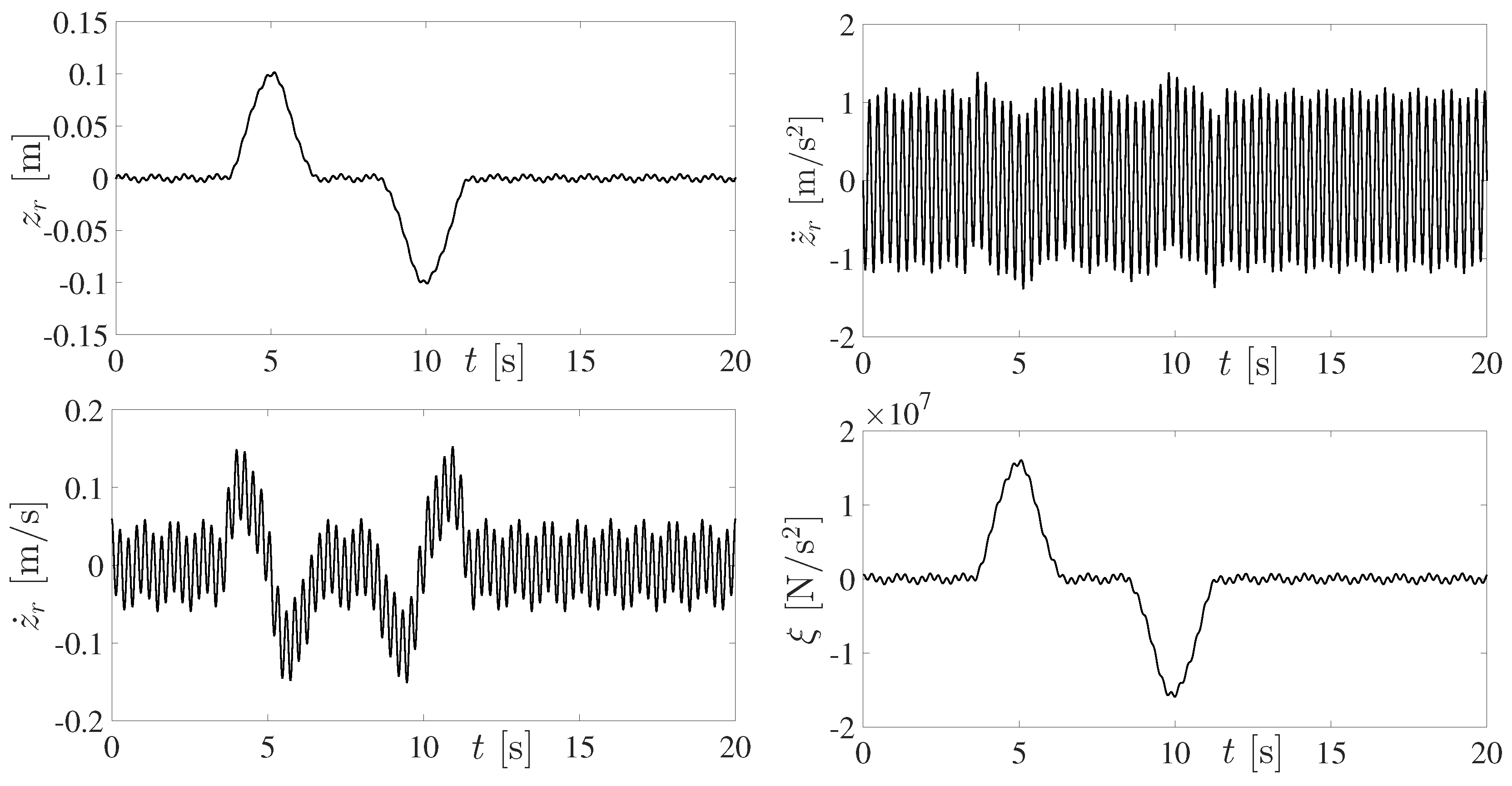
Time-varying disturbance trajectories inducing uncomfort vibrations on the vehicle dynamics are depicted in
Figure 4. Uncertain exogenous motion excitations due to irregular road surfaces are generated by Equation (
29) [
10]. Disturbance signals
affecting to the differentially flat suspension system are described by Equation (
7).
with polynomial and harmonic disturbance components
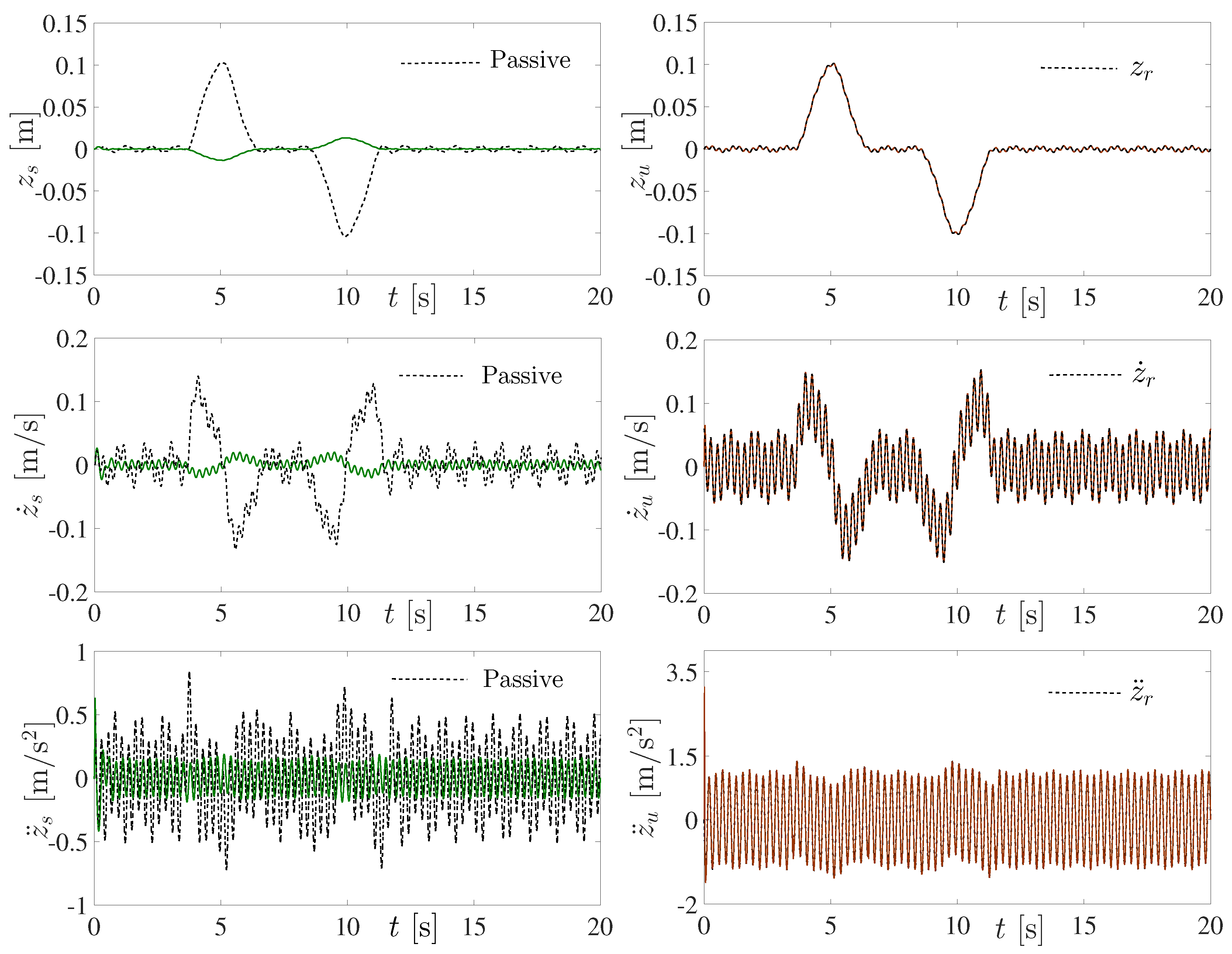
Responses of the passive suspension system are displayed in
Figure 5. A reasonable and expected performance of the passive suspension system for forced vibration attenuation on the car body (unsprung mass) is shown. High amplitudes of displacement, velocity and acceleration signals of the body car are evident. In addition, one can observe that motion of the unsprung mass of the wheel and tire tracks the irregular road trajectories.
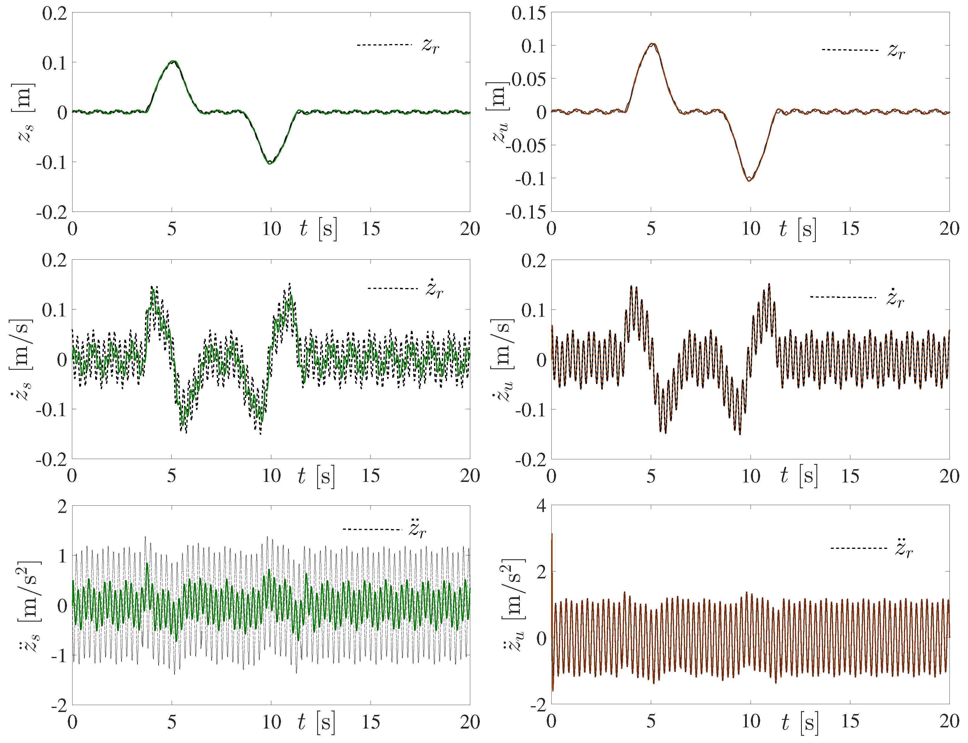
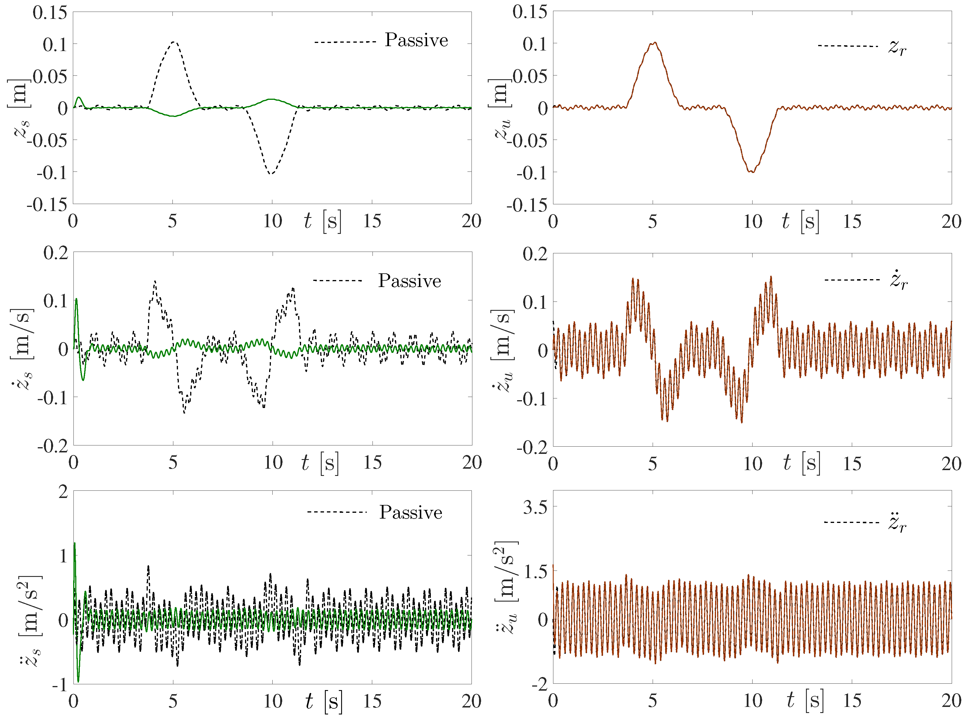
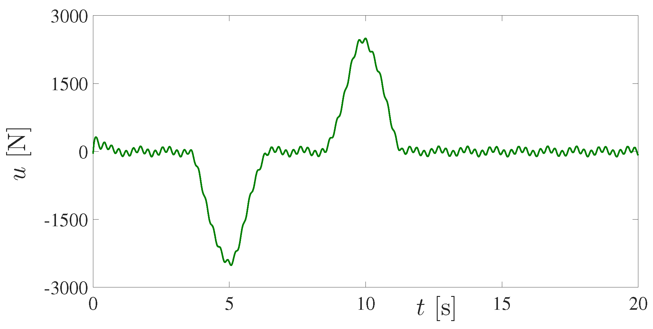
On the other hand, a better performance of the proposed active vibration control scheme for uncertain forced vibration attenuation is confirmed in
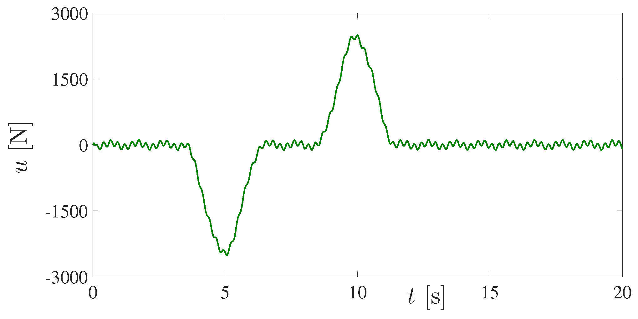
Figure 6. Undesirable oscillations of displacement, velocity and acceleration signals of the body car are significatively reduced. Moreover, a good contact between tire and road to provide guidance along the track is also achieved. The active control force applied to the vehicle suspension system is shown in
Figure 7. The control gains were chosen to have the closed-loop characteristic polynomial
with
rad/s and
.
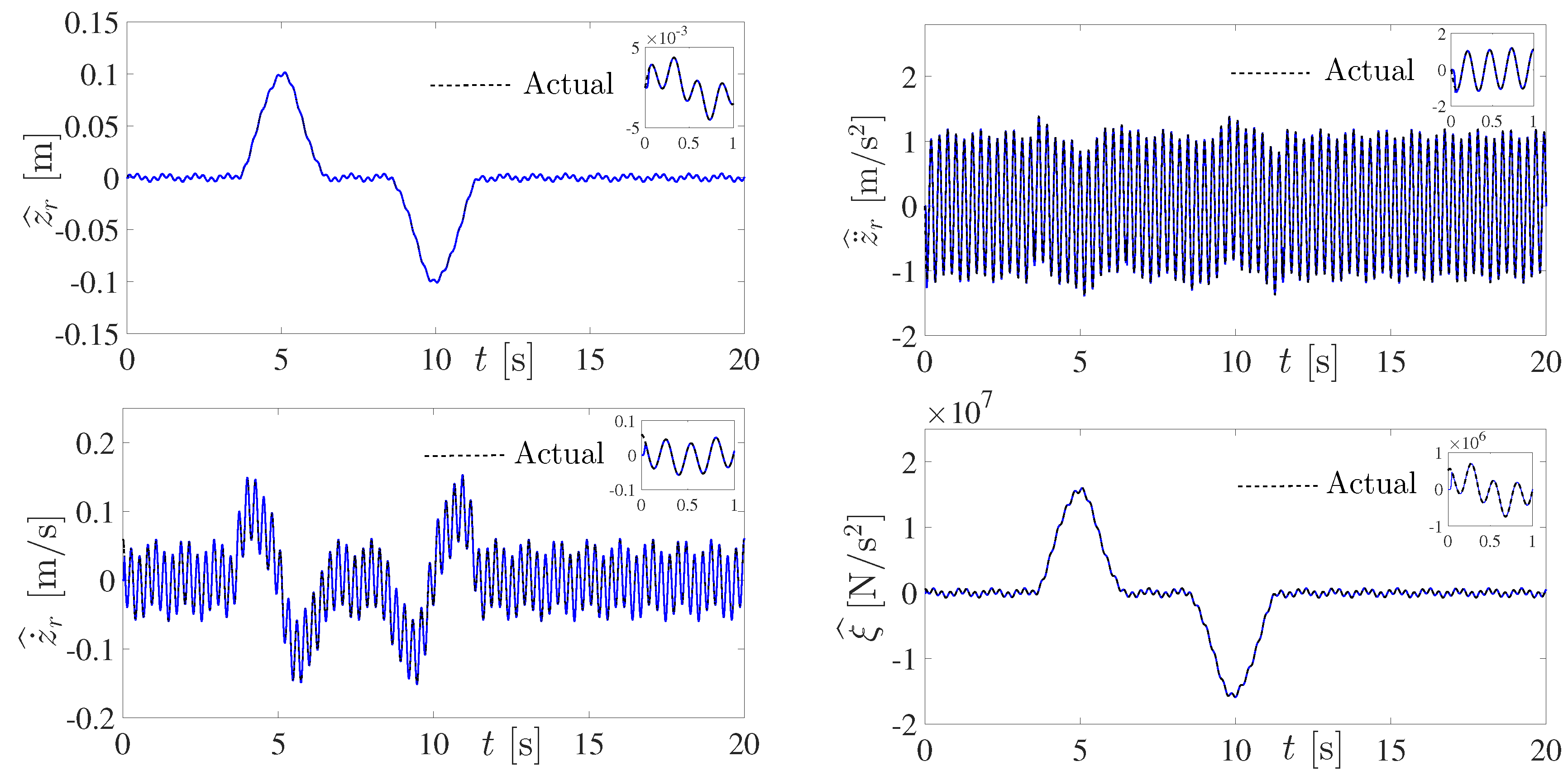
The fast online estimation of the irregular road disturbance trajectories required by the active vibration control is verified in
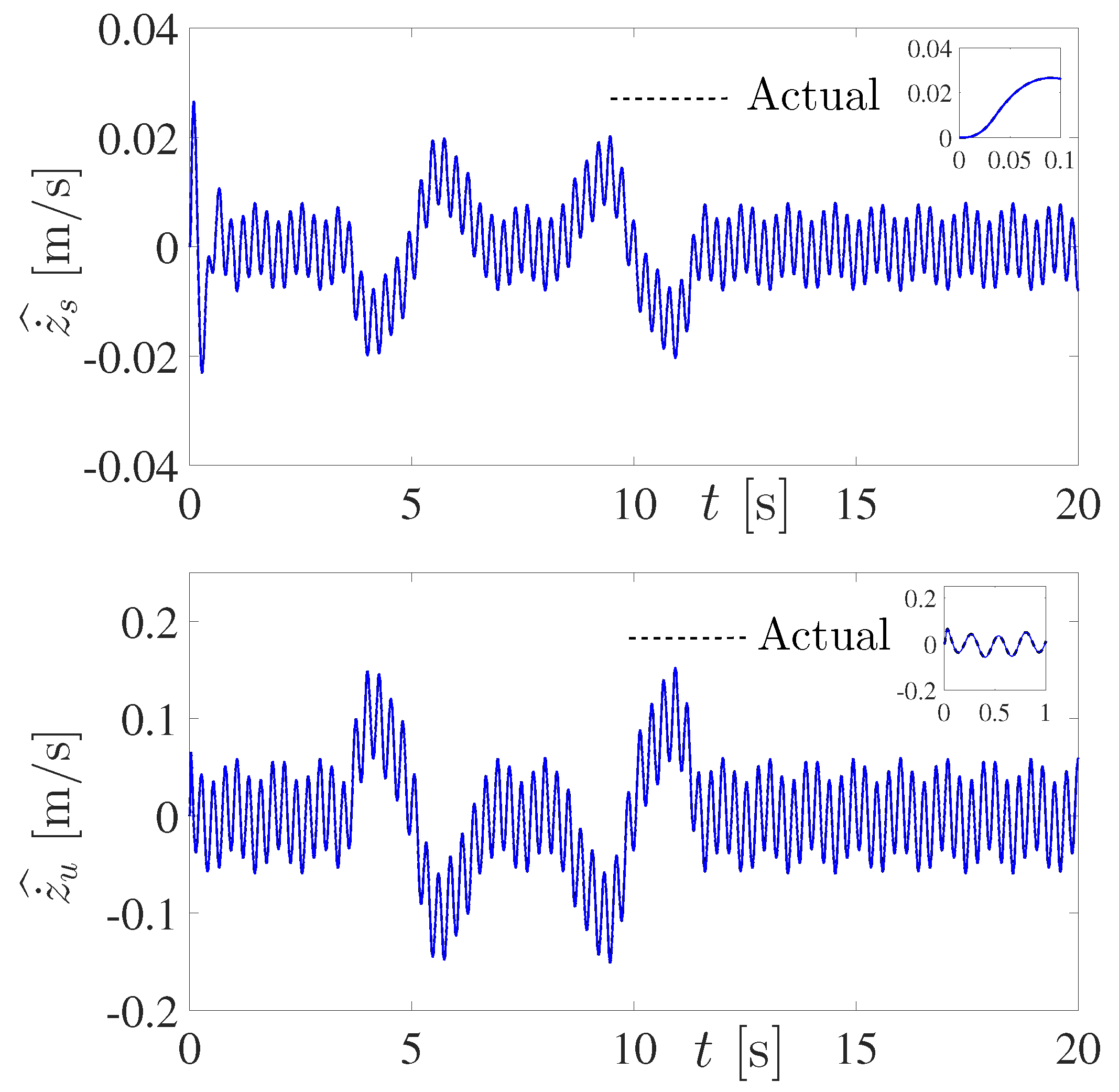
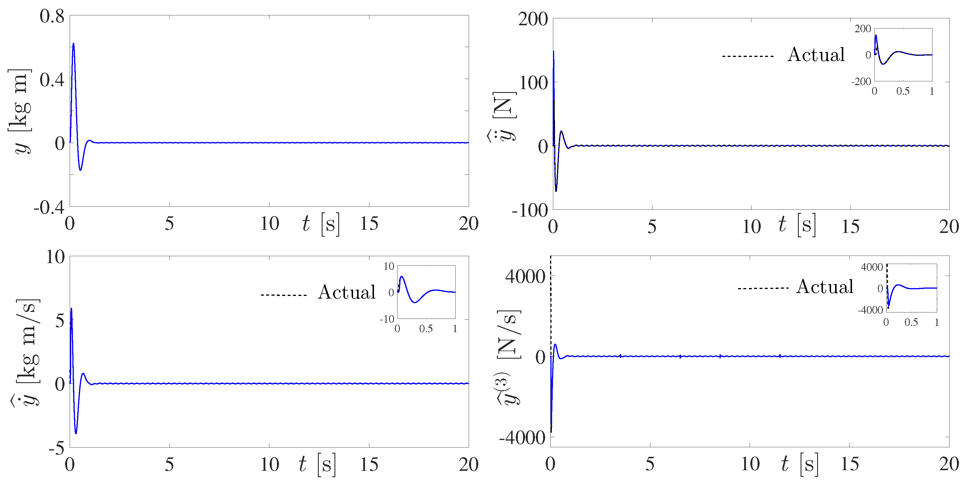
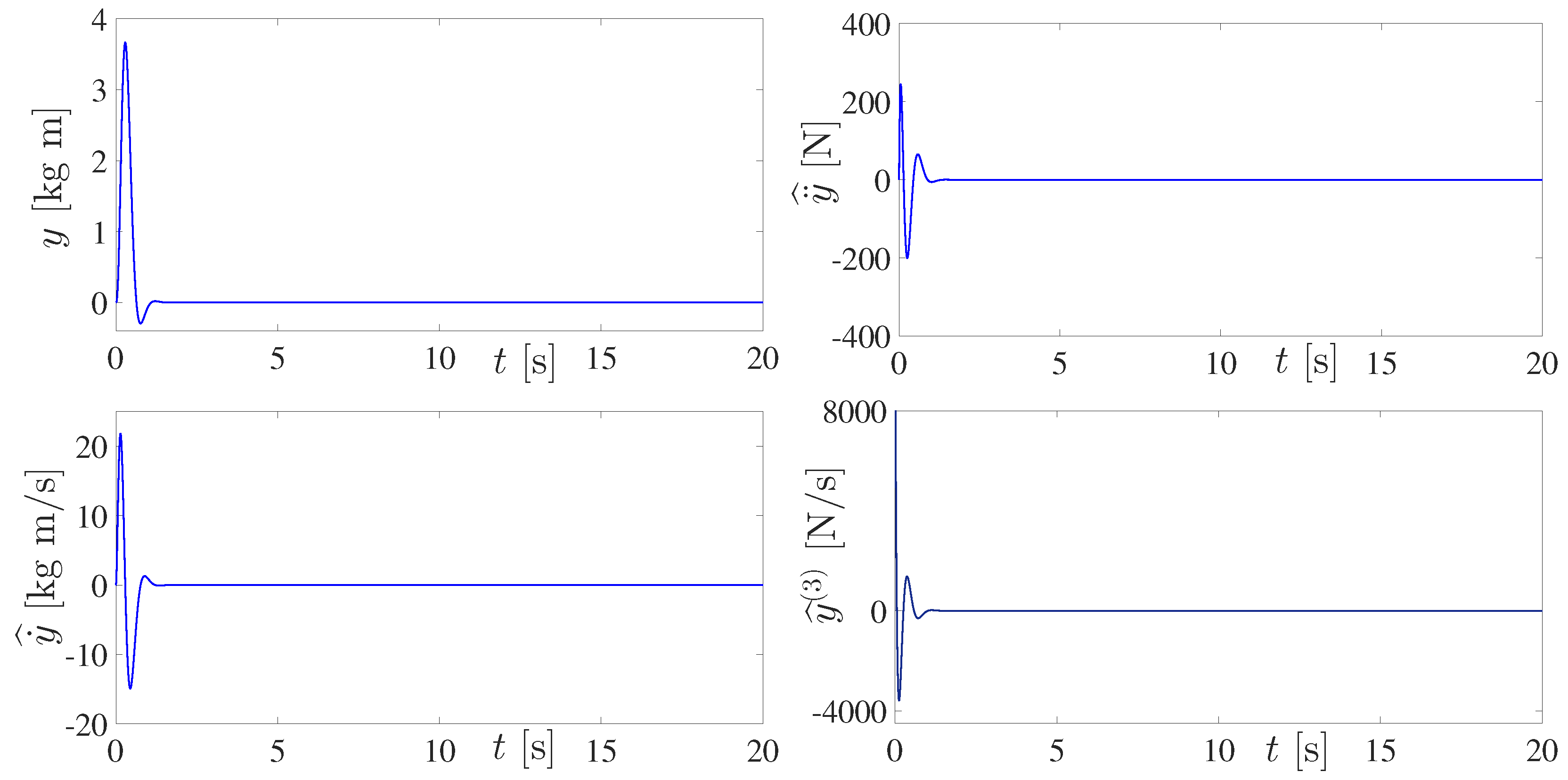
Figure 8. A reasonable active disturbance suppression as well as the satisfactory estimation of the velocity signals and time derivatives of the flat output variable are also evidenced in
Figure 9 and
Figure 10. Estimated signals are gradually injected in the implementation of the proposed active disturbance suppression controller. Thus, the numerical simulation results confirm the effectiveness of the active vibration control scheme based on online disturbance reconstruction, signal differentiation and differentia flatness for vibration attenuation on vehicle suspension systems. For estimation purposes, it has been fixed
in (
24). Indeed the value of
r should be selected according to the particular implementation and signal approximation desired into a small window of time. For instance, a first-order polynomial is commonly used in the classical numerical differentiation method. However, higher-order Taylor polynomial models can obtain a much better approximation of some signal
into a small interval of time. The characteristic polynomial of the high-gain estimation error dynamics was then set as
with
rad/s and
.
Finally, for performance comparison purposes the differential flatness-based controller (
9) was numerically implemented by assuming that time derivatives of the flat output
y and disturbances
are available. Consequently, for this situation the velocity estimator becomes unnecessary. The active cancellation of disturbances affecting the flat output is displayed in
Figure 11. A better forced vibration attenuation level with respect to passive control is shown in
Figure 12. The active control force
u using real-time measurements of position, velocity, acceleration and jerk signals as well as disturbances is depicted in
Figure 13. It can be observed that the overall active suspension system responses are similar to those obtained using the velocity signal estimator. Therefore, it is again confirmed the main advantages of the proposed online estimation perspective to approximately reconstruct velocity and disturbance signals for situations where position measurements are only admissible. Nevertheless, notice that the velocity signal estimation is based on certain order polynomial approximations into a small window of time. Then an approximation of disturbances based on estimated multiple velocity signals is only obtained. Moreover, estimation gains should be suitably chosen in order to quickly compute estimates of signal velocities, faster than undesirable disturbance dynamics. Thus estimates of velocity and disturbance signals have to be smoothly injected into the control action.

 ,
, 


