Experimental Characterization of Bond Fatigue Using Beam-End Tests with Push-In Loading †

Institute of Structural Concrete, RWTH Aachen University, Mies-van-der-Rohe-Straße 1, 52074 Aachen, Germany
*
Author to whom correspondence should be addressed.
†
Presented at the 18th International Conference on Experimental Mechanics, Brussels, Belgium, 1–5 July 2018.
Proceedings 2018, 2(8), 417; https://doi.org/10.3390/ICEM18-05270
Published: 24 May 2018
(This article belongs to the Proceedings of The 18th International Conference on Experimental Mechanics)
Abstract
:Realistic characterization of fatigue loading resistance is a paramount for an economical and reliable structural design of reinforced concrete (RC) and prestressed concrete (PC) structures. The need for innovative experimental methods for the characterization of fatigue behavior is driven by the current aims to construct wind turbine towers that must resist up to N = 107 loading cycles corresponding to 25 years of service life. Considering the number of possible configurations with regard to structural geometries, cross-sectional layout of reinforcement and loading scenarios, experimental data are required that capture the key mechanisms driving the fatigue damage between the reinforcement and concrete matrix. Experimental investigations of bond behavior under fatigue loading have been reported in the literature in the 90′s of last century. Since then, no systematic investigation of bond fatigue behavior has been published. As a consequence, no assessment rules are available for the bond fatigue, only separate assessment rules for concrete and steel. The present paper will report on the ongoing research of bond fatigue behavior using the beam-end test setup. The test campaign includes the push-in loading with the goal to provide data characterizing the compressive behavior of reinforced cross sections in wind turbine towers.
1. Introduction
The advancement of a new energy system against the backdrop of climate change leads inevitably to progress regarding regenerative energies. This energy transition requires the development of more capable wind turbines. More resistant supporting structures such as hybrid constructions consisting of a reinforced (RC) and prestressed (PC) concrete section and a steel section are needed for this reason. Such structures are exposed to up to N = 107 loading cycles over a service life of 20 to 25 years. For the composite materials RC and PC, the bond between concrete and reinforcement is of decisive importance. PC members are over-stressed for some amount of the operating stresses, e.g., the lower section of wind turbine towers. Reinforcement is only arranged to increase the load bearing capacity and robustness. When the wind speed and direction changes, the reinforcement is alternately exposed to compression or tension stresses. Therefore, it must be ensured that the reinforcement fulfills its function and is anchored even under cyclic loading.
The assessment rules regarding the bond behavior between concrete and reinforcement have not been developed for the very-high-cycle fatigue range. Standards and codes are only available separately for the materials concrete and steel. Hence, the design of RC members is restricted for structures exposed to millions of loading cycles. To design economic and efficient structures the demand of a realistic description of the bond behavior under fatigue loading has become more important in the last decades. As a result, the existing assessment rules [1,2] have to be processed on the basis of this research.
The literature delineates a large number of different specimens for bond investigations. Predominantly, bond investigations were carried out under static loads. In 1979 first Rehm & Eligehausen performed pull-out test on cylinder-shaped specimens with a constant bond length exposed to a fatigue loading [3]. Up to N = 106 loading cycles were applied with frequencies up to 0.83 Hz depending on the load level. Balázs conducted pull-out tests on prisms with various bond lengths [4]. In [5] the impact of different amplitudes and loading ranges were investigated.
Investigations regarding the fatigue behavior of RC are very time-consuming considering a test period of up to 24 days (N = 107, f = 5 Hz) and are therefore very costly. For that reason, a combined methodology of experimental and numerical investigations has been adopted.
2. Experimental Investigations
2.1. Beam-End Tests
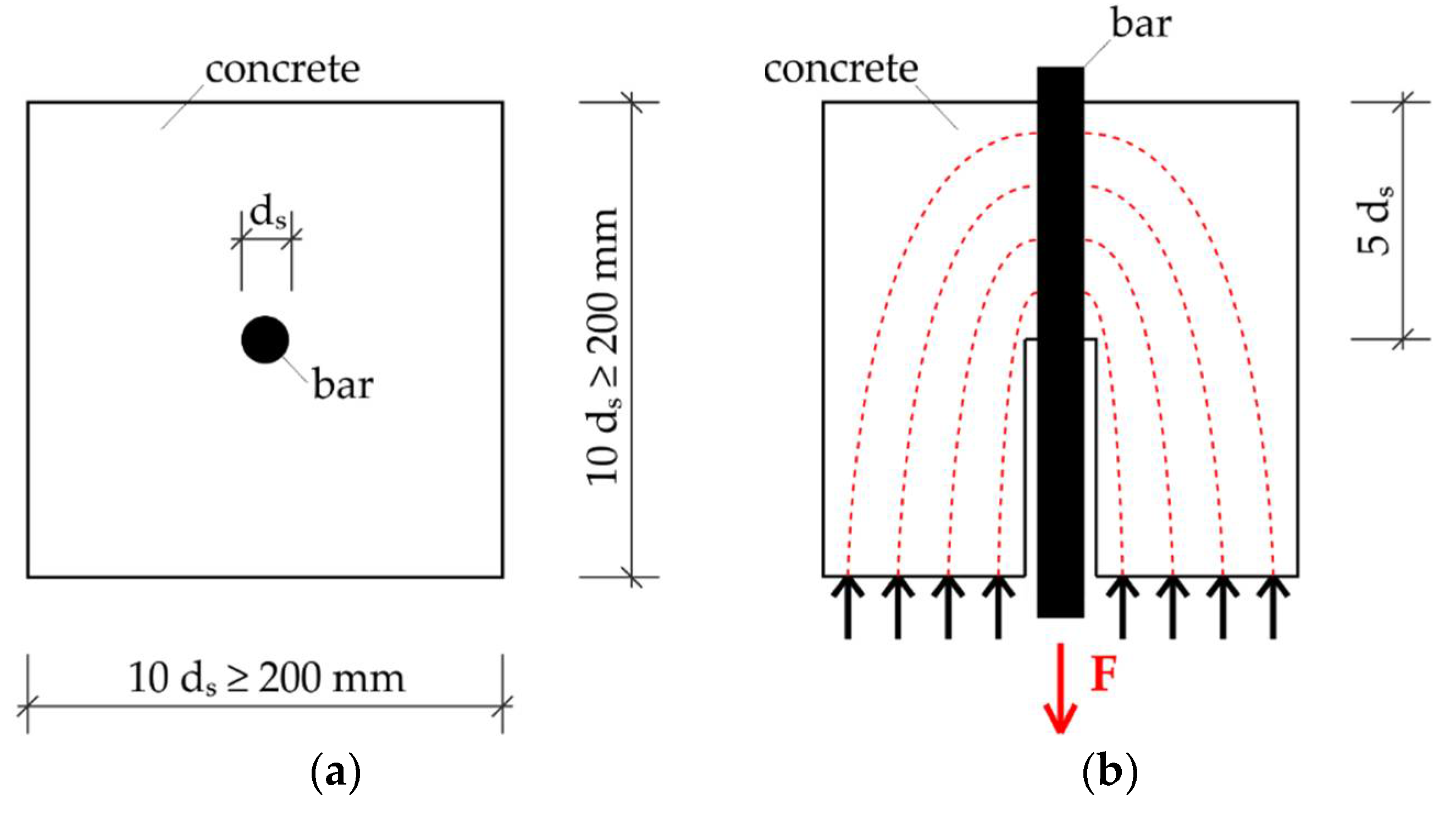
The first standardized test set-up to determine the bond behavior of reinforcing bars in concrete was the Rilem pull-out test [6]. The referenced recommendation describes a cubical concrete specimen with an edge length of 10 ds (at least 200 mm). Also the bond length depends on the bar diameter and is set to 5 ds. The steel bar is arranged in the center of the cube (Figure 1). Although these are relatively simple specimens, beam-end tests were performed. For the presented investigations the Rilem pull-out test is not suitable, since on the one hand the splitting cracks can only be insufficiently investigated due to the large concrete cover and on the other hand the bond stresses are significantly influenced by the transverse pressure [7].
For the reasons mentioned above, the experiments presented in this paper were conducted with modified beam-end specimens in reference to [8]. In addition, the concrete cover and the bond length as well as optional stirrup within the bond length are freely selectable [9]. So, it is also possible to evaluate the splitting cracks proceeded from ribbed bars.
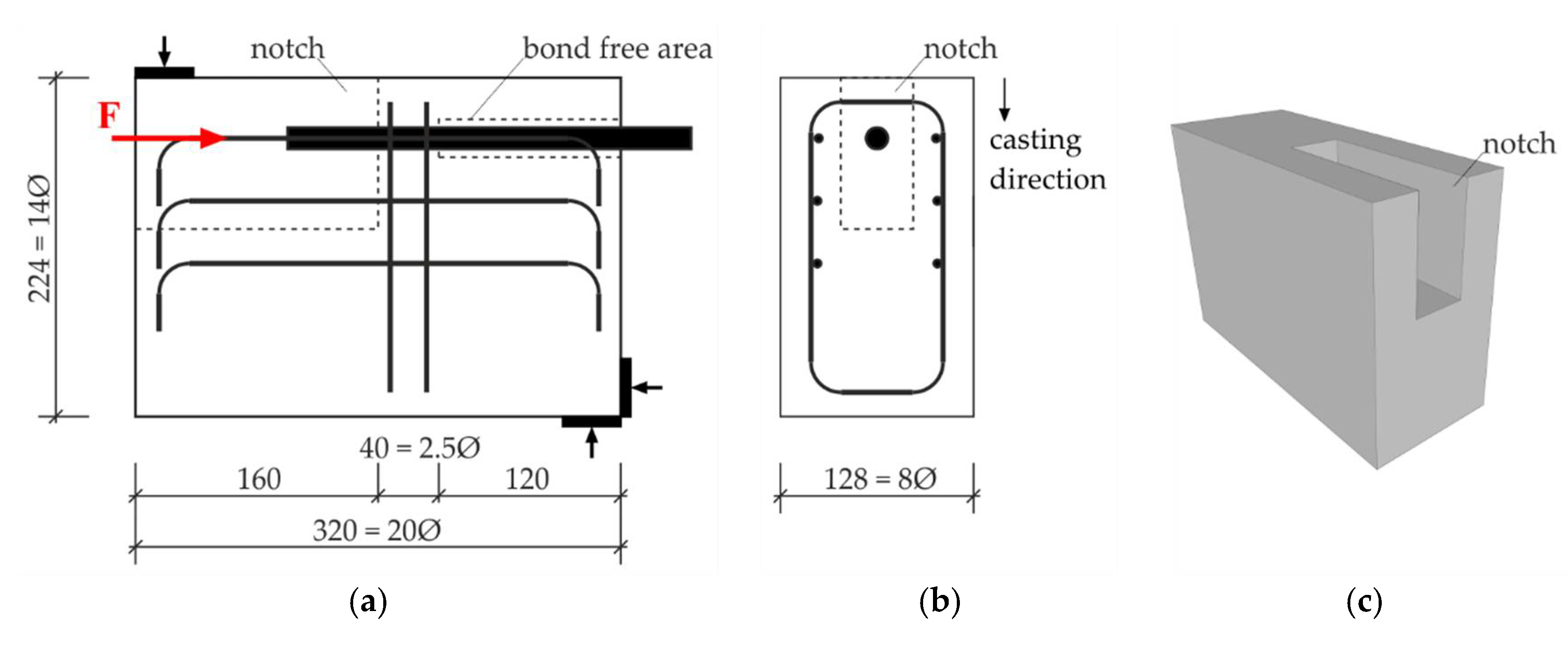
According to [9], the dimensions have been adjusted with the result that all dimensions are related to the bar diameter. Against the background of experiments with other diameters the relationship between length, width, height, bond length and concrete cover remains constant and comparable as well. The dimensions were set to L × W × H = 20 ds × 8 ds × 14 ds (Figure 2a). The diameter was ds = 16 mm. To characterise the bond behavior in a realistic mode the concrete cover was set to 2 ds. The bond length was 2.5 ds in all experiments to ensure the disposal of three ribs at minimum within and is followed by a bond free area of 7.5 ds. Within the bond length two stirrups were arranged to retain the splitting cracks width small. To prevent failure of the concrete cross-section in the field of the notch due to the cyclic loading three layers of longitudinal reinforcement bars were deposited (Figure 2a). The largest adjustment regarding the test set-up was made in the type of the loading direction. Both, the Rilem test and the Astm test provide a pull-out force. As mentioned above, RC structures can be exposed alternating to compressive or tension stresses, e.g., wind turbine towers. Therefore, the investigations were performed with a push-in load applied to the reinforcing bar. To avoid buckling of the steel bar resulting from the compressive load a notch in the concrete body had to be provided.
2.2. Material Properties
The concrete used for the beam-end tests can be classified in concrete strength class C100/115 [10]. Up to six beam-end specimens were casted within one batch to ensure the same concrete properties. For quality assurance and to ensure the comparability of the individual casting batches material tests were conducted concomitantly. The compressive strength of the concrete as well as the Young’s Modulus were determined with cylinders with a diameter of 150 mm and a height of 300 mm and cubes with an edge length of 150 mm [11]. Respectively, three cubes and three cylinders were performed as material tests at the same day of the beam-end tests. The compressive strength was fcm,cube = 120 MPa for the cubes, fcm,cyl = 108 MPa for the cylinders and the Young’s Modulus was Ecm = 49,900 MPa after 28 days. For clarification, the cubes and cylinders were stored at the laboratory similar to the investigated specimen.
The used reinforcement bars with a diameter of 16 mm were hot-rolled and heat treated and can be classified as B500B [12]. The bars have two longitudinal ribs and two rows of inclined ribs. The ribs of one row alternately have different inclinations.
2.3. Loading Scenarios and Test Set-Up
The test load, the machine stroke and the crack width at the concrete surface were measured continuously using linear variable differential transformers (LVDTs). Respectively, one LVDTs were mounted the loaded and the unloaded end to record the slip of the bar. Additionally, two LVDTs were assembled in the field of the bond zone to measure the widths of splitting cracks and cracks perpendicular to the bar.
To characterize the bond fatigue behavior, a test campaign has been planned which contains several different loading scenarios. Ensuing from monotonic loading, cyclic tests with a maximum of 1000 loading cycles through to fatigue tests with N = 107 loading cycles several configurations also with changing amplitudes will be conducted. In the present paper, first, results obtained from the monotonic and a cyclic loading scenario are presented.
In the course of the monotonic loading scenario LS-1, the bar has been loaded displacement controlled with 1.0 mm/min until the slip at the unloaded end was about 8 mm. Hereby, the ultimate push-in load of a specimen was quantified. For the cyclic loading scenario, the lower and upper load levels were determined in dependence to the average maximum load. The cyclic loading scenario LS-2 is defined by a constant lower load level and a step-wise increasing upper loading level. At each upper loading level ten cycles are performed before the incremental increase of ΔS = 0.05. Table 1 depicts the related loads as well as the number of cycles.
Unlike the monotonic LS-1, the experiments with the cyclic LS-2 were loaded force controlled with a frequency of 0.02 Hz. At the beginning of the beam-end tests, the lower loading level was approached before the sinusoidal compressive threshold loading was applied.
3. Numerical Modelling of Beam-End Tests
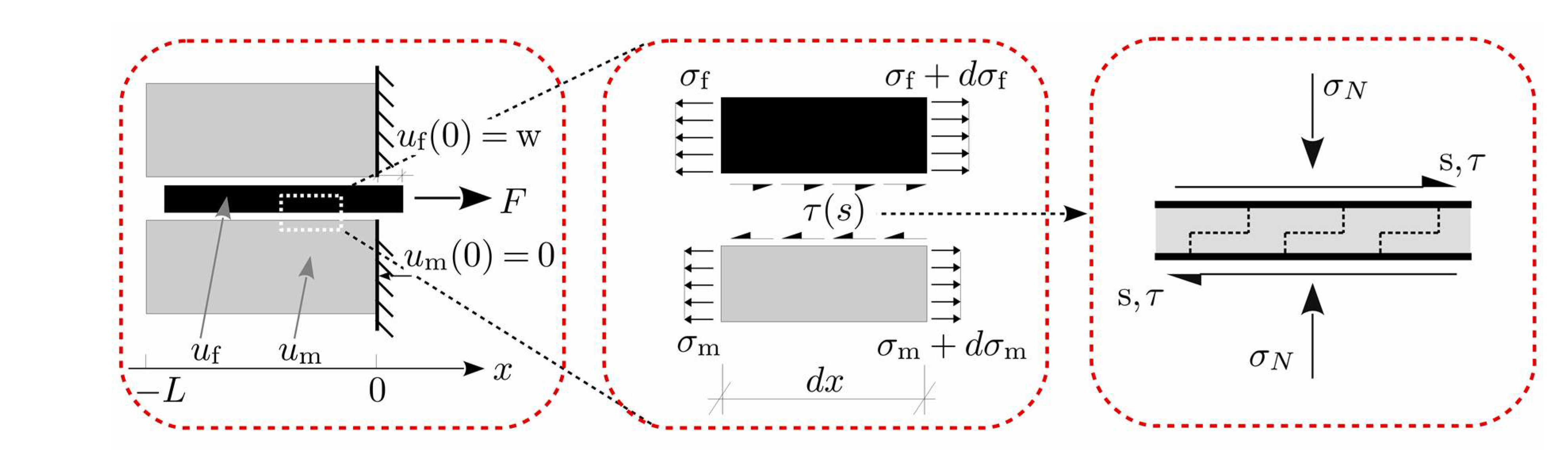
The conducted beam-end tests can be simulated using a bond fatigue model developed recently by the authors [13,14]. The model is based on a coupled damage and inelastic sliding within the bond interface with sensitivity to the lateral pressure/tension. The fatigue damage is based on a cumulative measure of the inelastic slip. The proposed material model has been implemented into the standard finite element framework as an implicit time-stepping algorithm incrementally integrating the evolution equations. This is embedded into the initial boundary value problem representing the pull-out test setup (Figure 3).
4. Results and Discussion
First three beam-end tests with monotonic loading (LS-1) have been investigated to determine the lower and upper loading levels of the cyclic loading scenario (LS-2). The average maximum load of these tests was Fmax,m = 75 kN. The corresponding compressive deformation at the unloaded end was δm = 0.16 mm. For LS-2 the lower loading level was set to Flo = 7.5 kN while the upper loading level was between Fup,1 = 37.5 kN and Fup,10 = 71.3 kN (cf. Section 2.3).
Figure 4a shows the results of three beam-end tests under monotonic loading. In this diagram the load is plotted against the displacement at the unloaded end. It can be observed that the influence of the positioning of the ribs can be neglected, since on the one hand comparable maximum loads and on the other similar softening branches have been achieved.
In Figure 4b the applied load is plotted against the displacement at the unloaded end for the cyclic loading scenario. It is observable that the relation between the force and the slip confirms to the constant lower load and the stepwise increasing of the upper load. This specimen failed after 100 cycles at about 71 kN with an end-slip of about 0.3 mm.
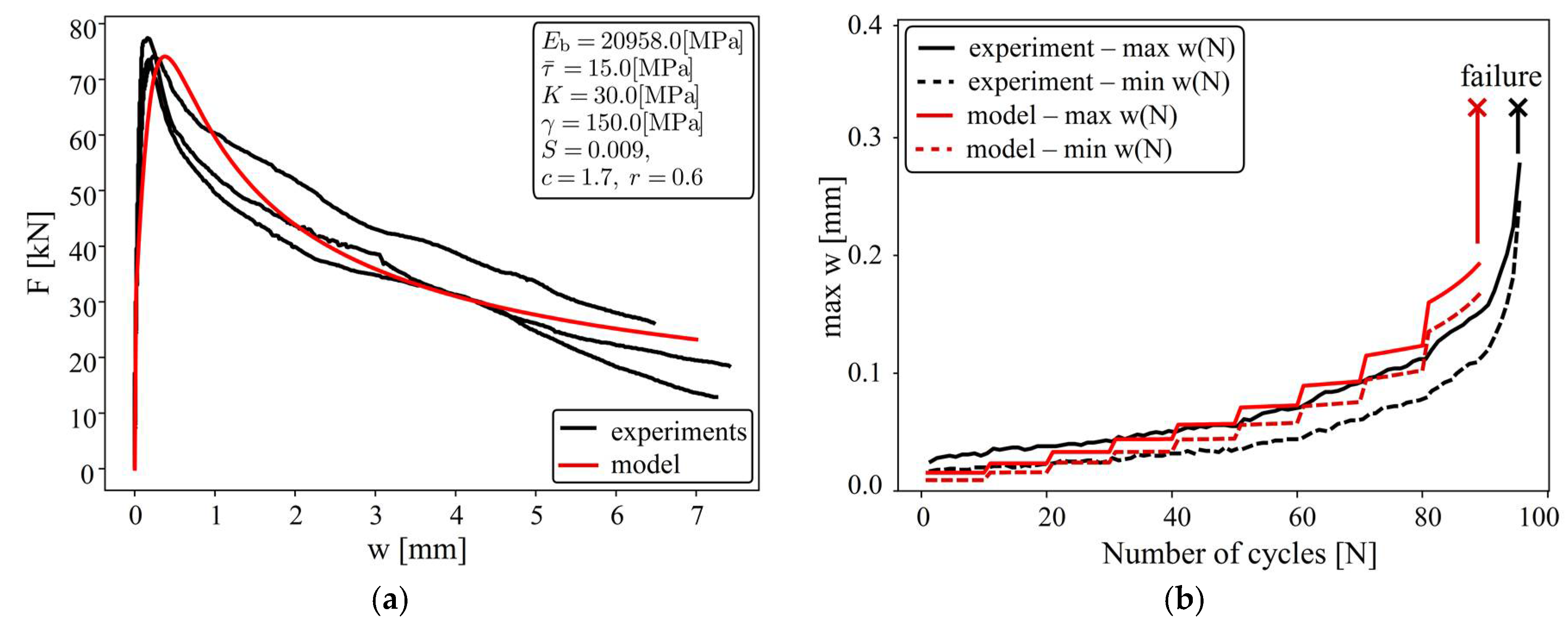
The evolution of the displacement at the lower and upper loading levels is plotted in Figure 6b. The black curves represent the experimental results. During the first 15 to 20 loading cycles the displacement at the lower loading level remained almost constant and increases afterwards while the displacement at the upper loading level increases from the beginning of the test.
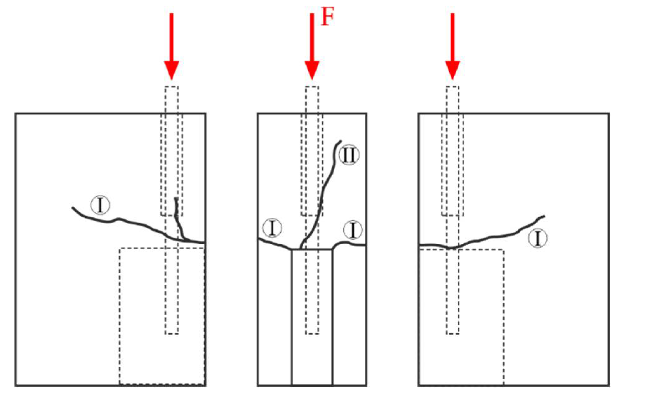
In the course of the beam-end tests perpendicular cracks occurred at the corners of the indented zone (Figure 5, crack I). Due to the longitudinal reinforcement, the crack width was limited to 0.1 mm. As depicted in Figure 5 at least one longitudinal crack propagated along the embedded length (crack II). These cracks started to evolve from the loaded end of the push-in bar. The longitudinal cracks were confined by the stirrups with a width up to 0.3 mm. A similar crack-pattern has been observed for both loading scenarios LS-1 and LS-2.
The conducted beam-end tests have been also simulated using the bond fatigue model described in Section 3. The model parameters for the combination of steel reinforcement and concrete matrix have been identified from the monotonic and cyclic response and are summarized in Figure 6a.
The monotonic pull-out curve for the test and the obtained numerical curve are shown in Figure 6a. The fatigue creep curves under the cyclic loading scenario for the upper and the lower loading levels are depicted in Figure 6b.
5. Conclusions and Forecast
The combined experimental and numerical investigations of the bond fatigue behavior provide a good basis for a realistic characterization of the bond fatigue behavior in a wide range of loading scenarios. In the present form, the numerical model cannot reflect all the aspects of the bond fatigue behavior. As discussed previously, the longitudinal cracks develop along the embedded bar and affect the bond level. The presented version of the model describes this behavior as unidimensional debonding between the concrete and reinforcement. In spite of that, the obtained numerical results look promising and provide the framework for further detailing.
The model shows the ability to reproduce both the monotonic and cyclic behavior of the bond with a single set of material parameters. Further improvements of the model will be done in the future to include the effect of the splitting cracks occurring in beam-end test.
Further investigations will be required to obtain a comprehensive characterization of the bond behaviour under fatigue loading. A paramount aspect of these investigations is to calibrate and validate the numerical model, so the experiments can be reduced to a minimum. In order to achieve the purpose of a realistic numerical computation of the fatigue bond behaviour, tests will be conducted with additional loading scenarios in the future. Also the influence of a larger diameter of the reinforcement will be investigated. Finally, beam-end tests with end bearing will be conducted to investigate the fatigue behavior of reinforcement splices.
Acknowledgments
This research project is part of the collaborative research project WinConFat (0324016C2) founded by the Federal Ministry for Economic Affairs and Energy (BMWi). The authors acknowledge the support gratefully.
References
- Deutsches Institut für Normung e. V. Eurocode 2: Bemessung und Konstruktion von Stahlbeton-und Spannbetontragwerken-Teil 2: Betonbrücken-Bemessungs-und Konstruktionsregeln; Beuth Verlag: Berlin, Germany, 2010. [Google Scholar]
- Deutsches Institut für Bautechnik. Richtlinie für Windenergieanlagen-Einwirkungen und Standsicherheitsnachweise für Turm und Gründung; Schristen des Deutschen Instituts für Bautechnik B: Berlin, Germany, 2012; No. 8. [Google Scholar]
- Rehm, G.; Eligehausen, R. Bond of Ribbed Bars Under High Cycle Repeated Loads. ACI J. Proc. 1979, 76, 297–310. [Google Scholar] [CrossRef]
- Balázs, G.L. Fatigue of Bond. ACI Mater. J. 1992, 88, 620–629. [Google Scholar] [CrossRef]
- Balázs, G.L. Bond under Repeated Loading. ACI Spec. Publ. 1998, 180, 125–143. [Google Scholar] [CrossRef]
- International Union of Testing and Research Laboratories for Materials and Structures. RILEM Technical Recommendations for the Testing and Use of Construction Materials; E & FN Spon: London, UK, 1994. [Google Scholar]
- Schoening, J.; Hegger, J. Überprüfung der zusätzlichen Regeln für ∅︁40 mm nach EC2. Beton-und Stahlbetonbau 2015, 110, 578–587. [Google Scholar] [CrossRef]
- proceedings-02-00417. Standard Test Method for Comparing Bond Strength of Steel Reinforcing Bars to Concrete Using Beam-End Specimens (A944-10); ASTM International: West Conshohocken, PA, USA, 2015. [Google Scholar]
- Schoening, J.; Hegger, J. Investigation of Reinforcement Anchorages with Large Diameter Bars. In High Tech Concrete: Where Technology and Engineering Meet. Proceedings of the 2017 fib Symposium; Hordijk, D.A., Luković, M., Eds.; Hordijk, D.A., Luković, M., Eds.; Springer: Cham, Switzerland, 2018. [Google Scholar]
- Deutsches Institut für Normung e. V. Eurocode 2: Bemessung und Konstruktion von Stahlbeton-und Spannbetontragwerken-Teil 1-1: Allgemeine Bemessungsregeln und Regeln für den Hochbau (DIN EN 1992-1-1); Beuth Verlag: Berlin, Germany, 2011. [Google Scholar]
- Deutsches Institut für Normung e. V. Prüfung von Festbeton–Teil 2: Herstellung und Lagerung von Probekörpern für Festigkeitsprüfungen (DIN EN 12390-2); Beuth Verlag: Berlin, Germany, 2009. [Google Scholar]
- Deutsches Institut für Normung e. V. Betonstahl-Betonstabstahl (DIN 488-2); Beuth Verlag: Berlin, Germany, 2009. [Google Scholar]
- Baktheer, A.; Chudoba, R. Pressure-sensitive bond fatigue model with damage evolution driven by cumulative slip: Thermodynamic formulation and applications to steel- and FRP-concrete bond. Int. J. Fatigue 2018, 113, 277–289. [Google Scholar] [CrossRef]
- Baktheer, A.; Chudoba, R. Modeling of bond fatigue in reinforced concrete based on cumulative measure of slip. In Proceedings of the the Computational Modelling of Concrete Structures, EURO-C 2018, Bad Hofgastein, Austria; CRC Press: Bad Hofgastein, Austria, 2018; pp. 767–776. [Google Scholar]
Figure 1.
Rilem pull-out test set-up: (a) top view of the specimen; (b) cross-section with lateral stresses.
Figure 1.
Rilem pull-out test set-up: (a) top view of the specimen; (b) cross-section with lateral stresses.

Figure 2.
Modified beam-end test specimen: (a) longitudinal cross-section; (b) cross-section; (c) 3D-view.
Figure 2.
Modified beam-end test specimen: (a) longitudinal cross-section; (b) cross-section; (c) 3D-view.

Figure 3.
Mechanical model for the pullout initial boundary value problem.

Figure 4.
Experimental results: (a) load-displacement behavior under monotonic loading; (b) load-displacement behavior under cyclic loading.
Figure 4.
Experimental results: (a) load-displacement behavior under monotonic loading; (b) load-displacement behavior under cyclic loading.

Figure 5.
Crack pattern after tests with loading scenario LS-1.

Figure 6.
Simulation of beam-end test: (a) displacement versus pullout force under monotonic loading; (b) fatigue creep curves for the loading level (LS2) at the upper and lower loading.
Figure 6.
Simulation of beam-end test: (a) displacement versus pullout force under monotonic loading; (b) fatigue creep curves for the loading level (LS2) at the upper and lower loading.


Table 1.
Table 1. Loading scenarios for the presented beam-end tests.
| Loading Scenario | Related Loads | Number of Cycles | Figure |
|---|---|---|---|
| LS-1 | monotonic | (N = 1) |  |
| LS-2 | Smin = 0.1 Smax = 0.5 − 0.95 Smid = 0.3 − 0.525 | N = 100 |  |
Publisher’s Note: MDPI stays neutral with regard to jurisdictional claims in published maps and institutional affiliations. |
© 2018 by the authors. Licensee MDPI, Basel, Switzerland. This article is an open access article distributed under the terms and conditions of the Creative Commons Attribution (CC BY) license (https://creativecommons.org/licenses/by/4.0/).
Share and Cite
MDPI and ACS Style
Camps, B.; Baktheer, A.; Hegger, J.; Chudoba, R. Experimental Characterization of Bond Fatigue Using Beam-End Tests with Push-In Loading. Proceedings 2018, 2, 417. https://doi.org/10.3390/ICEM18-05270
AMA Style
Camps B, Baktheer A, Hegger J, Chudoba R. Experimental Characterization of Bond Fatigue Using Beam-End Tests with Push-In Loading. Proceedings. 2018; 2(8):417. https://doi.org/10.3390/ICEM18-05270
Chicago/Turabian StyleCamps, Benjamin, Abedulgader Baktheer, Josef Hegger, and Rostislav Chudoba. 2018. "Experimental Characterization of Bond Fatigue Using Beam-End Tests with Push-In Loading" Proceedings 2, no. 8: 417. https://doi.org/10.3390/ICEM18-05270