A Mirror-Based Active Vision System for Underwater Robots: From the Design to Active Object Tracking Application
 Noel Cortés-Pérez
 Luz Abril Torres-Méndez
- CINVESTAV Unidad Saltillo. Robotics and Advanced Manufacturing Group, Ramos Arizpe, Mexico
A mirror-based active system capable of changing the view’s direction of a pre-existing fixed camera is presented. The aim of this research work is to extend the perceptual tracking capabilities of an underwater robot without altering its structure. The ability to control the view’s direction allows the robot to explore its entire surroundings without any actual displacement, which can be useful for more effective motion planning and for different navigation strategies, such as object tracking and/or obstacle evasion, which are of great importance for natural preservation in environments as complex and fragile as coral reefs. Active vision systems based on mirrors had been used mainly in terrestrial platforms to capture the motion of fast projectiles using high-speed cameras of considerable size and weight, but they had not been used on underwater platforms. In this sense, our approach incorporates a lightweight design adapted to an underwater robot using affordable and easy-access technology (i.e., 3D printing). Our active system consists of two arranged mirrors, one of which remains static in front of the robot’s camera, while the orientation of the second mirror is controlled by two servomotors. Object tracking is performed by using only the pixels contained on the homography of a defined area in the active mirror. HSV color space is used to reduce lighting change effects. Since color and geometry information of the tracking object are previously known, a window filter is applied over the H-channel for color blobs detection, then, noise is filtered and the object’s centroid is estimated. If the object is lost, a Kalman filter is applied to predict its position. Finally, with this information, an image PD controller computes the servomotor articular values. We have carried out experiments in real environments, testing our active vision system in an object-tracking application where an artificial object is manually displaced on the periphery of the robot and the mirror system is automatically reconfigured to keep such object focused by the camera, having satisfactory results in real time for detecting objects of low complexity and in poor lighting conditions.
1 Introduction
Given the recent technological progress in the design of unmanned underwater vehicles, either remotely operated (ROVs) or autonomous (AUVs), these devices have become available to many researchers in different areas of study. In order to improve navigation of these vehicles, several methods and technologies have been used to obtain information about the marine environment, such as laser and sonar systems. Nonetheless, these technologies are in general considered invasive since both artificial-generated lightwaves and soundwaves disrupt the natural environment of marine life.
For the development of submarine vehicles or robots, vision-based systems are typically included within the set of sensors of such platforms as the main means of perception, this is due to the benefits they offer, such as the acquisition of high-resolution images, non-invasiveness and low cost.
However, in order to perform a complete autonomous navigation using only visual information, underwater vehicles need accurate and reliable information (Zelinsky, 1992; Choset et al., 2005). That is to say, the captured images must show as clear as possible, all the features of the surrounding objects in any navigation path. Thus, the obtained features must be enough to classify what is perceived in the scene, in order to detect regions of interest to be followed and obstacles to be avoided (Manley, 2003). Both cases involve computing a set of feasible trajectories in real time in order to get an autonomous-effective navigation.
Some of the challenges of underwater vision systems are strictly related with inherent conditions to submarine environments, e.g., sea snow, existence of pollutants, type of local flora and fauna, changes in climate (Erdogan and Yilmaz, 2014); others are related with photometric aspects (Li et al., 1997), (e.g., changes in coloration (Yamashita et al., 2007) due to the source of illumination, and eventually, those that are caused by changes in the light propagation medium. All these conditions are inevitable, and although the progress of underwater camera’s sensors technology together with the knowledge on the capturing process of objects in motion Silvatti et al. (2013) can help to reduce some of their effects, adding complexity to the system will always have an impact in the cost of developing any underwater robotic platform. In recent years, the problem of detection and tracking of underwater moving objects has received considerable attention Zuzi et al. (2018); Panda and Nanda (2020) due to wide applications in oceanographic research. It is clear thus, the need of an autonomous navigation system capable of detecting and tracking underwater moving objects of interest.
At this point, it is important to highlight two additional critical factors for underwater navigation: narrow field of vision (FOV) and image distortion. The reduction of the FOV is a crucial factor that impacts the performance of any visual navigation strategy, because a small FOV ties down information of surrounding obstacles and, therefore, limits the response capacity in maneuvers to avoid collisions. One could think that a practical solution to this problem would be to add several cameras oriented at different angles. However, distortion will persist in each camera, and what is worse, the computational cost for image analysis would increase linearly in proportion to the number of cameras.
One of the alternatives used to obtain information from the periphery, although not in a permanent way, is the use of a servo-actuated camera capable of actively varying its orientation. The use of this strategy in underwater robots also requires work for conditioning the entire device to be waterproof and to support the environment high pressures. Adding this robust system to a commercial robot entails the loss of the hydrodynamic profile of the AUV, and specially causing undesirable dynamic effects, especially for the displacement, due to the action and movement of the camera’s components and, in general, a modification of the entire design of the AUV.
Another alternative that has gained popularity among the research community in terrestrial and erial robots is the use of fisheye cameras, which offer a wide FOV, with viewing angles up to 180° (Ishibashi, 2010). However, one disadvantage that this type of lenses presents is the spatial image distortion, having more density information at the edges of the image, in other words, the information that is concentrated in the center of the image has high resolution and at the edges has very poor resolution (in terms of space pixel density). Additionally, most of these camera lenses have been designed for ground applications, where air is the interface for light diffusion. Therefore, in underwater applications (a different environment for which they were designed), the fish-eye lenses advantages are reduced (Agrawal et al., 2012).
There are research works in terrestrial environments (Okumura et al., 2011; Lee et al., 2012; Okumura et al., 2013; Lelais et al., 2019), where an active mirror system is capable of tracking high-speed particles (like a bullet) (Lee et al., 2012) using a robust and heavy recording hardware. Based on this strategy, the proposed solution has a novel mountable device based on mirror optics, which through the automatic movement of flat mirrors (Agrawal et al., 2012) can change the main angle of the preexisting fixed camera and obtain information from the periphery of the AUV.
The main contribution of this research work is to enable existing robotic platforms, which vision systems can no longer be modified, with a wider viewing angle. The proposed solution is to use active mirrors to change the angle of vision of a fixed camera system. The weight and size of an active mirror system are usually much smaller than the mechanisms used to move a complete vision system. Additional benefit is the use of existing hardware without having to invest in completely changing the design of the platform, which in most cases is impossible to perform.
Designed for ocean exploration applications, the proposed active mirror system has been experimentally tested to visually track a moving target in a coral reef environment. Based on the shape and color of the object of interest and using projective geometry, it is possible to estimate the spatial location of the object with respect to the robot’s referential frame. The visual tracking is performed using a PID control strategy to generate the motion directives of the active mirror system, having as an input reference the position of the centroid of the object in the image plane, its speed and the estimated position by using a Kalman’s filter.
To deal with the variations in color in underwater environments, we use the HSV-space color space which has been successfully reported for real-time applications due to its low computational cost. To deal with possible sunlight reflections, the system’s own design conceals the mirror system of direct Sun exposure with the robot’s own body. For the analysis of active mirror visual information, a bi-cubic interpolation method is used to compute the projection of points that belong to mirror area, then a homography is computed to extract an image blob of the reflective surface.
The outline of the paper is as follows. Section 2 presents detailed information about prototype design, the kinematics of the mirror movement as well as a virtual camera model. The process of image analysis (segmentation and extraction of the mirror projection region) is contained in Section 3, as well as the method used for object tracking using a segmentation process in the HSV color space. The control algorithm of the mirror system is presented in Section 3.5, where all the blobs are geometrically weighted to estimate the centroid of the object, then a Kalman Filter is performed to predict the object velocity in image in order to implement PID control. The experimental results and analysis of the performance are presented in Section 4. Finally, the conclusions and future work are given in Section 5.
2 Mirror System Configuration and Design
Several research work on robot navigation and exploration have successfully tested active-camera vision systems (Manley, 2003; Yahya and Arshad, 2016; Vidal et al., 2018). Despite the diversity of approaches in these works, the pan-tilt movement scheme has been widely chosen because of its simplicity. Our work continues on this trend but instead of using a mechanism to directly generate directly pan-tilt motion in the camera, we use mirrors.
The idea of using mirrors in the design of our active system is inspired by the mechanism of the single-lens reflex camera (SLR). In this type of camera, a moveable mirror behind the lens reflects an image through a pair of mirrors, onto the viewfinder. Thus, in an inverse approach, one could think of changing the direction of light beams from around the robot and focus them to the camera sensor with the appropriate motion of the mirror. Taking this approach as a reference, it has to be considered the reflection of the principal axis of view and that the mirrors must be on the camera’s FOV.
In this section, the details on the design and the kinematics of the mirror system is described. First, we address a fundamental aspect in the design of any mirror system: the distance between the mirror and the camera. On one hand, if the mirror is placed very close to the camera, the virtual image on the mirror could present occlusions caused by the reflection of the body of the robot, thus dramatically reducing the useful field of view of the device (see Figures 1A,B). On the other hand, if the mirror is placed too far from the camera (Figure 1C), it would require a very large mirror in order to use the majority of the image area due to the perspective. In addition, for applications involving underwater or even erial vehicles, if we opt for a long support with a mass at the end (mirror), it could change dramatically the center of mass of the system which in turn will change the dynamic parameters needed for dynamic-based controllers. In Okumura et al. (2011), the authors try to solve this problem by using a set of lenses called “pupil transfer lenses” as an alternative to reduce mirror size. However, for the proposed development, this is not a feasible solution for underwater environments, due to variations in light propagation.
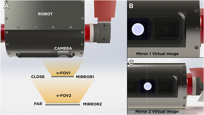
FIGURE 1. Illustrative comparison of virtual images produced by the mirror position. (A) General Overview of two scenarios. (B) Virtual Image produced when mirror is placed near from the robot’s camera. (C) Virtual Image produced when mirror is placed near from the robot’s camera.
To address possible robot-body occlusion a system composed by two mirrors
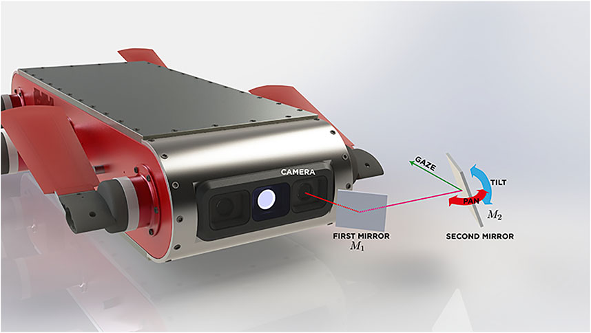
FIGURE 2. A two-mirror system design interacting with the AUV’s camera.
2.1 Virtual Camera Kinematics
One of the disadvantages of including a system of two mirrors in relation to the system of a single mirror is that the mathematical model of motion of the virtual camera grows in complexity. However, with some design considerations, it is possible to simplify the motion model of the system.
The first aspect that can been taken into account to simplify the kinematic model is to consider a constant translation between the reference frames of each of the mirrors, then the pose of the first mirror
A simple scheme of this mirror-camera arrangement is represented in Figure 3. It is assumed that reference frame
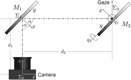
FIGURE 3. Reference frames of the system. Since we assume a system of fixed cameras on the robot, we consider a frame
First transformation (rotation and displacement
where
As mentioned above, we consider the origin of the reference
So far, we have only discussed about the description of the movement of the center of the mirror with respect to the center of the camera as a function of the joint coordinates
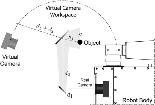
FIGURE 4. Virtual camera workspace. Since
As it can be seen, the mapping of the camera’s motion is nonlinear, thereby it is difficult to model an inverse relationship (i.e., there is not a unique inverse mapping) that allows us to choose a joint configuration given a desired position of the virtual camera. However, the true objective and challenge in most of the active vision systems, is to find the necessary variations for a system reconfiguration.
Different numerical and artificial intelligence methods have been tested in order to solve this inverse mapping, restricted to joint boundary and initial conditions. In this research work, we focus on the development of the active vision system, its kinematics model and its use in a real environment applications. However, at this point, with a general model it is not possible to describe completely motion constraints as well as the practical functional limits (considering mirror pose). These constraints depend entirely on the specific design of specific prototype dimensions as well as the AUV to be used. However, by ensuring these design landmarks, a different prototype can be adjusted for a specific AUV platform.
2.2 Prototype Design for the AQUA 2.0 Robot
We have considered so far a double mirror system as a generalized way to study kinematics, however, factors such as the AUV platform, camera parameters, etc., must always be considered for the design of any prototype.
To follow the design line we present, we need to analyze first the physical configuration of our AUV’s camera, i.e., to which direction it is pointing at and its FOV. In this case, and without losing generality, the AUV robot platform considered for our prototype of the active mirror system is an AQUA 2.0 robot manufactured by Independent Robotics (Georgiades et al., 2004). This amphibious robot has a two-camera system on the front in a stereo configuration, which does not allow visual information on the sides and rear of the robot (an additional camera is located on the back and it is commonly used to give commands via QR code tags). Although this AUV is thrusted by fins and not by propellers, this platform reflects many similarities with other systems which also do not have an active vision system. From this point forward, mirror system design discussed in this article is based on the physical properties of this robot.
The second aspect to consider, being one of the main discussions about the prototype design, is the position of the first mirror
Now, with the main optical axis of the camera deviated downwards, the third aspect to consider in the design is that our current vertical view axis must coincide with articular axes of the gazing mirror (which are coplanar), to simplify the kinematics and, consequently, the controllability of the overall system.
Taking into account these three simple aspects, we can design a mirror system according to the platform we are working with. Figure 5 shows an overview of the full vision system mounted on the AUV, showing lateral (Figure 5A) and frontal (Figure 5B) views. It can be noted in the front view (Figure 5B) that the variation of
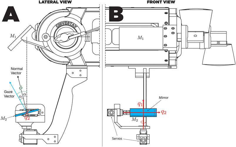
FIGURE 5. Lateral (A) and frontal (B) view schemes of the mirror system.
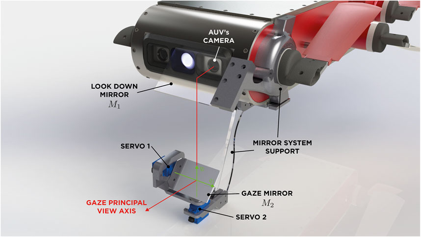
FIGURE 6. Schematic diagram of the structure and degrees of freedom (DOFs) of the gazing mirror.
2.3 Spherical Vision Range, Analysis and Considerations
By varying the pose of
For this case, what really matters is the opposite relation, because the reflection vector in this analysis denotes the gaze vector of the mirror system. To do this, we will define the state of the system (orientation of the virtual camera) as:
There is a direct dependency between the value of θ that describes the azimuthal value of the virtual camera with the value of
where
For rotational joint systems there are no unique inverse kinematics solution and this case is not an exception. In this particular case, the different solutions (set of joint values) can achieve the desired orientation of the virtual camera in the same period (
Physical movement constraint of actuators is not a trivial fact, because as it has been expressed in Eq. 5, the variable θ is only dependent on
Figure 7 assumes an elevation of
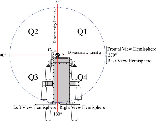
FIGURE 7. Spherical vision range of the mirror system divided in quadrants.
3 Methods
In the previous section, we established a mirror system configuration given a specific platform. We now present the general method for tracking a moving object, which first extracts the visual information provided by the virtual camera and then performs an overall control system to be used for navigation.
3.1 Image Extraction
Due to our AUV’s load capacity, dynamics alteration, camera perspective and other limitations already mentioned, the chosen size of the mirrors may not cover the entire FOV. A guide on how to determine the size is presented in Cortés-Pérez and Torres-Méndez (2016). This fact will cause a scene divided into three main regions, which corresponds to different directions in the vision traces: the regular view region, the passive-mirror view region (
1. Projective geometry: Analytical methods for computing projections by knowing camera calibration parameters.
2. Numerical Methods: These methods included a wide variety of analytical, heuristic, probabilistic, and machine learning methods. Require a training phase for tuning the model numerical parameters.
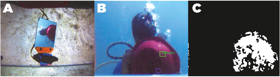
FIGURE 8. Red ball detection using HSV color space linear classification. (A): image acquired in the RGB space. (B): Homography projection of the active mirror region. (C): Color threshold map in the HSV space.
We decided to use a numerical method, but before describing it, we present the reasons for not using an analytical method.
3.1.1 Analytical Methods for Computing Projections
These methods have been extensively studied for 3D vision applications, for both inertial and mobile robotics vision systems, however, calibration of camera parameters in underwater environments is complicated as the light propagation medium changes the geometrical and photometric properties of vision systems (Manley, 2003; Yamashita et al., 2007). Yamashita et al. (2007) describe some of the phenomena of light interaction with the camera along with the propagation properties in the aqueous medium and through the camera lens.
To exemplify how the light direction varies with respect to the camera sensor, several camera calibration tests were performed in our laboratory, using GoPro Hero 4 and Samsung gear 360 2017 (with fisheye lenses) cameras equipped with underwater housings. Both cameras where calibrated using MATLAB camera calibration Toolbox at three different media: air, distilled water and salt water.
In Figure 9, we can observe that in both cases the dimensions of the calibration board change dramatically when entering an aqueous medium, it can also be appreciated that the FOV is reduced.

FIGURE 9. Comparison of two wide angle and fisheye cameras in different propagation medium. (A): wide angle camera on air. (B): wide angle underwater. (C): fisheye camera on air. (D): fisheye camera underwater.
To quantify this alteration, we can review the result of the camera calibration process and compare how parameters vary (see Table 1) in the different media with a concentration of 30 parts per thousand. Note that the focal parameters are noticeably modified as well as the center axis (standing for different radial distortion).
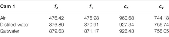
TABLE 1. Camera calibration parameters in different environments.
Regarding the extraction of the corners of our mirror, in order to effectively use an analytical projection method, it is necessary to have an accurate calibration of the actuators, which adds another challenge for the system.
3.1.2 The Nearest Neighbor Method
For the mentioned reasons in the previous section, we use a numerical method to find the corners that define the projection of the active mirror. The method we use for the segmentation is known as “the nearest neighbor.” This method fits in the second category, particularly, in the classification of interpolation statistical methods. The algorithm of the nearest neighbor selects the value of the nearest point and does not consider the values of all the neighboring points of the whole, producing a precise and constant interpolation. The algorithm is simple and is commonly used for 3D rendering.
In this method, N samples of different heights need to be considered, that is, we have N triads
where
In the case of estimating the corners in the active mirror, we have the configuration of the servomotors
To accurately calculate each of the functions, it is necessary to have sufficient and representative information in the training data set covering the entire workspace of the mirror system. Unfortunately, this is impossible to perform it online. However, once the parameters for the regression have been calculated, the interpolation method turns out to be very fast, making it suitable for implementation in real-time applications.
Finally, to extract the visual information enclosed in the quadrant, a homogenous transformation of each of the pixels contained within the convex polygon of interest was performed to obtain an image of constant dimension that represents the rectangular surface of the mirror. In this way, any analysis will be based only on the visual information of the active mirror. Figure 8B shows an example of the projection of the pixels contained in the active mirror by means of the calculated homography matrix.
3.2 Target Detection
In 2015, a contest was launched in Piombino, Italy, for the detection of buoys with underwater robots. Balazs Suto et al. developed a method for the detection of yellow buoys in this contest based on the change of color space (Sütő et al., 2015). It should be noted that in this test the location of buoys was made in the open sea, always having a contrasting color between the blue background and the buoy. However, since our work is oriented toward the exploration of coral reefs, which are environments rich in colors, we decided to have a red ball as our artificial object to be tracked, being red the first frequency that is lost (Sütő et al., 2015), this represented an additional challenge.
There are several algorithms based on pixels, gradients, textures and many other descriptors for object detection in underwater vision systems (Sudhakar and Meena, 2019). Some of the most used methods for circle detection are based on the Hough transform, which require a high computational cost, which translates in a slow performance for a system with limited computational capabilities, as is the case with most the AUVs. Other methods, such as EDCircles, use edge information incorporating edge detectors such as prewire, Sobel and Canny and, although they have been successfully tested for underwater images, they depend on good scene lighting for the effective computation of gradients, which it is not guaranteed at great depths (?).
Given that the object to be tracked is of red color and of circular shape, the key part of the detector is to identify the color of the pixels that belong to the ball. However, due to the photometric properties and light interactions underwater, the “red” color will not be uniform, thus the color detector must be robust to all the range of gradients according to shading. In addition, as the color of the ball will be affected to depth (in the sea), the detector had to be also robust to saturation. Although we know that the target object has a specific geometry, we also know that edge-detection based methods, which use frequency information for compute gradient descriptors (like Canny and Sobel), will have a poor performance compared when they are used in a well lit enviroment (Sudhakar and Meena, 2019). We decided to use the HSV color space similar to the work of Balazs Suto et al, which has proven to have robustness properties for color classification in addition to having a lower computational cost.
Notice that by selecting an appropriate saturation window (S channel), a linear classification with the thresholds of the “red” tones in the hue channel could be made, which would be a complex function if the representation is made in the RGB color space. Therefore, only the homography projection image is processed to detect the red ball, where the color in the HSV space is trimmed with hue values corresponding to the red tone. Figure 8C shows the resulting color threshold map in the HSV space. Then, we use circular-shaped morphological filters of erosion and dilation to reduce possible holes in the binary segmentation mask, thus detecting the least number of red spots in the image. OpenCV tools are used in the image in order to find contours which will delimit color clusters in the image. Then, all possible clusters that could contain a circle are searched, determining its area and its center. The controller will use the information of the centroid of these spots to actively keep the view in it, moving the actuators of the active mirror.
3.3 Colored Spot Clustering
As a measure to reduce the noise of multiple pixel clusters detected, in the control strategy each of the colored spots received from the detection stage are weighted by using its area and location of its centroid. To do this, we made a geometric average considering giving more weight to the spots of greater area for the calculation of a single centroid. The equation that describes this weighting is:
where
Figure 10 shows an example of the centroid estimation when the detector finds two colored spots. In this case, the first spot has an area of 156 pixels and the area in the second spot is 256 pixels. The estimated centroid of the object is shown in the figure with a pink square. It can be seen that the centroid is on the line that joins the centroids of the spots, closer to the right-down region, which is where the stain has the largest area.
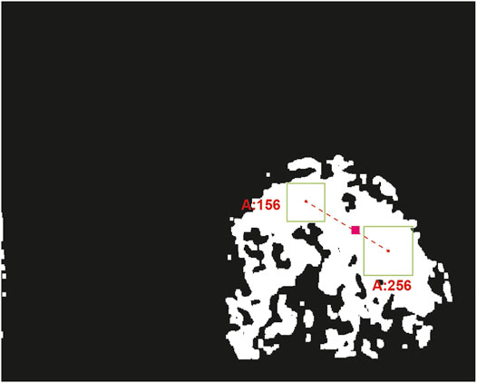
FIGURE 10. Centroid estimation of the ball by pondering all detected clusters. This figure shows a mask where the black pixels represent visual information completely outside the range of colors of the red ball, defined in the HSV color space. The white pixels represent the part of the image that has color information within the established range. The green boxes represent two spots detected. The pink line joins green boxes centroids and the pink box is the estimation of the centroid given to the position and areas of green boxes.
3.4 Kalman Filter
In order to reduce this noise, we incorporate a Kalman filter to estimate the state from the previous measurements, helping to generate references of the object of interest when it leaves the field of vision of the active system. Once the possible centroid of the object has been evaluated this information is used for location of this point on the homography projection image. The Kalman Filter equations are as follows:
where the state of the system at the k-th time instant
which are the centroid coordinates at time k. Also, in Eq. 9, we have that
3.5 Gaze Control
Since the estimation of the object’s centroid is in the image plane, our visual control works by keeping the centroid of the object of interest always on the main optical axis, that is, at the center of the homography transformation. The system error
where
Note also that
where
4 Results
Field experiments were conducted by deploying our underwater platform at 10–12 m of depth in a coral reef environment located in Costa Maya, Mexico. We used the left front camera of the robot to mount our prototype mirror system built of ABS plastic parts printed on a 3D printer (substantially decreasing the cost) to which we add a finishing surface based on automotive paint and ceramic lacquer coat for hardening.
Hi-Tec HS-5086WP digital servomotors were used to generate the roll and pitch movements of the active mirror. These motors have a rotation speed of

FIGURE 11. Photography of the prototype of mirrors mounted in the AUV in the field trials at 10 m deep. The cylindrical module under the robot contains all the control electronics of the mirror system, as well as the communication circuits by means of optical fiber with the robot’s computer.
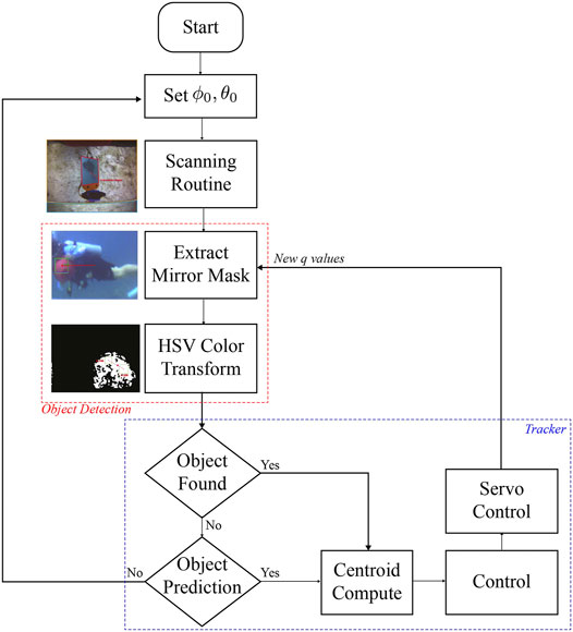
FIGURE 12. Flowchart of the active tracker for experimental trials. The red line frames the process of detecting an object from colored spots in the HSV space. The blue line frames the system control process.
During the execution of the experiments, even though the object to track were lost at some time intervals due to the lighting variations, the active system was able to find it and continue to track it. Error plots and Supplementary Videos show these instants, which are particularly present when the ball is on top of the robot and the view direction points toward the sea surface (sunlight). It is important to mention that in all experiments, the object of interest is being detected despite the high brightness in the scene produced by the Sun, thus resulting in successful experiments despite poor lighting conditions and visibility. A clear limitation of our evaluation framework is not being able to give numerical indicators, since that would require precise knowledge of the trajectory followed of the object with respect to the robot’s position and actuators of our mirror-based active system.
Supplementary Video S1 shows all the stages involved in detection and tracking of the target. First, the image obtained by the robot camera is shown, where the different areas of mirrors
Figure 13 shows the error signals defined in pixels on both axis of the homography image over time for three different experiments, and the corresponding control signals of the servomotors are depicted in Figure 14. The black lines denote the part of the execution where the detector finds an object in the scene. The red lines show the prediction made with the Kalman filter. Note that in Figures 13A, 14A, the purple boxes indicate the time intervals when the detector loses sight of the moving object. However, by using the predictions of the Kalman filter the tracking of the object is recovered (see Supplementary Video S2). In Figures 13B, 14B, the mirror only moves following the prediction information (see Supplementary Video S3). Figures 13C, 14C illustrate circle (ball) detections, however due to poor lighting the tracking becomes impossible (see Supplementary Video S4). The first 30 s of each experiment corresponds to a preliminary routine that verifies functional communication.

FIGURE 13. For each of the three experiments (A,B,C): Reference signals
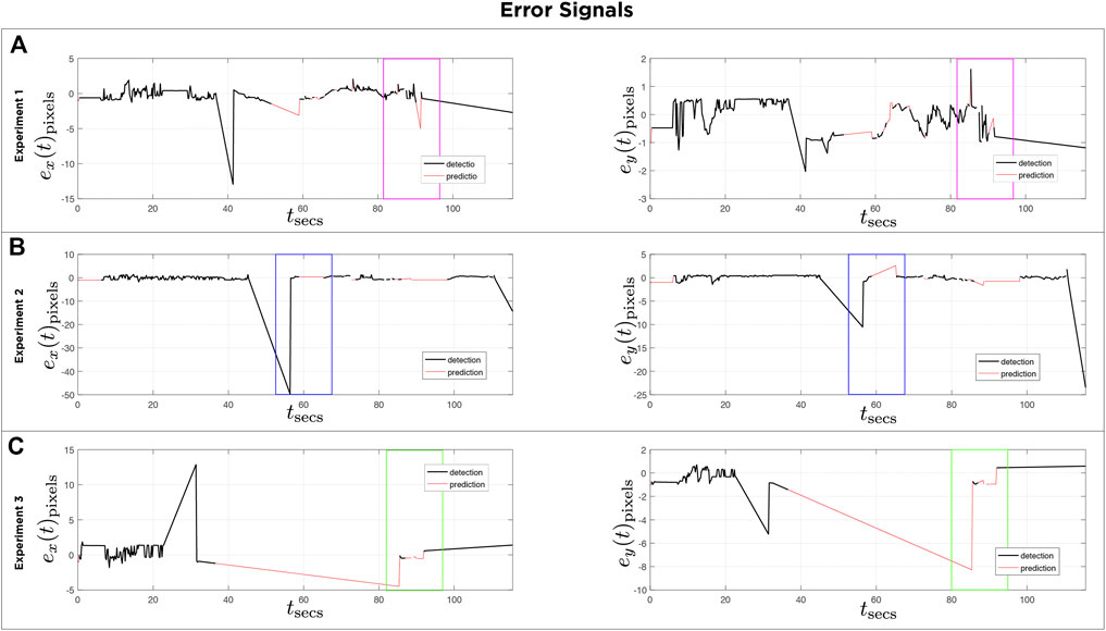
FIGURE 14. For each of the three experiments (A,B,C): Error plots signals
Supplementary Videos S2, S3, S4 show the performance of the system in the field tests. However, by tuning some parameters of the detection algorithm (color threshold and width-height ratio) in offline tests, the detection results improved significantly. Supplementary Video S5 shows a comparison between detection with the original parameters used in the field test and offline detection using different parameters (a greater detection range in the H channel).
5 Conclusion and Future Work
The optic mirror-based system presented has the ability to change the direction of view 360° around the AUV and it can have azimuth elevations to detect objects above the robot in order to perform more complex evasive maneuvers.
Fine-tuning of the controller’s gains will allow rapid change of gaze direction, as the angle of view ratio changes twice as much as the movement of the mirror (reflection properties).
Despite the variation of the hydrodynamic parameters of the system, with a suitable ballasting, the AUV can achieve neutral buoyancy.
The method based on HSV color detection is a functional alternative despite poor lighting conditions, also, it has low computational cost and can be implemented for real-time navigation. The right tuning of the tracker’s parameters for the desired color selection will improve its performance. However, the detection process can be modified according to the task, such as the detection of marine fauna, coral species, free space to navigate, divers, rocks, etc., and easily integrated with the proposed controller (PD), considering that the design of the mirror system makes easy the implementation of simple control laws.
Future work includes path planning strategies using the vision system in closed loop with the robot, to be applied to navigation and exploration schemes already studied. As for the prototype itself, it needs an activation and deactivation mechanism, to be able to integrate it into the robot’s cameras and use its maximum resolution. Another point to improve is the automatic calibration of the mirror system. Since the servomotors were used to make this prototype, there is no direct feedback on the state of the system. In addition, a visual estimate is subject to camera calibration and is still difficult to achieve since for small variations in the system there are small image modifications when the normal to the gaze-mirror
Another important point is the robot’s communication protocol, as one of the design premises was not to make irreversible modifications to the AUV. In the proposed prototype the only available communication port was used: optical fiber Ethernet. In case the AUV had an additional USB port that could be used for data transmission and even activation, the design of the mirror system would be drastically improved, making it more compact, simpler and increasing the autonomy time.
Data Availability Statement
The datasets generated for this study are available on request to the corresponding author.
Author Contributions
This paper has two authors. Both authors made most of contributions: conceptualization, development of theory, validation, verification of the analytical methods, sea trials, formal analysis and investigation, discussion of results and contributed to the final manuscript. Individual contributions follows: performed the computations and software, data curation, visualization, writing original draft preparation, NC; writing review and editing, resources, supervision, project administration, funding acquisition, LT.
Funding
This research was funded by CONACyT Mexico, grant number CB-2013-220540.
Conflict of Interest
The authors declare that the research was conducted in the absence of any commercial or financial relationships that could be construed as a potential conflict of interest.
Acknowledgments
We thank Mar Adentro Diving, Mahahual, for their support during our sea trials.
Supplementary Material
The Supplementary Material for this article can be found online at: https://www.frontiersin.org/articles/10.3389/frobt.2021.542717/full#supplementary-material
References
Agrawal, A., Ramalingam, S., Taguchi, Y., and Chari, V. (2012). “A Theory of Multi-Layer Flat Refractive Geometry,” in 2012 IEEE Conference on Computer Vision and Pattern Recognition, Providence, RI, USA, 16-21 June 2012, 3346–3353. doi:10.1109/CVPR.2012.6248073
Choset, H., Lynch, K., Hutchinson, S., Kantor, G., Burgard, W., Kavraki, L., et al. (2005). Principles of Robot Motion: Theory, Algorithms, and Implementations. Massachusetts: MIT Press.
Cortés-Pérez, N., and Torres-Méndez, L. A. (2016). “A Low-Cost Mirror-Based Active Perception System for Effective Collision Free Underwater Robotic Navigation,” in 2016 IEEE Conference on Computer Vision and Pattern Recognition Workshops (CVPRW), Las Vegas, NV, USA, 26 June-1 July 2016, 61–68. doi:10.1109/CVPRW.2016.15
Erdogan, N., and Yilmaz, K. (2014). “Shifting Colors to Overcome Not Realizing Objects Problem Due to Color Vision Deficiency,” in 2nd Int. Conf. on Advances in Computing, Electronics and Electrical Technology - CEET 2014, Kuala Lumpur, Malaysia, 20 - 21 December, 2014, 11–14.
Georgiades, C., German, A., Hogue, A., Liu, H., Prahacs, C., Ripsman, A., et al. (2004). Aqua: An Underwater Walking Robot. Massachusetts.
Ishibashi, S. (2010). The Low Distortion All-Around View System Using Fisheye Lens for an Underwater Vehicle. OCEANS’10 IEEE SYDNEY, Sydney, NSW, Australia, 24-27 May 2010, 1–5. doi:10.1109/OCEANSSYD.2010.5604027
Lee, K., Lee, C., Kim, S.-A., and Kim, Y.-H. (2012). “Fast Object Detection Based on Color Histograms and Local Binary Patterns,” in TENCON 2012 IEEE Region 10 Conference, Cebu, Philippines, 19-22 Nov. 2012, 1–4. doi:10.1109/TENCON.2012.6412323
Lelais, A., Mahn, J., Narayan, V., Zhang, C., Shi, B. E., and Triesch, J. (2019). Autonomous Development of Active Binocular and Motion Vision through Active Efficient Coding. Front. Neurorobot. 13, 49. doi:10.3389/fnbot.2019.00049
Manley, J. E. (2003). “Autonomous Underwater Vehicles for Ocean Exploration,” in Oceans 2003. Celebrating the Past … Teaming Toward the Future (IEEE Cat. No.03CH37492), San Diego, CA, USA, 22-26 Sept. 2003, 327–331. doi:10.1109/OCEANS.2003.178578
Okumura, K., Ishii, M., Tatsumi, E., Oku, H., and Ishikawa, M. (2013). “Gaze Matching Capturing for a High-Speed Flying Object,” in The SICE Annual Conference 2013, Nagoya, Japan, 14-17 Sept. 2013, 649–654.
Okumura, K., Oku, H., and Ishikawa, M. (2011). “High-speed Gaze Controller for Millisecond-Order pan/tilt Camera,” in 2011 IEEE International Conference on Robotics and Automation, Shanghai, China, 9-13 May 2011, 6186–6191. doi:10.1109/ICRA.2011.5980080
Panda, S., and Nanda, P. K. (2020). Mrf Model-Based Estimation of Camera Parameters and Detection of Underwater Moving Objects. Int. J. Cogn. Inform. Nat. Intelligence (Ijcini) 14, 29. doi:10.4018/ijcini.2020100101
Rongxin Li, R., Haihao Li, H., Weihong Zou, W., Smith, R. G., and Curran, T. A. (1997). Quantitative Photogrammetric Analysis of Digital Underwater Video Imagery. IEEE J. Oceanic Eng. 22, 364–375. doi:10.1109/48.585955
Silvatti, A. P., Cerveri, P., Telles, T., Dias, F. A. S., Baroni, G., and Barros, R. M. L. (2013). Quantitative Underwater 3d Motion Analysis Using Submerged Video Cameras: Accuracy Analysis and Trajectory Reconstruction. Comput. Methods Biomech. Biomed. Eng. 16, 1240–1248. doi:10.1080/10255842.2012.664637
Sudhakar, M., and Meena, M. J. (2019). An Efficient Interactive Segmentation Algorithm Using Color Correction for Underwater Images. Wireless Netw., 1–12. doi:10.1007/s11276-019-02044-0
Suto, B., Dóczi, R., Kalló, J., Takács, B., Várkonyi, T. A., Haidegger, T., and Kozlovszky, M. (2015). “Hsv Color Space Based Buoy Detection Module for Autonomous Underwater Vehicles,” in 2015 16th IEEE International Symposium on Computational Intelligence and Informatics (CINTI), Budapest, Hungary, 19-21 Nov. 2015, 329–332. doi:10.1109/CINTI.2015.7382944
Vidal, E., Palomeras, N., and Carreras, M. (2018). “Online 3d Underwater Exploration and Coverage,” in 2018 IEEE/OES Autonomous Underwater Vehicle Workshop (AUV), Porto, Portugal, 6-9 Nov. 2018, 1–5. doi:10.1109/AUV.2018.8729736
Yahya, M. F., and Arshad, M. R. (2016). “Robust Recognition of Targets for Underwater Docking of Autonomous Underwater Vehicle,” in 2016 IEEE/OES Autonomous Underwater Vehicles (AUV), Tokyo, Japan, 6-9 Nov. 2016, 401–407. doi:10.1109/AUV.2016.7778703
Yamashita, A., Fujii, M., and Kaneko, T. (2007). “Color Registration of Underwater Images for Underwater Sensing with Consideration of Light Attenuation,” in Proceedings 2007 IEEE International Conference on Robotics and Automation, Rome, Italy, 10-14 April 2007, 4570–4575. doi:10.1109/ROBOT.2007.364183
Zelinsky, A. (1992). A mobile Robot Exploration Algorithm. IEEE Trans. Robot. Automat. 8, 707–717. doi:10.1109/70.182671
Keywords: underwater exploration, vision system, object tracking, robot vision, autonomous underwater vehicles, catadioptric system
Citation: Cortés-Pérez N and Torres-Méndez LA (2021) A Mirror-Based Active Vision System for Underwater Robots: From the Design to Active Object Tracking Application. Front. Robot. AI 8:542717. doi: 10.3389/frobt.2021.542717
Received: 13 March 2020; Accepted: 07 June 2021;
Published: 21 June 2021.
Edited by:
Arturo Gomez Chavez, Jacobs University Bremen, GermanyReviewed by:
Alberto Quattrini Li, Dartmouth College, United StatesYunchao Tang, Guangxi University, China
Copyright © 2021 Cortés-Pérez and Torres-Méndez. This is an open-access article distributed under the terms of the Creative Commons Attribution License (CC BY). The use, distribution or reproduction in other forums is permitted, provided the original author(s) and the copyright owner(s) are credited and that the original publication in this journal is cited, in accordance with accepted academic practice. No use, distribution or reproduction is permitted which does not comply with these terms.
*Correspondence: Luz Abril Torres-Méndez, abril.torres@cinvestav.edu.mx