Numerical Study on Water Sealing Effect of Freeze-Sealing Pipe-Roof Method Applied in Underwater Shallow-Buried Tunnel
 Zequn Hong
 Jun Zhang
 Lei Han3
 - 1State Key Laboratory for Geomechanics and Deep Underground Engineering, School of Mechanics and Civil Engineering, China University of Mining and Technology, Xuzhou, China
- 2CCCC Second Highway Consultants Co., Ltd., Wuhan, China
- 3Department of Geotechnical Engineering, Tongji University, Shanghai, China
- 4China Construction Eighth Engineering Division Co., Ltd., Shanghai, China
The freezing-sealing pipe-roof method is a new presupporting technique, which fully combines the advantages of pipe-roof method and artificial ground-freezing method, and can adapt to the construction needs of underground projects in complex and sensitive strata. After the Gongbei Tunnel of Hong Kong–Zhuhai–Macao Bridge, this method will be applied for the first time in an underwater shallow-buried railroad tunnel, and there are still many urgent problems to be solved. In this article, based on the field situation and the preliminary design scheme, a convective heat transfer model under complex boundary conditions was first established. Then, the development of frozen wall thickness during the active freezing period was solved by numerical simulation for three different pipe filling modes, and the cloud map of temperature distribution in the whole section is analyzed. After that, the moving state of river water was characterized by different heat transfer coefficients, and the weakening effect of flow velocity on the top freezing wall was studied. Finally, six critical water sealing paths were selected, and the temperature differences of the frozen curtain were calculated. The results show that the mode with interval concrete filling can form a reliable frozen curtain within the scheduled time, whereas the nonfilling mode cannot achieve the water sealing requirement. River water has a large effect on the temperature at the boundary of jacking pipe and almost no effect on the center of the jacked pipe. It takes approximately 15 days from the frozen soil covering the pipe wall to reach the designed thickness, and the freezing effect of empty pipe lags approximately 28 days compared with that of solid pipe, which requires targeted enhancement measures in field projects.
1 Introduction
The pipe-roof (PR) method is one of the important support methods in the shallow buried excavation construction [1, 2]. It uses micropipe jacking technology to jack in steel pipes around the proposed underground building; the steel pipes are connected with locking ports and injected with waterproof materials to form a watertight underground space, and then the next step of soil reinforcement and excavation is carried out under the protection of the pipe roof [3–5]. Although the use of locking connection can ensure the construction in a water-isolated environment, it requires high precision for the jacking direction of pipe curtain. Long-distance and curved jacking construction often leads to water stop failure due to lack of precision, bringing greater construction risks [6].
The artificial ground-freezing (AGF) method, as a mature and reliable reinforcement technology, has been widely used in coal mines, tunnels, and other municipal projects [7–10]. It uses artificial refrigeration technology to freeze water in the strata and turn the natural soil into frozen soil to increase its strength and stability, whereas the closed frozen curtain acts as an enclosure structure to isolate the groundwater from the excavation works and play a role in water stopping and reinforcement [11]. Therefore, the AGF method is a very reliable choice for reinforcing the gap between adjacent jacking pipes in the PR method, and the resulting new presupport system is known as the freezing-sealing pipe-roof (FSPR) method [12].
As a brand new method, the only project currently using the FSPR method is the famous Gongbei Tunnel of the Hong Kong–Zhuhai–Macao Bridge [13, 14]. Because this project passes under an important entry/exit port, the tunnel construction requires very strict control of surface deformation, so three different types of freezing tubes are innovatively used in the FSPR system. It effectively reduces the damage to the buildings above by the frost heave and thawing settlement effect during the whole freezing process [15, 16]. Unlike this project, when FSPR method is used in shallow-buried tunnel projects under rivers, controlling surface deformation will not be the main purpose of ground presupport. As the weakening of the freezing wall by the high-temperature fluid cannot be ignored, whether a reliable water-sealing curtain can be formed during the freezing process is the first problem to be solved by the FSPR method in a water-rich environment. As there has been no literature about the same problem for FSPR at present, there are still many problems of principle and application in the stage of program demonstration.
Based on the Qinhuai Tunnel in China, which is an underwater railway tunnel to be constructed using the FSPR method for the first time at home and abroad, the critical purpose of FSPR is to reduce the impact of river and groundwater on the tunnel excavation and provide temporary water barrier. In this article, we conducted a series of research on the applicability of this method, especially considering the effect of sealing the moving river flow, to solve the technical problems of FSPR method for water-rich tunnels and provide reference for engineering design and construction.
2 Background
2.1 Engineering Background
The Ning-Wu Railway, then called the Jiangnan Railway, was completed and operated in 1935, connecting Nanjing and Wuhu, which are two important node cities in Jiangsu and Anhui Province. It is a national railway line that undertakes important passenger and freight transportation tasks in the Yangtze River Delta in China. With the rapid development of modern society, the transportation capacity of this ancient single-track nonelectrified railway is mostly saturated, and it has been difficult to meet the needs of urbanization process. At the same time, because the existing Ning-Wu Railway turns around in the Nanjing city, blocking the smooth flow of many main roads, the noise disturbs the nearby residents at night; the progress of the reconstruction project of this railway has been attracting attention for many years.
In recent decades, with the advancement of the construction process, the railway management department and the local government have basically formed a consensus on “using the railway corridor to detour to Nanjing South Station,” which solidifies the external winding scheme of the section from Cangbo Gate Station to Guxiong Station. The rough route diagram is shown in Figure 1. After the completion of this project, it will not only greatly enhance the freight capacity and promote the adjustment of transportation system, but also will effectively improve the living environment and travel conditions of residents along the railway line.
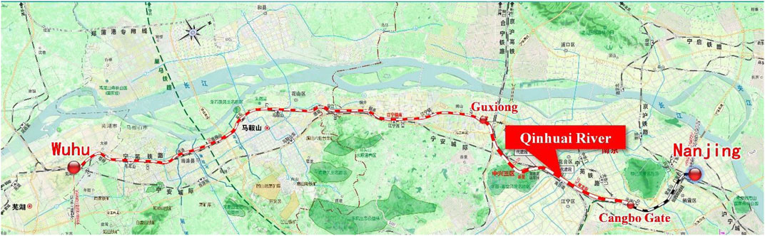
FIGURE 1. Schematic diagram of Ning-Wu Railway reconstruction project.
The preliminary design plan of this route will cross under the New Qinhuai River near Nanjing South Railway Station in the form of an undercut tunnel, and the axis is oblique to the river trend, with an included angle of approximately 41°, as shown in Figure 2. As the thickness of soil covering on the top of the tunnel is very small, and the minimum value is less than 2 m, it does not have the conditions for shield construction. After comparison and selection of construction schemes, it is proposed to adopt the FSPR method as the tunnel presupport system, in which the pipe roof is conducted by jacking 26 steel pipes in sequence to form a load-bearing structure for soil excavation, and freezing tubes are arranged inside the jacking pipes to circulate low-temperature salt water to reduce the soil temperature around the steel jacking pipes. The purpose of FSPR method is to form a closed frozen soil curtain between the jacking pipes to isolate the influence of river water and groundwater on the tunnel construction. The cross section of this tunnel is shown in Figure 3, in which the 26 jacking pipes are arranged approximately in a quasi-rectangular shape along the tunnel excavation contour. The large-size jacked pipe with a diameter of 1.62 m is used as the load-bearing structure, which is also convenient for personnel and equipment to work inside.
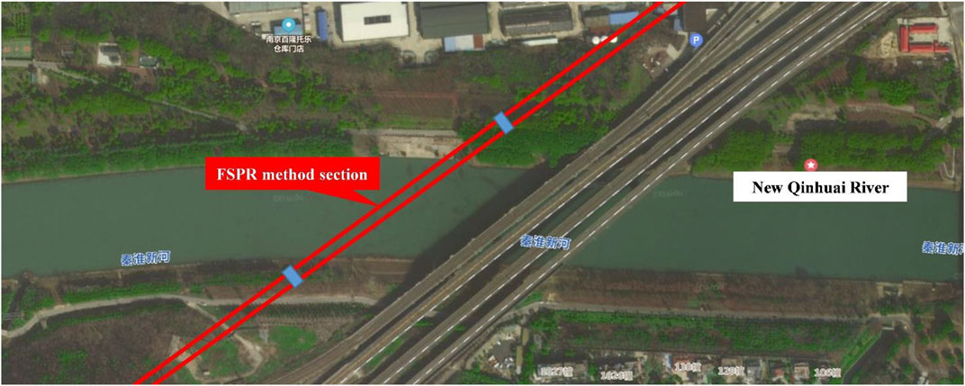
FIGURE 2. Route map of tunnel underneath the Qinhuai River.
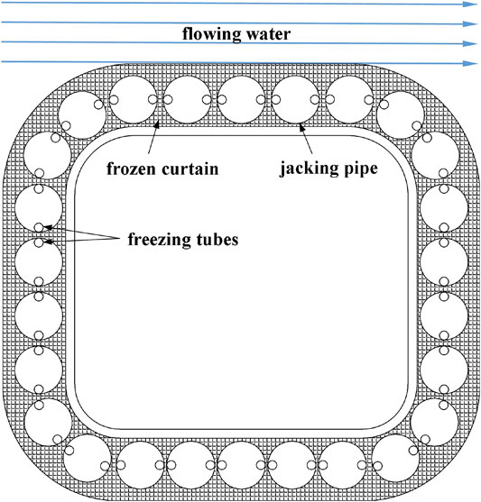
FIGURE 3. Tunnel cross section and recommended layout of freezing tubes.
In addition, as shown in Figure 3, the distance between adjacent jacking pipes is approximately 20 to 25 cm. The gap between adjacent jacking pipes is the main path for groundwater to enter the tunnel excavation surface, and it is also a key location for sealing water using the freezing method. In order to ensure the freezing effect here, the freezers are arranged at the two waists inside each pipe jacking, and the position of the freezing tubes is on the line connecting the centers of adjacent jacked pipes, where the distance between the pipes is the smallest. As the river flow above the tunnel has a nonnegligible weakening effect on the development of the temperature field, whether a reliable freezing wall can be formed to block the influence of groundwater still needs to be systematically studied.
3 Establishment of Numerical Models
3.1 Model Assumptions
In order to make the numerical simulation reflect complex engineering problems, certain model assumptions must be made. The assumptions made in this study mainly include the following three points:
(1) As the project has a small impact area in depth direction, it is assumed that the various layers within the calculation range of the project location are distributed horizontally and are isotropic.
(2) Three-dimensional finite element analysis requires the establishment of complex models, the number of meshes is large, and it takes a long time. Considering that the length of the freezing tube is much larger than its diameter and the axial temperature difference is extremely small, the calculation is carried out by simplifying the three-dimensional finite element model to a two-dimensional model without causing large errors.
(3) Moving water is approximately a fully developed uniform laminar flow, and the water velocity at different depths above the river bed is approximated by an average value.
3.2 Geometric Model
To study the reliability of FSPR method is to study the distribution of ground temperature in the freezing process, because temperature field is the basis of safety evaluation of the frozen curtain. In this study, a two-dimensional heat conduction model considering the full-section pipe jacking is used for calculation according to the design plan of Qinhuai Tunnel, as shown in Figure 4. A total of 26 jacking pipes are arranged in a rectangular shape, and 52 freezing pipes are arranged in a single circle inside the jacking pipe. The dimensions of the jacking pipe and freezing tube in the numerical model are consistent with the actual design scheme. In order to reduce the influence of the boundary conditions of the numerical geometric model on the calculation results during the freezing process, after preliminary calculations, the total length of the model is selected as 67.6 m, and the total height is 52.60 m. The numerical model is symmetrical in the horizontal direction. For the convenience of description, the jacking pipe passing through the top symmetry axis is marked as no. 1 jacking pipe, and the numbering of jacking pipes is 1 to 26, which are numbered clockwise, as shown in Figure 3.
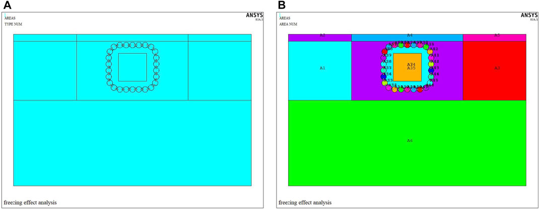
FIGURE 4. Numerical model of full section of Qinhuai Tunnel.
The key point of sealing water using the FSPR method lies in the development of frozen soil curtain, and the analytical results show that the distribution gradient of temperature field decreases as the distance from the freezing pipe increases [15]. Therefore, in order to increase the calculation speed under the premise of satisfying the calculation accuracy, the model grid is divided according to the principle of the denser the grid area near the freezing tube (frozen soil curtain), and the sparser the grid away from the area. The grid division during the active freezing period is shown in Figure 5A, using unstructured triangle element. The region near jacking pipes and freezing tubes have higher grid densities, and the partial enlarged view is shown in Figure 5B. After a period of active freezing, a frozen soil curtain of a certain thickness will be formed around the jacking pipe. When the thickness reaches the design value, it will enter the maintenance freezing stage, and then the tunnel excavation will be carried out. Excavation construction will directly dig out part of the inner frozen soil and reduce the thickness of the frozen wall, and at the same time, the high-temperature thermal disturbance of the excavation surface will also have a greater weakening effect on the frozen wall. In order to simulate the influence of tunnel excavation, it is necessary to remove the soil mesh inside the pipe roof during this process. In this article, we focus on the water sealing performance of the underwater FSPR method during the active freezing period, without analyzing the temperature field variation during the excavation process, and only a simple schematic representation of the numerical meshing is presented here for further research reference. The grid division of the maintenance freezing stage is shown in Figure 5C.
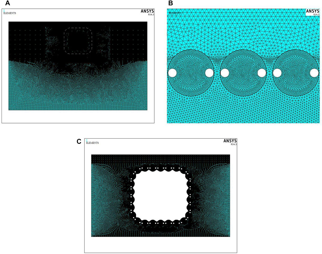
FIGURE 5. Schematic diagram of the grid division of numerical model. (A): Full-section grid. (B): Enlarged view of local grid. (C): Grid after excavation.
3.3 Boundary Conditions and Model Parameters
3.3.1 Geometric Boundary
Proper selection of model boundary conditions is the key to ensuring the reliability of calculation results for numerical simulation [17]. The boundary conditions of the model studied in this article involve the temperature boundary of the freezing tubes, the boundary of the river bed, and the initial temperature boundary of the distant stratum. According to the field situation of the project, convection heat transfer conditions are set between the water and the soil, and the lower boundary of the model is set to a constant temperature of 20°C, which is safer to take this value of the initial soil temperature. Based on the symmetry of the numerical model, the left and right boundaries are set as adiabatic boundaries.
In addition, in order to study the influence of the upper Qinhuai River flow on the frozen soil curtain, considering the existence of convective heat transfer between the frozen soil and the river water, this study applies convective conditions to the river water and soil boundary and uses different heat transfer coefficient to describe the influence of moving water velocity in the following text. The preliminary calculation results show that it is appropriate to set the heat transfer coefficient between the river water and the soil at 50 J/s m2°C, and the river water temperature at 20°C, which is equal to that of initial ground soil.
3.3.2 Boundary of Freezing Tube Wall
For the temperature load on the freezing pipes, the cold capacity of the freezing tube comes from the circulating flow of the internal cryogenic liquid, so the freezing process of the soil is actually the flow of the cryogenic liquid taking away the heat in the ground soil, and the heat exchange at the freezing tube wall is actually a complicated thermal transfer process. However, relevant research shows that the convective heat transfer coefficient of the brine flowing in the freezer is large, and the thermal conductivity of frozen soil is small, which can transform the convective boundary conditions into temperature boundary conditions [18].
At the same time, in the case that the freezing tube is not very long, directly using the inlet temperature of the refrigerant as the constant temperature load on the outer wall of the freezing tube will not cause much errors [19]. Therefore, in this article, the temperature load at the freezing pipe is simplified, and the temperature load is directly applied to the freezing pipe wall without considering the influence of the brine flow in the freezing pipe, and the numerical model is calculated under this condition. Taking into account the field construction, it will take a certain time for the brine temperature to drop to −28°C. Referring to engineering experience, here it takes 7 days to change to −18°C, 11 days to −24°C, and 17 days to −28°C and then maintain this temperature. During the tunnel excavation process, the temperature load is kept at a constant temperature of −28°C during the freezing phase.
3.3.3 Freezing Point and Unfrozen Water Content
Because the thickness of the frozen pipe wall and the diameter of the frozen pipe are much smaller than the entire frozen soil curtain, the focus of the analysis is on the soil freezing process. The properties of the frozen wall are closely related to the freezing temperature of the soil, and this value varies with the salt content of the formation. In this article, referring to the test report on the physical and mechanical properties of the artificially frozen soil in the Yangtze River, the soil freezing temperature is selected as −2.1°C. The relatively low freezing point takes into account the effect of salt content in offshore strata, and this value in Nanjing area is definitely higher, which is also on the safe side for field project. Besides, unfrozen water is the source of liquid water migration in frozen soil, and it is also the main factor that affects the degree of soil particles being cemented by ice. The unfrozen water content in frozen soil maintains a dynamic equilibrium relationship with temperature; that is, as the temperature decreases, the unfrozen water content decreases, and vice versa [20]. This relationship can be expressed by the following formula:
where wu represents the unfrozen water content; wP represents the water content at the plastic limit (%); w0 represents the initial water content (%); A and B are constants related to the properties of the soil; Tf is the absolute value of the temperature (°C); and TP is the absolute value of the freezing temperature at the plastic limit (°C).
According to the experimentally measured freezing point and plastic limit freezing temperature, the constants A and B related to the properties of the soil can be calculated, as shown in Table 1.

TABLE 1. Table of parameters for unfrozen water content test.
Substituting these two constants into Eq. 1 again, then the unfrozen water content at any frozen soil temperature can be calculated. The results of wu (%) at a specific temperature in this article are shown in Table 2.

TABLE 2. Unfrozen water content at different frozen soil temperature (%).
3.3.4 ThermoPhysical Properties
The thermal conductivity of soil is a function of temperature. The thermal conductivity of frozen soil increases slightly with the decrease in negative temperature, but the rate of increase is small [21]. Thus, it is permissible to consider only the freezing and thawing state for the thermal conductivity while ignoring the effect of temperature in general engineering thermal calculations. According to the test results, when the soil temperature is positive, the thermal conductivity is 1.42 W/(mK) and 1.74 W/(mK) when the soil temperature is negative. Other related thermal physical parameters, such as steel jacking pipe, concrete (considering part of the jacking pipe filling concrete), and air, are shown in Table 3.
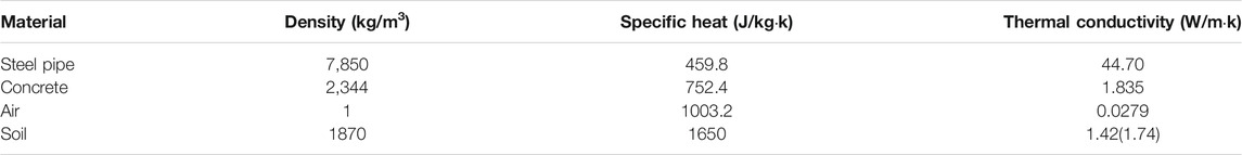
TABLE 3. Thermophysical properties of materials.
4 Results and Discussions
4.1 Freezing Effect Under Different Concrete Filling Modes
In order to improve the heat transfer efficiency between the frozen tubes and the surrounding ground, referring to the experience of filling concrete with steel pipe jacking in previous projects, this article studied the development of the freezing temperature field under three different concrete filling modes. The three filling modes are as follows: Model 1: interval filling with concrete (no. 1 jacking pipe is not filled); Model 2: interval filling with concrete (no. 1 jacking pipe filling); Model 3: no concrete filling.
Taking into account the weakening effect of the freezing effect caused by the moving water at the top of the tunnel, this article analyzed the thickness of frozen curtain at the weak location under the above three modes and draws the change graph of the curtain thickness with time as shown in Figure 6.
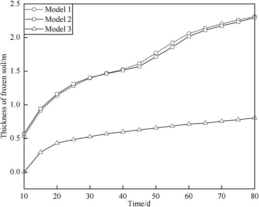
FIGURE 6. The thickness of the frozen soil curtain changes with time.
It can be seen from Figure 6 that the thickness of frozen soil around the top jacking pipe gradually increases with time in all three filling modes, and the development of the interval filling mode is better than that of the no filling mode during the entire active freezing period. Regardless of whether the no. 1 jacking pipe is filled, the development trend of the frozen soil thickness in the interval filling mode is approximately the same. In the early period of active freezing, the development speed of frozen soil thickness first increased and then slowed down, and after 45 days, the speed increases again. When frozen for 60 days, the thickness of the frozen soil reached 2 m and then gradually decreased.
Compared with the interval filling mode, the frozen soil thickness of the unfilled concrete mode only increased rapidly in the early 20 days in active freezing period, and the growth rate of the frozen thickness has been in a very slow state of development afterwards. The thickness of frozen soil in the weak area during the whole 80-day active freezing process was 0.806 m, which was not enough to reach the design index of freezing thickness.
4.2 Changes in Temperature Cloud Chart
In order to more intuitively display the development of the full-section freezing temperature field, draw a cloud map of the frozen soil curtain for the 20th, 40th, 60th, and 80th days under the three filling modes, as shown in Figures 7, 8.
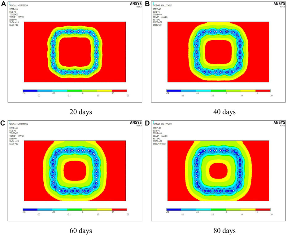
FIGURE 7. Temperature cloud map of interval filling (take mode 1 as an example): (A) 20 days, (B) 40 days, (C) 60 days, and (D) 80 days.
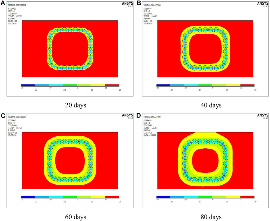
FIGURE 8. Temperature cloud map of no filling: (A) 20 days, (B) 40 days, (C) 60 days, and (D) 80 days.
For the interval filling mode, it can be seen from Figure 7 that during the entire 80-day active freezing period, temperature distribution of the empty jacking pipe is slightly worse than that of the adjacent solid pipe, but with the extension of the freezing time, the blue area representing low temperature gradually increases near the empty pipe. After 80 days of freezing, the section of the empty pipe has been completely covered by blue area, the thickness of frozen soil between adjacent jacking pipes is almost the same as the pipe diameter, and the full section of the tunnel is wrapped by a closed frozen curtain ring to achieve the purpose of sealing groundwater.
Figure 8 shows the cloud diagram of temperature field without filling concrete. It can be seen that during the active freezing period, although the soil temperature around the pipe roof decreases, the temperature in the whole process remains above the freezing point, which is not enough to form a stable and reliable closed frozen curtain. Therefore, this mode cannot achieve the purpose of sealing water between the jacking pipes.
4.3 Influence of Moving Water Boundary
In order to analyze the influence of the river water flow above the tunnel on the freezing effect of the pipe curtain, the heat transfer coefficient between the flowing water and the surface of the river bed is used to characterize the weakening of the frozen soil curtain by different dynamic water velocities. The heat transfer coefficient is positively related to the water flow velocity, and the larger the heat transfer coefficient, the faster the river flows.
Convective conditions on the upper boundary of the model were set, and the coefficients of convective heat transfer were selected as 500, 1,000, and 2,000 J/s m2°C, respectively, according to the heat transfer indexes under the natural convection and forced convection conditions of water. The temperature curve of two characteristic points with time was plotted, namely, the center point and boundary point of no. 1 jacking pipe at the top, as shown in Figure 9.
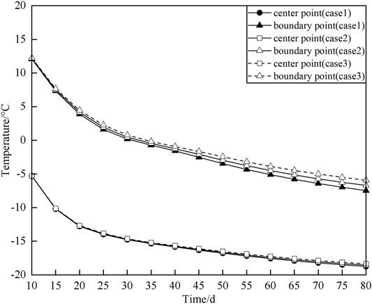
FIGURE 9. Temperature curves under different water flow speed conditions.
It can be seen from the figure that, considering the thermal disturbance of the moving water above the tunnel, the temperature distribution at the top of no. 1 jacking pipe, that is, the point closest to the moving water boundary, is much higher than the center point, with a temperature difference of approximately 5°C. At the same time, it can be found that the temperature curve at the center position of the jacking pipe still almost overlaps under the conditions of three different flow speeds of dynamic water characterized by three heat transfer coefficients, whereas the temperature curves at the upper boundary of the jacking pipe deviate, and the magnitude of deviation varies with the extension of the freezing time increases. This indicates that the river water velocity above the tunnel has little effect on the internal temperature field distribution of the jacking pipe, whereas it has a greater effect on the temperature near the pipe boundary.
4.4 Frozen Soil Thickness of Critical Path for Sealing Water
Taking the interval filling mode 1 as the object of analysis, six critical water sealing paths as shown in Figure 10 were selected for the study of frozen curtain thickness according to the temperature cloud of the unfilled no. 1 jacking pipe.
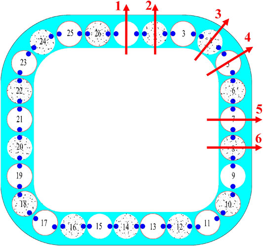
FIGURE 10. Schematic diagram of six critical paths of frozen curtain.
As mentioned before, the distribution of temperature field in the active freezing stage can be obtained after numerical calculation. Based on the previous engineering experience and the possible design thickness of this project, the research nodes are set as follows: the thickness of the frozen curtain reaches 1.61 m (i.e., just flush with the top pipe); the thickness of the frozen soil curtain reaches 2.0 m. For mode 1 with spaced-fill concrete, the temperature clouds for each critical calculation path when the frozen soil thickness reaches these two nodes mentioned previously are shown in Figures 11, 12.
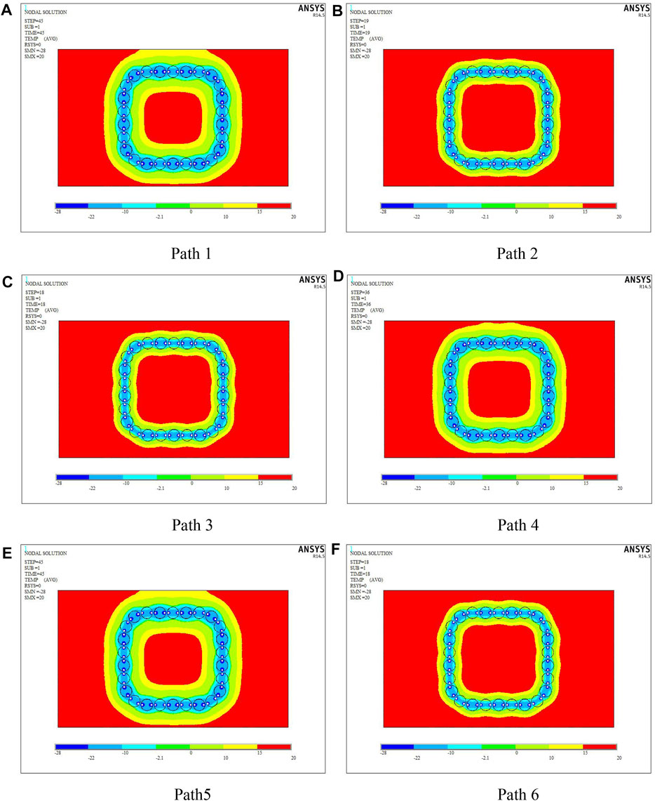
FIGURE 11. Temperature clouds when the thickness reaches 1.61 m for each path: (A) Path 1, (B) Path 2, (C) Path 3, (D) Path 4, (E) Path 5, (F) Path 6.
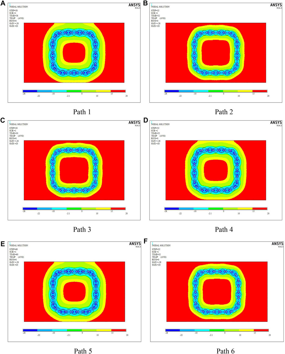
FIGURE 12. Temperature clouds when the thickness reaches 2.0 m for each path: (A) Path 1, (B) Path 2, (C) Path 3, (D) Path 4, (E) Path 5, (F) Path 6.
In order to visually quantify the development of the frozen soil on different paths, the relationship between freezing time and frozen curtain thickness was extracted from the numerical calculation results, and the time to reach two different thickness indicators in each path direction and the corresponding time difference results are shown in Table 4.

TABLE 4. Relationship between freezing time and thickness of frozen curtain.
From the results in the Table 4, it can be seen that the freezing arrangement of no. 1 pipe filling concrete can fully achieve the required effective frost curtain thickness with the aforementioned model parameters, and the time difference from the frozen soil covering the pipe wall to the design thickness is approximately 15 days. In addition, the time required to reach the same frozen curtain thickness is approximately 28 days faster for a concrete-filled pipe than for an empty pipe. In order to reduce the difference in the properties of the local frost curtain and to shorten the time difference between the solid top pipe and the empty pipe to reach the same thickness, specific insulation treatment must be applied to the empty top pipe to enhance the freezing effect in the field construction process.
5 Conclusion
Combined with the practical situation of the FSPR method applied in the railway tunnel under the New Qinhuai River, based on two-dimensional full-section finite element numerical model, we can conclude that under the influence of river moving water, the scheme of using the concrete filling at intervals can form a reliable freezing and sealing curtain within the designed time. The river moving water has a large influence on the boundary temperature of the top jacking pipe, and in order to ensure that the thickness of the top frozen curtain reaches the target index, the freezing pipe temperature in this area can be reduced appropriately. Freezing effect of jacking pipe without filling concrete has a certain gap compared with the solid pipe, so it is necessary to insulate the empty pipe to achieve local strengthening in the field project.
Data Availability Statement
The original contributions presented in the study are included in the article/Supplementary Material, further inquiries can be directed to the corresponding author.
Author Contributions
Writing-original draft preparation, ZH; methodology, JZ and LH; software, YW; All authors have read and agreed to the published version of the article.
Funding
This research was supported by the National Natural Science Foundation of China (no. 52108386). The authors are deeply indebted to the financial support.
Conflict of Interest
Author JZ is employed by CCCC Second Highway Consultants Co., Ltd., and author YW is employed by China Construction Eighth Engineering Division Co. Ltd.
The remaining authors declare that the research was conducted in the absence of any commercial or financial relationships that could be construed as a potential conflict of interest.
Publisher’s Note
All claims expressed in this article are solely those of the authors and do not necessarily represent those of their affiliated organizations, or those of the publisher, the editors and the reviewers. Any product that may be evaluated in this article, or claim that may be made by its manufacturer, is not guaranteed or endorsed by the publisher.
References
1. Hisatake M, Ohno S. Effects of Pipe Roof Supports and the Excavation Method on the Displacements above a Tunnel Face. Tunnelling Underground Space Technology (2008) 23(2):120–7. doi:10.1016/j.tust.2007.02.002
2. Ma P, Shimada H, Sasaoka T, Hamanaka A, Dintwe TKM, Pan D. Investigation on the Performance of Pipe Roof Method Adjacent to the Underground Construction. Geotech Geol Eng (2021) 39(6):4677–87. doi:10.1007/s10706-021-01766-3
3. Li Y, Zhang Y, Li W. Research and Application of Pipe Roofing Method in Soft Soil. Chin J Underground Space Eng (2011) 05:962–7. doi:10.1016/j.cnsns.2011.01.018
4. Zhou S, Wang Y, Huang X. Experimental Study on the Effect of Injecting Slurry inside a Jacking Pipe Tunnel in silt Stratum. Tunnelling Underground Space Technology (2009) 24(4):466–71. doi:10.1016/j.tust.2008.11.003
5. Shou K, Yen J, Liu M. On the Frictional Property of Lubricants and its Impact on Jacking Force and Soil-Pipe Interaction of Pipe-Jacking. Tunnelling Underground Space Technology (2010) 25(4):469–77. doi:10.1016/j.tust.2010.02.009
6. Li W. Study on Application of Pipe-Roof Method to Environmental protection. Building Construction (2011) 33(3):229–31. doi:10.3969/j.issn.1004-1001.2011.03.025
7. Alzoubi MA, Nie-Rouquette A, Ghoreishi-Madiseh SA, Hassani FP, Sasmito AP. On the Concept of the Freezing-On-Demand (FoD) in Artificial Ground Freezing for Long-Term Applications. Int J Heat Mass Transfer (2019) 143:118557. doi:10.1016/j.ijheatmasstransfer.2019.118557
8. Russo G, Corbo A, Cavuoto F, Autuori S. Artificial Ground Freezing to Excavate a Tunnel in sandy Soil. Measurements and Back Analysis. Tunnelling Underground Space Technology (2015) 50:226–38. doi:10.1016/j.tust.2015.07.008
9. Hu X, Hong Z, Fang T. Analytical Solution to Steady-State Temperature Field with Typical Freezing Tube Layout Employed in Freeze-Sealing Pipe Roof Method. Tunnelling Underground Space Technology (2018) 79:336–45. doi:10.1016/j.tust.2018.06.014
10. Vitel M, Rouabhi A, Tijani M, Guérin F. Modeling Heat Transfer between a Freeze Pipe and the Surrounding Ground during Artificial Ground Freezing Activities. Comput Geotechnics (2015) 63(1):99–111. doi:10.1016/j.compgeo.2014.08.004
11. Pimentel E, Papakonstantinou S, Anagnostou G. Numerical Interpretation of Temperature Distributions from Three Ground Freezing Applications in Urban Tunnelling. Tunnelling Underground Space Technology (2012) 28:57–69. doi:10.1016/j.tust.2011.09.005
12. Hu X, She S. Study of Freezing Scheme in Freeze-Sealing Pipe Roof Method Based on Numerical Simulation of Temperature Field. Wuhan: International Conference on Pipelines and Trenchless Technology (2013). p. 1798–805.
13. Hu X, Fang T, Chen J, Ren H, Guo W. A Large-Scale Physical Model Test on Frozen Status in Freeze-Sealing Pipe Roof Method for Tunnel Construction. Tunnelling Underground Space Technology (2018) 72:55–63. doi:10.1016/j.tust.2017.10.004
14. Hu X, Deng S, Ren H. In Situ Test Study on Freezing Scheme of Freeze-Sealing Pipe Roof Applied to the Gongbei Tunnel in the Hong Kong-Zhuhai-Macau Bridge. Appl Sci (2016) 7(1):27. doi:10.3390/app7010027
15. Hong Z, Hu X, Fang T. Analytical Solution to Steady-State Temperature Field of Freeze-Sealing Pipe Roof Applied to Gongbei Tunnel Considering Operation of Limiting Tubes. Tunnelling Underground Space Technology (2020) 105:103571. doi:10.1016/j.tust.2020.103571
16. Han L, Ye G-l., Li Y-h., Xia X-h., Wang J-h. In Situ monitoring of Frost Heave Pressure during Cross Passage Construction Using Ground-Freezing Method. Can Geotech J (2016) 53:530–9. doi:10.1139/cgj-2014-0486
17. Panteleev I, Kostina A, Plekhov OA Numerical Simulation of Artificial Ground Freezing in a Fluid-Saturated Rock Mass with Account for Filtration and Mechanical Processes. Sci Cold Arid Regions (2017)9:363–377. doi:10.3724/SP.J.1226.2017.00363
18. Li Z, G Z. Field Synergy Theory for Optimizing Convective Heat Transfer. China: Science Press (2010).
19. Yang Z, Che P. Numerical Simulation of Temperature Field of Horizontal Freezing with Single Tube under the Condition of Refrigerant Circulation. Jiangsu Coal (2004) 02:72–3.
20. Li P, Xu X, Chen F. Research Status and Progress of Freezing Margins and Frost Heave Models. J Glaciology Geocryology (2000) 22(1):90–85.
Keywords: underwater tunnel, freeze-sealing pipe roof, temperature field, frozen curtain, freezing effect
Citation: Hong Z, Zhang J, Han L and Wu Y (2022) Numerical Study on Water Sealing Effect of Freeze-Sealing Pipe-Roof Method Applied in Underwater Shallow-Buried Tunnel. Front. Phys. 9:794374. doi: 10.3389/fphy.2021.794374
Received: 13 October 2021; Accepted: 23 November 2021;
Published: 03 January 2022.
Edited by:
Qingxiang Meng, Hohai University, ChinaReviewed by:
Stefano De Leo, State University of Campinas, BrazilChaojun Jia, Central South University, China
Copyright © 2022 Hong, Zhang, Han and Wu. This is an open-access article distributed under the terms of the Creative Commons Attribution License (CC BY). The use, distribution or reproduction in other forums is permitted, provided the original author(s) and the copyright owner(s) are credited and that the original publication in this journal is cited, in accordance with accepted academic practice. No use, distribution or reproduction is permitted which does not comply with these terms.
*Correspondence: Jun Zhang, 619402356@qq.com