Magnetic Skyrmion Generation by Reflective Spin Wave Focusing
 Xianglong Yao
 Zhenyu Wang
 Menghua Deng2
  Yunshan Cao
 Peng Yan
- 1School of Electronic Science and Engineering and State Key Laboratory of Electronic Thin Films and Integrated Devices, University of Electronic Science and Technology of China, Chengdu, China
- 2School of Physics and Electronics, Hunan University, Changsha, China
We propose a method to generate magnetic skyrmions by focusing spin waves totally reflected by a curved film edge. The edge contour is derived to be parabolic and frequency-independent based on the identical magnonic path length principle. We performed micromagnetic simulations to verify our theoretical design. Under proper conditions, the reflected spin waves first converge at the focal point with the enhanced intensity leading to the emergence of magnetic droplets, which are then converted to magnetic skyrmion accompanied by a change in the topological charge. We numerically obtain the phase diagram of skyrmion generation with respect to the amplitude and frequency of the driving field. Our finding would be helpful for the design of spintronic devices combining the advantage of skyrmionics and magnonics.
1 Introduction
Magnetic skyrmions are topologically protected spin textures with a high thermal stability [1, 2]. They normally emerge in chiral bulk magnets or magnetic thin films with broken inversion symmetry, which gives rise to the Dzyaloshinskii–Moriya interaction (DMI) [3, 4]. In contrast to skyrmions, magnons are low-energy excitations in magnetic systems and can be easily generated and destroyed because of their bosonic nature. Both skyrmions and magnons have been extensively investigated and applied in information transmission and procession, which gives birth to two emerging subfields of magnetism: skyrmionics [5–8] and magnonics [9–11].
The interaction between skyrmions and magnons has been widely studied in magnon–skyrmion scattering [12, 13], magnon-driven skyrmion motion [14, 15], skyrmion-based magnonic crystal [16, 17], and skyrmion-induced magnon frequency comb [18]. Recently, the conversion between skyrmions and magnons has been attracting much attention. For example, the spin wave emission is often observed during the annihilation and core switching of magnetic skyrmions [19, 20]. However, it is quite hard to convert magnons to skyrmions because the energy carried by spin waves is much lower than the barrier between the skyrmion and the uniform ferromagnetic state. To create skyrmions by spin waves, the spin wave energy should be accumulated to overcome the energy barrier, which has been realized by the combination of the geometry change and the DMI-induced effective magnetic field [21] and by spin wave focusing [22]. In previous studies, the spin wave focusing is achieved by constructing a spin wave lens, which can be designed by a curved interface [22–24], a local graded-index region [25, 26], and a metasurface [27, 28]. In these methods, the spin wave reflection at the interface would decrease the efficiency of spin wave focusing. In this regard, one should avoid the spin wave reflection as much as possible, intuitively.
However, it is known that the spin wave can transmit through an interface without reflection only in rare cases [29]. On the contrary, spin wave can be completely reflected under more loose conditions, such as at the magnetic–non-magnetic interface. One natural issue is how to accumulate all reflected spin waves. In this study, we design a curved film edge based on the principle of identical magnonic path length, which suggests that the parabolic film edge can focus all reflected spin waves independent of their frequencies. At the focal point, the spin wave intensity can be significantly enhanced and the focal point magnetization oscillates strongly and might even be locally reversed, which is considered as the precursor for the skyrmion formation.
2 Analytical Model
We consider a chiral ferromagnetic film with a curved boundary, which is magnetized along the
where m = M/Ms is the unit magnetization vector with the saturated magnetization Ms, γ is the gyromagnetic ratio, μ0 is the vacuum permeability, and α is the Gilbert damping constant. The effective field Heff comprises the exchange field, the DM field, the anisotropy field, and the dipolar field. In the following discussion, the interfacial DMI is considered.
The film edge for total-reflection focusing can be designed based on the identical magnonic path length (MPL) principle [22]. We first consider a plane spin wave incident from the left source (x = −xs), which is reflected by the film edge and converges into a focal point (−xf, 0), as shown in Figure 1. The identical MPL principle yields the following:
and the edge contour is described as
where p = 2xf . One can see that the shape of the film edge is parabolic for the total-reflection focusing of the plane spin waves.
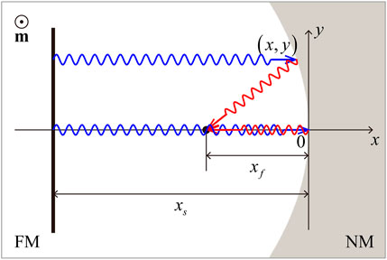
FIGURE 1. Schematic of the film edge for total-reflection focusing of spin waves. The static magnetization m is oriented along the + z direction. FM and NM denote the ferromagnetic and non-magnetic regions, respectively. The black bar located at x = −xs is the spin wave source. A parallel incident spin wave (blue wavy lines with arrow) propagates towards the curved edge, and the reflected spin wave (red wavy lines with arrow) converges on the focal point at x = −xf (black point).
3 Numerical Results and Discussions
To verify our theoretical design, we numerically solve the full LLG equation (Equation 1) using the micromagnetic simulation code MuMax3 [30]. Magnetic parameters of the adopted Co are as follows: Ms = 5.8 × 10⁵ A/m, Aex = 15 pJ/m, D = 2.5 mJ/m2, and Ku = 6 × 10⁵ J/m3. The cell size 2 × 2 × 1 nm3 is used to discretize the film in simulations. The Gilbert damping constant α = 10−3 is used to ensure a long-distance propagation of spin waves, and absorbing boundary conditions are adopted to avoid the spin wave reflection by the film edges except for the curved edge [31].
We first set the focal length as xf = 400 nm in simulations and design a parabolic edge to focus the reflected spin waves. A sinusoidal monochromatic microwave field
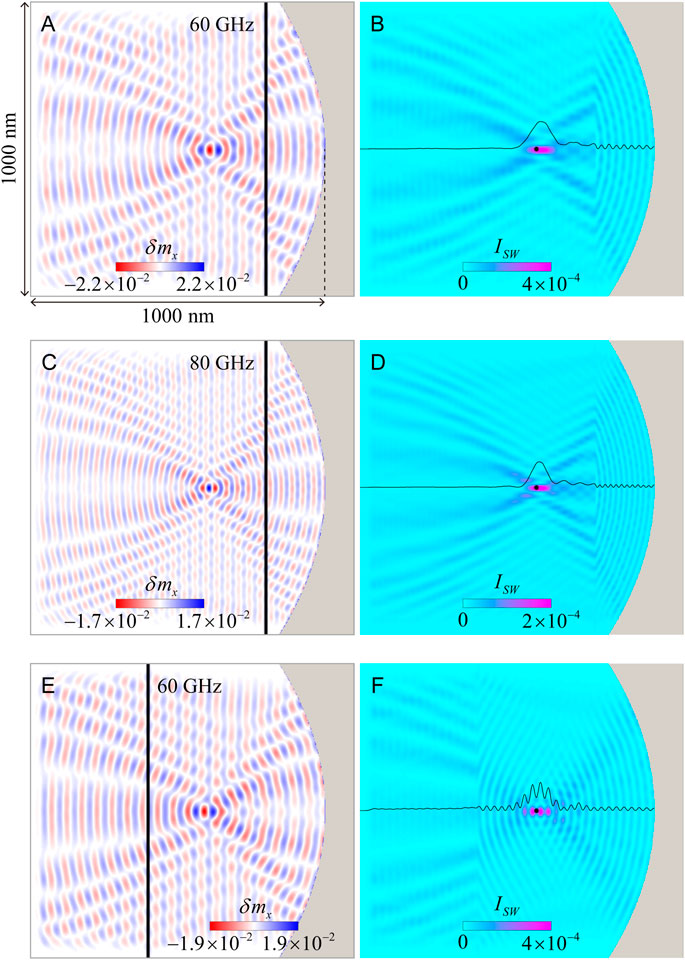
FIGURE 2. (A) Snapshot of the spin waves reflected from the parabolic edge. The spin wave frequency is ω/2π = 60 GHz. The black bar in (A) denotes the spin wave source located at x = −200 nm, which is excited by a microwave field with μ0h0 = 10 mT. (B) The spin wave intensity in (A). The black point represents the ideal position of the focal point. The black curve shows the profile of the spin wave intensity along the x axis at y = 0. (C) and (D) Snapshot of total-reflection focusing of spin waves and the corresponding intensity for ω/2π = 80 GHz. (E) and (F) Snapshot of spin waves and their intensity for the exciting source located at x = −600 nm.
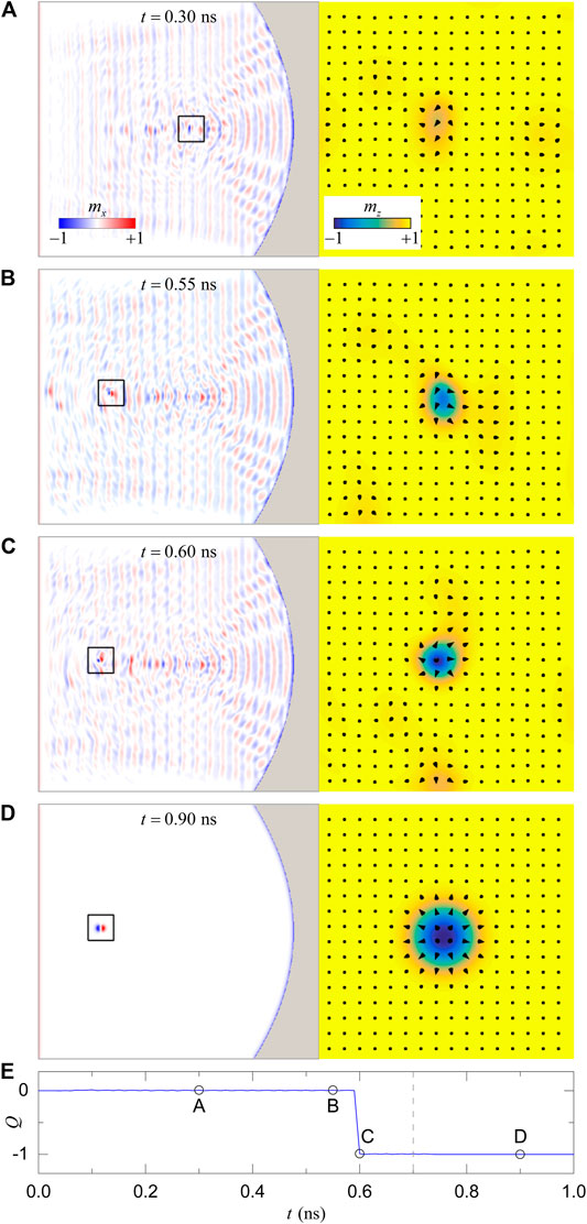
FIGURE 3. The creation process of the magnetic skyrmion induced by the total-reflection focusing. The exciting field with μ0h0 = 360 mT is applied in (A–C) and is turned off in (D). The z-component magnetization of the rectangular area in the left column is enlarged in the right column. (E) Temporal evolution of the topological number Q. The microwave field starts at t = 0 and ends at t = 0.7 ns, indicated by the gray dashed line.
A close inspection shows that there is a sharp kink of the spin wave intensity at the magnon source (Figures 2B,D,F). It results from the change in the coherence of spin waves through the magnon source. On the right side of the magnon source, the emitted spin waves and reflected spin waves are coherent, leading to a strong interference with a significant interference fringe. The phase of the reflected spin wave would change when it propagates through the magnon source. The coherence between the reflected and emitted spin waves on the left side is destroyed, which shows a slight fluctuation in the spin wave intensity. Different fluctuations in spin wave intensities on both sides of the magnon source induce a sharp kink. Therefore, the spin wave intensity at the focal point would fluctuate drastically when the magnon source is located at the left side of the focal point, as shown in Figures 2E,F. This severe fluctuation of the spin wave intensity would destroy the localized spin wave soliton (droplet) around the focal point, which hinders the generation of skyrmion. In what follows, we focus on the case of the magnon source locating at the right side of the focal point for generating skyrmion by spin wave focusing.
To generate magnetic skyrmions, we increase the amplitude of the microwave field to μ0h0 = 360 mT. The spin wave intensity around the focal point is enhanced significantly, which shows a strong magnetization oscillation, as plotted in Figure 3A. With the continuous excitation of spin waves, more energy is harvested, leading to the local switching of the magnetization and the formation of magnetic droplets, which can be easily driven by spin waves (Figure 3B). The magnetic droplet is a non-topological localized spin wave soliton [32, 33] and is unstable in a chiral ferromagnetic film because of high DMI energy. Under the disturbance of spin waves, the magnetic droplet is converted to a dynamical skyrmion at t = 0.6 ns, as shown in Figure 3C. Then, we turn off the microwave field at t = 0.7 ns and the system is relaxed toward an equilibrium state with a stable skyrmion state (Figure 3D). Moreover, it is noted that the skyrmion is not created exactly at the focal point. This is because the first nucleated droplet driven by spin waves moves faster than the skyrmion during which the transformation from the droplet to skyrmion happens. This would lead to the skyrmion nucleation site developing far away from the focal point.
The topological charge, which is given by
can be used to characterize the topology of skyrmions in two-dimensional systems. However, the large spatial variations of m in the process of the skyrmion nucleation and annihilation reduce the accuracy of the finite difference approximation of Eq. 4 and result in non-integer values of Q [22]. To avoid this spurious deviation, we follow the definition of the topological charge given by Berg and Lüscher [34], which is expressed as
with
where qijk is the local topological charge density of elementary-signed triangles, which is invariant under a cyclic permutation of the indices ijk. This lattice-based approach has been employed in quantifying the topological charge in micromagnetics recently [35–37]. Based on this scheme, we calculate the time evolution of the topological charge Q in the process of the skyrmion generation (Figure 3E), where nonphysical values of Q are excluded. An abrupt change in Q from 0 to −1 is observed at t = 0.6 ns, which confirms the skyrmion creation.
From the generation process of the skyrmion, one can see that the magnetic droplet is an indispensable intermediate between ferromagnetic and skyrmion states. Although the energy of the magnetic droplet is higher than the skyrmion, the skyrmion cannot be created directly from the ferromagnetic state. This is because the droplet is non-topological and can be transformed continuously from a ferromagnetic state. However, the continuous transformation from a ferromagnetic state to the skyrmion state is highly unlikely, which is due to the topological protection of the skyrmion. Compared to the droplet, a change in the topological charge is accompanied for the skyrmion creation, which requires more energy input from the external driving.
Figure 4A plots the nucleation time of the first skyrmion
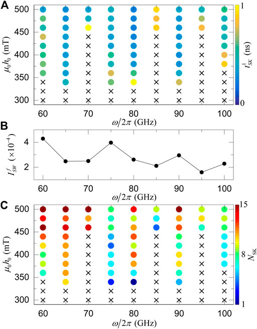
FIGURE 4. (A) The nucleation time of the first skyrmion
The above micromagnetic simulations are all performed for the idealized edge, which is often not the case in practical applications, due to edge roughness. To make the roughness effect on the total-reflection focusing clear, we performed additional simulations with random roughness, which is close to the rough edge in real cases. For the roughness amplitude Ar = 6 nm, the reflected spin waves with 60 GHz can be well focused with a reduced intensity (≈81%), as shown in Figures 5A,B. With the increase in Ar, the focal point intensity of spin waves
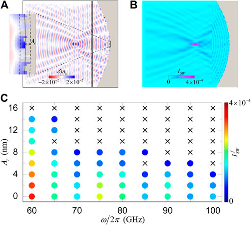
FIGURE 5. (A) Snapshot of spin waves reflected from the parabolic edge with a random roughness, which is depicted by the formula x = −y2/(4xf) + ArIr, where Ar is the roughness amplitude and Ir is a random value in the interval (−1, 1). The black bar shows the exciting source of spin waves with μ0h0 = 10 mT and ω/2π = 60 GHz. The enlarged image of the rectangular area is shown on the left. The solid line in the inset denotes the ideal parabolic edge, and the dashed lines show the amplitude of the roughness (Ar = 6 nm). (B) The spin wave intensity in (A). (C) Phase diagram of the spin wave intensity at the focal point as a function of the roughness amplitude and the spin wave frequency. The black crosses represent no spin wave focusing, and the colored dots are the spin wave intensity.
The results in this study are obtained in magnetic metals, which usually have high perpendicular magnetic anisotropy and high damping. A large-amplitude microwave field is needed for the skyrmion creation, which is difficult to achieve in experiments. Fortunately, magnetic insulators with perpendicular anisotropy and ultra-low damping have been demonstrated to host skyrmions [39–41], which makes our method more applicable from the view of materials realizations. In a previous study, we proposed a method to generate skyrmion by focusing the transmitted spin waves, which is realized by constructing a spin wave lens with a curved interface [22]. The shape of the interface depends on the relative refraction index of spin waves, which is frequency-dependent. Thus, that method is only feasible for focusing spin waves with one certain frequency. For spin wave focusing with a different frequency, a new curved interface should be designed, which hinders the practical application of that method. We, therefore, believe that the total-reflection focusing in the present study provides a promising way to generate the skyrmion.
4 Conclusion
In summary, we theoretically investigated the skyrmion generation induced by the total-reflection focusing of spin waves. The shape of the film edge was derived based on the identical magnonic path length principle. Micromagnetic simulations were performed to confirm the focusing effect of spin waves reflected from the parabolic edge. By increasing the field amplitude, we observed the nucleation of magnetic droplet induced by the total-reflection focusing and the transformation to the skyrmion with a change in the topological charge. Our results provide a method to generate skyrmion by reflective focusing of spin waves, which is frequency-independent and would promote the development and application of spintronic devices combing magnons and skyrmions.
Data Availability Statement
The original contributions presented in the study are included in the article/Supplementary Material; further inquiries can be directed to the corresponding authors.
Author Contributions
ZW and PY conceived the idea and wrote the paper. ZW and XY finished the analytical deduction and performed all the simulations. MD, Z-XL, ZZ, and YC corrected the paper and discussed.
Funding
This work was supported by the National Natural Science Foundation of China (Grants No. 12074057 and No. 11704060). ZW acknowledges financial support from the China Postdoctoral Science Foundation (Grant No. 2019M653063). Z-XL acknowledges financial support from the China Postdoctoral Science Foundation (Grant No. 2019M663461) and the NSFC (Grant No. 11904048). ZZ acknowledges financial support from the China Postdoctoral Science Foundation (Grant No. 2020M673180).
Conflict of Interest
The authors declare that the research was conducted in the absence of any commercial or financial relationships that could be construed as a potential conflict of interest.
Publisher’s Note
All claims expressed in this article are solely those of the authors and do not necessarily represent those of their affiliated organizations, or those of the publisher, the editors, and the reviewers. Any product that may be evaluated in this article, or claim that may be made by its manufacturer, is not guaranteed or endorsed by the publisher.
Acknowledgments
We thank H. Yang and L. Song for helpful discussions.
References
1. Wild J, Meier TNG, Pöllath S, Kronseder M, Bauer A, Chacon A, et al. Entropy-limited Topological protection of Skyrmions. Sci Adv (2017) 3:e1701704. doi:10.1126/sciadv.1701704
2. Desplat L, Suess D, Kim J-V, Stamps RL. Thermal Stability of Metastable Magnetic Skyrmions: Entropic Narrowing and Significance of Internal Eigenmodes. Phys Rev B (2018) 98:134407. doi:10.1103/PhysRevB.98.134407
3. Dzyaloshinsky I. A Thermodynamic Theory of “Weak” Ferromagnetism of Antiferromagnetics. J Phys Chem Sol (1958) 4:241–55. doi:10.1016/0022-3697(58)90076-3
4. Moriya T. Anisotropic Superexchange Interaction and Weak Ferromagnetism. Phys Rev (1960) 120:91–8. doi:10.1103/PhysRev.120.91
5. Nagaosa N, Tokura Y. Topological Properties and Dynamics of Magnetic Skyrmions. Nat Nanotech (2013) 8:899–911. doi:10.1038/nnano.2013.243
6. Fert A, Cros V, Sampaio J. Skyrmions on the Track. Nat Nanotech (2013) 8:152–6. doi:10.1038/nnano.2013.29
8. Zhang X, Zhou Y, Mee Song K, Park T-E, Xia J, Ezawa M, et al. Skyrmion-electronics: Writing, Deleting, reading and Processing Magnetic Skyrmions toward Spintronic Applications. J Phys Condens Matter (2020) 32:143001. doi:10.1088/1361-648x/ab5488
9. Serga AA, Chumak AV, Hillebrands B. YIG Magnonics. J Phys D: Appl Phys (2010) 43:264002. doi:10.1088/0022-3727/43/26/264002
10. Lenk B, Ulrichs H, Garbs F, Münzenberg M. The Building Blocks of Magnonics. Phys Rep (2011) 507:107–36. doi:10.1016/j.physrep.2011.06.003
11. Chumak AV, Vasyuchka VI, Serga AA, Hillebrands B. Magnon Spintronics. Nat Phys (2015) 11:453–61. doi:10.1038/nphys3347
12. Iwasaki J, Beekman AJ, Nagaosa N. Theory of Magnon-Skyrmion Scattering in Chiral Magnets. Phys Rev B (2014) 89:064412. doi:10.1103/PhysRevB.89.064412
13. Schütte C, Garst M. Magnon-skyrmion Scattering in Chiral Magnets. Phys Rev B (2014) 90:094423. doi:10.1103/PhysRevB.90.094423
14. Zhang X, Müller J, Xia J, Garst M, Liu X, Zhou Y. Motion of Skyrmions in Nanowires Driven by Magnonic Momentum-Transfer Forces. New J Phys (2017) 19:065001. doi:10.1088/1367-2630/aa6b70
15. Jiang Y, Yuan HY, Li Z-X, Wang Z, Zhang HW, Cao Y, et al. Twisted Magnon as a Magnetic Tweezer. Phys Rev Lett (2020) 124:217204. doi:10.1103/physrevlett.124.217204
16. Ma F, Zhou Y, Braun HB, Lew WS. Skyrmion-based Dynamic Magnonic crystal. Nano Lett (2015) 15:4029–36. doi:10.1021/acs.nanolett.5b00996
17. Moon KW, Chun BS, Kim W, Hwang C. Control of Spin-Wave Refraction Using Arrays of Skyrmions. Phys Rev Appl (2016) 6:064027. doi:10.1103/physrevapplied.6.064027
18. Wang Z, Yuan HY, Cao Y, Li Z-X, Duine RA, Yan P. Magnonic Frequency Comb through Nonlinear Magnon-Skyrmion Scattering. Phys Rev Lett (2021) 127:037202. doi:10.1103/PhysRevLett.127.037202
19. Zhang X, Xia J, Zhou Y, Liu X, Zhang H, Ezawa M. Skyrmion Dynamics in a Frustrated Ferromagnetic Film and Current-Induced Helicity Locking-Unlocking Transition. Nat Commun (2017) 8:1717. doi:10.1038/s41467-017-01785-w
20. Zhang B, Wang W, Beg M, Fangohr H, Kuch W. Microwave-induced Dynamic Switching of Magnetic Skyrmion Cores in Nanodots. Appl Phys Lett (2015) 106:102401. doi:10.1063/1.4914496
21. Liu Y, Yin G, Zang J, Shi J, Lake RK. Skyrmion Creation and Annihilation by Spin Waves. Appl Phys Lett (2015) 107:152411. doi:10.1063/1.4933407
22. Wang Z, Li Z-X, Wang R, Liu B, Meng H, Cao Y, et al. Spin-wave Focusing Induced Skyrmion Generation. Appl Phys Lett (2020) 117:222406. doi:10.1063/5.0029401
23. Toedt J-N, Mundkowski M, Heitmann D, Mendach S, Hansen W. Design and Construction of a Spin-Wave Lens. Sci Rep (2016) 6:33169. doi:10.1038/srep33169
24. Bao W, Wang Z, Cao Y, Yan P. Off-axial Focusing of a Spin-Wave Lens in the Presence of Dzyaloshinskii-Moriya Interaction. Phys Rev B (2020) 102:014423. doi:10.1103/PhysRevB.102.014423
25. Whitehead NJ, Horsley SAR, Philbin TG, Kruglyak VV. A Luneburg Lens for Spin Waves. Appl Phys Lett (2018) 113:212404. doi:10.1063/1.5049470
26. Vogel M, Pirro P, Hillebrands B, von Freymann G. Optical Elements for Anisotropic Spin-Wave Propagation. Appl Phys Lett (2020) 116:262404. doi:10.1063/5.0018519
27. Zelent M, Mailyan M, Vashistha V, Gruszecki P, Gorobets OY, Gorobets YI, et al. Spin Wave Collimation Using a Flat Metasurface. Nanoscale (2019) 11:9743–8. doi:10.1039/C8NR10484K
28. Gräfe J, Gruszecki P, Zelent M, Decker M, Keskinbora K, Noske M, et al. Direct Observation of Spin-Wave Focusing by a Fresnel Lens. Phys Rev B (2020) 102:024420. doi:10.1103/PhysRevB.102.024420
29. Yan P, Wang XS, Wang XR. All-magnonic Spin-Transfer Torque and Domain wall Propagation. Phys Rev Lett (2011) 107:177207. doi:10.1103/physrevlett.107.177207
30. Vansteenkiste A, Leliaert J, Dvornik M, Helsen M, Garcia-Sanchez F, Van Waeyenberge B. The Design and Verification of Mumax3. AIP Adv (2014) 4:107133. doi:10.1063/1.4899186
31. Venkat G, Fangohr H, Prabhakar A. Absorbing Boundary Layers for Spin Wave Micromagnetics. J Magnetism Magn Mater (2018) 450:34–9. Perspectives on magnon spintronics. doi:10.1016/j.jmmm.2017.06.057
32. Chaves-O'Flynn GD, Stein DL. Thermal Activation Barriers for Creation and Annihilation of Magnetic Droplet Solitons in the Presence of Spin Transfer Torque. Phys Rev B (2020) 101:184421. doi:10.1103/PhysRevB.101.184421
33. Macià F, Kent AD. Magnetic Droplet Solitons. J Appl Phys (2020) 128:100901. doi:10.1063/5.0018251
34. Berg B, Lüscher M. Definition and Statistical Distributions of a Topological Number in the Lattice O(3) σ-model. Nucl Phys B (1981) 190:412–24. doi:10.1016/0550-3213(81)90568-X
35. Böttcher M, Heinze S, Egorov S, Sinova J, Dupé B. B-T Phase Diagram of Pd/Fe/Ir(111) Computed with Parallel Tempering Monte Carlo. New J Phys (2018) 20:103014. doi:10.1088/1367-2630/aae282
36. Müller GP, Hoffmann M, Dißelkamp C, Schürhoff D, Mavros S, Sallermann M, et al. Spirit : Multifunctional Framework for Atomistic Spin Simulations. Phys Rev B (2019) 99:224414. doi:10.1103/PhysRevB.99.224414
37. Kim J-V, Mulkers J. On Quantifying the Topological Charge in Micromagnetics Using a Lattice-Based Approach. IOP SciNotes (2020) 1:025211. doi:10.1088/2633-1357/abad0c
38. Yu X, Kagawa F, Seki S, Kubota M, Masell J, Yasin F, et al. Real-space Observations of 60-nm Skyrmion Dynamics in an Insulating Magnet under Low Heat, Nat Commun (2021) 12:5079. PREPRINT (Version 1) available at Research Square doi:10.1038/s41467-021-25291-2
39. Soumah L, Beaulieu N, Qassym L, Carrétéro C, Jacquet E, Lebourgeois R, et al. Ultra-low Damping Insulating Magnetic Thin Films Get Perpendicular. Nat Commun (2018) 9:3355. doi:10.1038/s41467-018-05732-1
40. You C-Y. Skyrmions in Magnetic Insulators Warm up. Nat Electron (2019) 2:176–7. doi:10.1038/s41928-019-0250-1
Keywords: magnetic skyrmion, magnon, magnetic droplet, spin-wave focusing, total reflection
Citation: Yao X, Wang Z, Deng M, Li Z-X, Zhang Z, Cao Y and Yan P (2021) Magnetic Skyrmion Generation by Reflective Spin Wave Focusing. Front. Phys. 9:729967. doi: 10.3389/fphy.2021.729967
Received: 24 June 2021; Accepted: 23 August 2021;
Published: 30 September 2021.
Edited by:
Xichao Zhang, Shinshu University, JapanReviewed by:
Jan Masell, RIKEN Center for Emergent Matter Science (CEMS), JapanMarijan Beg, Imperial College London, United Kingdom
Copyright © 2021 Yao, Wang, Deng, Li, Zhang, Cao and Yan. This is an open-access article distributed under the terms of the Creative Commons Attribution License (CC BY). The use, distribution or reproduction in other forums is permitted, provided the original author(s) and the copyright owner(s) are credited and that the original publication in this journal is cited, in accordance with accepted academic practice. No use, distribution or reproduction is permitted which does not comply with these terms.
*Correspondence: Zhenyu Wang, zhenyuw@uestc.edu.cn; Peng Yan , yan@uestc.edu.cn