Broadband Dynamic Polarization Conversion in Optomechanical Metasurfaces
 Simone Zanotto1
  Martin Colombano1,2 Daniel Navarro-Urrios3
  Giorgio Biasiol4
  Clivia M. Sotomayor-Torres2,5 A. Tredicucci1,6
  Alessandro Pitanti1*
- 1NEST Lab., National Research Council—Istituto Nanoscienze and Scuola Normale Superiore, Pisa, Italy
- 2Catalan Institute of Nanoscience and Nanotechnology (ICN2), Spanish National Research Council and Barcelona Institute of Science and Technology, Bellaterra, Spain
- 3MIND, Institute of Nanoscience and Nanotechnology of the University of Barcelona, Departament d'Electrònica, Facultat de Física, Universitat de Barcelona, Barcelona, Spain
- 4Istituto Officina dei Materiali National Research Council, Laboratorio TASC, Basovizza, Italy
- 5ICREA—Instituciò Catalana de Recerca i Estudis Avançats, Barcelona, Spain
- 6Dipartimento di Fisica, Università di Pisa, Pisa, Italy
Artificial photonic materials, nanofabricated through wavelength-scale engineering, have shown astounding and promising results in harnessing, tuning, and shaping photonic beams. Metamaterials have proven to be often outperforming the natural materials they take inspiration from. In particular, metallic chiral metasurfaces have demonstrated large circular and linear dichroism of light which can be used, for example, for probing different enantiomers of biological molecules. Moreover, the precise control, through designs on demand, of the output polarization state of light impinging on a metasurface, makes this kind of structures particularly relevant for polarization-based telecommunication protocols. The reduced scale of the metasurfaces makes them also appealing for integration with nanomechanical elements, adding new dynamical features to their otherwise static or quasi-static polarization properties. To this end we designed, fabricated and characterized an all-dielectric metasurface on a suspended nanomembrane. Actuating the membrane mechanical motion, we show how the metasurface reflectance response can be modified, according to the spectral region of operation, with a corresponding intensity modulation or polarization conversion. The broad mechanical resonance at atmospheric pressure, centered at about 400 kHz, makes the metasurfaces structure suitable for high-frequency operation, mainly limited by the piezo-actuator controlling the mechanical displacement, which in our experiment reached modulation frequencies exceeding 1.3 MHz.
Introduction
Light control through nanoengineered materials has recently risen as one of the core business of photonics [1–3]. The great degree of flexibility with which an artificial dielectric function can be designed, paired with powerful optimization tools [4, 5] made the use of artificial photonic materials widely available, with many technological applications currently reaching the market [6, 7]. A common implementation of such structures takes the form of engineered surfaces (metasurfaces), where the device planar size is larger than its thickness, making them compatible with standard nanofabrication techniques as well as easy to integrate on chip. Most of the metasurfaces operate in a static configuration: given an input in terms of an impinging monochromatic light beam, they are able to output another beam, in transmission or reflection, with controllable wavevector, amplitude, phase, and polarization. A highly desirable feature would be the possibility to tune and control the output beam by acting on the metasurface, in such a way to obtain modulation, switching or more complex functionalities. Few implementations have tried to achieve this goal, showing the possibility to statically reconfigure the metasurface geometry in such a way to obtain multi-state, static response from a single device: the tuning mechanism includes the use of electrostatic forces [8, 9], stretchable substrates [10], static optical forces [11], or phase-changing materials [12]. More recently, several groups have used temperature change as the main tuning mechanism [13, 14] reaching large frequency tunability. This approach has been used to create tunable notch-filters [15], and image [16], and polarization manipulation [17], albeit at quasi-static operation frequency. The venues opened by the recent field of cavity optomechanics have shown how micro- and nano-mechanical object can be successfully coupled with nanophotonics devices [18]. A particularly successful strategy sees the inclusions of electrical elements in optomechanical systems [19], either for a proper action-back action coupling or for a coherent mechanical excitation through shaking, electrostatic actuation, etc.
In this article, we employ an electro-optomechanical approach to modulate the metasurface response in time. By embedding a periodic pattern on a suspended dielectric membrane we show how the photonic response function can be modulated by mechanically actuating the membrane fundamental drum motional mode. In particular, by using a chiral pattern for the metasurface definition, we show a dynamical manipulation of the output light polarization, which can be dynamically controlled along non-trivial paths on the Poincarè sphere. A detailed discussion of quantitave, single frequency polarization modulation at ~400 kHz and, conversely, light polarimetry has been reported elsewhere [20]; in this article we show how the operation bandwidth of the device can be extended to about 1.4 MHz, exploiting the overdamping regime of the mechanical resonator at atmospheric pressure.
Device Design and Fabrication
The metasurface has been devised considering a minimal design approach, by using patterned holes on a single dielectric slab. This positively compares to the metallic-pattern metasurfaces, which usually show a larger amount of ohmic losses, especially when operated in the near infrared range. Numerical simulations have been performed using the Periodic Patterned Multi-Layer (PPML) Matlab script, based on Rigorous Coupled Wave Analysis method (RCWA) code1 For the basic hole shape, two orthogonal, joined rectangles have been considered, arranged as a “L”; this is one of the easiest shape to produce a chiral response and can be easily parametrized by considering the two arms lengths and widths, respectively, l1/l2 and w1/w2 as reported in the black and white sketch of Figure 1A, where black color indicates GaAs and white color air trenches. Starting with a 220 nm GaAs substrate, we performed a 4-parameter optimization in such a way to maximize the metasurface circular dichroism at 1,550 nm. Details on the optimization and a typical device photonic characterization has been reported elsewhere [21]. The final geometric parameters resulting from the optimization are reported in the table in Figure 1. The metasurface has been designed considering a periodic lattice a resulting in photonic modes which are delocalized across the whole structure: the single cell electrical energy density, ε|E|2, with dielectric constant e and electric field E, obtained from FEM simulations for an infinite square lattice in the Γ point can be seen in Figure 1B. The simulated photonic modes can be reasonably compared with what we expect in the central region of the metasurface, given the large number of periods we fabricated (50 × 50 lattice constants).
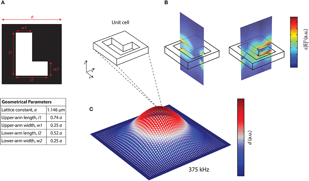
Figure 1. (A) Standard geometrical parameters for the L-shaped unit cell. (B) FEM simulated electrical energy density for a typical metasurface mode. For improved visibility cut planes xz and yz are shown. (C) Modulus of the total displacement of the FEM simulated fundamental mechanical mode.
The simulation of the low-frequency mechanical modes requires the geometry of the full suspended structure. Continuous mechanics FEM simulations have been used in order to find the resonant frequency of the first eigenmodes. GaAs has been parametrized using the elasticity matrix and material density [22], the former being properly rotated for our crystal orientation. An illustration of the fundamental drum mode is reported in Figure 1C; here the colormap indicates the modulus of the mechanical displacement, , with u, v, and w displacement components along x, y, and z directions, respectively, while the artificial displacement has been artificially exaggerated for visualization purposes. The mode resonant frequency has been found to be 372 kHz, in good agreement with independent characterization with a Laser Doppler Vibrometer [20].
The metasurface was fabricated starting with a GaAs wafer on which a 1.5 μm Al0.5GaAs0.5 sacrificial layer has been grown by Molecular Beam Epitaxy (MBE). On top of that, a further 220 nm GaAs (device) layer was further grown. An electron beam resist mask (AllResist AR-P6200) was spun on the sample and subsequently exposed using a 30 keV electronic beam. In particular, the single metasurface pattern has been replicated in such a way to cover roughly 50 × 50 μm areas (50 × 50 lattice constants) which also define the membrane size. Each area has been exposed using a different geometrical scaling factor (up to 10% modification) in order to slightly tune the photonic resonances. Among all the different fabricated metasurfaces we focused on six devices, L1–L6, which have been exposed considering the scaling factor reported in Table 1.
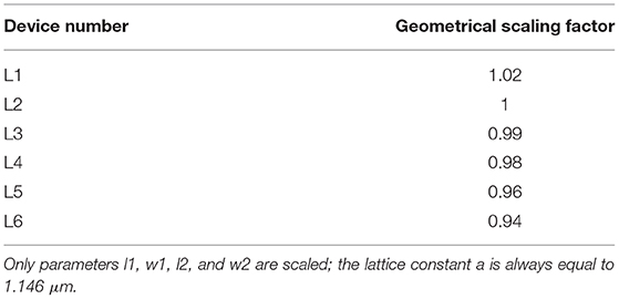
Table 1. Scaling of the geometrical parameters reported in Figure 1.
The exposed pattern has been transferred to GaAs using a Chlorine-based Inductively Coupled Plasma—Reactive Ion Etching (ICP-RIE, Sentech SI 500) machine; plasma has been ignited from a gas mixture of BCl3/Cl2/Ar, with 6/1/10 sccm, respectively. As a last step, the membranes were released in a pure HF solution. The fabricated devices have been preliminarily inspected with Scanning Electron Microscopy: a full schematic of the fabrication flow and a micrograph of a typical device are reported in Figure 2.
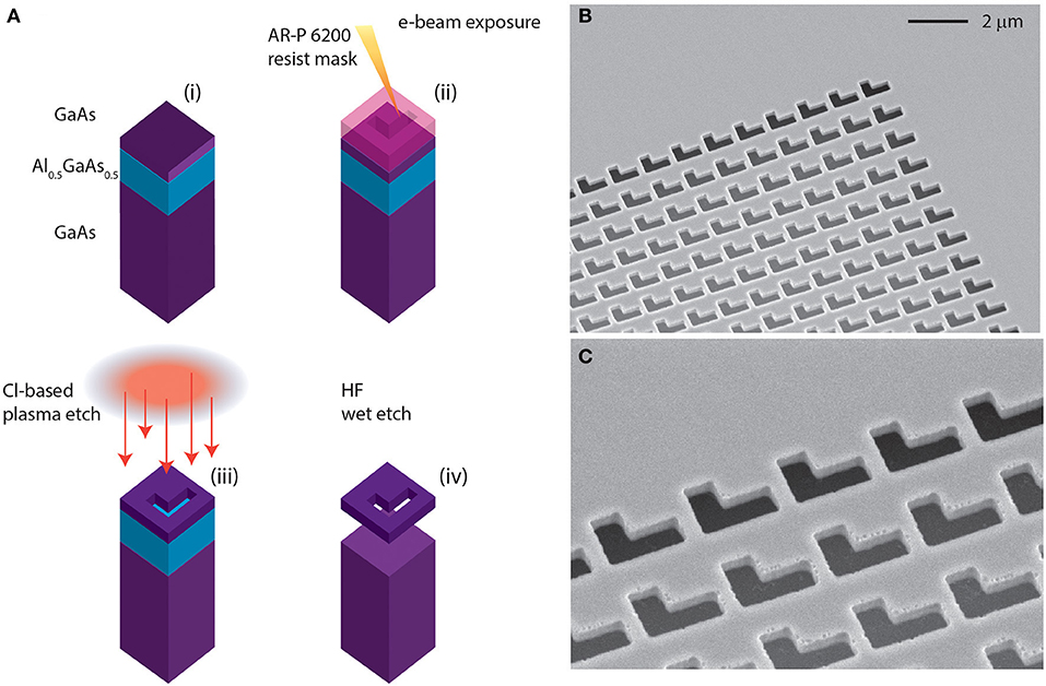
Figure 2. (A) Fabrication steps. Starting from a GaAs/Al0.5GaAs0.5 heterostructure (i), we spin-coat a layer of AR-P 6200 resist (ii). E-beam lithography is used to define the patterns, (iii) which are transferred on the device layer through a dry etching step (iv). Finally, the full structure gets released through HF wet etching. The SEM micrograph (B) shows a typical fabricated device with a magnification of the pattern (C).
Static Characterization
The metasurface was characterized by reflectance spectra. Light coming from a tunable near-infrared laser (Newport TLD600) was shined on the device using a lens with 7 cm focal length. This produced a roughly 50 μm wide beam spot on the device layer. All experiments were performed at normal incidence; after interacting with the metasurface, the reflected laser light was sent into a detection stage through a beam splitter. The output signal was then detected either using a commercial polarimeter (Thorlabs PAX-1000, maximum sampling rate 600 Hz) or using a fast InGaAs detector (Newport, 1623). In the latter case, it is possible to add a linear polarizer filter to partially inspect the polarization state of the reflected light. A sketch of the experimental setup is shown in Figure 3A. The piezoelectric actuator and the lock-in amplifier (LIA) are used for the dynamic characterization and are initially disconnected.
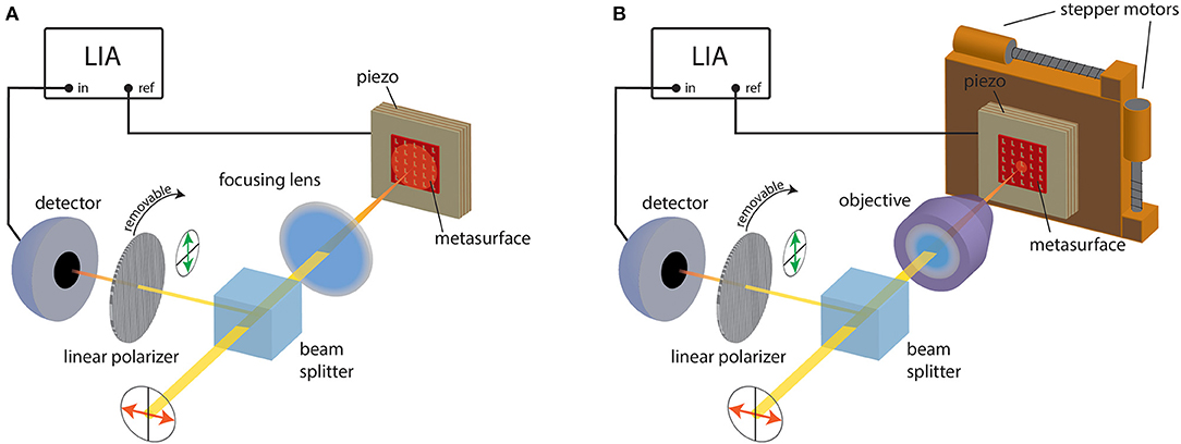
Figure 3. Experimental set configurations. (A) Sketch of the experimental setup. The laser light is focused on the metasurface; the reflected signal is then sent to an IR detector through a beam splitter. A linear polarizer filter can be inserted before detection. The signal is then analyzed with a lock-in amplifier (LIA) whose reference signal is used to control the piezoelectric driving stack. (B) Same as (A) with a microscope objective instead of the focusing lens and the metasurface additionally sitting on a motorized stage for spatial maps. Note that in the sketches the laser beam size is not in scale.
At first, we have characterized a full set of metasurfaces which have been fabricated in the same run with different geometrical scaling factors (L1–L6). Impinging laser light polarization was linear horizontal (x-direction), in a wavelength range from 1,520 to 1,570 nm; no analyzer was present in front of the fast detector. The reflectivity spectra of different membranes are reported in Figure 4A and mostly show fast signal oscillations which originate from multiple reflections from the substrate, both considering the first air-GaAs interface as well as the bottom GaAs-air interface. These oscillations are modulated by slowly-varying envelopes coming from the proper metasurface resonances. This can be better seen by inserting the linear polarizer in front of the detector and rotate it in such a way to project the polarization state along the vertical linear polarization state (y-direction). This makes the detection system sensitive to polarization rotation. In particular, the metasurface resonances emerge, being the only physical system in the experimental line capable of modifying the polarization state of light. The cross-polarization reflectivity results are reported in Figure 4B, where the signal envelopes now take the shape of Fano-shaped [23] broad peaks, directly coming from the metasurface resonance. As can be seen, the small change of the geometrical parameters gives a shift in the metasurface resonances. In particular, device L1 showed a localized, strong peak around 1,545 nm, making it the perfect candidate for a deeper photonic and mechanical characterization. To this end, we mounted the device in a slightly different setup, where the sample sits on a motorized stage and the laser light is focused through a 50×, long working distance objective (see Figure 3B). The stronger focusing effect results in an estimated beam size of about 5 μm on the sample surface enabling local probing of the membrane. Figure 5A reports a map of the cross-polarized reflectivity at 1,532.5 nm around L1 central position. A distinct region representing the metasurface is clearly visible, owing to the device polarization rotation characteristic, whereas the contribution coming from the substrate is negligible thanks to the polarization filter effect. The full cross-polarized spectra of few selected points on the map have also been reported in Figure 5: as can be seen, the spectra recorded in the central region of the membrane all share a qualitatively similar shape, with small differences due to some inhomogeneity present on the membrane; note that the spectrum is quite different from the one shown in Figure 4B, due to the different excitation condition in terms of accessible wavevectors. The spectra recorded in the outer region show a residual, small polarization rotation effect, likely given by a small overlap of the laser beam with the outermost metasurface pattern.
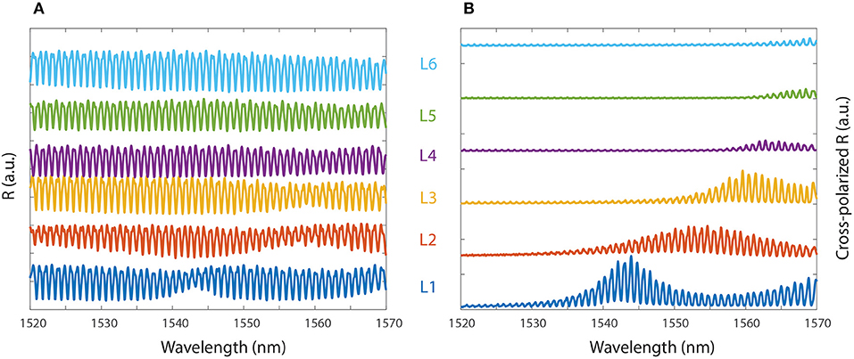
Figure 4. Direct (A) and Cross-polarized (B) reflectivity spectra for different metasurfaces.
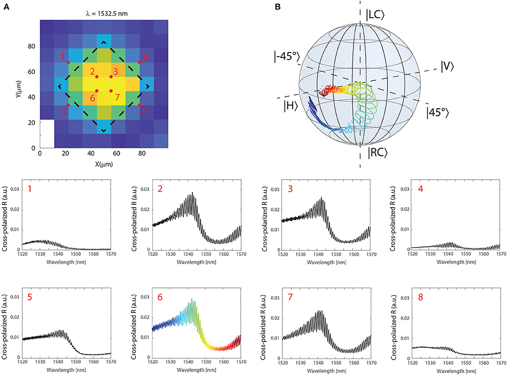
Figure 5. (A) Map of the cross-polarized signal at 1,532.5 nm across the membrane, whose contour is indicated as a guide for the eyes. The spectra in selected points (1–8) are individually reported. (B) Spectral evolution on the Poincaré sphere probing the point 6 of the membrane. The cross-polarized spectrum and the Poincaré plot are correlated through the plot color.
To gain a better insight on the polarization conversion effect, we focused the laser light on point six of the membrane, at the same time changing the fast detector with the polarimeter. In this way, it is possible to follow the spectral evolution of the polarization state on the Poincaré sphere [see for example [24]], which is the standard tool used to illustrate the Stokes parameters S1, S2, and S3 directly measured by the polarimeter [25]. The experimental results are shown in Figure 5B, where the colormap allows to associate points on the Poincaré sphere with the cross-polarized spectrum in panel number six. Far from the resonance, the polarization is almost equal to the input one (linear horizontal). By getting closer to the resonance, the polarization state is rotated becoming elliptical. Interestingly, it can be clearly seen that the state evolves in spiral loops, corresponding to the multiple Fabry-Perot resonances originated by the substrate. This is a clear indication that the overall phase shift given by the multiple reflection of light in the substrate strongly influences the metasurface operation and polarization conversion power. Within a single Fabry-Perot fringe, the phase of light undergoes a 2π shift. If the metasurface is influenced by the phase, one should expect a closed path on the Poincaré sphere when one single fringe is probed with the laser. The fact that the loops are not closed is due to the dispersion characteristic: in fact, a full phase round trip is concluded at a different wavelength than the one in the initial point of the sweep. Therefore, even if the same Fabry-Perot induced phase shift occurs, the different metasurface response at different wavelength results in a different conversion effect, clearly visible on the Poincaré sphere. This important observation points toward the strong possibility of changing the polarization conversion effect by simply acting on the phase of light reflected from the substrate; this can be easily done by changing the metasurface—substrate separation distance.
Coherent Dynamic Characterization
The effect of mechanical modes on the metasurface polarization conversion effect can be evaluated by placing the sample on a piezoelectric multilayer stack, driven by a high-frequency local oscillator. This can be taken as a reference for demodulating the fast detector signal with a lock-in amplifier (LIA) (Zurich Instruments, UHF-LI). The signal read by the LIA is a direct measurement of the effect of the mechanical force on the state of light: by inserting/removing the analyzer, we can infer the case of general intensity modulation with the more relevant polarization conversion. In fact, if the polarization is not modified, the reflectivity spectra with and without the analyzer will be linearly proportional, with a scaling factor coming from the projection of the output (constant) polarization state on the linear vertical state.
Initially, we used the objective setup (Figure 3B) to focus the laser in the center of the membrane. Setting a laser wavelength of 1,532.5 nm, corresponding to a local maximum in one of the fringes of Figure 4B, we swept the piezo drive frequency while at the same time recording the LIA amplitude signal, RLIA. The result reported in Figure 6A shows a rich spectrum, which originates from the convolution of the piezoelectric stack out-of-plane modes and the membrane fundamental drum mode. This mode is strongly overdamped at atmospheric pressure and can be excited over a wide frequency range around its central resonance at about 413 kHz. Setting this frequency as a monochromatic drive of the piezo actuator, we probed the spatial dependence of the mechanical-induced polarization conversion around the membrane central position. The resulting map, reported in Figure 6B, is in good agreement with the expected mechanical simulations shown in Figure 1C.
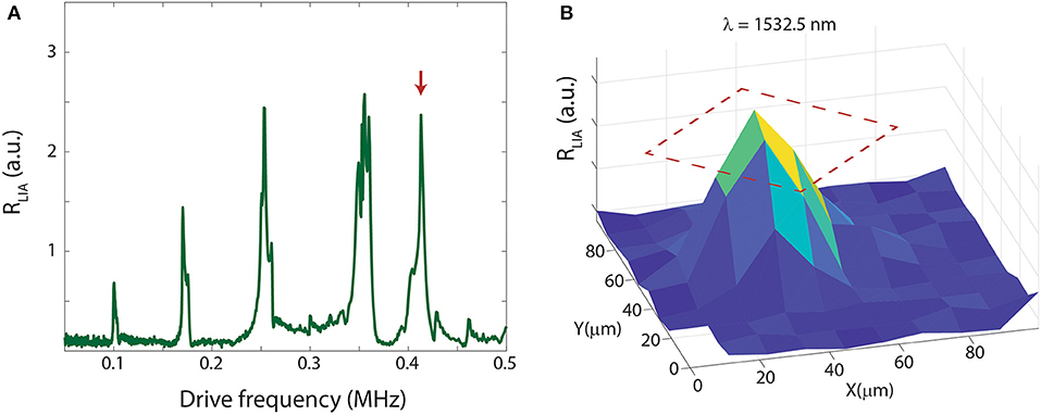
Figure 6. (A) Piezo-driven mechanical spectrum at atmospheric pressure with the laser focused in the membrane center. The peaks identify the out-of-plane mechanical eigenmodes of the piezo stack. (B) Map of the LIA amplitude at 430 kHz [red arrow in (A)] around the membrane position. The full metasurface position is overlaid with a red-dashed line as a guide for the eyes.
Switching from the objective to the focusing lens, in order to avoid any effect due to possible local inhomogeneity of the sample, we scan a laser while keeping the piezo drive at 413 kHz with a constant amplitude of 100 mV. At first, we analyzed the direct mechanical-induced light intensity modulation; the measured RLIA is reported as a blue trace in one of the inset of Figure 7 (second column, third row, bold box), showing a non-negligible modulation effect even at wavelength far from the metasurface resonance, probably due to small changes in reflectivity of the whole chip with respect to its static configuration. On the other hand, upon the insertion of the analyzer, the spectral shape of the signal is strongly modified, suggesting that an intensity modulation can be accompanied by a pure polarization conversion effect (see Figure 7, same panel, red trace). Note that the slight mismatch of the signal fringes can be imputed by the different polarization components detected in the experiment. The largest conversion effect is found around the maximum of the cross-polarized signal reported in Figure 4. A quantitative calibration of the conversion effect, which is dynamically following non-trivial paths on the Poincaré sphere, can be obtained after a careful calibration of the system, which is out of the scope of this paper and can be found elsewhere [20].
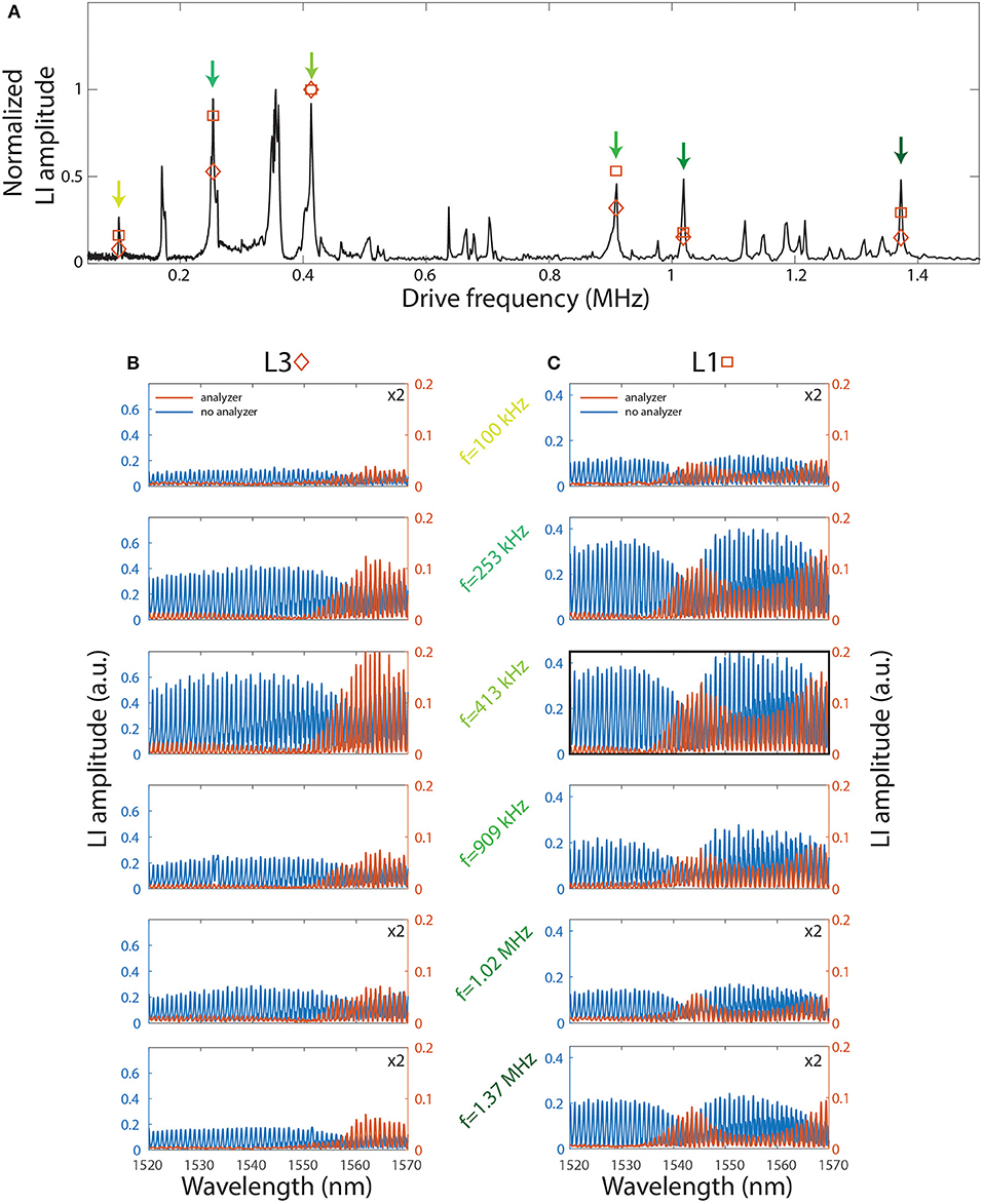
Figure 7. (A) Broadband mechanical spectrum. LIA-demodulated spectra for several driving frequencies are reported for sample L3 (B) and L1 (C).
The overdamped drum mode we are considering allows one to work at several different mechanical frequencies, mainly limited by the range of operation of the driving stack. To show that, we recorded a broad band mechanical spectrum, reported in Figure 7A, where narrow and strong peaks can be seen up almost 1.5 MHz. We selected several driving peaks for testing the metasurface polarization conversion effect, in a range from 100 kHz to ~1.4 MHz (colored arrows in Figure 7). The results for devices L1 and L3 are reported in Figures 7B,C, respectively. First observation is that the spectral shapes of the signals RLIA with (red curve) and without (blue curve) the polarization analyzer are significantly different at all the measured mechanical frequencies. Furthermore, for each spectrum, we can take the maximum of cross polarized RLIA, which is the LIA amplitude signal when the analyzer is present. The results are superimposed in the broad mechanical spectrum of Figure 7A, showing a good correlation between mechanical mode amplitude and polarization conversion effect. This results shows that the main operation limitation in terms of bandwidth arises from the engineering of a proper excitation spectrum of the piezoelectric stack. Changing the drive would allow for operating at any desired conversion frequency at least in the range we tested from 100 kHz to ~1.4 MHz, giving the advantage of a non-resonant excitation bandwidth with the extremely low power consumption, which in similar devices has produced polarization rotations of roughly 0.07 rad/mV [19].
Conclusions
In conclusion we have shown a broad band (0–1.4 MHz) polarization conversion effect of near-infrared light using the coherent mechanical motion of an optomechanical metasurface. The all- dielectric, low-loss metasurfaces, potentially integrable at chip level, operates in free-space, and represents a key technology for full control of light parameters (amplitude, phase, and polarization) with the potential for ultra-high frequency operation when high order mechanical modes are excited.
Data Availability Statement
The datasets generated for this study are available on request to the corresponding author.
Author Contributions
The device was conceived jointly by SZ, AT, and AP. SZ designed the structure and fabricated the sample starting from a heterostructure grown by GB. MC and AP performed the experiments. All authors participated in the discussion of the results. AP wrote the manuscript with contribution from all the other authors.
Funding
Funding from FET-Open project PHENOMEN (GA 713450) was gratefully acknowledged. ICN2 was supported by the Severo Ochoa program from the Spanish MINECO (Grant No. SEV-2017-0706) and funding from the CERCA Programme/Generalitat de Catalunya.
Conflict of Interest
The authors declare that the research was conducted in the absence of any commercial or financial relationships that could be construed as a potential conflict of interest.
Acknowledgments
DN-U gratefully acknowledge the support of a Ramón y Cajal postdoctoral fellowship (RYC-2014-15392).
Footnotes
1. ^Available online at: https://it.mathworks.com/matlabcentral/fileexchange/55401-ppml-periodically-patterned-multi-layer
References
1. Liu S, Vabishchevich PP, Vaskin A, Reno JL, Keeler GA, Sinclair MB, et al. An all-dielectric metasurface as a broadband optical frequency mixer. Nat Commun. (2018) 9:1–6. doi: 10.1038/s41467-018-04944-9
2. Arbabi A, Horie Y, Bagheri M, Faraon A. Dielectric metasurfaces for complete control of phase and polarization with subwavelength spatial resolution and high transmission. Nat Nanotech. (2015) 10:937. doi: 10.1038/nnano.2015.186
3. Jahani S, Jacob Z. All-dielectric metamaterials. Nat Nanotechnol. (2016) 11:23. doi: 10.1038/nnano.2015.304
4. Jiang J, Fan JA. Global optimization of dielectric metasurfaces using a physics-driven neural network. Nano Lett. (2019) 19:5366. doi: 10.1021/acs.nanolett.9b01857
5. Molesky S, Lin Z, Piggott AY, Jin W, Vucković J, Rodriguez AW. Inverse design in nanophotonics. Nat Phot. (2018) 12:659. doi: 10.1038/s41566-018-0246-9
6. Lee G-Y, Hong J-Y, Hwang SH, Moon S, Kang H, Jeon S, et al. Metasurface eyepiece for augmented reality. Nat Commun. (2018) 9:4562. doi: 10.1038/s41467-018-07011-5
7. Capasso F. The future and promise of flat optics: a personal perspective. Nanophotonics. (2018) 7:953. doi: 10.1515/nanoph-2018-0004
8. Ou J-Y, Plum E, Zhang J, Zheludev NI. An electromechanically reconfigurable plasmonic metamaterial operating in the near-infrared. Nat Nanotechnol. (2013) 8:252. doi: 10.1038/nnano.2013.25
9. Zheludev NI, Plum E. Reconfigurable nanomechanical photonic metamaterials. Nat Nanotechnol. (2016) 11:16. doi: 10.1038/nnano.2015.302
10. Ee H-S, Agarwal R. Tunable metasurface and flat optical zoom lens on a stretchable substrate. Nano Lett. (2016) 6: 2818–23. doi: 10.1021/acs.nanolett.6b00618
11. Liu M, Powell DA, Guo R, Shadrivov IV, Kivshar YS. Polarization-induced chirality in metamaterials via optomechanical interaction. Adv Opt Mater. (2017) 5:1600760. doi: 10.1002/adom.201600760
12. Ji R, Hua Y, Chen K, Long K, Fu Y, Zhang X, et al. A switchable metalens based on active tri-layer metasurface. Plasmonics. (2019) 14:165. doi: 10.1007/s11468-018-0789-0
13. Rahmani M, Xu L, Miroshnichenko AE, Komar A, Camacho-Morales R, et al. Reversible thermal tuning of all-dielectric metasurfaces. Adv Funct Mater. (2017) 27:1700580. doi: 10.1002/adfm.201700580
14. Iyer PP, DeCrescent RA, Lewi T, Antonellis N, Schuller JA. Uniform thermos-optic tunability of dielectric metalenses. Phys Rev Appl. (2018) 10:044029. doi: 10.1103/PhysRevApplied.10.044029
15. Yang C, Wang Z, Yuan H, Li K, Zheng X, Mu W, et al. All-dielectric metasurface for highly tunable, narrowband notch filtering. IEEE Photonics J. (2019) 11:4501006. doi: 10.1109/JPHOT.2019.2931702
16. Kamali KZ, Xu L, Ward J, Wang K, Li G, Miroshnichenko AE, et al. Reversible image contrast manipulation with thermally tunable dielectric metasurfaces. Small. (2019) 15:1805142. doi: 10.1002/smll.201805142
17. Bosch M, Shcheerbakov MR, Fan Z, Shvets G. Polarization states synthesizer based on a thermo-optic dielectric metasurface. J Appl Phys. (2019) 126:073102. doi: 10.1063/1.5094158
18. Aspelmeyer M, Kippenberg TJ, Marquardt F. Cavity optomechanics. Rev Mod Phys. (2014) 86:1391. doi: 10.1103/RevModPhys.86.1391
19. Midolo L, Schliesser A, Fiore A. Nano-opto-electro-mechanical systems. Nat Nanotech. (2018) 13:11. doi: 10.1038/s41565-017-0039-1
20. Zanotto S, Tredicucci A, Navarro-Urrios D, Cecchini M, Biasiol G, Mencarelli D, et al. Optomechanics of chiral dielectric metasurfaces. Adv Opt Mater. (2019). doi: 10.201810.1002/adom.201901507. [Epub ahead of print].
21. Zanotto S, Mazzamuto G, Riboli F, Biasiol G, La Rocca GC, Tredicucci A, et al. Photonic bands, superchirality, and inverse design of a chiral minimal metasurface. Nanophotonics. (2019) 8:2291. doi: 10.1515/nanoph-2019-0321
22. Adachi S. GaAs, AlAs, and AlxGa1–xAs: material parameters for use in research and device applications. J Appl Phys. (1985) 58:R1. doi: 10.1063/1.336070
23. Collin S. Nanostructure arrays in free-space: optical properties and applications. Rep Prog Phys. (2014) 77:126402. doi: 10.1088/0034-4885/77/12/126402
Keywords: metasurface, optomechanics, polarization, chirality, nanomechanics
Citation: Zanotto S, Colombano M, Navarro-Urrios D, Biasiol G, Sotomayor-Torres CM, Tredicucci A and Pitanti A (2020) Broadband Dynamic Polarization Conversion in Optomechanical Metasurfaces. Front. Phys. 7:231. doi: 10.3389/fphy.2019.00231
Received: 31 October 2019; Accepted: 10 December 2019;
Published: 10 January 2020.
Edited by:
Lorenzo Pavesi, University of Trento, ItalyReviewed by:
Andrey Miroshnichenko, University of New South Wales, AustraliaVenu Gopal Achanta, Tata Institute of Fundamental Research, India
Copyright © 2020 Zanotto, Colombano, Navarro-Urrios, Biasiol, Sotomayor-Torres, Tredicucci and Pitanti. This is an open-access article distributed under the terms of the Creative Commons Attribution License (CC BY). The use, distribution or reproduction in other forums is permitted, provided the original author(s) and the copyright owner(s) are credited and that the original publication in this journal is cited, in accordance with accepted academic practice. No use, distribution or reproduction is permitted which does not comply with these terms.
*Correspondence: Alessandro Pitanti, alessandro.pitanti@nano.cnr.it