Phase-Field Model of Hydride Blister Growth Kinetics on Zirconium Surface
 Shuai Wu
 Jie Sheng3
  Houbing Huang
 Yu Liu
 Haifeng Song
- 1School of Materials Science and Engineering, Beijing Institute of Technology, Beijing, China
- 2Advanced Research Institute of Multidisciplinary Science, Beijing Institute of Technology, Beijing, China
- 3Laboratory of Computational Physics, Institute of Applied Physics and Computational Mathematics, Beijing, China
The precipitation of zirconium hydride blisters on the surface of zirconium alloy cladding destroys the integrity of the material and leads to material failure, which has serious potential safety hazards. To study the corrosion kinetics of zirconium hydride blisters, we established a phase-field model coupled with anisotropic elastic, which can reflect the microstructure evolution process of zirconium hydride blisters. The model studies the natural growth of hydride blister and the structural evolution process after applying radial stress and discusses the corrosion characteristics, stress distribution, and displacement changes. Zirconium hydride blisters tend to be semi-ellipsoidal in natural growth. Applying radial outward stress will promote the growth of blisters and aggravate the harm of corrosion. The stress state changes with applying stress, which affects the elastic driving force, resulting in the change of blister morphology. This work is helpful to understand the corrosion kinetic mechanism of hydride blisters.
Introduction
Zirconium alloy has a low neutron absorption rate and good high-temperature corrosion resistance and is widely used in structural materials in fuel cladding of water-cooled reactors (Krishnan and Asundi, 1981; Bair et al., 2015; Motta et al., 2015). However, severe waterside corrosion reactions occur during use and storage, and its performance will also be limited (Hong et al., 2002; Han et al., 2019). During the corrosion process on the waterside, the outer layer of the zirconium alloy cladding is oxidized, releasing hydrogen atoms, and the hydrogen atoms migrate into the zirconium matrix. It moves along the hydrostatic stress gradient and moves against the thermal gradient (Kammenzind and Berquist, 2000; Reheman and Ståhle, 2018). In other words, hydrogen is attracted to high-stress areas and cold areas, or areas where the two interact together. When the hydrogen concentration exceeds the solid solution limit in the zirconium matrix, zirconium and solid solute hydrogen transform into the zirconium hydride phase (Ghosal et al., 2002; Bair et al., 2015; Reheman and Ståhle, 2018; Han et al., 2019). The formation of brittle hydride will not only cause the material to expand and increase its volume greatly, but also it is easy to initiate crack growth and penetrate the matrix (Kim et al., 2007; Puls, 2009; McRae et al., 2010). The hydride formed on the metal surface appears as a small bump, usually called a blister (Cheong et al., 2001; Singh et al., 2002). The growth of zirconium hydride blister is an important form of pitting corrosion. It is the main initiation point of fuel cladding failure in nuclear power plants, which will pose a serious threat to nuclear power safety. Therefore, the basic understanding of hydride blister growth behavior is of great significance for predicting material performance degradation and failure.
The size of the hydride blister is much larger than that of the single hydride, reaching the micrometer level (Cheong et al., 2001; Singh et al., 2002; Long et al., 2017; Kim et al., 2018). The formation of the hydride blister requires the existence of a cold spot in the surrounding environment, and the effect of cold spot aggregation on the growth of hydride blisters is also different (Singh et al., 2002). In the experiment of (Domizzi et al., 1996), the growth of blisters on the surface of the Zr-2.5% Nb alloy tube was studied. It divides the observed phenomenon into three areas (I) the main part of the zirconium hydride blister, whose growth is similar to that of a single hydride, and the anisotropic growth is ellipsoidal, (II) the radial hydride accumulation area, and (III) circumferential hydride accumulation area. The phase-field method has been widely used to study the microstructure changes such as hydride precipitation in Zr cladding materials (Bair et al., 2015; Bair et al., 2016; Bair and Zaeem, 2017; Bair et al., 2017; Han et al., 2019; Toghraee et al., 2021). Based on region (I) (Reheman and Ståhle, 2018), studies the growth and cracking of hydride blisters under elastic-plastic action by using the phase-field method, but its model is established based on isotropy, which can not represent the anisotropic growth of zirconium hydride blisters. In this work, we study the morphological evolution of zirconium hydride blisters by using the phase-field method coupled with anisotropic elastic strain energy. In addition, some studies (Cheong et al., 2001; Motta and Chen, 2012) show that during reactor operation, the fission gas and the helium filling gas in the cladding tube create a combined pressure that exposes the nuclear fuel cladding to constant stress. Even the swelling of nuclear fuel also produces a certain pressure on the zirconium alloy cladding tube (Rozhnov et al., 2011). Therefore, it is important to understand the evolution mechanism of zirconium hydride blisters under specific pressure. The evolution of hydride blisters under radial stress is considered in this work.
Phase-Field Model
Combining the zirconium hydrogen phase diagram (Yu et al., 2020) and experimental research (Santisteban and Domizzi, 2009; Vicente Alvarez et al., 2011; Lin et al., 2016; Motta et al., 2019), it can be found that the hydrides in the zirconium hydride blister are all δ-hydrides, and the ratio varies approximately in the range of 60–85%, and the rest is the Zr matrix and impurities. Since the chemical energy parameters of the zirconium hydride blister are not clear yet, we simulate the zirconium hydride blister by using the chemical energy (Bair et al., 2016; Bair and Zaeem, 2017; Bair et al., 2017; Toghraee et al., 2021) and elastic parameters (Bair et al., 2017; Han et al., 2019) of the δ-hydride. The size of the cladding tube in the model is similar to some studies (Hong et al., 2002; Hellouin de Menibus et al., 2014), and 11.25-degree section is simulated. Since the longitudinal plane of the blister is usually observed in the experiment, we convert the data in the z-y direction of the coordinate axis to x-y. The whole calculation process is carried out in two dimensions. Figure 1 shows the setting of the hydride blister growth model and boundary conditions. For the displacement field
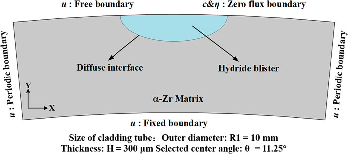
FIGURE 1. Schematic diagram of zirconium-zirconium hydride blister model and boundary condition settings.
Governing Equations and Bulk Free Energy
Interfacial reaction, hydrogen transport driven by diffusion potential, and internal stress caused by precipitation and growth of zirconium hydride blister. Multi-physical field coupling based on dynamic equations can simulate these effects and reflect the dynamic characteristics (Shi et al., 2021; Liu et al., 2022; Shi et al., 2022). The phase field, hydrogen concentration field, and elastic strain energy field were coupled to establish the zirconium hydride blister growth model in this study. These fields are necessary to track the movement of the diffusion interface, calculate the diffusion/redistribution of hydrogen (Yang et al., 2021), and reveal the effect of radial stress on hydride growth. The advantage of the phase-field model in this study is that the shape of the grown precipitates can be calculated (Gao et al., 2021; Gao et al., 2022; Xu et al., 2022). The phase transition from metal to hydride is given by a phase variable η that continuously covers a range of values, where the ends of the range represent pure metal or pure hydride, respectively. The analysis is based on totally free energy, including strain energy, chemical potential energy, and gradient energy describing the diffusion interface. In the phase-field model, both the diffusion of hydrogen atoms and the precipitation of hydrides are considered. The time evolution of the concentration c is determined by the Cahn-Hilliard diffusion equation (Kim et al., 2008), and the evolution of the microstructural parameter η is governed by the time-dependent Allen-Cahn equation (Allen and Cahn, 1979). In order to solve the evolution equation, the finite element method is adopted, and the mesh adaptive method is used to speed up the calculation.
The driving force of the zirconium-hydride blister phase-field model comes from the minimization of the total free energy (
Here, all the parameters used in this simulation are listed in Table. 1 The bulk chemical free energy
TABLE 1. Model parameters and conditions used in the simulations.
The Kim-Kim-Suzuki (KKS) binary alloy model (Kim et al., 1999) is used to determine the expression form of bulk chemical free energy density. The KKS model assumes that each material point is considered to be a mixture of two or more phases with different concentrations, and the diffusion potentials of the same concentration between different phases are equal. The assumption can be expressed as follows:
where
Two-phase molar free energy
Here,
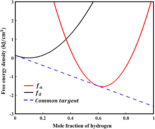
FIGURE 2. Two-phase chemical free energy density curves of zirconium matrix and zirconium hydride blister.
The interfacial energy density can generally be written as a function of the gradient of the phase-field variable,
where
Elastic Strain Energy and Applied Stress
When hydride blister precipitate and grow in the matrix, their elastic strain energy comes from the structural difference between hydride blister and matrix. The elastic strain energy
where
The elastic strain
where
Results and Discussion
The effect of anisotropic elastic energy on the growth morphology of hydride blisters is explored, as shown in Figures 3A,C, which are the evolution results of hydride blisters after initial state t = 0 s and final state t = 1500 s, respectively. Due to the effect of elastic energy, the corrosion width of hydride blister is greater than the corrosion depth, the growth characteristics of anisotropy appear, and the morphology is semi ellipsoid. In addition, there is a slight bulge at the top of the blister. The growth of the hydride blister is closely related to the intrinsic strain, and to minimize the elastic properties, different growth rates will appear in different directions. Figures 3B,D show that the concentration in the hydride blister is relatively high, and there is a diffusion area at the interface between the matrix and the hydride blister. Figures 3E,F are the stress distribution results in the radial and circumferential directions of the coupled anisotropic elastic energy, respectively. The hydride blisters in both directions are in a compressed state, and there are stress concentration area near the phase interface and the tips on both sides. The stress concentration will redirect the δ-hydrides around the hydride blisters, form more harmful radial hydride clusters, and even cause the initiation and propagation of microcracks.
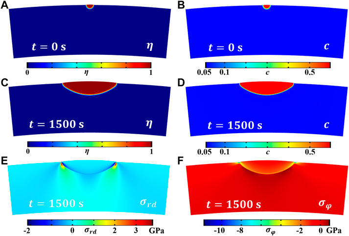
FIGURE 3. The evolution results of the coupled anisotropic elastic energy zirconium hydride blister, where (A) and (C) are the morphology evolution results (order parameter field) of the hydride blister growth at t = 0 s and t = 1,500 s, (B), and (D) is the distribution of hydrogen concentration field after t = 0 s and t = 1,500 s, (E) and (F) are the stress distribution of
Zirconium alloy cladding tube will be subjected to a certain radial outward stress during operation, which will have a great impact on the formation and growth of hydride. We applied stress of 1, 2, and 3 GPa along the radial direction in this model. Because this model is established under the ideal condition of no defects, the applied stress is much greater than that of the actual cladding tube. We can qualitatively study the effect of radial stress on the growth morphology of hydride blisters. The evolution results after t = 1,500 s are shown in Figure 4. Figures 4A–C shows that the width and depth of hydride blister increase with the increase of stress under the application of different radial stress. Figure 4D shows the contour comparison diagram of hydride blister under t = 1,500 s applied stress and no applied stress. The results in Figure 4 confirm that applying radial stress will change the morphology and dynamic evolution of blisters, promote the growth of blisters and enhance the process of pitting corrosion.
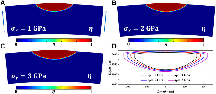
FIGURE 4. At t = 1,500 s, (A–C) are the growth morphologies of hydride blisters under 1, 2, 3 GPa radial stress, respectively (The direction of stress application is indicated by blue arrows). (D) is the contours of hydride blisters.
Figure 5A shows the change of corrosion depth of the hydride blister with time. It can be seen intuitively that the growth of hydrogenated blister is affected by different radial stresses, and the corrosion depth of hydride blister will increase with the increase of time and radial outward stress. Figure 5B shows the changes of the area of hydride blister and the average corrosion rate along the pitting depth under different radial stresses. It can be found that the greater the applied radial stress is, the more the corrosion area will be increased, which also shows that the radial stress will increase the influence of pitting corrosion. The corrosion rate changed from fast to slow, which may be due to the continuous consumption of hydrogen in the surrounding environment during the evolution process. The reduction of hydrogen content has become one of the key factors restricting its growth. After the stress is applied, the initial growth speed becomes larger, and the larger the value is, the more obvious the speed increase is, and then it will tend to be consistent. The matrix has a compressive effect on the expansion and growth of hydride blisters. The expansion state of the hydride blister in the simulation area is realized by the bending of the grid (Sheng et al., 2022). After the external stress is applied, the external stress will affect the overall stress state of the blister, and then affect its growth morphology. The growth of hydride bubbles is controlled by these three effects. Figure 5C,D show the distribution of displacement
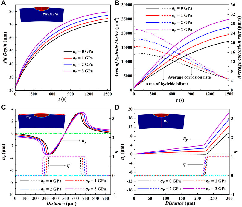
FIGURE 5. (A) The corrosion pit depth, (B) the average corrosion rate and the area of hydride blister as a function of time under different radial stresses. Variation of (C) displacement component
As mentioned above, applying different of radial outward stress to the whole simulation area will have a great impact on the growth of the hydride blister. Figure 6A and Figure 6B are t = 1,500 s respectively, under the application of 2 GPa radial stress
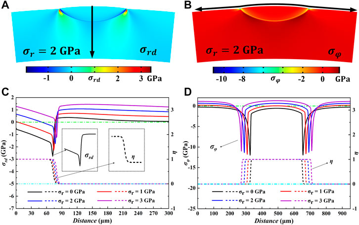
FIGURE 6. The distribution of (A)
Conclusion
In this work, the anisotropic elastic properties are introduced into Zr-Hydride blister system, and the growth and evolution dynamics of zirconium hydride blister are studied by using phase-field model. The simulation results show that the natural growth morphology of hydride blister tends to be semi-ellipsoidal and in a compressed state, while the matrix near the interface is in a tensile state. There is a stress concentration area on the outer contour of the blister, and the maximum value appears at the end points on both sides of the hydride. The external stress affects the growth morphology of zirconium hydride blister by affecting the elastic stress distribution. Applying radial outward stress will promote the growth of blister, and its corrosion width and depth will increase. The greater the applied stress, the more obvious the promotion effect and the faster the growth rate. This model also has certain application value in other fields of pitting corrosion.
Data Availability Statement
The original contributions presented in the study are included in the article/Supplementary Material, further inquiries can be directed to the corresponding authors.
Author Contributions
HH and YL conceived and guided the work. SW conducted simulation and data integration. The results were analyzed and discussed by all authors. JS gave guidance in the theoretical part. SW, JS, HH and YL jointly wrote the manuscript, with contributions from all the authors.
Funding
This work was supported by the Science Challenge Project (Grant No. TZZT2019-D1-03) and the Foundation of LCP.
Conflict of Interest
The authors declare that the research was conducted in the absence of any commercial or financial relationships that could be construed as a potential conflict of interest.
Acknowledgments
Authors would like to thank Changqing Guo, Yuechao Wang and Guomin Han for their help on the model and basic knowledge in this work.
Publisher’s Note
All claims expressed in this article are solely those of the authors and do not necessarily represent those of their affiliated organizations, or those of the publisher, the editors, and the reviewers. Any product that may be evaluated in this article, or claim that may be made by its manufacturer, is not guaranteed or endorsed by the publisher.
References
Allen, S. M., and Cahn, J. W. (1979). A Microscopic Theory for Antiphase Boundary Motion and its Application to Antiphase Domain Coarsening. Acta Metall. 27 (6), 1085–1095. doi:10.1016/0001-6160(79)90196-2
Bair, J., and Zaeem, M. A. (2017). Effects of Applied Strain on Formation, Shape Evolution, and Reorientation of Multiphase Zirconium Hydrides: A Multiphase Field Modeling Study. arXiv e-prints. 2017. doi:10.1016/j.commatsci.2021.110367
Bair, J., Zaeem, M. A., and Tonks, M. (2016). A Phase-Field Model to Study the Effects of Temperature Change on Shape Evolution Ofγ-Hydrides in Zirconium. J. Phys. D Appl. Phys. 49 (40). 405302. doi:10.1088/0022-3727/49/40/405302
Bair, J., Asle Zaeem, M., and Schwen, D. (2017). Formation Path of δ Hydrides in Zirconium by Multiphase Field Modeling. Acta Mater. 123, 235–244. doi:10.1016/j.actamat.2016.10.056
Bair, J., Asle Zaeem, M., and Tonks, M. (2015). A Review on Hydride Precipitation in Zirconium Alloys. J. Nucl. Mater. 466, 12–20. doi:10.1016/j.jnucmat.2015.07.014
Cheong, Y. M., Gong, U. S., and Chooea, K. N. (2001). Formation and Growth of Hydride Blisters in Zr-2.5Nb Pressure Tubes. Nucl. Eng. Technol. 33 (2), 192–200.
Domizzi, G., Enrique, R. A., Ovejero-García, J., and Buscaglia, G. C. (1996). Blister Growth in Zirconium Alloys: Experimentation and Modeling. J. Nucl. Mater. 229, 36–47. doi:10.1016/0022-3115(95)00204-9
Gao, R., Shi, X., Wang, J., and Huang, H. (2022). Understanding Electrocaloric Cooling of Ferroelectrics Guided by Phase‐field Modeling. Journal of the American Ceramic Society. 105 (6). 3689–3714. doi:10.1111/jace.18370
Gao, R., Shi, X., Wang, J., Zhang, G., and Huang, H. (2021). Designed Giant Room‐Temperature Electrocaloric Effects in Metal‐Free Organic Perovskite [MDABCO](NH4)I3 by Phase-Field Simulations. Adv. Funct. Mat. 31 (38), 2104393. doi:10.1002/adfm.202104393
Ghosal, S. K., Palit, G. C., and De, P. K. (2002). Corrosion of Zirconium Alloys in Nuclear Applications – A Review. Mineral Process. Extr. Metallurgy Rev. 22 (4-6), 519–546. doi:10.1080/08827500208547428
Han, G. M., Zhao, Y. F., Zhou, C. B., Lin, D.-Y., Zhu, X. Y., Zhang, J., et al. (2019). Phase-Field Modeling of Stacking Structure Formation and Transition of δ-hydride Precipitates in Zirconium. Acta Mater. 165, 528–546. doi:10.1016/j.actamat.2018.12.009
Hellouin de Menibus, A., Auzoux, Q., Dieye, O., Berger, P., Bosonnet, S., Foy, E., et al. (2014). Formation and Characterization of Hydride Blisters in Zircaloy-4 Cladding Tubes. J. Nucl. Mater. 449 (1-3), 132–147. doi:10.1016/j.jnucmat.2014.03.006
Hong, S. I., Lee, K. W., and Kim, K. T. (2002). Effect of the Circumferential Hydrides on the Deformation and Fracture of Zircaloy Cladding Tubes. J. Nucl. Mater. 303 (2-3), 169–176. doi:10.1016/s0022-3115(02)00814-0
Kammenzind, B. F., Berquist, B. M., Bajaj, R., Kreyns, P. H., and Franklin, D. G., R. B. (2000). The Long-Range Migration of Hydrogen through Zircaloy in Response to Tensile and Compressive Stress Gradients. Zirconium Nucl. Industry Twelfth Int. Symposium, 196–233. doi:10.1520/stp14301s
Kim, H.-J., Han, J.-H., Kaiser, R., Oh, K. H., and Vlassak, J. J. (2008). High-throughput Analysis of Thin-Film Stresses Using Arrays of Micromachined Cantilever Beams. Rev. Sci. Instrum. 79 (4), 045112. doi:10.1063/1.2912826
Kim, S.-D., Kim, J.-S., and Yoon, J. (2018). Phase Analysis of Hydride Blister in Zirconium Alloy. J. Alloys Compd. 735, 2007–2011. doi:10.1016/j.jallcom.2017.11.359
Kim, S. G., Kim, W. T., and Suzuki, T. (1999). Phase-field Model for Binary Alloys. Phys. Rev. E 60 (6), 7186–7197. doi:10.1103/physreve.60.7186
Kim, Y. S., Ahn, S. B., and Cheong, Y. M. (2007). Precipitation of Crack Tip Hydrides in Zirconium Alloys. J. Alloys Compd. 429 (1-2), 221–226. doi:10.1016/j.jallcom.2006.09.034
Krishnan, R., and Asundi, M. K. (1981). Zirconium Alloys in Nuclear Technology. Proc. Indian Acad. Sci. Engg. Sci.) 4 (1), 41–56. doi:10.1007/bf02843474
Lin, J.-l., Han, X., Heuser, B. J., and Almer, J. D. (2016). Study of the Mechanical Behavior of the Hydride Blister/rim Structure in Zircaloy-4 Using In-Situ Synchrotron X-Ray Diffraction. J. Nucl. Mater. 471, 299–307. doi:10.1016/j.jnucmat.2015.12.048
Liu, D., Wang, J., Jafri, H. M., Wang, X., Shi, X., Liang, D., et al. (2022). Phase-field Simulations of Vortex Chirality Manipulation in Ferroelectric Thin Films. npj Quantum Materials 7, 1–8. doi:10.1038/s41535-022-00444-8
Long, F., Kerr, D., Domizzi, G., Wang, Q., and Daymond, M. R. (2017). Microstructure Characterization of a Hydride Blister in Zircaloy-4 by EBSD and TEM. Acta Mater. 129, 450–461. doi:10.1016/j.actamat.2017.03.016
McRae, G. A., Coleman, C. E., and Leitch, B. W. (2010). The First Step for Delayed Hydride Cracking in Zirconium Alloys. J. Nucl. Mater. 396 (1), 130–143. doi:10.1016/j.jnucmat.2009.08.019
Motta, A. T., Capolungo, L., Chen, L.-Q., Cinbiz, M. N., Daymond, M. R., Koss, D. A., et al. (2019). Hydrogen in Zirconium Alloys: A Review. J. Nucl. Mater. 518, 440–460. doi:10.1016/j.jnucmat.2019.02.042
Motta, A. T., and Chen, L.-Q. (2012). Hydride Formation in Zirconium Alloys. Jom 64 (12), 1403–1408. doi:10.1007/s11837-012-0479-x
Motta, A. T., Couet, A., and Comstock, R. J. (2015). Corrosion of Zirconium Alloys Used for Nuclear Fuel Cladding. Annu. Rev. Mat. Res. 45 (1), 311–343. doi:10.1146/annurev-matsci-070214-020951
Puls, M. P. (2009). Review of the Thermodynamic Basis for Models of Delayed Hydride Cracking Rate in Zirconium Alloys. J. Nucl. Mater. 393 (2), 350–367. doi:10.1016/j.jnucmat.2009.06.022
Reheman, W., and Ståhle, P. (2018). Self-inflicted Fracture of Expanding Surface Precipitates. Fatigue Fract. Eng. Mater Struct. 41 (12), 2614–2628. doi:10.1111/ffe.12872
Rozhnov, A. B., Belov, V. A., Nikulin, S. A., and Khanzhin, V. G. (2011). Stress Corrosion Cracking of Zirconium Cladding Tubes: I. Proximate Local SCC Testing Method. Russ. Metall. 2010 (10), 979–983. doi:10.1134/s0036029510100186
Santisteban, J. R. S. A., and Domizzi, G. (2009). Determination of Residual Stresses Around Blisters in Zr-2.5% Nb Pressure Tubes. Powder Diffr. 24 (S1), S72–S76. doi:10.1154/1.3139056
Sheng, J., Wang, Y. C., Liu, Y., Wu, S., Xu, K., Chen, Z. H., et al. (2022). A Phase-Field Model for Simulating Hydrogen-Induced Pitting Corrosion with Solid-Solid Phase Transformation in the Metal. doi:10.48550/arXiv.2203.07289
Shi, X., Wang, J., Cheng, X., and Huang, H. (2021). Ultrafast Ferroelectric Domain Switching Induced by Nano‐Second Strain‐Pulse, Advanced Theory and Simulations. 5 (3). 2100345. doi:10.1002/adts.202100345
Shi, X., Wang, J., Cheng, X., and Huang, H. (2022). Phase Diagram of Sub‐GHz Electric‐Field‐Induced Polarization Oscillation. Phys. Rapid Res. Ltrs 16, 2100416. doi:10.1002/pssr.202100416
Simon, P. C. A., Aagesen, L. K., Jokisaari, A. M., Chen, L-Q., Daymond, M. R., Motta, A. T., et al. (2021). Investigation of δ Zirconium Hydride Morphology in a Single Crystal Using Quantitative Phase Field Simulations Supported by Experiments. J. Nucl. Mater. 557. 153303. doi:10.1016/j.jnucmat.2021.153303
Singh, R. N., Kishore, R., and Sinha, T. K.. ea. (2002). Hydride Blister Formation in Zr–2.5wt%Nb Pressure Tube Alloy. J. Nucl. Mater. 301 (2-3), 153–164. doi:10.1016/s0022-3115(02)00708-0
Singh, R. N., Ståhle, P., Massih, A. R., and Shmakov, A. A. (2007). Temperature Dependence of Misfit Strains of δ-hydrides of Zirconium. J. Alloys Compd. 436 (1-2), 150–154. doi:10.1016/j.jallcom.2006.07.049
Toghraee, A., Bair, J., and Asle Zaeem, M. (2021). Effects of Applied Load on Formation and Reorientation of Zirconium Hydrides: A Multiphase Field Modeling Study. Comput. Mater. Sci. 192. 110367. doi:10.1016/j.commatsci.2021.110367
Tummala, H., Capolungo, L., and Tomé, C. N. (2018). Quantifying the Stress State in the Vicinity of a δ-hydride in α-zirconium. J. Nucl. Mater. 511, 406–416. doi:10.1016/j.jnucmat.2018.08.050
Une, K., Ishimoto, S., Etoh, Y., Ito, K., Ogata, K., Baba, T., et al. (2009). The Terminal Solid Solubility of Hydrogen in Irradiated Zircaloy-2 and Microscopic Modeling of Hydride Behavior. J. Nucl. Mater. 389 (1), 127–136. doi:10.1016/j.jnucmat.2009.01.017
Vicente Alvarez, M. A., Santisteban, J. R., Domizzi, G., and Almer, J. (2011). Phase and Texture Analysis of a Hydride Blister in a Zr–2.5%Nb Tube by Synchrotron X-Ray Diffraction. Acta Mater. 59 (5), 2210–2220. doi:10.1016/j.actamat.2010.12.024
Xu, S., Shi, X., Pan, H., Gao, R., Wang, J., Lin, Y., et al. (2022). Strain Engineering of Energy Storage Performance in Relaxor Ferroelectric Thin Film Capacitors. Advcd Theory Sims, 2100324. doi:10.1002/adts.202100324
Yang, C., Wang, X., Wang, J., and Huang, H. (2020). Multiphase-field Approach with Parabolic Approximation Scheme. Comput. Mater. Sci. 172. 109322, doi:10.1016/j.commatsci.2019.109322
Yang, C., Liu, Y., Huang, H., Wu, S., Sheng, J., Shi, X., et al. (2021). Hydride Corrosion Kinetics on Metallic Surface: a Multiphase-Field Modeling. Mat. Res. Express 8 (10), 106518. doi:10.1088/2053-1591/ac1c32
Keywords: phase-field model, hydride blister, anisotropic elastic, microstructure evolution, applied stress
Citation: Wu S, Sheng J, Yang C, Shi X, Huang H, Liu Y and Song H (2022) Phase-Field Model of Hydride Blister Growth Kinetics on Zirconium Surface. Front. Mater. 9:916593. doi: 10.3389/fmats.2022.916593
Received: 09 April 2022; Accepted: 26 April 2022;
Published: 03 June 2022.
Edited by:
Yu-Hong Zhao, North University of China, ChinaReviewed by:
Lijun Zhang, Central South University, ChinaLinyun Liang, Beihang University, China
Dongke Sun, Southeast University, China
Copyright © 2022 Wu, Sheng, Yang, Shi, Huang, Liu and Song. This is an open-access article distributed under the terms of the Creative Commons Attribution License (CC BY). The use, distribution or reproduction in other forums is permitted, provided the original author(s) and the copyright owner(s) are credited and that the original publication in this journal is cited, in accordance with accepted academic practice. No use, distribution or reproduction is permitted which does not comply with these terms.
*Correspondence: Houbing Huang, hbhuang@bit.edu.cn; Yu Liu, liu_yu@iapcm.ac.cn