Experimental Study of a Variable Stiffness Seat Suspension Installed With a Compact Rotary MR Damper
 Shuaishuai Sun1,2,3*
  Jian Yang4 Penghui Wang1,3
  Masami Nakano2 Longjiang Shen5
  Shiwu Zhang3
  Weihua Li1*
- 1School of Mechanical, Materials, Mechatronic and Biomedical Engineering, University of Wollongong, Wollongong, NSW, Australia
- 2New Industry Creation Hatchery Center (NICHe), Tohoku University, Sendai, Japan
- 3CAS Key Laboratory of Mechanical Behavior and Design of Materials, Department of Precision Machinery and Instrumentation, University of Science and Technology of China, HefeiChina
- 4School of Electrical Engineering and Automation, Anhui University, Hefei, China
- 5Hunan Bogie Engineering Research Center, Zhuzhou, China
Traditional MR seat suspension without stiffness control is not able to avoid the resonance between the excitation and the seat, though it can dampen the vibration energy. To solve this problem, this paper proposed a variable stiffness (VS) magnetorheological (MR) damper to implement an advanced seat suspension. Its natural frequency can be shifted away from the excitation frequency through the variations of stiffness, thereby realizing the non-resonance control. The new seat suspension is designed and prototyped first, and then its dynamic property under different energizing current, excitation amplitude, and excitation frequency was tested using an MTS machine. The testing results verified its stiffness controllability. The vibration attenuation performance of the seat suspension was also evaluated on a vibration shaking table. The vibration reduction performance of the seat suspension was evaluated under two kinds of excitations, i.e., harmonic excitation and random excitation; the experimental results indicate that the new seat suspension outperforms passive seat suspensions regarding their ride comfort.
Introduction
Vibration transferred from uneven road surfaces, vibrating tools, and vibrating machinery to a vehicle driver’s body significantly reduces the driver’s comfort. This problem is much more serious in the mining industry, construction sites, and agriculture fields. Long-time exposure to the vibration will cause significant health disorders to seat occupants (National Hazard Exposure Worker Surveillance, 2009, Motmans, 2012). For example, vibration has significant negative impacts on the driver’s health, it is also easy to induce drivers’ fatigue, which has been a primary contributing factor in a significant percentage of crashes, including fatal crashes (DETR, 2000, Haworth, 1998; Legislative Assembly of Queensland: Parliamentary Travelsafe Committee, 2005). Physical pain is very common in jobs that involve driving, especially those over long hours and distances, and over rough environments with off-road vehicles or machinery operation (such as construction machines or trucks, mining vehicles, and excavators). To actively reduce the driver’s fatigue and improve the driver’s health, an advanced seat suspension which is able to provide better ride comfort is urgently needed.
To date, passive (Zhao et al., 2018), semi-active (Gad et al., 2017; Sun et al., 2017; Ning et al., 2018; Phu et al., 2018), and active (Ning et al., 2017; Alfadhli et al., 2018; Maciejewski et al., 2018) seat suspensions have been proposed. A passive seat suspension is simple, reliable, and cost-effective. However, it cannot provide a controllable force and consequently, its performance is inevitably limited. While maintaining the geometric and dynamical properties of a passive suspension structure, an active or semi-active device has been considered for incorporation in modern seat suspension structures to meet the increasingly demanding requirements. In particular, semi-active seat suspensions offer desirable performance comparable to that brought by active seats without requiring high power consumption and expensive hardware (Li et al., 2014; Sun et al., 2019; Yang et al., 2020b). In the past decades, a kind of smart material, magnetorheological fluid (MRF), has been a preferred choice to make semi-active devices realistic (Yu et al., 2009; Guo et al., 2015; Yu et al., 2016; Yu et al., 2018; Deng et al., 2019; Nguyen et al., 2019; Tu et al., 2019). MRF has magnetically sensitive rheological properties and has gained in popularity since entering the commercial automotive market. MRF is very responsive to magnetic field, with an estimated response time of less than 10 ms (Carlson and Jolly, 2000; Eshaghi et al., 2015; Nakano, 2015; Abe et al., 2019), and requires relatively low power to operate (Li et al., 2003; Hu et al., 2014; Liu et al., 2019; Yu et al., 2019). Semi-active seat suspensions using MR dampers have oriented a new research direction and achieved improved performance on vibration mitigations. For example, Choi and Han (Choi and Han, 2007; Phu et al., 2018) applied MR dampers to attenuate the vertical vibration of a seat. Wereley’s group (Choi and Wereley, 2005; Wereley et al., 2011) investigated the application of an MR damper in a helicopter crew seat to enhance its crashworthiness. Bai applied MR seat suspension for mitigating ground vehicle crashes and vibrations (Bai et al., 2013; Bai and Wereley, 2014).
Despite the success on the development of the MR seat suspension, there are still several critical drawbacks making it hard to satisfy various complex working scenarios. For a traditional MR seat suspension without stiffness control, its primary feature is to provide controllable damping to dissipate the vibration energy so as to reduce the adverse impact, however, it lacks the capability to vary its stiffness, which makes it fail to avoid the vibration resonance. The vibration excitations cover a wide range of frequencies so that it is highly possible to match the resonance frequency of the seat suspension; once this happens, the seat suspension will undergo fierce vibration even under variable damping control. In addition, for a more versatile seat suspension, it is required to provide not only high stiffness to effectively maintain the ride stability but also the low stiffness to keep the ride comfort. However, the traditional MR seat suspension without stiffness control cannot meet this conflicting stiffness requirement because it can only set the spring to be stiff to guarantee the ride stability and stroke sufficiency, sacrificing the ride comfort. Furthermore, different suspension stiffness is also required to satisfy a different spectrum of roads and weight of occupants. To summarize, the traditional MR seat suspension without stiffness control is not able to realize non-resonance control or to adapt to different road spectra and drivers’ weights.
In order to satisfy the above requirements, a new MR seat suspension with controllable stiffness needs to be developed. The main challenge to implement such a seat suspension is to find an appropriate mechanism to realize variable stiffness. Additionally, the components of the seat suspension have to be compact so that they can be installed into the seat without complicated structure change. Following the requirements and objectives, this paper proposed a new seat suspension which can perform variable stiffness. Its primary attractions are that it includes a rotary MR damper which uses controllable damping to realize variable stiffness, and that the compact structure enables the VS MR rotary damper to be installed on the seat suspension without any configuration changes. The property of stiffness controllability is able to shift the suspension’s natural frequency away from the excitation frequency to avoid vibration resonance. In particular, the initial suspension stiffness can be designed to be low to achieve good ride comfort and then it can be adjusted in real time to guarantee its ride stability. Additionally, the stiffness of the seat suspension can be adjusted according to the road spectrum and the weight of the occupants. The structure of this paper is detailed as follows. Structure and Working Mechanism of the New Seat Suspension Section illustrates the structure and working mechanism of the new seat suspension. In Experimental Characterization section, the experimental characterisations of MR fluids (MRF) and the MR seat suspension are presented and accordingly, the effective stiffness and equivalent damping were analyzed. The vibration attenuation performance of the new MR seat suspension is evaluated in Evaluation of the Vibration Isolation Performance section and Conclusion Section draws the conclusion.
Structure and Working Mechanism of the New Seat Suspension
Structure of the New Seat Suspension
The new seat suspension was developed by installing a VS rotary MR damper underneath a commercialized vehicle seat, as shown in Figure 1C. Figure 1A provides the detailed schematic structure of the VS MR rotary damper which is composed of a gear box, a torsion spring, and an MR damping unit. One end of the torsion spring is fixed with the cylinder of the gear box, and the other end is fixed with the cylinder of the MR damper via a spring seat. The damping unit is responsible for generating controllable torque based on the rheological property of MRF, i.e., it provides high torque when its electromagnetic coil is powered with a large current, and otherwise, it provides small torque. The gear box with the gear ratio of 5:1 then works to amplify the output torque of the damping unit to satisfy the required maximum force of the seat suspension. As the torsional spring connects the damping unit and the gear box, the variability of the stiffness can be realized by adjusting the amount of the current applied to the MR damper.
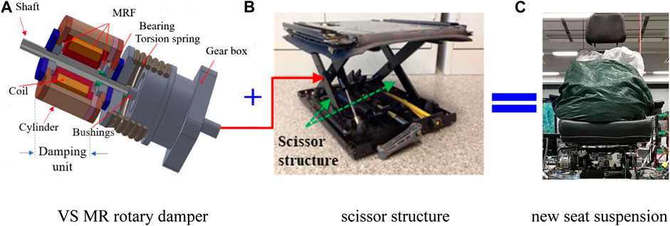
FIGURE 1. The structure and prototype of the VS MR suspension.
Assembling of the New Seat Suspension
Figure 1B shows the assembling of the VS MS rotary damper to the seat suspension. The seat suspension has two scissor structures at its two flanks, one of which will be installed with the VS MR damper. Figure 1B shows that the damper was installed to the left side of the seat suspension, specifically, the shaft of the VS MR damper is fixed to one beam of the scissor structure while the cylinder of the damper is fixed with the other one in the same scissor structure. When this seat is subjected to vertical vibration, the two beams of the scissor structure rotate relatively in opposite directions, which drives the rotary MR damper to rotate. In this way, the vertical linear vibration is transformed into rotational motions in the rotary damper.
Working Principle of the New Seat Suspension
The VS rotary MR damper is responsible for providing controllable stiffness to the seat suspension. The realization of the controllable stiffness relies on the cooperation between the spring and the damping variability provided by the damping unit. The damping of the MR damping unit increases gradually as the current applied to power the electromagnetic coil increases, accordingly, the relative rotation between the shaft and the cylinder of the damping unit will become increasingly difficult. In this case, the deformation of the torsional spring will increase under the same external excitation and the VS MR rotary damper will perform higher stiffness. The applied current controls the deformation of the torsional spring and thus the overall suspension stiffness. Specifically, the shaft can rotate easily with respect to its cylinder when the damping of the damping unit is small. In this case, the torsional spring will not perform any deformation, thereby the VS MR rotary damper demonstrates low stiffness. Alternatively, when the damping is large enough and the torque produced by the torsional spring cannot overcome the damping force, the damper cylinder has no relative motion with respect to the shaft and the torsional spring will be deformed during operation. In this scenario, the VS rotary damper performs the maximum stiffness. The medium stiffness which falls between the minimum and the maximum can be realized by adjusting the amount of the applied current.
Experimental Characterization
Characterization of MR Fluids
MRF used in this work is bought from Beijing Guohao Sensing Technology Research Institute, China (model: GH-MRF-250, density: 2.55 g cm−3). Its shear properties were measured using a rheometer (Physica MCR 301, the Anton Paar Company, Germany). Figure 2A shows the yield stress characteristics of the MRF with respect to different magnetic flux density. From this figure it can be seen that the increase of the magnetic flux density results in the increase of the yield stress of MRF. Figure 2B presents the viscosity information of MRF vs. shear rate. The viscosity in Figure 2B was measured without the presence of magnetic field and the shear rate was increased from 0.1 s−1 to 1,000 s−1. It is seen that the viscosity decreases sharply then tends to level off when the shear rate keeps increasing. Using the MRF, the MR damping unit shown in Figure 1A is able to perform controllable torque and accordingly, the output force generated by the whole VS MR damper can be controlled by the applied DC current.
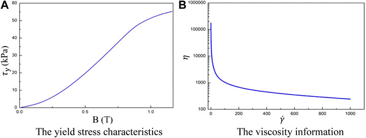
FIGURE 2. Property of the MRFs. (A) The yield stress characteristics (B) The viscosity information.
Dynamic Testing of the MR Seat Suspension Using an MTS Machine
The factors affecting the performance of the seat suspension mainly include the applied DC current to the magnetic coil of the rotary MR damper, the displacement amplitude and the loading frequency of the external vertical excitation. To investigate how these factors influence the suspension performance, dynamic tests were designed and conducted to explore the hysteretic behavior of the seat suspension under various currents, loading frequencies and amplitudes. With these tests, the equivalent damping and the effective stiffness of the seat suspension under different loading conditions can be calculated. The experimental setup using an MTS machine (Materials Test Systems, Landmark Servohydraulic Test Systems, MODEL 370.02, United States) is shown in Figure 3.
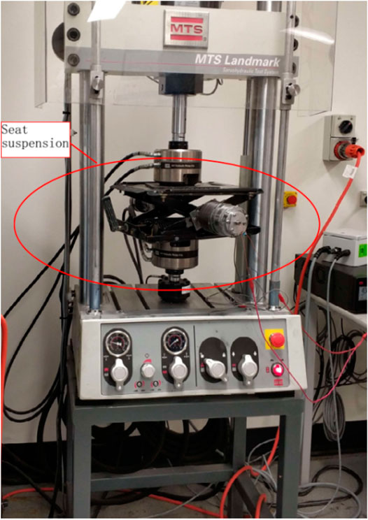
FIGURE 3. Experimental setup of the MTS testing.
Performance under different currents
The field-dependent properties are the most important features for a smart system as it determines its real time controllability. Therefore, a series of coil currents were used to energize the suspension to obtain its field-dependent behaviors. The sinusoidal signal with a frequency of 1 Hz and the displacement amplitude set as constant (5, 10, and 15 mm) was chosen as the excitation. For each testing case, the current was changed from 0 to 2 A with a step of 0.5 A. Therefore, a total of 15 cases were conducted. And for each testing, sufficient loops have been run before collecting the satisfactory data to guarantee the consistency. Figure 4 shows the axial force generated under various currents by the seat suspension in the time domain. It is in a vertical direction and it provides damping force to the seat suspension. It can be seen that the maximum force increases when the current is increased, which corresponds to the mechanism that the MR rotary damper shows increasing stiffness when the applied current increases.
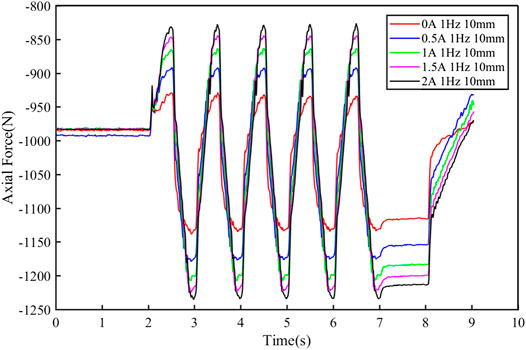
FIGURE 4. The generated force under different currents in time domain.
In order to provide a closer observation of the field-dependent property, Figure 5A–C plot the hysteresis loops of the force and displacement relationship under varied currents. Each contour was obtained under a constant amplitude of external excitation, i.e., 5, 10, and 15 mm, respectively. It is found that under certain excitation amplitudes, the stiffness increases obviously when the current is changed from 0 to 0.5 A, however, its increasing rates decrease when the current further increases. For different amplitudes, the same phenomenon in terms of the field-dependent property can be observed. For each hysteresis loop, the effective stiffness to be analyzed in the following section is obtained by calculating the slope of segment AB, as indicated in Figure 5A, using the following expression:
where n indicates the number of the dots on segment AB, (xn, yn)represents the coordinate of the nth dot. As segments AD and BC were generated by friction damping of the seat suspension, they are not included into the calculation of the effective stiffness.
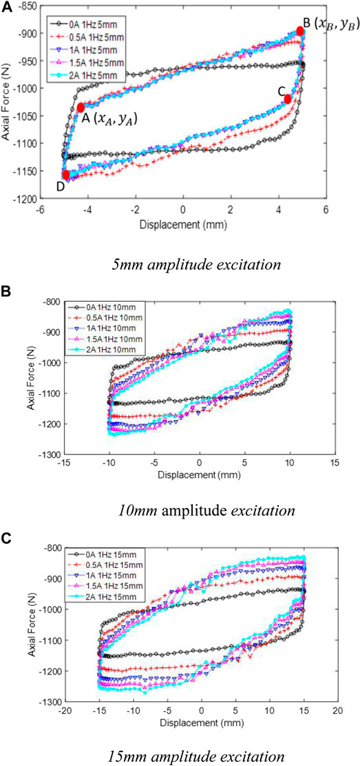
FIGURE 5. Force-displacement loops under different currents and amplitudes. (A) 5 mm amplitude excitation. (B) 10 mm amplitude excitation.(C) 15 mm amplitude excitation
Performance under different frequencies
To investigate the influence of the loading frequency on the suspension performance, a series of tests under various frequencies were conducted. The chosen frequencies for the test were 0.1, 1, 2, and 3 Hz. The displacement amplitude was set as 5 mm. And two current values (0A and 2 A) were chosen for this test.
Figure 6 shows the testing results under various frequencies with the current to be 0 A and Figure 7 provides its performance under 2 A. It can be seen that the loading frequency induces very slight influence on the hysteresis loops whether a current was applied or not, indicating that changing the loading frequency will not generate obvious influence on the peak force, the stiffness, or the damping. Therefore, it is concluded that the variations of loading frequency will not induce obvious change to the suspension performance. By comparing Figure 6 and Figure 7, it can be seen that a larger axial force was produced under 2 A. This can be explained by the field-dependent property as shown in Figure 5.
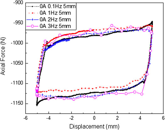
FIGURE 6. Force-displacement loops with no current applied under different frequencies.
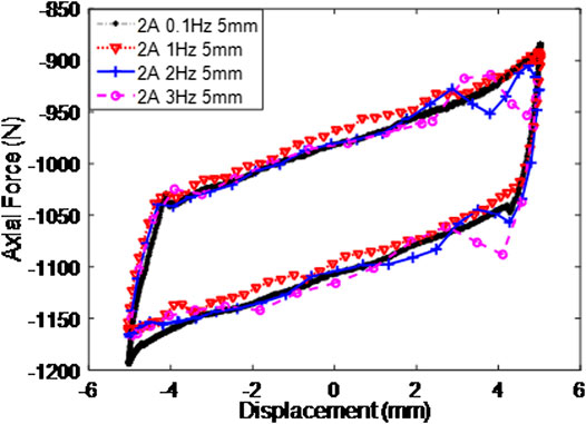
FIGURE 7. Force-displacement loops with 2 A current applied under different frequencies.
Dynamic property under different displacements
This sub-section tests the seat suspension performance under different displacements, the values of which were set as 5, 10, and 15 mm. The loading frequency was set as 1 Hz and the current was set as 0 A. The experimental results indicating the force-displacement relationship are shown in Figure 8.
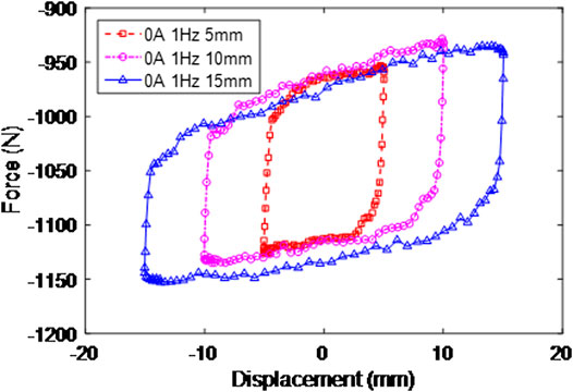
FIGURE 8. Force-displacement loops with no current applied under different excitation amplitudes.
The Analysis of the Effective Stiffness and Equivalent Damping
Effective stiffness analysis
For a seat suspension, the ride comfort experienced by the driver or passenger is an important indication to evaluate its performance. And the ride comfort is closely influenced by the stiffness achievable by the seat suspension. Figure 9 and Figure 10 present the calculated effective stiffness corresponding to different amplitudes and currents. The effective stiffness was calculated using the experimentally obtained data sets which have been plotted in Figure 5.
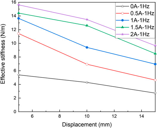
FIGURE 9. The effective stiffness of the MR seat suspension under different excitation amplitudes.
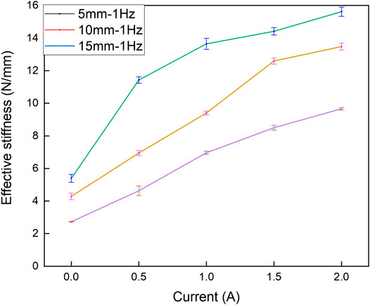
FIGURE 10. The effective stiffness of the MR seat suspension applied with different currents.
Figure 9 and Figure 10 plot the relationship between the effective stiffness and the displacement as well as the current. Both of these two figures show that for a fixed current, the stiffness reduces when the amplitude increases. However, when the amplitude is a constant, the stiffness increases as the current increases. But the increasing rate of the stiffness decreases when the current further increases, which verifies that the overall stiffness increases with the increasing current until a damping force is large enough to overcome the force generated by the torsional spring. The calculation results are consistent with the observations in Figure 5. The error bars with standard deviation for the calculated effective stiffness are also provided in Figure 10. They show that the effective stiffness for each group of experimental data is distributed centered on average with acceptable standard deviations.
Equivalent damping calculation
To study the energy-dissipation performance of this VS MR suspension, the equivalent viscous damping coefficient was calculated. The equivalent viscous damping coefficient can be obtained from (Li et al., 2000):
where EDC is the energy dissipated per cycle, or the area enclosed by the hysteresis loop, f is the loading frequency and
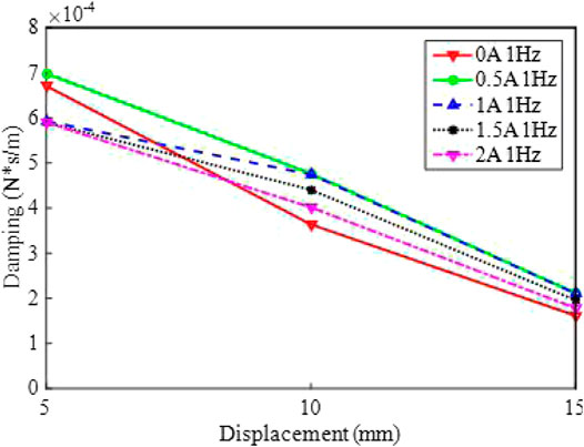
FIGURE 11. The equivalent damping of the MR seat suspension under different excitation amplitudes.
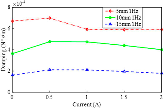
FIGURE 12. The equivalent damping of the MR seat suspension applied with different currents.
Figure 11 and Figure 12 plot the relationship between the equivalent damping coefficient and the current as well as the displacement amplitude. It is seen from Figure 11 that the damping coefficient shows a reducing trend with the increasing amplitude at a fixed current, however, for a constant amplitude, the viscous damping coefficient shows slight fluctuation which first increases and then drops down when the current further increases. Figure 12 also reflects the phenomenon that the viscous damping is sensitive to the current variation but less sensitive to the variations of displacement amplitude.
Evaluation of the Vibration Isolation Performance
Figure 13 shows the experimental setup to evaluate the vibration isolation performance of the proposed suspension system. Different excitations including random excitation and harmonic excitation were generated by a shaking table to excite the seat suspension. Two accelerometers were used to measure the accelerations of the excitation and the seat suspension, respectively. Considering that an appropriate controller is critically important for the suspension system to achieve good performance, a controller based on the short-time Fourier Transform (STFT) (Yang et al., 2020a) was developed and implemented, aiming to control the stiffness and realize the non-resonant control. The STFT algorithm is responsible for detecting the vibration frequency; then this excitation frequency will be compared with the natural frequency of the seat suspension. When the excitation frequency is close to the natural frequency of the seat suspension, the stiffness of the seat suspension will be adjusted to shift its natural frequency away from the excitation frequency to avoid resonance. Upon the establishment of the controller, experimental evaluation of the seat suspension was conducted. The acceleration of the seat suspension as well as the transmissibility are the main evaluation criteria. The acceleration signal measured from the shaking table was sent to the controller for processing to determine the dominant vibration frequency. The frequency controller then calculates the desired control output through STFT algorithms and sends it to a power amplifier. The amplified current was then sent to the damper to control its stiffness. During the experiment, three different suspensions were evaluated, i.e., passive-off, passive-on, and semi-active suspensions. Passive-off suspension means there is no current applied to the damper; passive-on suspension means a constant current (2 A) was applied to the damper; and semi-active suspension means the suspension is controlled by the STFT controller in real time. The passive-on and passive-off suspensions are given as reference to compare with the semi-active suspensions. The evaluation results are presented in Figure 14 and Figure 15B.
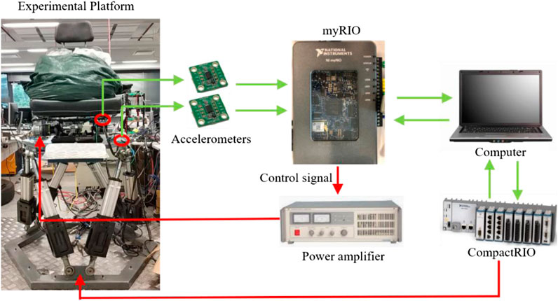
FIGURE 13. Experimental setup for evaluating the vibration isolation performance (CompactRIO: Crio-9074, mit 400 MHz CPU, 128 MB DRAM, 256 MB Speicher, FPGA mit 2 Millionen Gattern, eight Slots).
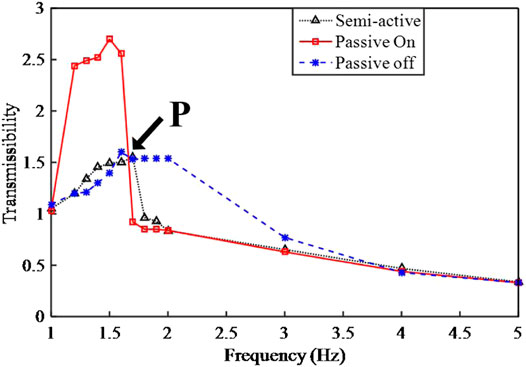
FIGURE 14. Vibration transmissibility of the three different suspensions.
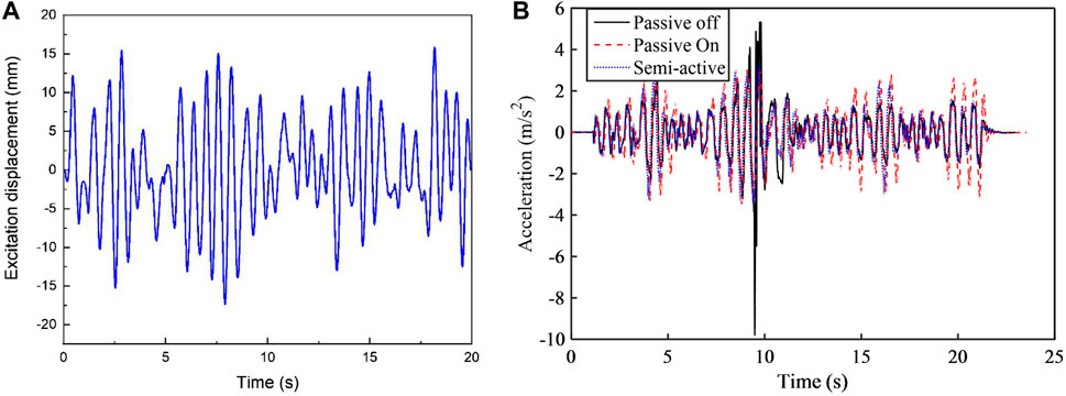
FIGURE 15. Acceleration performance of the random excitation. (A) excitation, (B) response.
Figure 14 illustrates the acceleration transmissibility of the three suspensions. As it is the ratio of the seat acceleration to the excitation acceleration, the lower its value means the better its performance. It can be seen that the natural frequency of the passive-off case is smaller than that of the passive-on case. That is because the stiffness of the VS rotary MR damper increases when the applied current increases and accordingly, the natural frequency increases. The two transmissibility from the passive-on and passive-off cases have an intersected frequency, as indicated by letter P in Figure 14. It can be seen that the transmissibility under the passive-on case is the lowest when the excitation frequency is less than this intersected frequency, otherwise, the transmissibility under the passive-off case is the lowest. Therefore, a minimum transmissibility can be generated by connecting these two segments. Then it is observed that the transmissibility of the semi-active control mode can just track the minimum transmissibility: it almost keeps consistent with the transmissibility under the passive-on case before the intersected frequency and then drops down to the transmissibility of the passive-off case once the excitation frequency is higher than the intersected frequency. Therefore, it can be concluded that the VS MR seat suspension under the semi-active control performs best at reducing the acceleration response. A video indicating the performance comparing the passive suspension and semi-active suspension under three representative frequencies, i.e., 1.3, 1.5, and 1.6 Hz is provided as a supporting material. Figure 15B presents the acceleration responses of the seat suspensions under random excitation. The random excitation is generated by the method presented in Ref (Yang et al., 2000c), which has been widely adopted to evaluate the suspension performance and shown in Figure 15A. This evaluation result further proves that the suspension acceleration of the semi-active suspension remains the smallest for the whole-time history compared with the other two passive cases.
In order to better understand the improvement of the semi-active seat suspension over the passive ones, ISO 2631is introduced as shown in Table 1 (International Organization for Standardization, 1997) which has categorized the comfort levels according to a human’s likely reactions to various magnitudes of vibration. Accordingly, the Z-axial weighted RMS values which have considered the passengers’ ride comfort were calculated and tabulated in Table 2. It can be seen from Table 2 that the comfort level achieved by the passive off suspension and the passive on suspension is level C which represents “fairly uncomfortable,” however, the comfort level achieved by the semi-active suspension is level B which indicates “a little uncomfortable.” The comparison has demonstrated that semi-active suspension has brought a higher level of comfort to the passengers.
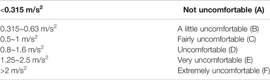
TABLE 1. Approximate indications of likely reactions to various magnitudes of vibration.
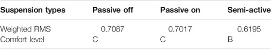
TABLE 2. The weighted RMS values of accelerations for the three suspensions.
Conclusion
A rotary MR damper which is able to perform variable stiffness characteristics was successfully developed and then used to implement a semi-active seat suspension, aiming to overcome the drawback of a traditional MR damper that it cannot realize the non-resonance control. The seat suspension was then characterized using MTS machine in terms of the field-dependent response, the amplitude-dependent response, and the frequency-dependent responses. The testing results demonstrated that the stiffness and the generated force increase in response to the increasing current but decrease slightly when the displacement amplitude increases. This variability of the stiffness indicate that the new seat suspension is able to satisfy the conflicting requirement of the stiffness, i.e., it can provide not only high stiffness to guarantee the riding stability but also low stiffness to achieve better ride comfort. In addition, the suspension stiffness is not sensitive to the variations of the loading frequency. As for the damping property, the experimental results show that the equivalent damping coefficient decreases when the displacement amplitude increases and that the applied increasing current induces a slight influence on the equivalent damping. The vibration isolation experiments have compared the responses of different suspensions. The results have demonstrated that the seat suspension with the semi-active control performs the best in reducing the suspension acceleration.
Data Availability Statement
The raw data supporting the conclusions of this article will be made available by the authors, without undue reservation.
Author Contributions
SS and JY contributed equally to this work. SS, JY, and PW: methodology, software and formal analysis. SS, and WL: conceptualization. SS, JY, PW, MN, and LS: validation and investigation. SS, SZ, and WL: resource and data curation. SS and JY: writing–original draft preparation and visualization. All authors: writing–review and editing. SS, and WL: supervision and project administration.
Funding
This research is supported by ARC Linkage Project (Grand No. LP150100040), JSPS Grant-in-Aid for Research Activity Start-up (Grand No. 19K23476), for Young researcher B (Grand No. 20K14688) and for JSPS fellowship (Grand No. 19F19712), and the National Key R&D Program of China (Grant Nos. 2018YFB1201703).
Conflict of Interest
The authors declare that the research was conducted in the absence of any commercial or financial relationships that could be construed as a potential conflict of interest.
References
Abe, H., Naka, T., Sato, K., Suzuki, Y., and Nakano, M. (2019). Shape-controlled syntheses of magnetite microparticles and their magnetorheology. Int. J. Mol. Sci. 20, 3617. doi:10.3390/ijms20153617
Alfadhli, A., Darling, J., and Hillis, A. J. (2018). An active seat controller with vehicle suspension feedforward and feedback states: an experimental study. Appl. Sci. 8, 603. doi:10.3390/app8040603
Bai, X.-X., Hu, W., and Wereley, N. M. (2013). Magnetorheological damper utilizing an inner bypass for ground vehicle suspensions. IEEE Trans. Magn. 49, 3422–3425. doi:10.1109/tmag.2013.2241402
Bai, X.-X., and Wereley, N. M. (2014). “Magnetorheological impact seat suspensions for ground vehicle crash mitigation,” in SPIE smart structures and Materials + nondestructive evaluation and health monitoring, San Deigo, CA, April 2014 (International Society for Optics and Photonics).
Carlson, J. D., and Jolly, M. R. (2000. MR fluid, foam and elastomer devices. Mechatronics 10, 555–569. doi:10.1016/s0957-4158(99)00064-1
Choi, S.-B., and Han, Y.-M. (2007). Vibration control of electrorheological seat suspension with human-body model using sliding mode control. J. Sound Vib. 303, 391–404. doi:10.1016/j.jsv.2007.01.027
Choi, Y.-T., and Wereley, N. M. (2005). Biodynamic response mitigation to shock loads using magnetorheological helicopter crew seat suspensions. J. Aircraft, 42, 1288–1295. doi:10.2514/1.6839
Deng, H., Deng, J., Yue, R., Han, G., Zhang, J., Ma, M., et al. (2019). Design and verification of a seat suspension with variable stiffness and damping. Smart Mater. Struct. 28. doi:10.1088/1361-665x/ab18d4
DETR, (2000), Tomorrow’s Roads-Safer for Everyone. London, United Kingdom: Department of the Environment, Transport and the Regions.
Eshaghi, M., Rakheja, S., and Sedaghati, R. (2015). An accurate technique for pre-yield characterization of MR fluids. Smart Mater. Struct. 24. doi:10.1088/0964-1726/24/6/065018
Gad, S., Metered, H., Bassuiny, A., and Abdel Ghany, A. (2017). Multi-objective genetic algorithm fractional-order PID controller for semi-active magnetorheologically damped seat suspension. J. Vib. Contr. 23, 1248–1266. doi:10.1177/1077546315591620
Guo, C., Gong, X., Zong, L., Peng, C., and Xuan, S. (2015). Twin-tube-and bypass-containing magneto-rheological damper for use in railway vehicles. Proc. Inst. Mech. Eng. - Part F J. Rail Rapid Transit 229, 48–57. doi:10.1177/0954409713497199
Haworth, N. L., Triggs, T. J., and Grey, E. M. (1998). Report No. CR72. Driver fatigue: concepts, measurement and crash countermeasures. Canberra, CBR: Federal office of road safety Monash University.
Hu, G., Ru, Y., and Li, W. (2014). Design and development of a novel displacement differential self-induced magnetorheological damper. J. Intell. Mater. Syst. Struct. 26, doi:10.1177/1045389X14533429
Legislative Assembly of Queensland: Parliamentary Travelsafe Committee, (2005). Report No. 43. Driving on empty: fatigue driving in queensland. Brisbane, BNE:Queensland Government.
International Organization for Standardization, (1997). Mechanical vibration and shock—evaluation of human exposure to whole-body vibration—Part 1: general requirements. Geneva, CH: ISO International Standard.
Li, W. H., Du, H., Chen, G., Yeo, S. H., and Guo, N. (2003). Nonlinear viscoelastic properties of MR fluids under large-amplitude-oscillatory-shear. Rheol. Acta 42, 280–286. doi:10.1007/s00397-002-0285-4
Li, W., Yao, G., Chen, G., Yeo, S., and Yap, F. (2000). Testing and steady state modeling of a linear MR damper under sinusoidal loading. Smart Mater. Struct. 9, 95. doi:10.1088/0964-1726/9/1/310
Li, Y., Li, J., Li, W., and Du, H. (2014). A state-of-the-art review on magnetorheological elastomer devices. Smart Mater. Struct., 23, 123001. doi:10.1088/0964-1726/23/12/123001
Liu, X., Wang, N., Wang, K., Huang, H., Li, Z., Sarkodie-Gyan, T., et al. (2019). Optimizing vibration attenuation performance of a magnetorheological damper-based semi-active seat suspension using artificial intelligence. Front. Mater. 6, 269, doi:10.3389/fmats.2019.00269
Maciejewski, I., Krzyzynski, T., and Meyer, H. (2018). Modeling and vibration control of an active horizontal seat suspension with pneumatic muscles. J. Vib. Contr. doi:10.1177/1077546318763435
Motmans, R. (2012). Reducing whole body vibration in forklift drivers. Work, 41 Suppl 1, 2476–2481. doi:10.3233/WOR-2012-0484-2476
Nakano, M. (2015). MR effect enhancement of bidisperse MR fluids containing micron-and nano-sized iron particles. Bull. Am. Phys. Soc., 60.
National Hazard Exposure Worker Surveillance, (2009). Vibration exposure and the provision of vibration control measures in Australian workplaces. Safe Work Australia, Available at: https://www.safeworkaustralia.gov.au/doc/national-hazard-exposure-worker-surveillance-vibration-exposure-and-provision-vibration-control.
Nguyen, H. Q., Choi, S.-B., Hiep, L. D., and Tuan, L. D. (2019). Material characterization of MR fluid on performance of MRF based brake. Front. Mater., 6, 125. doi:10.3389/fmats.2019.00125
Ning, D., Du, H., Sun, S., Li, W., and Li, W. (2018). An energy saving variable damping seat suspension system with regeneration capability. IEEE Trans. Ind. Electron. 65, 8080–8091. doi:10.1109/tie.2018.2803756
Ning, D., Sun, S., Zhang, F., Du, H., Li, W., and Zhang, B. (2017). Disturbance observer based Takagi-Sugeno fuzzy control for an active seat suspension. Mech. Syst. Signal Process. 93, 515–530. doi:10.1016/j.ymssp.2017.02.029
Phu, D. X., Quoc Hung, N., and Choi, S.-B. (2018). A novel adaptive controller featuring inversely fuzzified values with application to vibration control of magneto-rheological seat suspension system. J. Vib. Contr. 24, 5000–5018. doi:10.1177/1077546317740479
Sun, S., Ning, D., Yang, J., Du, H., Zhang, S., Li, W., et al. (2017). Development of an MR seat suspension with self-powered generation capability. Smart Mater. Struct. 26, 085025. doi:10.1088/1361-665x/aa76b6
Sun, S., Tang, X., Yang, J., Ning, D., Du, H., Zhang, S., et al. (2019). A new generation of magnetorheological vehicle suspension system with tunable stiffness and damping characteristics. IEEE Trans. Ind. Inf. 15, 4696–4708. doi:10.1109/tii.2018.2890290
Tu, J., Li, Z., Zhang, J., Gao, K., Liao, J., and Gao, J. (2019). Development, test, and mechanical model of the leak-proof magnetorheological damper. Front. Mater., 6, 118. doi:10.3389/fmats.2019.00118
Wereley, N. M., Choi, Y.-T., and Singh, H. J. (2011). Adaptive energy absorbers for drop-induced shock mitigation. J. Intell. Mater. Syst. Struct. 22, 515–519. doi:10.1177/1045389x10393767
Yang, B., Chen, S., Sun, S., Deng, L., Li, Z., Li, W., et al. (2020a). Vibration suppression of tunnel boring machines using non-resonance approach. Mech. Syst. Signal Process. 145, 106969. doi:10.1016/j.ymssp.2020.106969
Yang, J., Christie, M., Sun, S., Ning, D., Nakano, M., Li, Z., et al. (2020b). Integration of an omnidirectional self-powering component to an MRE isolator towards a smart passive isolation system. Mech. Syst. Signal Process., 144, 106853. doi:10.1016/j.ymssp.2020.106853
Yang, J., Ning, D., Sun, S., Zheng, J., Lu, H., Nakano, M., et al. (2020c). A semi-active suspension using a magnetorheological damper with nonlinear negative-stiffness component. Mech. Syst. Signal Process., 147, 107071. doi:10.1016/j.ymssp.2020.107071
Yu, J., Dong, X., Wang, X., Pan, C., and Zhou, Y. (2019). Asymmetric dynamic model of temperature-dependent magnetorheological damper and application for semi-active system. Front. Mater. 6, 227. doi:10.3389/fmats.2019.00227
Yu, J., Dong, X., Zhang, Z., and Chen, P. (2018). A novel scissor-type magnetorheological seat suspension system with self-sustainability. J. Intell. Mater. Syst. Struct. 30, 1045389X1775425. doi:10.1177/1045389X17754256
Yu, M., Dong, X., Choi, S., and Liao, C. (2009). Human simulated intelligent control of vehicle suspension system with MR dampers. J. Sound Vib. 319, 753–767. doi:10.1016/j.jsv.2008.06.047
Yu, M., Yang, P., Fu, J., Liu, S., and Choi, S.-B. (2016). A theoretical model for the field-dependent conductivity of magneto-rheological gels and experimental verification. Sensor Actuator Phys. 245, 127–134. doi:10.1016/j.sna.2016.05.008
Keywords: seat suspension, variable stiffness, compact rotary MR damper, vibration control, non-resonance
Citation: Sun S, Yang J, Wang P, Nakano M, Shen L, Zhang S and Li W (2021) Experimental Study of a Variable Stiffness Seat Suspension Installed With a Compact Rotary MR Damper. Front. Mater. 8:594843. doi: 10.3389/fmats.2021.594843
Received: 14 August 2020; Accepted: 25 January 2021;
Published: 19 February 2021.
Edited by:
Miao Yu, Chongqing University, ChinaCopyright © 2021 Sun, Yang, Wang, Nakano, Shen, Zhang and Li. This is an open-access article distributed under the terms of the Creative Commons Attribution License (CC BY). The use, distribution or reproduction in other forums is permitted, provided the original author(s) and the copyright owner(s) are credited and that the original publication in this journal is cited, in accordance with accepted academic practice. No use, distribution or reproduction is permitted which does not comply with these terms.
*Correspondence: Shuaishuai Sun, sssun@ustc.edu.cn; Weihua Li, weihuali@uow.edu.au