From Polymer to Magnetic Porous Carbon Spheres: Combined Microscopy, Spectroscopy, and Porosity Studies
 Federico Cesano
 Sara Cravanzola
 Valentina Brunella
 Alessandro Damin
 Domenica Scarano
- Department of Chemistry and NIS (Nanostructured Interfaces and Surfaces), Interdepartmental Centre and INSTM Centro di Riferimento, University of Torino, Torino, Italy
The facile preparation of polymer waste-derived microporous carbon microspheres (SBET ~800 m2/g) 100–300 μm in size, is reported at first. We have taken advantage of both, the crosslinked nature and the porous texture of the poly(4-ethylstyrene-co-divinylbenzene) microspheres, which allow the incoming anions and cations present in liquid media to enter and to remain segregated into the pores of the polymer microspheres as soon as the solvent is removed. Interestingly, the ZnCl2 phase, when incorporated in the microporous molecular architecture of the polymer, prevents the collapsing of the pore structure of thermosetting polymer spheres during the pyrolysis occurring at 800°C and acts as an activating agent of the carbon phase under formation, being responsible for the formation of an extended meso- and macroporosity (30–200 and 300–1,000 Å ranges). More interestingly, porous carbon microspheres with magnetic properties have been prepared from the ZnCl2-activated porous carbon spheres after impregnation with Fe nitrate solution and thermal treatment at 800°C. A multi-technique methodology to characterize more extensively carbons at the micro/nanoscale is reported in the paper. More in detail, the morphology, structure, porous texture, and the surface properties of the carbon and of the magnetic carbon microspheres have been investigated by scanning and transmission electron microscopy, atomic force microscopy, X-ray diffraction, N2 physisorption, diffuse reflectance UV-Vis, Raman and infrared spectroscopies. Furthermore, magnetic properties have been revealed at the nano- and at the macroscale by magnetic force microscopy and simple magnetically guided experiments by permanent magnets. The multi-technique methodology presented in the paper allows in elucidating more extensively about the different characteristics of activated carbons. Notwithstanding the huge amount of literature on activated carbons, the precise control of both the structure and the surface has, for the most part, hidden the relevance of other properties at the molecular scale of the assembled architectures. On the other hand, recent studies indicate that by molecular design, nanostructured, and porous carbonaceous materials could also be rationally proposed.
Introduction
Porous activated carbon materials have attracted high interest in the past, due to their remarkable physical and chemical properties, including chemical inertness, mechanical stability, electrical conductivity, and biocompatibility (Lu et al., 2017; Wang et al., 2018). Activated carbons are now used in a broad range of industrial applications, including the gas/air cleaning from pollutants, and catalysis (Benzigar et al., 2018). Another field of application is the treatment/purification of liquids, like the water decontamination, which is of importance in the beverage, food, and pharmaceutical industries. More recent applications for C-doped systems have been also found in other fields, including energy fields and carbon capture (Calvo-Muñoz et al., 2016; Benzigar et al., 2018; Wang et al., 2018). In general, the choice of the most appropriate kind of activated carbon, for a specific use, depends primarily on its physical-chemical properties. When considering a material for such uses, the surface area, the pore-size, and the connectivity between the pores are by far the most relevant parameters. In order to tailor such specific properties, recent efforts have been made to design porous carbon materials with well-defined architectures, controllable pore size, and surface area (Borchardt et al., 2017).
As far as the size and shape control of the carbon materials is concerned, many porous carbons have been successfully obtained through templating methods using hard templates (Benzigar et al., 2018), such as mesoporous silica, zeolites and polymer microspheres, or soft templates, such as copolymer surfactants (Lu et al., 2017). Polymer spheres not only can allocate other systems (metal oxides and other structures in the porous channels) (Cesano et al., 2012a; Wang et al., 2018), but the formation of 3D ordered macroporous materials is promoted (Sadakane et al., 2010, 2012). Moreover, the templating routes have been used to synthesize hollow carbon spheres by coating a carbon precursor on a hard template core, which has been then removed (Liu et al., 2011) or by templated carbonization of glucose (Zhang et al., 2011), or of resorcinol–formaldehyde resins (Feather and Harris, 1973; Kraiwattanawong et al., 2011). The template fabrication of core-shell magnetic mesoporous carbon microspheres in 3-Dimensional ordered macroporous silicas has been also reported (Wang et al., 2014). In general, the preparation processes from the templating approaches are usually difficult and cost/time-consuming, which limit their practical applications (Lu et al., 2017). Notwithstanding feasible strategies may be adopted starting from cheaper material, such as polymer precursors (Cesano et al., 2012b; Fenoglio et al., 2015; Xu et al., 2017), biomaterials (Azevedo et al., 2007; Hadidi et al., 2017), and wastes (Franzoso et al., 2017; Nisticò et al., 2018) and performing simple processes, such as chemical and thermal treatments (Molina-Sabio and Rodriguez-Reinoso, 2004; Zhang et al., 2010; Rosas et al., 2014).
On the other hand, materials made by porous carbons together with inorganic compounds and oxides can be synthesized. Taken together, the two systems can show enhanced functionalities due to synergistic effects between multiple components, excellent performances in various fields, including biofuel cell, energy storage, fluorescent, or electronic biosensors and as adsorbents (Cheng et al., 2014; Piñeiro-Prado et al., 2016). One useful example is that of the composite core–shell carbon spheres (Ag/C, Au/C) that have been obtained from the hydrothermal treatment of glucose (Sun and Li, 2004, 2005; Liu et al., 2011) and carbon nanospheres, 70-140 nm in size, obtained from cyclodextrins and maltodextrins (Shin et al., 2008; Zanetti et al., 2016; Anceschi et al., 2017). Meanwhile, the combination of carbon phases with oxides (TiO2, ZnO, SnO2, etc.) may offer a porous and nanostructured texture (Cesano et al., 2008a; Rahman et al., 2010) that makes the composite material catalytically photoactive under visible light (Cesano et al., 2008a, 2012a; Uddin et al., 2014; Cravanzola et al., 2015; Cravanzola et al., 2017).
Other useful examples to this context are those provided by carbons with magnetic properties. Colloidal and magnetic carbon spheres have drawn also particular attention because of their peculiar potential applications in catalysis (methanol oxidation) (Zhang et al., 2011), energy conversion and storage (Liu et al., 2011) (fuel cells, gas storage, and separation, and lithium-ion batteries; Yi et al., 2011), molecular adsorption/segregation (Liu et al., 2010; Yin et al., 2011; Lu et al., 2017).
Moreover, magnetic iron-based nanoclusters have been incorporated inside the hierarchical porous carbon microspheres to give to the obtained composites a magnetic separation property (Cesano et al., 2016; Lu et al., 2017). This provides a simple method to an easy removing and recycling of the adsorbents by means of an external magnet. Furthermore, multilayered structures made by porous carbon microspheres with embedded magnetic nanoparticles are known to show an enhanced high surface area, large pore volume together with superior adsorption capability, a fast adsorption rate and facile separation (Lu et al., 2017). The stability of magnetic nanoparticles is also greatly enhanced when they are covered by carbon layers, in a core-shell structure, thus preventing the nanoparticles from agglomeration phenomena (Jafari et al., 2014). Hence, by combining the advantages of cheap activated carbon and the properties of the magnetic particles, it is possible to fabricate new adsorbents incorporating iron-based particles, being the high surface area, the suitable pore size and the separability the main goals to achieve (Yang et al., 2008).
Herein, we report a simple method for fabricating magnetic carbon materials, moving from a copolymer of polystyrene and divinylbenzene (PS-co-DVB). Firstly, we demonstrate that microporous carbon spheres with controlled sizes and porous textures can be prepared from low-cost polymer waste, that is a commercially available, inexpensive and easy to handle resin. Secondly, the as-prepared spheres possess a large pore volume, a relatively high surface area and a wide mesopore size distribution, as obtained from gas sorption isotherms. Together with porosimetry and spectroscopies (Raman, FTIR and UV-Vis), microscopies (SEM, TEM, and AFM/MFM) provide a comprehensive multitechnique approach for the textural imagining. Lastly, the mesoporous carbon microspheres with magnetic properties can be produced after additional treatment with iron salt and annealing. Therefore, the present study suggests not only the higher-value use of polymer wastes and clarifies the relationship between the surface properties/porous texture of the polymer-derived carbons, but, more interestingly, it highlights the fact that the mesoporous properties, together with the magnetic character of the hybrid carbon, can make it suitable for constructing multifunctional materials with magnetically driven processes. On the other hand, the topic of the molecular design of porous carbons, escaping from the simple concept of the structure/surface control, is of tremendous interest (Liu et al., 2015; Borchardt et al., 2017). Aiming to tailor and adjust the intrinsic characteristics (i.e., electrical conductivity, bandgap, enantioselectivity and other optical properties, interaction with specific guest molecules, etc.), the carbon materials with attained functionality can emerge in new application fields.
Experimental
Materials
ZnCl2 has been dissolved in ethanol at 110°C (10:3 weight ratio of ZnCl2), mixed to polymer in the 10:1 w/w and then stirred and dried at 80°C for 24 h, according to the preparation procedure of the carbon microspheres summarized in Scheme 1. Following this, the PS-co-DVB polymer microspheres either pure (Scheme 1, Step A) or containing ZnCl2 salt as an activating agent (Scheme 1, Step B1) were produced as the result of the thermal treatment under N2 gas flow up to 800°C for 5 h. Then, the ZnCl2-activated carbon microspheres coming from Step B1 have been impregnated with a 0.011 M ethanol solution of Fe(NO3)3 for 20 h at RT and thermal treated under N2 gas flow up to 800°C for 5 h (Scheme 1, Step B2).
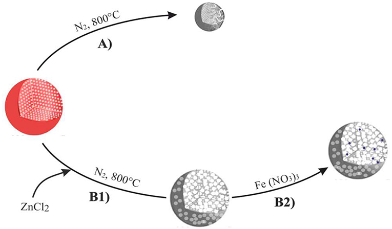
Scheme 1. Preparation steps of the carbon microspheres upon thermal treatment/activation at 800°C. Thermal treatment under N2 (Step A), chemical activation by ZnCl2 (step B1), subsequent impregnation with a 0.011M solution of Fe(NO3)3 and thermal treatment under N2 gas flow at 800°C for 5 h (step B2).
Methods
Microscopy and Structural Analysis
The microspheres were analyzed at the different steps of preparation. The morphology and the structure of the samples were investigated using scanning electron microscopy (SEM), transmission electron microscopy (TEM) and atomic force microscopy (AFM). More in detail, the images were taken on: (i) a Zeiss Evo 50 SEM instrument operating at 30 kV, (ii) a JEOL 3010-UHR HRTEM microscope operating at 300 kV, equipped with a 2 × 2 k pixels Gatan US1000 CCD camera, (iii) Nanosurf Easyscan2 AFM instrument, equipped with a 10 μm scan-head, high-performance anti-vibration platform in an acoustically insulated enclosure and Faraday cage. Reciprocal lattices and electron diffraction patterns were obtained by means of CaRine Crystallography 3.1 simulation package. Sections of the Fe-based microspheres were also obtained by adopting the ultramicrotomy method to explore the inner structure of the material. Briefly, microspheres magnetically guided to the bottommost region of an Eppendorf tube were embedded with the epoxy resin to constitute a block specimen, which is then cross-sectioned after curing. The thin microtomed slices, containing the cross-sections of the microsphere were obtained by using a regular gemgrade diamond knife. Samples were then investigated by SEM. Phase composition of microspheres was obtained by XRD analysis on a PANalytical X'Pert PRO diffractometer equipped with a Cu source and a Ni filter, in a standard Bragg–Brentano geometry. The profile fitting method in the whole XRD patterns has been adopted to determine the phase compositions and crystal sizes (JADE 6.5, Materials Data). Vibrational properties were investigated by: (i) Renishaw inVia Raman microscope equipped with 785 nm (diode laser) and 514 nm (Ar+) laser-lines and ii) Renishaw Raman InVia spectrophotometer with 442 nm laser-line. Raman spectra were collected by 20× objectives, <1 mW at the sample and with an in-house made rotating configuration to avoid sample heating and damaging (Signorile et al., 2018).
Porosity and Porous Texture Analysis
N2-adsorption/desorption isotherms were obtained at 77 K (Micromeritics ASAP 2020 instrument) to determine the porosity properties of the materials at the different stages of preparation. Before analysis, the samples, as obtained following the before described procedure, were further outgassed overnight at RT (for the starting PS-co-DVB polymer) or at 400°C (for the resulting carbon materials after the thermal treatments). The surface area (SBET) was calculated by the Brunauer–Emmett–Teller (BET) equation (in the relative pressure range of 0.05–0.25 p/p0). Total pore volume was determined from the amount of N2 adsorbed at the 0.98 p/p0. Micropore surface area and volume were calculated from N2 adsorption isotherms using the Carbon Black STSA t-plot equation. Mesopore volume (Vmeso) was calculated by subtracting the micropore volume (Vmicro) from the total pore volume (Vtot). The pore size distributions (PSDs) were derived from the N2 adsorption isotherms using a non-negative least squares fitting on the adsorption isotherm data by applying the density functional theory (DFT) method (N2-DFT model, slit geometry) by means of the MicroActive Datamaster 5 software (Micromeritics).
Investigation of Magnetic Properties
Magnetic force microscopy (MFM) images were obtained on a microtomed cross-section of a Fe-based microsphere in a dual-pass mode performed by using the same AFM equipment. The morphological properties were obtained in the intermittent contact mode during a first scan, while the MFM phase imaging was operated in the second scan, at constant-height (H) above the surface with the same magnetic probe (SSS-MFMR, Nanosensors; with a tip radius of 15 nm by using a resonant frequency of 75 kHz) without bias or external magnetic field applied, by monitoring the shifting of the phase and of the amplitude signals. The two scans allow to discriminate short (van der Waals, i.e., topography) and longer range (magnetic) interactions. The magnetic tip probe was magnetized by an external magnet (magnetization along the tip-axis) and tested on a magnetic grid prior to measurements.
Analysis of Spectroscopic Properties
The optical properties of the samples have been obtained by means of Diffuse Reflectance (DR) UV–vis-NIR spectrophotometer (Varian Cary UV 5000 equipped with a diffuse reflectance sphere) in the 14,000–40,000 cm−1 range (about 700–250 nm wavelength range). The samples were diluted in BaSO4 to provide detectable Kubelka–Munk values. FTIR spectra have been recorded on a Perkin Elmer Spectrum 100 in the attenuated total reflectance (ATR) mode with a diamond crystal and in the transmission mode on KBr pellets using 32 scans per spectrum with a resolution of 4 cm−1 to detect the low wavenumber region (700–450 cm−1 range).
Thermal Analysis
Thermogravimetric measurements (TGA, Q600-SDT TA instruments) were performed under air up to 800°C (heating rate 15°C/min) to quantify the iron oxide loading.
Results and Discussion
Morphology, Structure, and Textural Properties of the Samples
Low-resolution SEM images of the material at the different steps of preparation are shown in Figures 1a–d while the corresponding size distributions are illustrated in the right panel (Figures 1a′-d′).
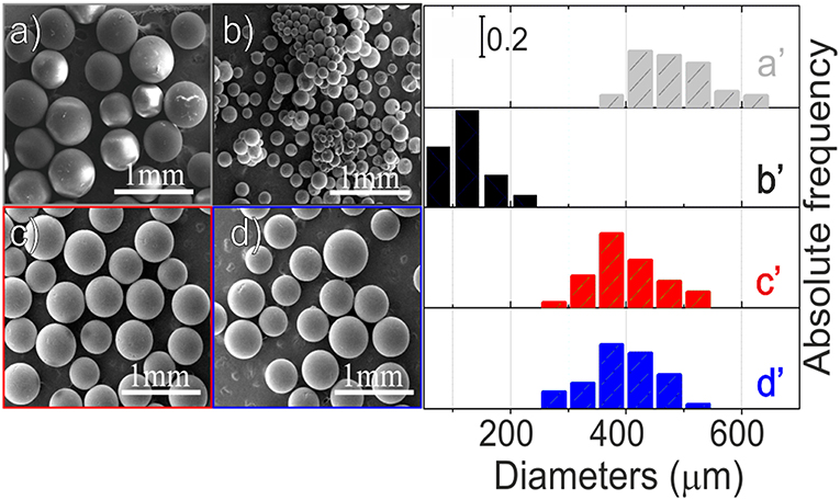
Figure 1. Low-resolution SEM images (left panel) of: PS-co-DVB spheres (a), PS-co-DVB spheres after pyrolysis at 800°C for 5 h (b), ZnCl2 activated carbon microspheres, after thermal treatment at 800° under N2 (c), carbonized ZnCl2/carbon microspheres after impregnation with Fe(NO3)3 and then thermal treatment at the same temperature (d); size distributions (right panel) of spheres at the different steps of preparation: polymer material before (a′) and after pyrolysis at 800°C (b′), ZnCl2-activated microspheres (c′) and the same ZnCl2-based spheres impregnated with Fe(III) after their thermal treatments at 800°C (d′).
From this figure, it is evident that, after the pyrolysis at 800°C (Figure 1b), the PS-co-DVB spheres maintain their spherical shape, but they are smaller in size, thus changing from 350-600 to <250 μm. Conversely, when the ZnCl2-embedded polymer is taken under consideration, after the thermal treatment under N2 gas flow at 800°C, the situation is completely different (Figure 1c). The sample is still formed by spherical particles, but their diameters, ranging in the 250–550 μm interval, are closer to those of the raw material spheres. Notice that the sizes are retained also after the thermally treated Fe(III)-impregnated carbon spheres (Figure 1d). From these images, the remarkable role of the embedded ZnCl2 phase into the pores, in preserving the structure of the spheres upon the thermal treatment at 800°C under N2 gas flow, can be highlighted. However, at this level of magnification, nothing more can be inferred.
SEM and AFM images of the raw copolymer and of the carbon spheres at the different steps of preparation are shown in Figure 2. A polymer sphere, showing cracks and an apparently smoothed surface (SEM images in Figures 2a,a′), reveals its ultimate nature of assembled rounded domains, with sizes in the 0.1–0.3 μm range, as AFM imaged in Figure 2a″. Some copolymer spheres are SEM imaged after pyrolysis at 800°C for 5 h (Figures 2b,b′). Together with the before observed shrinkage of particles, also the rough surface, the occurrence of deep cracks, wrinkles, and folds at the surface, can be highlighted. Some more, from the AFM analysis, the assembling of the small nanoparticles is observed (Figure 2b″). ZnCl2-embedded spheres are SEM and AFM imaged after the thermal treatment at 800°C for 5 h in Figures 2c,c″. An apparent flatter surface, interrupted by small cracks of irregular shape, is obtained at low resolution (Figures 2c,c′), but a more irregular morphology, made of uneven ills, relatively large folds and small grains, whose edges are reasonably responsible for the porosity, is shown at the nanometric scale (Figure 2c″). Similar considerations can be made for the thermally annealed ZnCl2-embedded spheres after the impregnation with Fe nitrate, which behave in the same way as the sample before iron impregnation (Figures 2d,d″).
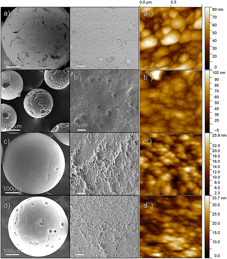
Figure 2. Low-resolution, higher resolution SEM and AFM images of the surface of the microspheres: raw copolymer (a,a′,a″); pyrolyzed PS-co-DVB (b,b′,b″); ZnCl2-embedded copolymer (c,c′,c″); and ZnCl2-carbon microspheres after impregnation with Fe nitrate solution and thermal treatment at 800°C (d,d′,d″).
XRD patterns at the different steps of preparation are reported in Figure 3. In this figure, XRD patterns of the copolymer, either pure or with ZnCl2, both after the thermal treatments at 800°C under N2 gas flow for 5 h (black and red patterns, respectively), exhibit two very broad features. The first one, ranging in the 15° < 2θ < 30° range, can be assigned to the (002) plane reflections of sp2-C in the graphitic structure, whereas the very broad peak, in the 40° < 2θ < 50° range, can be assigned to the (10) band (a somehow convolution of the (100)/(101) XRD diffraction planes of the graphitic carbon) (Cesano et al., 2016). The wide character of these two features is typically observed in turbostratic stacking of carbon layers or more defective arrangements (amorphous carbons) (Wollbrink et al., 2016). The stacking order and the lateral size of the crystallites along the XY-plane direction, estimated from the width of the (002) and of the (100) plane reflections by using the Scherrer equation, result to be of about 1.2 and 1.6 nm, respectively for all the carbon samples. Besides the before discussed XRD reflections, some additional peaks, although of low intensity, can be highlighted at 2θ = 30.1°, at 2θ = 35.4°, 2θ = 43.0°, 2θ = 53.4°, 2θ = 56.9°, and at 2θ = 63° for the Fe (III) impregnated material after the thermal treatment (blue pattern). These XRD reflections can be carefully assigned to the (220), (311), (400), (422), (511), and (440) planes of magnetite-Fe3O4 (PDF card n. #019-0629). The mean crystallite sizes of the Fe3O4 nanoparticles result to be of about 12 nm by applying the Scherrer equation to the (311) plane reflection at 35.4°. The amount of the iron oxide inside the carbon spheres is however low (about 2.6 wt%, Supplementary Figure 1) and the coexistence with other Fe species, even at lower amounts, thus escaping from the XRD detection, cannot be ruled out. As the distinction between magnetite (Fe3O4) and maghemite (γ-Fe2O3), is usually very difficult, because of their very similar lattice parameters (Frison et al., 2013), particular care has been paid to the analysis of the XRD peak positions and shape in whole XRD pattern.
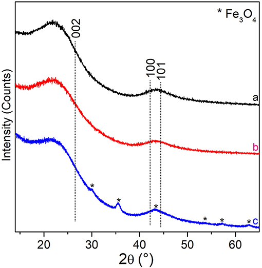
Figure 3. XRD patterns of: PS-co-DVB-pyrolyzed at 800°C for 5 h (black pattern), ZnCl2/PS-co-DVB composite spheres treated at 800°C (red pattern), the carbonized ZnCl2/PS-co-DVB spheres after impregnation with Fe (III) salt and treatment at the same conditions (800°C, 5 h) (blue pattern). XRD plane positions of the (002), (100), and (101) graphite (PDF card #41-1487) and Fe3O4 (PDF card #19-0629, asterisks) are reported.
The N2 adsorption/desorption isotherms and the pore size distributions of the porous spheres, at the different stages of preparation, are shown in Figures 4a–c, while the porosity properties are summarized in Table 1. The PS-co-DVB polymer (Figure 4, a-curve) exhibits a type-I isotherm with a long slope up to the relative pressure of about 0.3 p/p0, which is indicative of a wide distribution of micropores and larger pores. The same kind of isotherm (type-I) is observed for the PS-co-DVB polymer pyrolyzed at 800°C (Figure 4, b-curve), which displays a more rectangular shape, associated with narrow micropores. The relatively low N2 uptake is also indicative of the smaller volume developed, being the pores too small to trap nitrogen. The partial collapsing of the carbon framework, occurred during the thermal process of the pure polymer phase, is confirmed by the reduction in the porosity. The situation is, however, completely different for the ZnCl2-activated samples treated at the same temperature (800°C), before and after impregnation with Fe (III) and the subsequent thermal treatment (Figure 4, c and d-curves, respectively). The ZnCl2-based pyrolyzed carbon materials display a combination of type I and type IV(a) isotherms with steep capillary condensation steps at the relative pressure from about 0.6 and 0.5 p/p0 (ZnCl2-treated and Fe-based ZnCl2-treated samples, c- and d-curves, respectively), indicating the presence of both, well-developed micro- and mesoporosity. The shape of this hysteresis-loop is suggestive of a mixed H4/H1 type, which can be described with a different nature (Thommes et al., 2015), one more common for micro-mesoporous carbons developed by the isotherm at the lower pressure range and one with a more pronounced uptake at the high p/p0, being the behavior associated with the occurrence of more larger and uniform meso/macropores (see steep capillary condensation at the higher relative pressure).
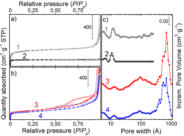
Figure 4. N2-adsorption/desorption isotherms of: (a) the native PS-co-DVB (1-curve) and of the same polymer spheres pyrolyzed at 800°C for 5 h (2-curve); (b) ZnCl2/PS-co-DVB composite spheres treated at 800°C for 5 h (3-curve) and ZnCl2 carbon microspheres after the subsequent impregnation with Fe(NO3)3 and thermal treatment at 800°C for 5 h (4-curve); (c) pore size distributions of the samples.
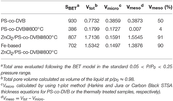
Table 1. Surface area (m2 g−1) and pore volume (cm3 g−1) of the materials at different stages of preparation.
All these findings are in good agreement with the pore size distributions (PSDs) obtained by using the DFT model (Figure 4, right panel). Going into detail, the microporous polymer and carbon spheres, obtained from the direct thermal pyrolysis, show two families of micropores (<7 Å, minor; 9–13 Å range), while the carbonized ZnCl2/PS-co-DVB spheres show a more complex distribution of pores. Besides the two families of micropores (ultramicropores, <6 and 11–15 Å), two additional families of meso- and meso/macropores, very wide in size (30–200 and 300–1,000 Å ranges), are shown. After the subsequent Fe (III) impregnation and thermal treatment at 800°C, no considerable modifications of the PSD are observed. Further differences can be highlighted from the porosity data (BET surface area: SBET; micropore volume: Vmicro; mesopore volume: Vmeso; and total pore volume: Vtot) of the samples, which are summarized in Table 1.
It is noteworthy that the ZnCl2 dispersed in a polymer phase entails a set of reactions (i.e., melting, decomposition, oxidation, reduction to metal and vaporization), thus favoring the formation of an open porosity during the thermal treatment (Cesano et al., 2008b). Furthermore the formation of large mesopores has been observed when ZnCl2 is molecularly dispersed in the termosetting resins (Cesano et al., 2012b). Taking into consideration these previous studies, the fact that ZnCl2 is effective not only in preserving the structural texture from the collapsing during the carbonization step, but also in the activation of the carbon phase under formation, is well-testified by the contribution of the larger pores (meso- and macropores), as well as of the total nitrogen uptake in the Vtot. The following impregnation of the so-obtained carbon microspheres slightly reduces the porosity, but does not affect the pore distributions in large amount.
Inner Structure, Textural, and Vibrational Properties of the Magnetite-Based Carbon Microspheres
A better understanding of the inner structure, in terms of porosity textures of the Fe3O4-based carbon microspheres and of the nanoparticle distribution, has been further obtained by SEM and TEM analyses (Figures 5a–d and Supplementary Figure 2).
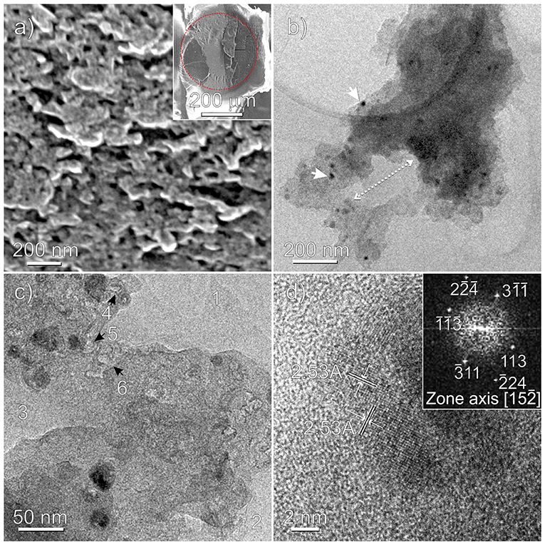
Figure 5. Fe3O4-based ZnCl2/PS-co-DVB microspheres treated at 800°C: HRSEM (a), TEM (b,c), and HRTEM (d) images. A thin slice of a microsphere embedded in the epoxy resin after sectioning the specimen by ultramicrotomy is shown in the inset of (a). The red dotted line evidences the embedded carbonaceous microsphere (darker region) from the epoxy resin (brighter region). Nanoparticles and macropores are highlighted in (b), while 1, 2, 3 and 4, 5, 6 refer to macro- and mesopores in (c), respectively. In the inset of (d) the selected nanoparticle is FFT imaged.
SEM image (Figure 5a) shows a section of the Fe-based carbon microsphere on a microtomed slice (see inset). From this image, pores of irregular shape and distribution with sizes in the 50–100 nm range are clearly shown, but nothing more can be inferred about the Fe phase(s), at the adopted resolution. To gain more insights at the atomic scale, the sample has been TEM and HRTEM imaged, as shown in Figures 5b–d and Supplementary Figure 2. Moving from Figure 5b, besides nanoparticles and aggregates well-dispersed in the matrix with sizes in the ~10–30 nm range, the macroporous nature of the scaffold can be illustrated, where a typical cross-sectional portion of an irregular shaped pore 100 × 200 nm in size is shown. The irregular morphology of the macropores (marked with 1, 2, 3) and of the mesopores about 10 nm in size (marked with 4, 5, 6), which are occurring as irregular voids between agglomerates, is further highlighted in Figure 5c and Supplementary Figure 2. Notice that the pore walls are mostly dominated by curved surfaces. Some more, from the Figures 5c,d regularly shaped nanoparticles and small nanoparticle aggregates, embedded in the carbon amorphous phase, can be better highlighted. In particular, two families of interference fringes, 2.53 Å spaced, can be assigned to the (311) planes of the magnetite nanoparticle encapsulated in the porous carbon matrix (Figure 5d). To this regard, the observed symmetry and the spacings of the bright spots on the FFT (fast Fourier transform) image (inset of Figure 5d) are well-compatible with the orientation along [1 5 -2] zone axis of the Fe3O4 nanoparticle (Supplementary Figure 3). Nonetheless, the presence of other Fe phases (i.e., maghemite) into the sample cannot be ruled out. We shall return on this point by comparing AFM and MFM images of the obtained samples. By now, it is worthy noticing that, together with SEM, the TEM analysis has a relevant role in investigating the porosity of the sample at the nanometric scale, well-supporting the results obtained by gas sorption techniques, which on the other hand provide a systematic statistical analysis. Conversely, due to the distinctive feature of the microscopy approach that is local, and then not statistical, TEM would be ineffective without porosimetry analysis.
Raman spectra of magnetic carbon microspheres, obtained by means of three laser lines (785, 514, and 442 nm), are displayed in Figure 6. All the spectra are dominated by two intense bands, attributed to vibrational modes involving sp2-carbon species with a low sp3-carbon content commonly found in defective nanographitic crystallites (Ferrari and Robertson, 2000; Pimenta et al., 2007; Groppo et al., 2018). The signal around 1,600 cm−1 (G-band, E2g symmetry), resulting from the in-plane bond stretching, is for a fact upward shifted of about 20 cm−1 with respect to the G-band of graphite, thus indicating that the stacking order of the sheets is very low and that the structure is also defective. The second foremost feature around 1,350 cm−1 (D-band, A1g symmetry), that is forbidden in the perfect graphite, becomes active in presence of defects and is linked to the breathing modes of 6-membered carbon rings, being its position influenced by the excitation energy (inset of Figure 6). A D-band dispersion of about 42 cm−1/eV (slope of the linear fitting of D-band positions) is observed by varying the laser excitation energy in the visible range that is indicative of very small graphitic domains (La), which have been calculated to be about 14–15 nm given the proportionality ID/IG ∝ c'(λ) × La2 (where c ~ 0.0055 for λ = 514 nm) (Ferrari and Robertson, 2000) and by using the equation1: La (nm) = 2.4 × 10⁻¹⁰ × (λlaser)4 × (ID/IG)−1 (Pimenta et al., 2007), where the λlaser is in nm, ID and IG are the observed intensities of the D- and G-bands. It is worth noticing that the black color of the sample (Supplementary Figure 5) is responsible for the almost complete light absorption and the low quantity of Fe3O4 (~2.5 wt%) do not allow to recognize the magnetite vibrational fingerprints.
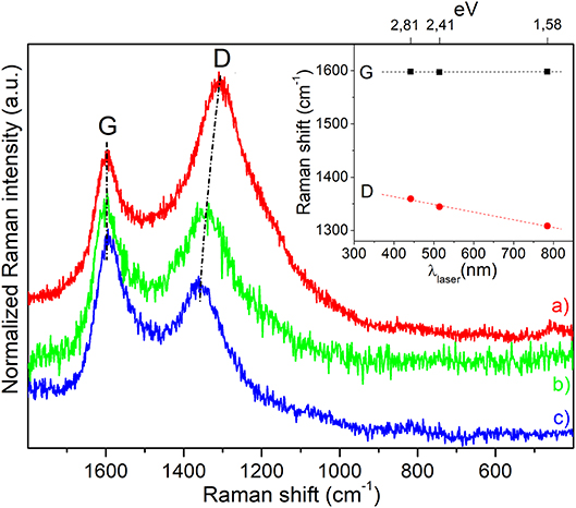
Figure 6. Raman spectra of magnetic carbon microspheres obtained by means of three different exciting laser lines: (a) λ = 785 nm, (b) λ = 514 nm, and (c) λ = 442 nm, respectively. Spectra have been normalized to the G-band and shifted for a better comparison. In the inset the laser energy dependence of D- and G-band positions is illustrated.
Magnetic Properties of the Fe3O4-Based Carbon Microspheres
The combined AFM/MFM investigation of a Fe3O4-based carbon microsphere is reported in Figure 7. Both the AFM topography and the related phase signal images, which are acquired with the standard intermittent contact mode by means of a first-pass acquisition, well-resemble the surface morphology (Figures 7a,b, respectively). The MFM phase shifting of the same region (Figure 7c) is obtained in a second scan above the sample surface to separately measure the magnetic properties after minimizing the capacitive tip-sample coupling (i.e., positive phase shift of non-magnetic interactions) by using a very sharp probe (Krivcov et al., 2018). From the MFM phase image obtained at H = 60 nm, the presence of magnetic material is demonstrated by the negative phase shifting (more extended dark domains), not affected by topography and associated with the attractive interactions between the tip and the sample (Nisticò et al., 2017, 2018).
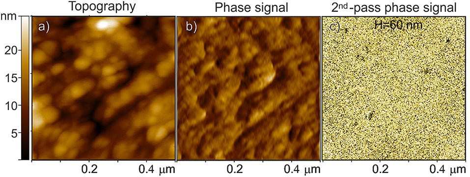
Figure 7. Fe3O4-based carbon microspheres: (a) AFM topography, (b) the related phase signal, and (c) MFM phase shift images at H = 60 nm lift height obtained in a second scan. The phase shift range in (c) is ~ 0.6 m°.
It is worthy noticing that, due to the good dispersion of the magnetic particles within the porous material (see TEM images), only the magnetic nanoparticles closer to the surface are expected to respond to the magnetic interaction with the tip probe.
In conclusion, from either the MFM signal and the TEM images, it results that the nanoparticles are mostly single domain particles or small aggregates of magnetic particles (Butler and Banerjee, 1975), but nothing more can be said about the orientation of their magnetic walls.
To investigate the macroscopic magnetic properties of the Fe3O4-based carbon microspheres, a simple experiment was performed, as illustrated in Figure 8 and in Supplementary Video 1. From these it comes out that iron oxide-based carbon microspheres are affected by a hand-held external magnet.
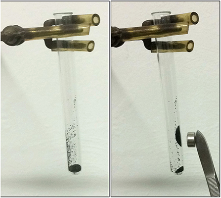
Figure 8. Pictures showing the macroscopic magnetic properties of the Fe3O4-based carbon microspheres.
Optical Properties of the Samples
The absorption spectra, in the 39,500–14,000 cm−1 (or 253–714 nm) UV-visible region, of PS-co-DVB-pyrolyzed at 800°C for 5 h (black curve), of the carbonized ZnCl2/PS-co-DVB spheres after impregnation with Fe (III) salt and treatment at the same conditions (800°C, 5 h) (blue curve), together with the Fe3O4 reference (Sigma Aldrich) (dotted curve) are compared in Figure 9.
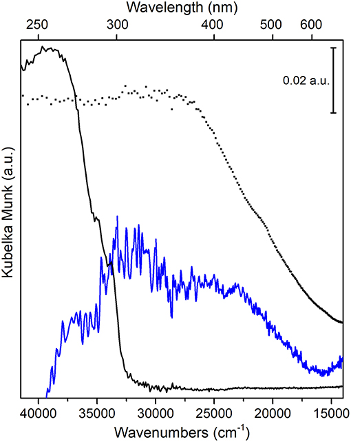
Figure 9. UV-vis spectra of: PS-co-DVB pyrolyzed at 800°C (black curve); carbonized ZnCl2/PS-co-DVB spheres after impregnation with Fe (III) salt and treatment at 800°C (blue curve); Fe3O4, used as a reference (black dotted line).
The intense and wide absorption in the 38,000–33,000 cm−1 range (PS-co-DVB pyrolyzed at 800°C, black curve) can be assigned to the sp2 trigonal π-π* transitions of the amorphous carbon phase, as confirmed by IR results (see Supplementary Figure 4) (Applin et al., 2018). The observed broadening is presumably due to the larger distribution of bonding distances as a consequence of amorphisation effects, which is causing the π-π* band to move to longer wavelengths too. The amorphous nature of the carbon structure for both carbon materials is also well-supported by the observed IR absorption band in the 1,620–1,450 cm−1 range, with a maximum at about 1,570 cm−1 (Supplementary Figure 4, left panel). Such IR band is, for a fact, associated with presence of double-conjugated C vibrational modes (νC = C) in sp2 carbons in presence of defects (i.e., surface terminations, heteroatoms, functional groups, radical species, where there is a change of the dipole moment (in contrast to what observed in graphitic carbon materials, more ordered domains) (Jain et al., 2017; Groppo et al., 2018).
Moving to Fe3O4 doped carbon sample (blue curve) and to Fe3O4 reference (dotted curve), at first a complex and featureless absorption, covering the 36,000–15,000 cm −1 interval, can be observed. Although it is quite difficult to resolve and then to assign the different transitions, according to some authors (He et al., 2005; Yang et al., 2015), we can state that inter-valence charge transfer (IVCT) transitions due to electron transfers from one cation to a neighboring cation in a different oxidation state, dominate the whole spectral region. Concerning Fe3O4 phase, this can be explained with transitions from Fe2+ to Fe3+ bonding and antibonding orbitals (t2g, eg in octahedral sites and t2, e in tetrahedral sites) mediated by O2− ions across the shared edges of adjacent Fe-O polyhedral (Fontijn et al., 1999).
Some more, besides IVCT, also pair excitations resulting from magnetic coupling between neighboring Fe3+ ions together with charge transfers from Fe3+ ions to the adjacent O2− ions contribute to the broad and intense absorption of Fe3O4 nanoparticles in the 25,000–16,000 cm −1 interval. This behavior, typical of systems with two different oxidation states, is indicative of electron delocalization phenomena, which are responsible for the intense color of the material in the visible region as well. A further confirmation of the iron-based oxide formation comes from FTIR spectra, where the intense absorption in the 550–500 cm−1 interval, has been assigned to Fe-O stretching mode of Fe3O4 (Jafari et al., 2014) (Supplementary Figure 4, right panel).
Notice that the intense absorption at about 38,000 cm−1 (black curve), before ascribed to π-π* transitions of sp2 carbon sites inside the amorphous carbon phase, is quite completely eroded, although a redshift inside the complex envelope cannot be ruled out (blue curve). From this, one might infer the occurrence of Fe3O4/carbon interactions at the core-shell interface, as reported by some authors (Jafari et al., 2014).
It is worth noticing that, despite the fact that carbonaceous species are spectrally active in the ultraviolet (UV) region of the spectrum, they have been largely considered only for extra-terrestrial investigations and not for solar system surfaces up to now (Hendrix et al., 2016; Applin et al., 2018).
Summary and Conclusions
The attention on the precise control of the structure/surface has, for the most part, hidden so far the relevance of some properties related to the assembled architectures of the carbon materials. In accordance with the molecular design concept, the rational design of nanostructured porous carbonaceous materials has been adopted. In this contest, we have shown that polymer waste-derived microporous carbon microspheres (SBET ~ 800 m2/g) 100–300 μm in size can be obtained by taking advantage of both, the crosslinked nature and the porous texture of the poly(4-ethylstyrene-co-divinylbenzene) precursor infiltrated by ZnCl2. The ZnCl2 phase, incorporated in the microporous scaffold of the polymer, prevents the collapsing of the pore structure and acts as an activating agent of the carbon phase under formation during the pyrolysis occurring at 800°C, so developing an extended mesoporosity. More interestingly, porous carbon microspheres with magnetic properties have been obtained from the ZnCl2-activated porous carbon spheres after impregnation with Fe nitrate solution and thermal treatment at 800°C. A multi-technique approach has been adopted to characterize more extensively the carbons at the micro/nanoscale. In more detail, the morphology, structure, porous texture and the surface properties of materials have been investigated by several techniques (scanning and transmission electron microscopy, atomic force microscopy, X-ray diffraction, N2-physisorption, diffuse reflectance UV-vis, and infrared spectroscopies). Moreover, magnetic properties have been shown at the nano- and at the macroscale by magnetic force microscopy and simple magnetically guided experiments by permanent magnets. The presented multi-technique methodology aims also to an extensive description of the different characteristics of activated carbons with magnetic properties. The knowledge, tailoring of some intrinsic characteristics (i.e., surface chemistry, enantioselectivity, and other optical properties.) and the combination with some other functionalities (i.e., electrical, magnetic properties), can open a perspective unattainable for the more traditional materials.
Author Contributions
FC, SC, AD, and VB conceived, designed, and performed the experiments and characterizations, analyzed the data. FC, SC, AD, and DS wrote the manuscript. All authors participated in the final editing of the manuscript, read and approved the paper.
Funding
This work was supported by MIUR (Ministero dell'Istruzione, dell'Università e della Ricerca), INSTM Consorzio, and NIS (Nanostructured Interfaces and Surfaces) Inter-Departmental Centre of University of Torino.
Conflict of Interest Statement
The authors declare that the research was conducted in the absence of any commercial or financial relationships that could be construed as a potential conflict of interest.
Acknowledgments
The authors thank Dr. M. C. Valsania for the precious support in TEM experiments. Compagnia di San Paolo and University of Turin, through the program 2013–2015 (Open Access Raman Laboratory), are gratefully acknowledged.
Supplementary Material
The Supplementary Material for this article can be found online at: https://www.frontiersin.org/articles/10.3389/fmats.2019.00084/full#supplementary-material
(TGA plot, additional SEM and TEM images, IR spectra, optical microscope images and a video demonstrating the macroscopic magnetic properties of the Fe3O4-based carbon microspheres).
Footnotes
1. ^Or La (nm) = 560/(Elaser)4 × (ID/IG)−1, where Elaser is given in eV.
References
Anceschi, A., Magnacca, G., Trotta, F., and Zanetti, M. (2017). Preparation and characterization of microporous carbon spheres from high amylose pea maltodextrin. RSC Adv. 7, 36117–36123. doi: 10.1039/C7RA05343F
Applin, D. M., Izawa, M. R. M., Cloutis, E. A., Gillis-Davis, J. J., Pitman, K. M., Roush, T. L., et al. (2018). Ultraviolet spectral reflectance of carbonaceous materials. Icarus 307, 40–82. doi: 10.1016/j.icarus.2018.02.012
Azevedo, D. C. S., Araújo, J. C. S., Bastos-Neto, M., Torres, A. E. B., Jaguaribe, E. F., and Cavalcante, C. L. (2007). Microporous activated carbon prepared from coconut shells using chemical activation with zinc chloride. Microporous Mesoporous Mater. 100, 361–364. doi: 10.1016/j.micromeso.2006.11.024
Benzigar, M. R., Talapaneni, S. N., Joseph, S., Ramadass, K., Singh, G., Scaranto, J., et al. (2018). Recent advances in functionalized micro and mesoporous carbon materials: synthesis and applications. Chem. Soc. Rev. 47, 2680–2721. doi: 10.1039/C7CS00787F
Borchardt, L., Zhu, Q.-L., Casco, M. E., Berger, R., Zhuang, X., Kaskel, S., et al. (2017). Toward a molecular design of porous carbon materials. Mater. Today 20, 592–610. doi: 10.1016/j.mattod.2017.06.002
Butler, R. F., and Banerjee, S. K. (1975). Theoretical single-domain grain size range in magnetite and titanomagnetite. Solid Earth Planets 80, 4049–4058. doi: 10.1029/JB080i029p04049
Calvo-Muñoz, E. M. J., García-Mateos, F., Rosas, J. M., Rodríguez-Mirasol, J., and Cordero, T. (2016). Biomass waste carbon materials as adsorbents for CO2 capture under post-combustion conditions. Front. Mater. 3:23. doi: 10.3389/fmats.2016.00023
Cesano, F., Bertarione, S., Damin, A., Agostini, G., Usseglio, S., Vitillo, J. G., et al. (2008a). Oriented TiO2 nanostructured pillar arrays: synthesis and characterization. Adv. Mater. 20, 3342–3348. doi: 10.1002/adma.200702768
Cesano, F., Pellerej, D., Scarano, D., Ricchiardi, G., and Zecchina, A. (2012a). Radially organized pillars of TiO2 nanoparticles: synthesis, characterization and photocatalytic tests. J. Photochem. Photobiol. A Chem. 242, 51–58. doi: 10.1016/j.jphotochem.2012.05.020
Cesano, F., Rahman, M. M., Bardelli, F., Damin, A., and Scarano, D. (2016). Magnetic hybrid carbon via graphitization of polystyrene-co-divinylbenzene: morphology, structure and adsorption properties. ChemistrySelect 1, 2536–2541. doi: 10.1002/slct.201600278
Cesano, F., Rahman, M. M., Bertarione, S., Vitillo, J. G., Scarano, D., and Zecchina, A. (2012b). Preparation and adsorption properties of activated porous carbons obtained using volatile zinc templating phases. Carbon 50, 2047–2051. doi: 10.1016/j.carbon.2011.12.015
Cesano, F., Scarano, D., Bertarione, S., Bonino, F., Damin, A., Bordiga, S., et al. (2008b). Synthesis of ZnO-carbon composites and imprinted carbon by the pyrolysis of ZnCl2-catalyzed furfuryl alcohol polymers. J. Photochem. Photobiol. A Chem. 196, 143–153. doi: 10.1016/j.jphotochem.2007.07.033
Cheng, G., Zhou, M.-D., and Zheng, S.-Y. (2014). Facile synthesis of magnetic mesoporous hollow carbon microspheres for rapid capture of low-concentration peptides. ACS Appl. Mater. Interfaces 6, 12719–12728. doi: 10.1021/am502712a
Cravanzola, S., Cesano, F., Gaziano, F., and Scarano, D. (2017). Carbon domains on MoS2/TiO2 system via catalytic acetylene oligomerization: synthesis, structure, and surface properties. Front. Chem. 5:91. doi: 10.3389/fchem.2017.00091
Cravanzola, S., Jain, S. M., Cesano, F., Damin, A., and Scarano, D. (2015). Development of a multifunctional TiO2/MWCNT hybrid composite grafted on a stainless steel grating. RSC Adv. 5, 103255–103264. doi: 10.1039/C5RA15003E
Feather, M. S., and Harris, J. F. (1973). Dehydration reactions of carbohydrates. Adv. Carbohyd. Chem. Biochem. 28, 161–224. doi: 10.1016/S0065-2318(08)60383-2
Fenoglio, G., Carlos, L., and Nisticò, R. (2015). One-step synthesis of magnetic chitosan polymer composite films. Appl. Surf. Sci. 345, 175–181. doi: 10.1016/j.apsusc.2015.03.154
Ferrari, A. C., and Robertson, J. (2000). Interpretation of Raman spectra of disordered and amorphous carbon. Phys. Rev. B 61:074414. doi: 10.1103/PhysRevB.61.14095
Fontijn, W. F. J., van der Zaag, P. J., Feiner, L. F., Metselaar, R., and Devillers, M. A. C. (1999). A consistent interpretation of the magneto-optical spectra of spinel type ferrites (invited). J. Appl. Phys. 85, 5100–5105. doi: 10.1063/1.369091
Franzoso, F., Nisticò, R., Cesano, F., Corazzari, I., Turci, F., Scarano, D., et al. (2017). Biowaste-derived substances as a tool for obtaining magnet-sensitive materials for environmental applications in wastewater treatments. Chem. Eng. J. 310, 307–316. doi: 10.1016/j.cej.2016.10.120
Frison, R., Cernuto, G., Cervellino, A., Zaharko, O., Colonna, G. M., Guagliardi, A., et al. (2013). Magnetite-maghemite nanoparticles in the 5–15 nm range: correlating the core-shell composition and the surface structure to the magnetic properties. A total scattering study. Chem. Mater. 25, 4820–4827. doi: 10.1021/cm403360f
Groppo, E., Bonino, F., Cesano, F., Damin, A., and Manzoli, M. (2018). “Raman, IR and INS characterization of functionalized carbon materials,” in Metal-free Functionalized Carbons in Catalysis: Synthesis, Characterization and Applications, eds A. Villa and N. Dimitratos (Cambridge: Royal Society of Chemistry), 103–137.
Hadidi, L., Mahmoud, A., Purkait, T., McDermott, M., and Veinot, J. (2017). Cellulose nanocrystal-derived hollow mesoporous carbon spheres and their application as a metal-free catalyst. Nanotechnology 28:505606. doi: 10.1088/1361-6528/aa95a2
He, Y. P., Miao, Y. M., Li, C. R., Wang, S. Q., Cao, L., Xie, S. S., et al. (2005). Size and structure effect on optical transistions of iron oxide nanocrystals. Phys. Rev. B 71:125411. doi: 10.1103/PhysRevB.71.125411
Hendrix, A. R., Vilas, F., and Li, J. Y. (2016). The UV signature of carbon in the solar system Amanda. Meteor. Planet. Sci. 51, 105–115. doi: 10.1111/maps.12575
Jafari, A., Boustani, K., and Farjami, S. (2014). Effect of carbon-shell on the structural and magnetic properties of Fe3O4 supermagnetic nanoparticles. J. Supercond. Nov. Magn. 7, 187–194. doi: 10.1007/s10948-013-2239-8
Jain, S. M., Cesano, F., Scarano, D., and Edvinsson, T. (2017). Resonance Raman and IR spectroscopy of aligned carbon nanotube arrays with extremely narrow diameters prepared with molecular catalysts on steel substrates. PCCP 19, 30667–30674. doi: 10.1039/C7CP06973A
Kraiwattanawong, K., Sano, N., and Tamon, H. (2011). Low-cost production of mesoporous carbon/carbon composite cryogels. Carbon 49, 3404–3411. doi: 10.1016/j.carbon.2011.04.018
Krivcov, A., Junkers, T., and Möbius, H. (2018). Understanding electrostatic and magnetic forces in magnetic force microscopy:towards singles uperparamagnetic nanoparticle resolution. J. Phys. Commun. 2:075019. doi: 10.1088/2399-6528/aad3a4
Liu, J., Wickramaratne, N. P., Qiao, S. Z., and Jaroniec, M. (2015). Molecular-based design and emerging applications of nanoporous carbon spheres. Nat. Mater. 14, 763–774. doi: 10.1038/nmat4317
Liu, R., Mahurin, S. M., Li, C., Unocic, R. R., Idrobo, J. C., Gao, H., et al. (2011). Dopamine as a carbon source: the controlled synthesis of hollow carbon spheres and yolk-structured carbon nanocomposites. Angew. Chem. Int. Edn. 50, 6799–6802. doi: 10.1002/anie.201102070
Liu, Y., Ren, Z., Wei, Y., Jiang, B., Feng, S., Zhang, L., et al. (2010). Synthesis and applications of graphite carbon sphere with uniformly distributed magnetic Fe3O4 nanoparticles (MGCSs) and MGCS@Ag, MGCS@TiO2. J. Mater. Chem. 20, 4802–4808. doi: 10.1039/b925706c
Lu, F., Huang, C., You, L., Wang, J., and Zhang, Q. (2017). Magnetic hollow carbon microspheres as a reusable adsorbent for rhodamine B removal. RSC Adv. 7, 23255–23264. doi: 10.1039/C7RA03045B
Molina-Sabio, M., and Rodriguez-Reinoso, F. (2004). Role of chemical activation in the development of carbon porosity. Colloids Surfaces A Physicochem. Eng. Aspects 241, 15–25. doi: 10.1016/j.colsurfa.2004.04.007
Nisticò, R., Cesano, F., Franzoso, F., Magnacca, G., Scarano, D., Funes, I. G., et al. (2018). From biowaste to magnet-responsive materials for water remediation from polycyclic aromatic hydrocarbons. Chemosphere 202, 686–693. doi: 10.1016/j.chemosphere.2018.03.153
Nisticò, R., Franzoso, F., Cesano, F., Scarano, D., Magnacca, G., Parolo, M., et al. (2017). Chitosan-derived iron oxide systems for magnetically-guided and efficient water purification processes from polycyclic aromatic hydrocarbons. ACS Sustain. Chem. Eng. 5, 793–801. doi: 10.1021/acssuschemeng.6b02126
Pimenta, M. A., Dresselhaus, G., Dresselhaus, M. S., Cancadoza, L. G., Jorio, A., and Saito, R. (2007). Studying disorder in graphite-based systems by Raman spectroscopy. Phys. Chem. Chem. Phys. 9, 1276–1291. doi: 10.1039/B613962K
Piñeiro-Prado, I., Salinas-Torres, D., Ruiz-Rosas, R., Morallón, E., and Cazorla-Amorós, D. (2016). Design of activated carbon/activated carbon asymmetric capacitors. Front. Mater. 3:16. doi: 10.3389/fmats.2016.00016
Rahman, M. M., Cesano, F., Bardelli, F., Scarano, D., and Zecchina, A. (2010). Hybrid SnO2/carbon composites: from foams to films by playing with the reaction conditions. Catal. Today 150, 84–90. doi: 10.1016/j.cattod.2009.07.063
Rosas, J. M., Berenguer, R., Valero-Romero, M. J., Rodríguez-Mirasol, J., and Cordero, T. (2014). Preparation of different carbon materials by thermochemical conversion of lignin. Front. Mater. 1:29. doi: 10.3389/fmats.2014.00029
Sadakane, M., Horiuchi, T., Kato, N., Sasaki, K., and Ueda, W. (2010). Preparation of three-dimensionally ordered macroporous perovskite-type lanthanum-iron-oxide LaFeO3 with tunable pore diameters: High porosity and photonic property. J. Solid State Chem. 183, 1365–1371. doi: 10.1016/j.jssc.2010.04.012
Sadakane, M., Sasaki, K., Nakamura, H., Yamamoto, T., Ninomiya, W., and Ueda, W. (2012). Important property of polymer spheres for the preparation of three-dimensionally ordered macroporous (3DOM) metal oxides by the ethylene glycol method: the glass-transition temperature. Langmuir 28, 17766–17770. doi: 10.1021/la303921u
Shin, Y., Wang, L.-Q., Bae, I.-T., Arey, B. W., and Exarhos, G. J. (2008). Hydrothermal syntheses of colloidal carbon spheres from cyclodextrins. J. Phys. Chem. C 112, 14236–14240. doi: 10.1021/jp801343y
Signorile, M., Bonino, F., Damin, A., and Bordiga, S. (2018). A novel Raman setup based on magnetic-driven rotation of sample. Top. Catal. 61, 1491–1498. doi: 10.1007/s11244-018-1033-z
Sun, X., and Li, Y. (2005). Ag@C core/shell structured nanoparticles: controlled synthesis, characterization, and assembly. Langmuir 21, 6019–6024. doi: 10.1021/la050193+
Sun, X. M., and Li, Y. D. (2004). Colloidal carbon spheres and their core/shell structures with noble-metal nanoparticles. Angew. Chem. Int. Edn. 43, 597–601. doi: 10.1002/anie.200352386
Thommes, M., Kaneko, K., Neimark, A. V., Olivier, J. P., Rodriguez-Reinoso, F., Rouquerol, J., et al. (2015). Physisorption of gases, with special reference to the evaluation of surface area and pore size distribution (IUPAC Technical Report). Pure Appl. Chem. 87, 1051–1069. doi: 10.1515/pac-2014-1117
Uddin, M. J., Daramola, D. E., Velasquez, E., Dickens, T. J., Yan, J., Hammel, E., et al. (2014). A high efficiency 3D photovoltaic microwire with carbon nanotubes (CNT)-quantum dot (QD) hybrid interface. Phys. Status Solidi (RRL)-Rapid Res. Lett. 8, 898–903. doi: 10.1002/pssr.201409392
Wang, J. G., Liu, H., Sun, H., Hua, W., Wang, H., Liu, X., et al. (2018). One-pot synthesis of nitrogen-doped ordered mesoporous carbon spheres for high-rate and long-cycle life supercapacitors. Carbon 127, 85–92. doi: 10.1016/j.carbon.2017.10.084
Wang, M., Wang, X., Yue, Q., Zhang, Y., Wang, C., Chen, J., et al. (2014). Templated fabrication of core–shell magnetic mesoporous carbon microspheres in 3-dimensional ordered macroporous silicas. Chem. Mater. 26, 3316–3321. doi: 10.1021/cm501186e
Wollbrink, A., Volgmann, K., Koch, J., Kanthasamy, K., Tegenkamp, C., Li, Y., et al. (2016). Amorphous, turbostratic and crystalline carbon membranes with hydrogen selectivity. Carbon 106, 93–105. doi: 10.1016/j.carbon.2016.04.062
Xu, F., Wu, D., Fu, R., and Wei, B. (2017). Design and preparation of porous carbons from conjugated polymer precursors. Mater. Today 20, 629–656. doi: 10.1016/j.mattod.2017.04.026
Yang, D., Pang, X., He, Y., Wang, Y., Chen, G., Wang, W., et al. (2015). Precisely size-tunable magnetic/plasmonic core/shell nanoparticles with controlled optical properties. Angew. Chem. Int. Edn. 54, 12091–12096. doi: 10.1002/anie.201504676
Yang, N., Zhu, S., Zhang, D., and Xu, S. (2008). Synthesis and properties of magnetic Fe3O4-activated carbon nanocomposite particles for dye removal. Mater. Lett. 62, 645–647. doi: 10.1016/j.matlet.2007.06.049
Yi, J., Li, X. P., Hu, S. J., Li, W. S., Zhou, L., Xu, M. Q., et al. (2011). Preparation of hierarchical porous carbon and its rate performance as anode of lithium ion battery. J. Power Sour. 196, 6670–6675. doi: 10.1016/j.jpowsour.2010.12.017
Yin, Y., Zhou, S., Min, C., and Wu, L. (2011). Preparation of rattle-type magnetic mesoporous carbon spheres and their highly efficient adsorption and separation. J. Colloid Interface Sci. 361, 527–533. doi: 10.1016/j.jcis.2011.05.014
Zanetti, M., Anceschi, A., Magnacca, G., Spezzati, G., Caldera, F., Rosi, G. P., et al. (2016). Micro porous carbon spheres from cyclodextrin nanosponges. Microporous Mesoporous Mater. 235 178–184. doi: 10.1016/j.micromeso.2016.08.012
Zhang, H., Yan, Y., and Yang, L. (2010). Preparation of activated carbon from sawdust by zinc chloride activation. Adsorpt. J. Int. Adsorpt. Soc. 16, 161–166. doi: 10.1007/s10450-010-9214-5
Keywords: Fe3O4 nanoparticles, magnetite, amorphous carbon, porous polymers, thermal activation, structure, textural properties, magnetic properties
Citation: Cesano F, Cravanzola S, Brunella V, Damin A and Scarano D (2019) From Polymer to Magnetic Porous Carbon Spheres: Combined Microscopy, Spectroscopy, and Porosity Studies. Front. Mater. 6:84. doi: 10.3389/fmats.2019.00084
Received: 07 October 2018; Accepted: 08 April 2019;
Published: 08 May 2019.
Edited by:
Alan Brian Dalton, University of Sussex, United KingdomReviewed by:
Feng Du, Case Western Reserve University, United StatesDimitrios Gournis, University of Ioannina, Greece
Copyright © 2019 Cesano, Cravanzola, Brunella, Damin and Scarano. This is an open-access article distributed under the terms of the Creative Commons Attribution License (CC BY). The use, distribution or reproduction in other forums is permitted, provided the original author(s) and the copyright owner(s) are credited and that the original publication in this journal is cited, in accordance with accepted academic practice. No use, distribution or reproduction is permitted which does not comply with these terms.
*Correspondence: Federico Cesano, federico.cesano@unito.it
Domenica Scarano, domenica.scarano@unito.it