Model integration methods for hydro-model platform under cloud computing environments
 Ronghua Liu
 Jiahua Wei
 Zhongjing Wang2
  Chi Zhang
- 1China Institute of Water Resources and Hydropower Research, Beijing, China
- 2State Key Laboratory of Hydroscience and Engineering, Department of Hydraulic Engineering, Tsinghua University, Beijing, China
- 3State Key Laboratory of Plateau Ecology and Agriculture, Laboratory of Ecological Protection and High-Quality Development in the Upper Yellow River, School of Water Resources and Electric Power, Qinghai University, Xining, China
- 4TUM School of Engineering and Design, Technical University of Munich, Garching, Germany
Computing platforms providing cloud simulation services have raised new challenges on the model integration. Unlike calls to the model programs (components) in traditional simulation software, here the models should be dynamically integrated in the “plug and play” mode regardless of the differences in model type and developer. To this end two integration methods have been proposed, i.e., coarse-grained EXE integration and interactive integration. In an EXE integration method, the simulation program is directly called and thus only a data conversion interface is needed while rewriting of the model source code is not required. In contrast, an interactive integration method wraps the model components using the standard wrapper with communication interfaces, and therefore, it can communicate and exchange data with the platform in a real time. The first method is suitable for the integration of legacy models, while the second one can control the progress of simulation schemes and facilitate the scheduling of computing resources. Examples of the model integration and platform application have been presented in hydraulics/hydrodynamics to demonstrate the effectiveness of the integration method and the cloud computing platform.
1 Introduction
Real-time sophisticated water resource and hydro-environment management as well as decision-making are relying more and more on the simulation-based multi-scenario analysis, which imposes a challenging requirement on the simulation accuracy, reliability and computing speed. For example, in situations such as the optimal operation of long-distance water pipelines, emergency responses to the water pollution disaster and calibrations of the model parameters, decision-makers and researchers usually would like to select an optimized plan through the comparisons of a large number of optional schemes. On the other hand, it is common to use multiple simulation models to improve the prediction reliability of water management due to the stochastic nature and uncertainty of the fundamental hydrological process. Therefore, large amount of models and heavy computing resources are needed to achieve fast and various multi-scenario analyses. Meanwhile, as some of the computing resources are not always required, it would be more supportive to the decision-makers and economically viable if these could be provided when needed, so as to make the use of computing resources more effective. To satisfy such a requirement, one simulation service platform should have the following two characteristics: 1) it can provide flexible and pay-as-you-go hydro-environment simulation services based on its elastic and use-on-demand computing resources; 2) it can integrate and manage a large amount of different simulation models and thus the end users could have the options to select the most optimal one to achieve their multi-purpose tasks.
Cloud computing is an effective way of providing elastic computing resources. Studies and practices on the water resource management based on the cloud computing originated in 2012. For example, the Environmental Decision Support System (EDSS) used such cloud services as Google Drive and Google Fusion Table and obtained quite promising results Sun, (2013). Bürger et al. (2012) provided hydrological simulation cloud computing services using a platform named ParFlow with high performance clusters. Liu et al. (2013) built a platform “MODFLOWOnAzure” for ground water simulations based on the elastic computing resources of Windows Azure and they also got satisfactory speed up ratios as well. These applications have provided cloud computing services from different aspects or for a certain modeling tool. However, as far as our knowledge is concerned, it is still yet to develop a platform that could dynamically integrate the multiple models and provide simulations (Harris et al., 2021; Zhang et al., 2021; Gu et al., 2022; Gabreil et al., 2022) as a service.
Another difficulty in developing such a platform lies in the robust method of dynamic integrations. However, this is not a brand-new topic, since in literatures many integration methods for single-purpose information management and decision-making systems have been available. Wei et al. (2003) developed a groundwater simulation system based on Map Objects (MO) components and object-oriented technology, where a full integration between the Geographic Information Systems (GIS) and numerical groundwater models was achieved. In MIKE SHE developed by the Danish Hydraulic Institute (DHI, 2004; DHI, 2005), each physical process of the hydrological cycle was modeled and computed individually, and different hydrological cycles were simulated via the data exchange between the multiple models. Each model was wrapped as a component and each sub-process as a module. Based on the river network coding, the digital watershed model (Wang et al., 2007; Li et al., 2009) integrated the runoff, convergence and other simulation processes into a modeling platform, from which the hydrological simulation of the entire basin could be performed. In Peng et al. (2011), a relational database with pre-processing and post-processing modules was used to integrate the Environmental Fluid Dynamics Code (EFDC) Model and the Geographical Information System (GIS) Platform to develop a system with more efficient data processing, organization and analysis. Welsh et al. (2013) developed an integrated river management system, in which different processes such as basin runoff, river network/submergence analysis, water quality, scheduling, irrigation management, and other models were integrated into a simulation and regulation system to evaluate the water quantity and quality in the river basin. The open modeling interface (OpenMI) was used to provide the inter-operations between the model components, such as definition of the exchanged data and drive method. Gregersen et al. (2007) developed a method to integrate platforms and models in a single-process mode, where the single-step boundary definition method was adopted to provide good reference for the model integrations in a cloud platform. Besides, it has been reported by Peckham et al. (2013) and Overeem et al. (2013) that the Community Surface Dynamics Modeling System (CSDMS) also aimed to couple different simulation models with the HPC resources using the modularized method, while Rahman et al. (2004) and David et al. (2013) found that the Object Model System (OMS) and Integrated Customer Management System (ICMS) have the ability to integrate the multiple models which have been developed in an object-oriented language and component-based programming. Most of the above model integration methods use the concept of tight coupling and focus on the integration of models within the platform, which makes it difficult for the models to function independently among the HPC environment. Different with the tight coupling mode, where two programs interoperate by calling each other’s interfaces for data transfer and computation driving, and the same public variables are even used between the two model programs, the loose coupling mode does not call the interfaces directly, but achieve interoperation through third-party platforms. Tight coupling mode is relatively easier to implement as it does not need to consider the interface defined by the platform, and the developer can write the program to realize the data exchange and mutual invocation between the models accordingly. The platform is responsible for defining the standardized interface and calling the model program to achieve data transfer and interoperation, mainly focusing on the definition of the standardized interface and the data exchange and interoperation relationship between the model program, without the need to deeply understand the specific implementation of the model program. The model program does not need to consider the calls and data exchange with other model programs. Compared with tight coupling, the loose coupling mode is more suitable for cloud computing environment, especially for the integration of various complex program call relationship models and large system construction. Platforms such as CSDMS and OMS have achieved the loose coupling and provided useful information on the model integrations as proposed in this paper. However, dynamic integration of models in a cloud computing environment still faces a number of challenging issues, such as the plug-and-play and real-time interactions.
In this paper, two methods of the model integration are proposed, i.e., the EXE integration and interactive integration method. For the legacy models, non-destructive integration to the platform is required so the coarse-grained EXE integration method is proposed. With this method, the source code of the original model does not need to be changed and only a DLL file for data exchange between the model and the platform needs to be developed. On the other hand, for the open-source code models, real-time control on the simulation cases is needed and thus an interactive integration method is preferred. To carry out interactive integration, a standard model wrapper is constructed and the original model code needs to be converted to the model component satisfying the process requirement of the standard model wrapper. In addition, interface files for data exchange between the model component and the platform also need to be developed. With interactive integration, real-time communications between the models and the platform, such as pause, restart and information extraction during the simulation process can be achieved through the named pipes. Both EXE and interactive integration methods use loose coupling, i.e. the models and the platform belong to different processes, which makes the multi-scenario simulation and plug-and-play convenient. Through effective model management, they can be registered, go online or get offline without the need to stop and re-compile the platform. Both integration methods have been implemented on the Hydrological/Hydraulic Modeling Platform (HydroMP) in the work of Liu et al. (2017). It is worth noting that Liu et al. (2017) mainly introduced the architecture, brief technology and application of the cloud computing-based hydrology and hydrodynamic simulation platform HydroMP, while the present paper mainly focuses on the integration technology between the hydrological and hydrodynamic algorithm and the platform, and introduces the details of the integration technology of the model in detail.
This paper will present in details the model integration methods, including the model rewriting, data exchange, inter-process communication and model management. The structure of the paper is as follows: The second section introduces HydroMP and the platform architecture. The third and fourth sections describe the EXE and interactive integration methods, respectively. The fifth section describes the dynamic model management and the sixth section presents examples of the integrated method in hydro-environment applications. Finally the seventh section concludes the paper and discusses future research initiatives. Besides, technical details of the system implementation are provided in a separate Supplementary Appendix File.
2 HydroMP
HydroMP is a hydrological/hydraulic simulation service platform based on the cloud computing, developed to provide elastic and pay-as-you-go water environment simulation service to the decision makers. It is also the platform where the proposed two model integration methods are implemented. HydroMP provides cloud services using the SaaS (Software as a Service) mode (Mell and Grance, 2011) and adopts hybrid cloud architecture. As shown in Figure 1, it includes a HydroMP Center and a number of multiple dynamic HydroMP Servers. The HydroMP Server can be dynamically built into a public or private cloud HPC Cluster and registered in the HydroMP Center. The HydroMP Center deploys the computing resources for each HydroMP Server through a load balancer, thereby providing computing power of theoretically unlimited scalability. In the test environment of present paper, a single HydroMP Server is deployed on the Windows Azure commercial cloud platform to construct elastic HPC clusters through the expansion of virtual machines. Note that HydroMP uses the . Net Framework, which is more compatible with Windows than Linux.
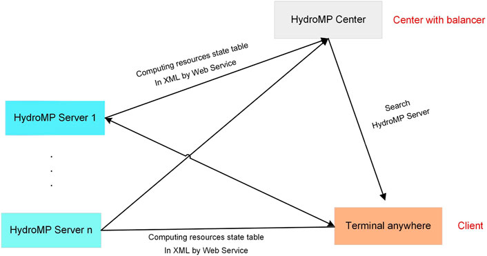
FIGURE 1. The structure of HydroMP platform.
The HydroMP Server performs scenario simulation, model/progress query, result acquisition, and other services through the web service interfaces. Each HydroMP Server integrates a large number of computing resources and hydraulic models. The computing resources are managed through a Windows HPC Server. The HydroMP Server calls the application programming interface (API) provided by the Windows HPC Server to use computing resources. With the proposed model integration methods, HydroMP can dynamically realize the registration, cancellation and information management of the models that meet the requirement of the interface, and the end-users can select appropriate models according to their applicability, accuracy and other indicators. HydroMP is a cloud computing platform for hydrological/hydraulic modeling tools that integrates the computing resources and models to provide scalable model computing capability. Any user terminal can submit a scenario to the cloud and select appropriate models for the specified scenario.
In the structure of HydroMP Sever, platform and computing nodes are distributed in the LAN. When the web service receives simulation requests, the API of the HPC Cluster is called to initiate the simulation processes. Each computing scenario corresponds to one simulation process and all of the simulation processes are randomly assigned to different computing nodes in the cluster. Platform management and scenario simulation can be considered as different processes running on different machines in the LAN. The logical structure of the platform, HPC Cluster and integrated simulation models are shown in Figure 2.
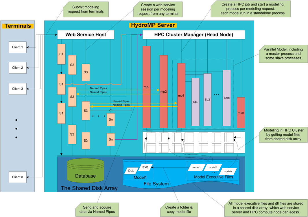
FIGURE 2. Logical hierarchy of the platform and model process in cloud computing environment.
3 EXE integration
Research on a large number of hydraulic models revealed that although these models differ in algorithm and handling of specific problems, the majority of them have the same basic requirements with regard to the system boundary and type of data (Fang and Wang, 2000; DHI, 2004; DHI, 2005; Hu et al., 2009; USACE, 2010; Zhu et al., 2011). For example, all one-dimensional hydrodynamic models of the river network require data on the topology, cross section, boundary condition, simulation parameter and initial conditions. The same calculation conditions across different models make the reuse of the models possible. With the multiple models being integrated in one platform, the users can select the appropriate model by its characteristics and suitability to perform particular tasks and call the interfaces through the Web, so as to enable sharing and reuse of the models. A coarse-grained, non-invasive model integration method (EXE) could be used, where the users do not need to understand the model process or change the model code for model integration.
This method has three characteristics: 1) the original process and code of the model do not need to be changed, and only the input and output file formats should be known. 2) if the integrated model sends output to a file during the simulation, the platform can access the simulation progress in real time using the file size. 3) the input files of the integrated model include all the variables that are parameterized. After the platform starts the simulation process, through real-time monitoring of the output file size, the data exchange can be performed immediately after the scenario simulation finishes. This will meet the real-time requirement of the platform on the model integration. The disadvantage of the method is that, during the running process the platform cannot communicate with the model process directly and thus it cannot control the running process of the model, i.e., the platform cannot pause or resume the simulations once started.
3.1 Method overview
EXE integration focuses on the conversion between the platform and model data structures, calls of the model program by the platform, and the relevant data communications. EXE integration is achieved via the following several steps: 1) by referencing to the Simulation Class provided by HydroMP and implementing the reserved InputFileCreate and OutputFileRead interfaces, the input and output file sets of a particular model are generated. 2) the executable file (EXE file) of the model and the generated input file set are copied, and the System. Diagnostics.Process method is used to run the EXE program. 3) the simulation progress is estimated by using real-time reading of the size of the model output file, thereby implementing the GetComprocess interface. The whole EXE model integration process and its interaction with the platform are shown in Figure 3, which demonstrates the interaction between the platform and DLL and EXE files.
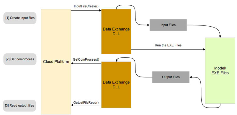
FIGURE 3. Running process of the model in EXE integration mode.
3.2 Interface implementation and file management
The main purpose of the interface InputFileCreate is to generate model input files and start the simulation. The interface GetComprocess estimates the simulation progress by reading the size of the output file. This method applies only to the models running in the simulating-while-outputting mode but not to the models that output the results when the simulation is completed. For the models with constant output step and time intervals, the size of the main output file has a linear relationship with the simulation progress.
The interface OutputfileRead is called once the simulation is completed. Before calling this, it must be determined whether the simulation has been completed or not. Three criteria are used during this process, i.e., simulation progress, file size and any possible error message. The method of reading the output results is opposite to that of generating the input file. The main task is to convert the format of each model output file into the data format required by the platform. After the reading, the file folder generated in Step (1) as illustrated above is deleted.
3.3 Requirements of model integration
The platform scheduler is used to generate the input file and read the output file by calling the unified data conversion interfaces during the running of the model program, and the process management method in the . NET framework is called to initiate the running of the model. Therefore, models that can be integrated using this method must meet certain requirements: 1) data structures and character encoding of the input and output files must be open and clear; and 2) the compiled EXE file must be able to run on Windows platforms. The greatest advantage of EXE integration is that there is no need to rewrite the model source code. However, the platform cannot control or schedule the running of the model, and therefore cannot guarantee real-time access to the model’s progress and results.
4 Interactive integration
4.1 Method overview
In an interactive integration, the model can interact with the platform in real time while running, which enables the features such as model process control, progress acquisition, error messaging, and result acquisition. In HydroMP the platform and model programs run independently on different operating systems in the LAN. Their interactions are thus cross-platform inter-process communication on the same network segment. In general, there are three approaches for the inter-process communications: clipboards, anonymous pipes and named pipes. The clipboard approach is the fastest, but it can only realize communication of the processes running on the same machine. The anonymous pipe approach is used for local communication between the parent and child processes, while the named pipes approach facilitates two-way communications across the networks with the advantages of having simple interface and logical clarity.
Based on the relative locations and dependency relationships of the platform and the model, Named Pipes are used for communication in the proposed interactive model integration. To do this, the named pipes are established between the platform and the model programs, and a set of simple and practical communication rules are defined. The header information on the message string serves as a flag for the identification of communication types, which facilitates rapid parsing of the data at both ends of the pipe once the message is received. A two-layer integration mode is used to speed up the integration and reduce the amount of model code rewriting required. Firstly, a standard wrapper is developed to serve as the middleware between the platform and the models, which can communicate with the platform via named pipes. Secondly, the standard wrapper integrates the models by referencing to the model components and calling the corresponding interfaces. This two-layer integration mode, as shown in Figure 4, reduces the difficulty of integration process since there is no need to consider the communications during the model rewriting. In general, the interactive integration approach includes four steps, namely, rewriting of the model code, implementation of the data conversion interface, generation of the new model executable file using the standard wrapper, and registering the model.
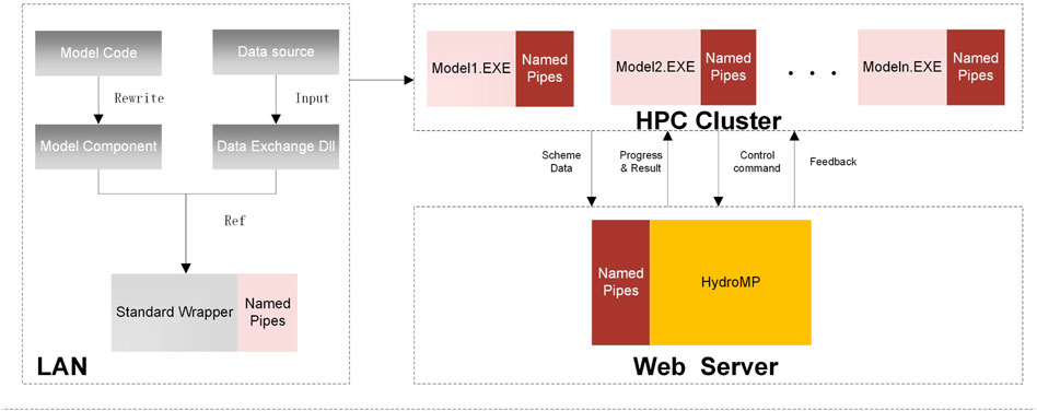
FIGURE 4. Interactive process between platform, model wrapper and DLL files.
4.2 Standard wrapper
The standard wrapper provides a standard program for the communication between the integrated model and the platform, and it communicates with the platform using named pipes. For messages from the platform to the standard wrapper, there are five categories of identifiers, namely, model initialization, initiation of simulation, pausing of simulation, progress acquisition, and result acquisition, which corresponds to the identifiers as Initialize, Start, Pause, Progress, and Result, respectively. There are four categories of messages sent from the standard wrapper to the platform: simulation progress, results of simulation, simulation completion, and pause completion.
The flow chart of the standard wrapper is shown in Figure 5. There are five steps: pipe creation, initialization, data parsing, scenario simulation, and simulation completion. In the initialization step, the wrapper receives the scenario data sent by the platform and obtains a serialized XML byte stream. In the data-parsing step, it desterilizes the byte stream of the scenario into arrays of the wrapper, calls the interface in the data conversion component to generate input file byte streams, and then executes corresponding interfaces in the model component. The scenario simulation step includes the operations such as single-step execution, boundary update, and result acquisition. With the step length parameter, the single-step execution interface performs simulation for a single time step and automatically updates the initialization condition of the model when the simulation is completed. The parameter for the boundary update interface is the boundary condition array in the next time step that includes all the required boundary conditions. The parameter for the single-step result acquisition interface is the time step and the return parameter is a string that needs to be parsed by the data conversion component interface and then attached to the result set array SimulationOut of the wrapper.
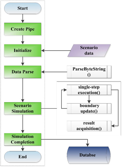
FIGURE 5. Process of the standard model wrapper.
4.3 Methods of rewriting the model
The model wrapper serves as a bridge for communication between the model and the platform. In addition to processing various requests and parsing data sent by the platform, another important role of the model wrapper is to directly integrate the model program (component), call the model interface to execute the simulation, and control the simulation process. In order to integrate a model program into the standard wrapper, the model program must be rewritten and exported in a manner as required by the standard wrapper, forming a model component DLL file. To illustrate the communication between the standard wrapper and the platform and the integration of the model component, the pseudo-code of a standard wrapper is shown in the Supplementary Appendix File.
As shown from the pseudo-code, the standard wrapper needs to call two DLL files: the model component DLL file and the data conversion component DLL file. According to the format of the input files, output files, and single-step boundary data of the model, the data conversion component implements the data conversion interface that converts the data structure of the wrapper into the byte stream format as required by the model component. A new model program is generated by replicating the standard wrapper, referencing the model component DLL file and the data conversion DLL file in this wrapper, and recompiling. After registration, this generated model program can be dynamically called by the platform and there is no need for the platform to recompile and restart.
4.4 Data exchange procedure and method
4.4.1 Exchange of simulation scenario
The scenario string in the wrapper contains three segments of characters—basic information, data set information, and array information, so as to implement data exchange between the wrapper and the platform. Because the format of the input files differ largely between the models, it is not possible to use structured data for the data exchange. A common feature of the input files is that they are a number of text files, although the number of files and data (variables) stored in each file could vary between the models. Based on this, the interactive integration method uses the same number of byte streams as the input files to transmit the scenario string in the wrapper to the model component.
4.4.2 Exchange of result set
The result set of the wrapper includes five different arrays. The first array is of digital type and defines the number of time-series data points; the second array is of length L and defines the type and unit of the output data; the third array defines the serial numbers of the output objects and is an integer array of length M; the fourth array is of length N and defines the time of each data with the format of YYYYMMDDHHMMSS, which is 14 characters long; and the fifth array is of length L*M*N, defining the simulation objects, time points and data types.
4.4.3 Exchange of single-step boundary condition
The single-step boundary conditions, as part of the simulation control, facilitate the data exchange in the scheduler for subsequent integration of the multiple models. The string parameters of single-step boundary function include all the boundary conditions that need to be updated for the model to enter the simulation in the next time step, including the number of boundaries, the serial numbers of boundary objects, the types of boundary conditions, and the numeric values of boundary conditions. For one-dimensional hydrodynamic simulations, it includes the parameters such as Water Level, Discharge, and Lateral Q. The water level—flow discharge relationship is a boundary that does not need to be updated and is thus beyond the scope of single-step boundary conditions.
5 Dynamic model management
The model program generated using either integration approach as described in Sections 3, 4 includes an executable EXE file, a dependent DLL file, and a data conversion DLL file. The platform manages the models by recording the location of the files, model name, model type, model status, and other parameters. Model management includes the operations such as model registration, model cancelation, information editing, and model deletion. All registration information is stored in the model table RegisterModel, the structure of which is shown in Table 1.
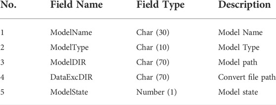
TABLE 1. Structure of model management table.
In the RegisterModel, ModelType consists of 10 characters. The first two specify the type of the model, e.g., hydrological model, hydrodynamic model, or water quality model. The 3rd and 4th characters indicate whether the model is empirical or physical. The 5th and 6th characters denote the dimension of the model, namely, one-dimensional, two-dimensional, or three-dimensional. The 7th and 8th characters denote the type of model integration, namely EXE integration, interactive integration, or OpenMI standard components. The last 9th and 10th characters are the reserved bits.
Model management involves the addition, deletion, modification, and inquiry of the model table. The HydroMP Server provides web service interfaces for the model management, including ModelRegister, ModelEdit, ModelDelete, and ModelUnavailable. When registering a model, the platform administrator needs to store the model name, model path, and data conversion interface file path into the model table.
6 Example of model integration and application
6.1 Example of model integration
Two one-dimensional hydrodynamic models of river networks, CE-QUAL-RIV1 (Dortch et al., 1990) and JPWSPC (Zhu et al., 2011), were used as examples to describe the integration process of different model integration methods. The CE-QUAL-RIV1 model is a 1D hydrodynamic model developed early by the US Army Corps, including a hydraulics module and a pollutant module. It is a legacy model and thus the EXE integration method will be used. The JPWSPC model uses the joint point water stage prediction-correction method to solve the hydrodynamic process of complex river networks. This model will be integrated into the platform using the interactive integration approach.
The input files of the CE-QUAL-RIV1 model include CTL, INP, XSF, BND, and LAT files, representing the control file, main input file, cross section file, boundary file, and lateral inflow file, respectively. The control file gives the names of the subsequent files. The main input file includes the basic river network information, topology, initial conditions, regular cross section, and coefficient of roughness. The cross section file gives the information of irregular cross sections, corresponding to the micro-segments in the INP file through the names of the cross sections. The boundary file gives the time series values of the unsteady upstream and downstream boundaries, which correspond to the river network structure through numbering of the branches. The lateral inflow file documents the unsteady lateral inflow data at different micro-segments. To run the simulation program, one needs to first generate these five files and then double-click the EXE program. The EXE program outputs the results into the OUT file in accordance with the output interval settings defined in the input file while running, until the completion of the simulation. A flow chart of the running process is shown in Figure 6. The CE-QUAL-RIV1 model is integrated by using the coarse-grained, non-invasive integration method, which includes the class referencing, input files Creating interface implementation, Get computing process interface implementation and Output File Reading interface implementation. The details are also shown in Supplementary Appendix SA.
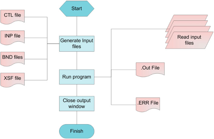
FIGURE 6. Running process of CE-QUAL-RIV1.
The interactive integration approach is used for the integration of JPWSPC model. The original program is rewritten into four functions: Initialize, PerformTimeStep, BndConditionUpdate, and GetStepResult. These functions are then wrapped into the JPWSPC_Model.DLL file. The main function of Initialize is to read the byte streams and parse them into different arrays in the model. The BndConditionUpdate is to update the double-precision boundary data arrays in the model according to the numbering of the boundaries. With PerformTimeStep, one time step of simulation is performed based on the current initialization conditions and boundary conditions to obtain the properties of each micro-segment in this time step. With GetStepResult, the results of single-step simulation of the model are packaged into a byte stream for output.
By comparing the data structure of the wrapper with that of the JPWSPC model, the data structure conversion DLL file JPWSPC_DataExchange.DLL is generated according to the format requirement of the model file, the encoding format of the result byte stream and the sequence format of the boundary condition. Finally, the new executable file JPWSPC-SC. EXE is generated by referencing the JPWSPC_Model.DLL and JPWSPC_DataExchange.DLL files in the standard wrapper. Besides the two models describe above, a number of models including the hydrodynamic model of canal control (Zhang et al., 2007) and the sedimentation model (Zhong et al., 2004) have also been integrated into HydroMP.
6.2 Model application in middle route of South-North water diversion project
In this section the HydroMP with integrated models is applied to the scheduling policy study in the middle route of South-North Water Diversion project (SNWD). The middle route of SNWD is an extra-long water diversion project in China with 1753 cross-sectional structures along the river path, including 61 control gates and 141 diversion gates, which have a total length of 1277 km. A schematic view of the route of SNWD is shown in Figure 7. The operation practice of keeping constant water level in front of the control gate is commonly used to ensure the gate safety. The control and regulation of the main channel are achieved through the coordination of the control gates, diversion gates and outlet gates. The maintenance of constant water level at the control gates becomes much more complicated under the emergency conditions (e.g., a control gate must be closed in a short time in case of the pollution incident). To get an effective control scenario, massive simulations must be concurrently performed and compared to analyze the influence of different regulation factors.
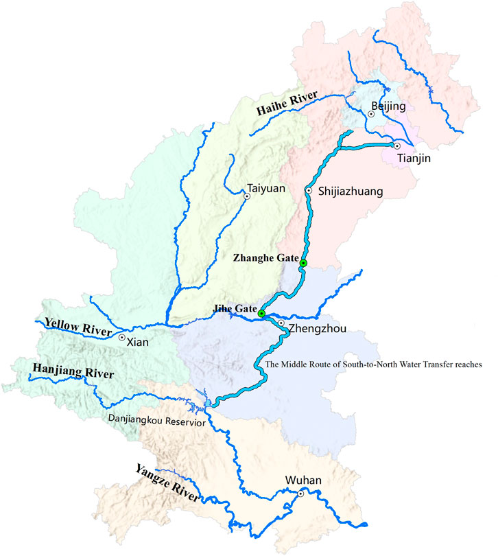
FIGURE 7. The middle route of South-North Water Diversion project.
The canal segment between the Jihe Gate (chainage of 493.138 km) and Zhanghe Gate (chainage of 731.527 km) is taken here as the study segment. Assuming that the upstream canal encounters an emergency, all the control gates in this canal segment must be closed imminently. Different operation scenarios are designed to simulate the response of the flows. The initial conditions are set as follows. The upstream flow has the designed discharge value of 265 m3/s and the downstream water level is set to the designed value of 91.971 m. Two sets of scenarios are designed to analyze the individual influence of the speed and magnitude of gate movement. For each gate movement, five values are specified. With ten control gates and two 1D hydrodynamic models, there are 200 scenarios in total. These scenarios are concurrently submitted to the HydroMP and the simulation results are obtained in a real time. The simulation results show that the range of gate movement is a key factor to affect the flow and water level stability in front of the control gate. Also, it is found that the movement range of different gates should be adjusted according to the distance between the gate and the emergency location. Generally, a gate closer to the emergency location should be set a larger movement range in the beginning phase.
With HydroMP, 11 min were consumed to perform the simulation of 200 scenarios, where 40 virtual machines with 8 cores in Windows Azure were employed to construct the HPC Cluster. The process included scenario group submission, scenario simulation and simulation result acquisition. To verify the efficiency of cloud computing, all the scenarios were simulated sequentially using a single machine and it took nearly 4 h. The speedup ratio of parallel computing is up to nearly 22 times. Note that the parallel efficiency is 0.068. It is found that the main reason for the low parallel efficiency is that the network bandwidth is not enough, which leads to a long waiting time for job submission.
The scalable computing resources provided by HydroMP built in the cloud environment can greatly improve the efficiency of scheduling policy analysis. Moreover, comparison and validation of simulation results using the multiple models are much more convenient because the models integrated into HydroMP can use the same data structure via the data exchange interface in the DLL files. For the end users, both parallel computing and multi-model simulation can be performed on HydroMP platform without extra work.
7 Conclusion
Compared with model integration within a stand-alone system, one difficulty of model integration in cloud computing environments is that the simulation platform and model processes are running on different computers in the LAN of the HPC Cluster. Moreover, the requirements of “plug and play” and universality further increase the difficulty of model integration. According to the characteristics of legacy models and the requirements of multi-model coupling, the EXE integration method and interactive integration method are proposed. The integration processes, requirements on the models, and respective advantages and disadvantages of each method are presented. The details of model rewriting and calling, data exchange, and communications involved in the model integration are described. Model management and classification by the platform are also briefly introduced. The integration processes of two different 1D hydrodynamic models are given as examples to illustrate the practical application of these integration methods. Until now five different hydraulic and sedimentation models, viz. CE-QUAL-RIV1, JPWSPC-SC, JPWSPC-PC, Zhang-Model, THU-SEDIMENTS, have been integrated into HydroMP. These models can be accessed by the end-users anywhere and can be driven by the platform to perform real simulations. The integrated HydroMP framework has the capability of coupling 1D and 2D models, focuses on the boundary condition treatment and date process and transfer. In the interactive integration method, real-time data exchange between different models at a single time step is realized, solving the problem of data transfer and boundary condition treatment. In this case, users can use the inheritance mechanism in the software to write different processing methods.
From the examples of platform application, it was found that the platform can run steadily while concurrently performing 200 scenario simulations using different models and the simulation results can be acquired in real time when the model is integrated in the interactive mode, which demonstrates the effectiveness of the proposed model integration methods and their “plug and play” property. The speedup ratio of about 22 shows the practical efficiency of HydroMP in the cloud computing environment. Meanwhile, it can also be seen that the concurrent simulations of multiple scenarios by using different models can be achieved in a cloud environment. This has significantly increased the simulation efficiency, which has a more prominent speedup effect for the computationally intensive applications.
Future work could include the following aspects. 1) The multi-model coupling interface reserved in the interactive integration method requires further verification. 2) Currently, text files and Named Pipes are used as the message passing channel. Further study should be conducted to use relational databases as the communication media in cloud computing environments. 3) The universality of the proposed model integration methods should be tested on two-dimensional, three-dimensional, and distributed hydrological models. 4) The startup and shutdown of virtual machine should be executed automatically based on the real-time computational needs by calling the scripts by Windows Azure. 5) Simulation interface based on the WebGIS would be more favorable than the currently adopted Terminal + Cloud mode. Furthermore, the proposed model integration methods, although having been designed for cloud computing environments, are also applicable to the stand-alone systems. System designers and developers can choose an appropriate model integration method as per communication cost and complexity of the integrated systems.
Data availability statement
The raw data supporting the conclusion of this article will be made available by the authors, without undue reservation.
Author contributions
RL: investigation, writing—original draft, writing—review and editing; JW: supervision, investigation, writing—review and editing; ZW, BZ, and CZ: investigation, writing—review and editing.
Funding
This work has been sponsored in part by the National Key Technology Research and Development Program of the Ministry of Science and Technology of China (No. 2019YFC1510605), Science and Technology Program of Qinghai (No. 2020-GX-ZL 15) and Program of Joint Research Institute of Tsinghua University—Ningxia Yinchuan for the Internet of Water and Digital Governance (Nos SKL-IOW-2020TC 2004 and SKL-IOW-2022TC2201).
Acknowledgments
We would also like to thank all our sponsors and other members of the HydroMP and Cloud Computing Research Group at the State Key Laboratory of Hydroscience and Engineering.
Conflict of interest
The authors declare that the research was conducted in the absence of any commercial or financial relationships that could be construed as a potential conflict of interest.
Publisher’s note
All claims expressed in this article are solely those of the authors and do not necessarily represent those of their affiliated organizations, or those of the publisher, the editors and the reviewers. Any product that may be evaluated in this article, or claim that may be made by its manufacturer, is not guaranteed or endorsed by the publisher.
Supplementary material
The Supplementary Material for this article can be found online at: https://www.frontiersin.org/articles/10.3389/fenvs.2022.976271/full#supplementary-material
References
Bürger, C. M., Kollet, S., Schumacher, J., and Bösel, D. (2012). Short note: Introduction of a web service for cloud computing with the integrated hydrologic simulation platform parflow. Comput. Geosciences 48, 334–336. doi:10.1016/j.cageo.2012.01.007
David, O., Ascough, J. C., Lloyd, W., Green, T. R., Rojas, K., Leavesley, G. H., et al. (2013). A software engineering perspective on environmental modeling framework design: The object modeling system. Environ. Model. Softw. 39, 201–213. doi:10.1016/j.envsoft.2012.03.006
DHI (2005). Mike ii: A modeling system for rivers and channels reference manual (r). Hørsholm, Denmark: Danish Hydraulic Institute.
Dortch, M., Schneider, T., Martin, J., Zimmerman, M., and Griffin, D. (1990). CE-QUAL-RIV1: A dynamic, one-dimensional (longitudinal) water quality model for streams. User’s Manual. Tech. rep.. Vicksburg, MS (United States): Army Engineer Waterways Experiment Station Vicksburg Ms Environmental Lab.
Fang, H.-W., and Wang, G.-Q. (2000). Three-dimensional mathematical model of suspended-sediment transport. J. Hydraul. Eng. 126, 578–592. doi:10.1061/(asce)0733-9429(2000)126:8(578)
Gregersen, J., Gijsbers, P., and Westen, S. (2007). Openmi: Open modelling interface. J. hydroinformatics 9, 175–191. doi:10.2166/hydro.2007.023
Gu, S., Zheng, W., Wu, H., Chen, C., and Shao, S. (2022). Dualsphysics simulations of spillway hydraulics: A comparison between single-and two-phase modelling approaches. J. Hydraulic Res.. doi:10.1080/00221686.2022.2064343
Gabreil, E., Wu, H., Chen, C., Li, J., Rubinato, M., Zheng, X., et al. (2022). Three-dimensional smoothed particle hydrodynamics modeling of near-shore current flows over rough topographic surface. Front. Mar. Sci. 9. doi:10.3389/fmars.2022.935098
Harris, L., Liang, D., Shao, S., Zhang, T., and Roberts, G. (2021). Mpm simulation of solitary wave run-up on permeable boundaries. Appl. Ocean Res. 111, 102602. doi:10.1016/j.apor.2021.102602
Hu, D., Zhang, H., and Zhong, D. (2009). Properties of the eulerian–Lagrangian method using linear interpolators in a three-dimensional shallow water model using z-level coordinates. Int. J. Comput. Fluid Dyn. 23, 271–284. doi:10.1080/10618560902736475
Li, T., Wang, G., Huang, Y., and Fu, X. (2009). Modeling the process of hillslope soil erosion in the loess plateau. J. Environ. Inf. 14, 1–10. doi:10.3808/jei.200900148
Liu, R., Wei, J., Ren, Y., Liu, Q., Wang, G., Shao, S., et al. (2017). Hydromp–a computing platform for hydrodynamic simulation based on cloud computing. J. Hydroinformatics 19, 953–972. doi:10.2166/hydro.2017.140
Liu, Y., Sun, A. Y., Nelson, K., and Hipke, W. E. (2013). Cloud computing for integrated stochastic groundwater uncertainty analysis. Int. J. Digital Earth 6, 313–337. doi:10.1080/17538947.2012.687778
[Dataset] Mell, P., and Grance, T. (2011). The nist definition of cloud computing draft. special publication 800-145. Available at: http://www.nist.gov/itl/cloud/index.cfm (accessed 08 12, 2022).
Overeem, I., Berlin, M. M., and Syvitski, J. P. (2013). Strategies for integrated modeling: The community surface dynamics modeling system example. Environ. Model. Softw. 39, 314–321. doi:10.1016/j.envsoft.2012.01.012
Peckham, S. D., Hutton, E. W., and Norris, B. (2013). A component-based approach to integrated modeling in the geosciences: The design of csdms. Comput. Geosciences 53, 3–12. doi:10.1016/j.cageo.2012.04.002
Peng, S., Fu, G., Zhao, X., and Moore, B. C. (2011). Integration of environmental fluid dynamics code (efdc) model with geographical information system (gis) platform and its applications. J. Environ. Inf. 17, 75–82. doi:10.3808/jei.201100189
Rahman, J. M., Seaton, S. P., and Cuddy, S. M. (2004). Making frameworks more useable: Using model introspection and metadata to develop model processing tools. Environ. Model. Softw. 19, 275–284. doi:10.1016/s1364-8152(03)00153-1
Sun, A. (2013). Enabling collaborative decision-making in watershed management using cloud-computing services. Environ. Model. Softw. 41, 93–97. doi:10.1016/j.envsoft.2012.11.008
USACE (2010). HEC-RAS river analysis system Hydraulic reference manual. Version 4.1. Tech. rep.. Davis, CA: Hydrologic Engineering Center Davis CA.
Wang, G., Wu, B., and Li, T. (2007). Digital yellow river model. J. Hydro-Environment Res. 1, 1–11. doi:10.1016/j.jher.2007.03.001
Wei, J.-h., Li, C.-j., Wang, G.-q., Shao, J.-l., and Li, S.-l. (2003). Study on the integration of groundwater numeric model and component gis. J. Jilin Univ. Sci. Ed. 33, 534–538. doi:10.1007/BF02873153
Welsh, W. D., Vaze, J., Dutta, D., Rassam, D., Rahman, J. M., Jolly, I. D., et al. (2013). An integrated modelling framework for regulated river systems. Environ. Model. Softw. 39, 81–102. doi:10.1016/j.envsoft.2012.02.022
Zhang, C., Fu, X., and Wang, G.-q. (2007). One-dimensional numerical model for unsteady flows in long-route open channel with complex inner boundary conditions. South-to-North Water Transfers Water Sci. Technol. 5, 16–20.
Zhang, C., Rezavand, M., Zhu, Y., Yu, Y., Wu, D., Zhang, W., et al. (2021). Sphinxsys: An open-source multi-physics and multi-resolution library based on smoothed particle hydrodynamics. Comput. Phys. Commun. 267, 108066. doi:10.1016/j.cpc.2021.108066
Zhong, D.-y., Yang, P., and Zhang, H. (2004). Unsteady one-dimensional numerical model for alluvial rivers with heavy sediment load and its applications. Adv. Water Sci. 15, 706–710.
Keywords: hydromp, model integration, dynamic model management, cloud computing, hydraulics, hydrodynamics
Citation: Liu R, Wei J, Wang Z, Zhang B and Zhang C (2022) Model integration methods for hydro-model platform under cloud computing environments. Front. Environ. Sci. 10:976271. doi: 10.3389/fenvs.2022.976271
Received: 23 June 2022; Accepted: 01 August 2022;
Published: 05 September 2022.
Edited by:
Prashanth Reddy Hanmaiahgari, Indian Institute of Technology Kharagpur, IndiaCopyright © 2022 Liu, Wei, Wang, Zhang and Zhang. This is an open-access article distributed under the terms of the Creative Commons Attribution License (CC BY). The use, distribution or reproduction in other forums is permitted, provided the original author(s) and the copyright owner(s) are credited and that the original publication in this journal is cited, in accordance with accepted academic practice. No use, distribution or reproduction is permitted which does not comply with these terms.
*Correspondence: Jiahua Wei, weijiahua@tsinghua.edu.cn