Closed-Loop Torque and Kinematic Control of a Hybrid Lower-Limb Exoskeleton for Treadmill Walking
 Chen-Hao Chang
 Jonathan Casas
 Steven W. Brose2,3
  Victor H. Duenas
- 1Department of Mechanical and Aerospace Engineering, Syracuse University, Syracuse, NY, United States
- 2Department of Physical Medicine and Rehabilitation, SUNY Upstate Medical University, Syracuse, NY, United States
- 3Spinal Cord Injury and Disabilities Service, Syracuse VA Medical Center, Syracuse, NY, United States
Restoring and improving the ability to walk is a top priority for individuals with movement impairments due to neurological injuries. Powered exoskeletons coupled with functional electrical stimulation (FES), called hybrid exoskeletons, exploit the benefits of activating muscles and robotic assistance for locomotion. In this paper, a cable-driven lower-limb exoskeleton is integrated with FES for treadmill walking at a constant speed. A nonlinear robust controller is used to activate the quadriceps and hamstrings muscle groups via FES to achieve kinematic tracking about the knee joint. Moreover, electric motors adjust the knee joint stiffness throughout the gait cycle using an integral torque feedback controller. For the hip joint, a robust sliding-mode controller is developed to achieve kinematic tracking using electric motors. The human-exoskeleton dynamic model is derived using Lagrangian dynamics and incorporates phase-dependent switching to capture the effects of transitioning from the stance to the swing phase, and vice versa. Moreover, low-level control input switching is used to activate individual muscles and motors to achieve flexion and extension about the hip and knee joints. A Lyapunov-based stability analysis is developed to ensure exponential tracking of the kinematic and torque closed-loop error systems, while guaranteeing that the control input signals remain bounded. The developed controllers were tested in real-time walking experiments on a treadmill in three able-bodied individuals at two gait speeds. The experimental results demonstrate the feasibility of coupling a cable-driven exoskeleton with FES for treadmill walking using a switching-based control strategy and exploiting both kinematic and force feedback.
1 Introduction
The loss of motor and sensory function associated with spinal cord injury (SCI) results in limited mobility, lack of independence, and diminished quality of life (Kirshblum and Lin, 2018; Hornby et al., 2020). Restoring and improving the ability to walk is a top priority for individuals with paralysis, whose locomotion is affected by muscle weakness, impaired postural stability and reduced leg coordination Anderson (2004). Robotic exoskeletons assist individuals with paralysis to improve their gait kinematics, cardiorespiratory and metabolic responses, balance, and mobility (Field-Fote and Roach, 2011; Yang et al., 2015; Ramanujam et al., 2018; Kressler et al., 2018; Sale et al., 2018; Kressler and Domingo, 2019; Hornby et al., 2020; Hong et al., 2020). However, exoskeletal-assisted walking in isolation faces challenges in improving muscle capacity and reinforcing the activation of paralyzed muscles during locomotion (Edgerton et al., 2001; Field-Fote and Roach, 2011). Alternatively, a neuromuscular control approach such as functional electrical stimulation (FES) evokes muscle contractions to replace or assist human volition (Reed, 1997; Peckham and Knutson, 2005). FES applies electrical stimuli across skeletal muscles and can yield benefits such as improved muscle strength, blood flow, bone mineral density, and range of motion (Reed, 1997; Peckham and Knutson, 2005; Doucet et al., 2012). However, isolated control of FES for walking without robotic assistance is challenging due to the nonlinear muscle activation rate and accelerated onset of muscle fatigue (Lynch and Popovic, 2008; Bickel et al., 2011; Downey et al., 2017). A hybrid approach integrating robotic exoskeletons and FES (termed hybrid exoskeletons) Ho et al. (2014); Chang et al. (2015), Chang et al. (2017 SR.) provides the benefits of actively stimulating paralyzed muscles and exploits the robot’s torque reliability to yield repetitive motion. Furthermore, hybrid exoskeletons can contribute to delay the onset of muscle fatigue by reducing the muscle stimulation duty cycle and extend walking endurance. Innovations for the control design and analysis are needed to achieve an effective integration of FES with robotic exoskeletons that interface the human body with different actuation mechanisms.
Hybrid exoskeletons provide postural support, coordinate motion across multiple joints, and apply bursts of electrical stimulation. Several hybrid exoskeletons have incorporated direct joint actuation and implemented closed-loop controllers for the powered machines and FES (Ha et al., 2016; Alibeji et al., 2018a). Hybrid orthoses have been designed to lock and unlock leg joints as a function of the gait cycle to provide upright stability and leg assistance using postural controllers (Kobetic et al., 2009). A hybrid neuroprosthesis (HNP) evaluated a finite state machine controller to coordinate stimulation and exoskeleton inputs for stepping Chang SR. et al. (2017). A HNP with variable-constraint hip mechanisms and neuromuscular stimulation reduced forward lean during walking and improved gait speed To et al. (2014). A hybrid system integrating an exoskeleton to actuate hip and knee joints, and implanted neural stimulation has been developed to increase gait speed in individuals with SCI Nandor et al. (2021). Cooperative control between motor and muscle loops has been developed to minimize the motor torque contribution and maximize the muscle-generated joint torques via surface stimulation (Ha et al., 2016). A position-based controller combining neural networks and classical adaptive control was designed to synchronize a robotic manipulator and FES during assisted leg extension (Alibeji et al., 2017). A closed-loop adaptive control design using iterative learning and neural networks was developed to distribute the control between FES and electric motors to perform sit-to-stand tasks (Molazadeh et al., 2021). Switched control between two modes was developed for a wearable exoskeleton with FES to address nonlinearities and uncertainties in the overall system (Sheng et al., 2021). A controller inspired by the principle of synergies was used to address the problem of actuator redundancy in simulation to control muscles via FES and electric motors (Alibeji et al., 2015). In Alibeji et al. (2018a,b), a muscle synergy-based controller was developed to control muscles and motors accounting for the muscle activation dynamics and the inherent electromechanical delay of muscles. The results in Alibeji et al. (2018a,b) included a rigorous Lyapunov-based stability analysis and experiments with one able-bodied individual and one participant with incomplete SCI. Despite the advances in hybrid exoskeletons, technical innovations are needed to improve the obtained walking speeds and distances (Chang et al., 2020) and yield more natural and compliant interactions for people with varying levels of volition.
Differently from exoskeletons with direct joint motor actuation, soft exoskeletons use wearable garments and Bowden cables to enable human transparent movements for walking and running (Witte et al., 2015, Witte et al., 2017; Collins et al., 2015; Asbeck et al., 2014; Park et al., 2020; Di Lallo et al., 2021). Cable-driven exoskeletons traditionally offload electric motors, gear transmissions, and other components away from the human body. These design features make cable-driven exoskeletons desirable to be interfaced with individuals with varying levels of volition during walking training. Soft wearable exoskeletons and ankle emulators have reduced the metabolic energy consumption during walking by optimizing control parameters in able-bodied individuals and stroke survivors (Zhang et al., 2017; Ding et al., 2018; Witte et al., 2020). Soft exoskeletons have implemented a human-in-the-loop paradigm (Ding et al., 2018; Siviy et al., 2020) demonstrating improvements in walking speed and distance for post-stroke individuals. Cable-driven exoskeletons also hold the potential to be used for function restoration during gait rehabilitation including their combination with FES. Lighter exoskeletons can provide less resistance to muscle effort and could potentially reduce the metabolic costs of walking compared to more rigid exoskeletons Chang S. R. et al. (2017). Integrating the system-level benefits of cable-driven exoskeletons and muscle-driven benefits of FES can provide customized walking behaviors. However, challenges remain to design and evaluate feasible and intuitive control strategies for cable-driven exoskeletons and FES during walking, while developing rigorous control analysis for the multi-joint hybrid system.
A fundamental research question for the development of hybrid exoskeletons is how to allocate or segregate the control design for the powered actuators and muscles (Alibeji et al., 2018a; Alibeji et al., 2018b; Ha et al., 2016). Kinematic tracking has been the primary control objective for rehabilitation devices and machines that combine FES and powered actuation, where the desired trajectories can be tracked by muscles, electric motors (i.e., the machine or robot) or both during walking and cycling (Alibeji et al., 2018b; Duenas et al., 2019; Cousin et al., 2021). Recently, torque tracking objectives have been developed for motorized FES-cycling using admittance-based or impedance-based strategies with a Lyapunov-based analysis (Chang and Duenas, 2019; Duenas et al., 2020; Cousin et al., 2020). Cable-driven exoskeletons allow for the design of force feedback controllers, by including force transducers, as a strategy to adjust the cable tension and influence joint kinematics and kinetics. In particular, muscular and joint stiffness are essential for leg coordination and regulation of posture (Duysens et al., 2000; Nichols, 2002). Stiffness control is motivated for human-machine interaction for its ability to absorb shock, robustness to perturbations, efficiency to release and store energy, and safety (Vanderborght et al., 2013; Grioli et al., 2015; Keemink et al., 2018). Stiffness control has been widely used in industrial manufacturing machines, grasping for robotic hands Garate et al. (2018), upper-limb exoskeletons (Li et al., 2018), ankle actuators (Moltedo et al., 2019), and surgical manipulators (Mahvash and Dupont, 2011). Stiffness controllers traditionally use impedance-based models to generate interaction torques based on changes in the joint kinematics. Gait training was performed using an admittance controller in a robot that converts desired assistance to joint trajectories and stiffness profiles (Meuleman et al., 2016). A hybrid FES-exoskeleton cooperative strategy exploited a torque field with stiffness and damping for the motor control, while kinematic controllers were designed for the muscles (Del-Ama et al., 2014). The motivation in this paper is to exploit the ability of the cable-driven exoskeleton to adjust the joint stiffness and design FES controllers for muscles during walking.
In this paper, kinematic and torque tracking controllers are designed to activate the electric motors of a lower-limb cable-driven exoskeleton and muscles via FES to achieve treadmill walking at a constant speed. The hybrid exoskeleton and human are modeled as a four-link bipedal walking system with state-dependent switched dynamics to describe the gait phase transitions from stance phase to swing phase, and vice versa. The leg dynamics are modeled as a switched system to characterize the pendulum dynamics within the swing phase and the inverted pendulum dynamics within the stance phase, and their ongoing transitions during walking. The quadriceps and hamstrings muscle groups are electrically stimulated using a nonlinear robust kinematic feedback controller to guide the knee joints through their desired joint angles, while the electric motors adjust the cable tension to achieve a desired torque using a stable stiffness model. The electric motors provide torque assistance about the hip joints to track the desired hip joint angles. The bipedal walking dynamics include low-level switching to determine the active muscles and electric motors to achieve flexion and extension motion for the knee and hip joints. A Lyapunov-based approach is developed to ensure exponential tracking of the kinematic and torque closed-loop systems. Experimental results in three able-bodied individuals are presented describing the feasibility of the control methods. A discussion on the obtained experimental results and the future work are described.
2 Dynamic Model
2.1 Human-Exoskeleton Dynamics
The hybrid exoskeleton and a human can be modeled as a four-link bipedal walking system in the sagittal plane with a switching Euler-Lagrange model as
where the subscript
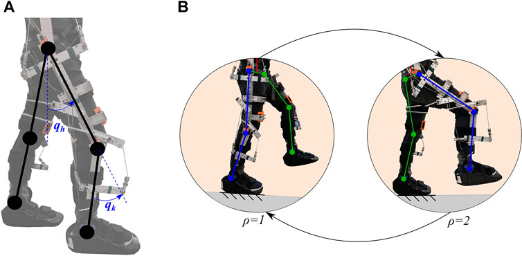
FIGURE 1. Schematic of the human-exoskeleton system with switching dynamics. (A) The knee joint angle qk and hip joint angle qh of the right leg are depicted in an initial standing position. (B) The switching dynamics are illustrated using the stance leg as reference (i.e., support leg). The subsystem ρ = 1 denotes when the right leg is in the stance phase and the left leg is in the swing phase. The subsystem ρ = 2 denotes when the left leg is in the stance phase and the right leg is the swing phase.
The torque inputs in Eq. 1 include

FIGURE 2. Schematic of the hybrid exoskeleton actuation for walking. (A) The actuation of the cable-driven exoskeleton is illustrated, where a couple of flexor and extensor cables on each joint are tensioned to provide torque about the joints. (B) The FES applied to the quadriceps (quad) and hamstrings (ham) muscle groups to generate torque about the knee joint is depicted.
2.2 Actuator Input Switching
The lower-limb hybrid exoskeleton actuates joints using electric motors that drive customized cable-driven mechanisms combined with FES applied to the muscles. The allocation of the control commands to a subset of actuators (i.e., motors and muscles) is needed to yield adequate leg coordination. Hence, a two-layer scheme is designed and illustrated in Figure 3. The upper layer is the exoskeleton joint control loop, where the desired tracking objectives (i.e., kinematic and stiffness tracking) are achieved by the designed muscle and motor control inputs um, ue, respectively, subsequently defined. The lower layer allocates the muscle and motor inputs um, ue, computed in the upper layer, to individual muscles and motors. Such allocation is achieved by means of the switching signals σm, σe that activate muscles and motors, respectively, to achieve flexion or extension. Within the lower layer for the motors, a synchronization controller is designed to prevent a slacking behavior in the cables and improve the response time of the motors. Figure 3 depicts the block diagram of the upper and lower control layers. The design and stability analysis of the synchronization motor controller is described in Chang et al. (2021). This controller is implemented for each pair of motors that actuate any given joint. During the implementation of the synchronization motor controller one motor (lead motor) receives the upper layer input ue, whereas the other motor (follower motor) receives the synchronization control input. This synchronization control input is designed to track a desired motor angular position to maintain appropriate tension and reduce cable slackness (Chang et al., 2021). The torque produced by motors and muscles can be defined as
where the subscript
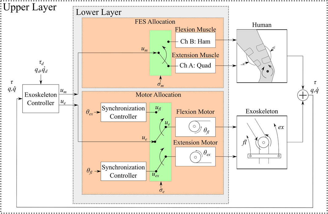
FIGURE 3. Block diagram of the two-layer control scheme. The upper layer is the joint feedback loop to generate the muscle and motor control inputs um and ue, respectively. The muscle and motor inputs can exploit kinematic or torque feedback. The lower layer allocates the upper layer control inputs um, ue to individual muscles and motors. The allocation is dictated by the switching signals σm, σe to apply FES and electric currents, respectively. Within the lower motor layer, a synchronization controller is designed to maintain suitable cable tension and avoid cable slackness.
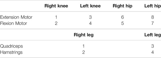
TABLE 1. Flexion and extension motor indices for right and left hip and knee joints (top). Quadriceps and hamstrings muscles indices for right and left leg (bottom).
The following properties are exploited in the subsequent control design and stability analysis.
Property 1 The inertia matrix Mρ(q) is positive definite and symmetric, and satisfies the inequalities
Property 2 The inverse of the inertia matrix Mρ(q) is bounded as
Property 3
Property 4
Property 5
Property 6 The lumped kinematic switching control effectiveness is a diagonal matrix and is bounded as
Property 7 The lumped stiffness switching control effectiveness is a diagonal matrix and is bounded as
Assumption 1
3 Control Development
The control design is segregated for the stance and swing phases of walking. To absorb the foot impact and guarantee trunk support during early stance, the stiffness in the knee joint is increased and knee extensor activity is modulated (Neptune et al., 2008), which ultimately contributes to enable body propulsion and initiate swing. On the other hand, during the swing phase, leg stiffness is reduced to increase compliance and allow smooth knee joint kinematics and prepare for heel strike (i.e., contact with the ground). Hence, the knee joint stiffness contributes for shaping the leg dynamics along with the hip joint that assist body propulsion and preserve the rhythmic walking motion (Perry, 1992; Duysens et al., 2000). Inspired by such joint behaviors, a multiple control objective is developed in this paper to adjust the joint stiffness and kinematics on both phases, while ensuring a stable rhythmic walking motion.
Two control objectives are developed as depicted in Figure 4. The first objective is to design kinematic controllers (κ) to track knee and hip joint trajectories. A pair of electric motors achieve the kinematic tracking objective for the hip joints, whereas FES applied to the quadriceps and hamstrings achieve kinematic tracking for the knee joints. The second objective is to design a knee joint stiffness controller (s) throughout the gait cycle using the electric motors that actuate the knee joints. Since the electric motors and FES cooperate to achieve both control objectives, the control effectiveness matrices can be segregated for the kinematic and stiffness control objectives as depicted in Figure 4C, where the lumped effectiveness Bκ and Bs are defined for the kinematic and stiffness control loops, respectively. The control design for each objective is developed in the subsequent subsections. A robust control technique is applied to track the desired angle trajectories and a torque controller is designed to track the desired knee stiffness on both gait phases.
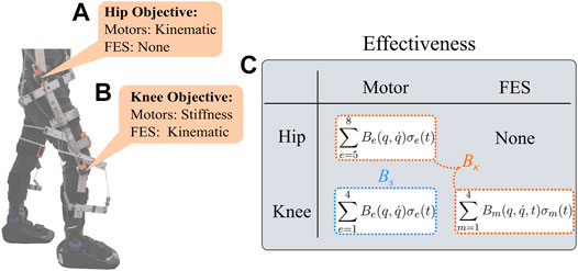
FIGURE 4. Schematic of the kinematic (κ) and stiffness (s) control tracking objectives. (A) The hip joint is actuated only by the electric motors to achieve kinematic tracking (i.e., no FES is applied). (B) The knee joint is controlled to achieve both control objectives: electric motors track the stiffness objective and the muscles track the kinematic objective. (C) The table shows the control effectiveness matrices associated with the kinematic and stiffness control objective, Bκ and Bs, respectively.
3.1 Kinematic Control
The human-exoskeleton dynamics with motor and muscle torque inputs in Eq. 1 can be expressed in terms of the kinematic control objective as
where the hip motors dedicated for kinematic tracking are represented by the motor index e = {5, 6, 7, 8} as described in Table 1.
The measurable angular position tracking error
where
where the auxiliary signal
By using Properties 2–5, Assumption 1, Eqs 6, 7, the auxiliary signal in Eq. 9 can be upper bounded as
where
where
Remark 1 To implement Eq. 11, us is initialized at zero (i.e., [0,0]T), such that
3.2 Stiffness Control
The stiffness control objective is to track a desired torque for the knee joints. Hence, the knee-shank dynamics in Eq. 1 can expressed as
where the subscript k refers to the knee-joint dynamics,
where the effectiveness dimension has been reduced from 4 × 4 to 2 ×2 since the stiffness control objective is developed only for the knee joints. Hence, the torque due to the stiffness controller τs about the hip joints is zero (i.e.,
To generate the desired torque, a stiffness model is designed as
where
An integral-like torque tracking error
where τk ≜ τκk + τsk is the measurable torque applied about the knee joints. Taking the derivative of Eq. 16, setting the initial conditions to zero, and substituting the measurable torque inputs from the right-hand side in Eqs 13, 15 yields
where
where
3.3 Actuator Control Inputs
The kinematic and stiffness control tracking objectives combine muscle and motor inputs. Hence, the relationship between the implementable control inputs ue and um (depicted in Figure 3) and the designed uκ and us can be defined as
where
4 Stability Analysis
The stability of the kinematic and stiffness controllers that activate the electric motors and muscles can be examined independently through the following two theorems. Theorem 1 shows that given the closed-loop kinematic error system in Eq. 12, the joint kinematic controller in Eq. 11 achieves exponential tracking. Theorem 2 shows that given the closed-loop stiffness error system in Eq. 19, the torque controller in Eq. 18 achieves exponential tracking. All the control inputs and error signals are shown to be bounded.
Theorem 1 Given the closed-loop error system in Eq. 12, the controller in Eq. 11 ensures exponential tracking in the sense that
provided the following sufficient gain conditions are satisfied
Proof. Let
which satisfies the following inequalities
where
The generalized time derivative of (24) can be upper bounded using Property 6 as
Provided the gain conditions in Eq. 23 are satisfied, the inequality in Eq. 27 can be further upper bounded as
where
where
provided the following sufficient gain conditions are satisfied
Proof. Let
Let es(t) be a Filippov solution to the differential inclusion
An upper bound for the previous expression can be obtained by using Property 7 and substituting the upper bound of K(t) to yield
Provided the gain conditions in Eq. 31 are satisfied, the inequality in Eq. 34 can be further upper bounded as
where
5 Experiment Results
Experiments are provided to demonstrate the performance of the kinematic and stiffness controllers developed in Eqs 11, 18 to control the knee and hip joints. The control inputs are commanded as stimulation intensities (i.e., pulse width control) to activate the quadriceps and hamstring muscle groups and as currents to the electric motors. Three able-bodied individuals (two males aged 29 years and one female aged 29 years) participated in the exoskeleton protocol at Syracuse University. Written informed consent was obtained from each participant, as approved by the Institutional Review Board at Syracuse University. The participants were instructed to avoid voluntarily contributing to the treadmill walking task. To mitigate the influence of the ankle joint for propulsion, an orthotic boot is used to mechanically lock the ankle and provide foot cushion. The individuals could not see the walking performance plots during the experiments.
Testing were performed using a customized exoskeleton designed for fitting different body sizes and maintaining alignment with the user’s joints. Figure 5 illustrates the exoskeleton testbed. The actuator unit includes brushless 24 VDC electric motors (Maxon) to adjust the torque applied by the cable-driven mechanisms. Optical encoders (US Digital) were mounted at each joint to measure the joint angle and load-cells (OMEGA) were installed in series with the cables to measure cable tension. The controllers were implemented on a desktop computer (Windows 10 OS) running a real-time target (QUARC 2.6, Quanser) via MATLAB/Simulink 2018a (MathWorks Inc) with a sample rate of 1 kHz. The Quanser QPIDe DAQ board was used to read the encoders and cable tensions, and control the servo motor drivers (Maxon) operating in current-controlled mode. The Quanser Q8 USB board was used to read the encoders mounted on motors. A current-controlled stimulator (RehaStim, Hasomed GmbH) delivered biphasic, symmetric, rectangular pulses to the participant’s quadriceps and hamstring muscle groups. Self-adhesive PALS® electrodes (3″ by 5″)1 were placed on each muscle group in both legs. The stimulation current amplitude and stimulation frequency were fixed at 80 mA and 60 Hz, respectively. A treadmill (Nordic Track) equipped with an encoder (US Digital) to measure the belt’s angular displacement was used for walking at two constant speeds: 0.5 and 0.8 mph. The speed of the treadmill was closed-loop controlled using a sliding-mode controller and implemented in a motor driver in current-control mode (Advanced Motion Controls)2. As safety measures, the participant had access to an emergency stop button and software stop conditions were implemented to limit the amount of motor currents to comply with the hardware limits and prevent large current transients from being applied to the participant, and muscle stimulation intensities to prevent uncomfortable stimulation intensities. Mechanical stops were designed to avoid moving the legs through unsafe joint angles, and the participants wear a safety harness connected to a portable track system to prevent falling without restricting the motion.
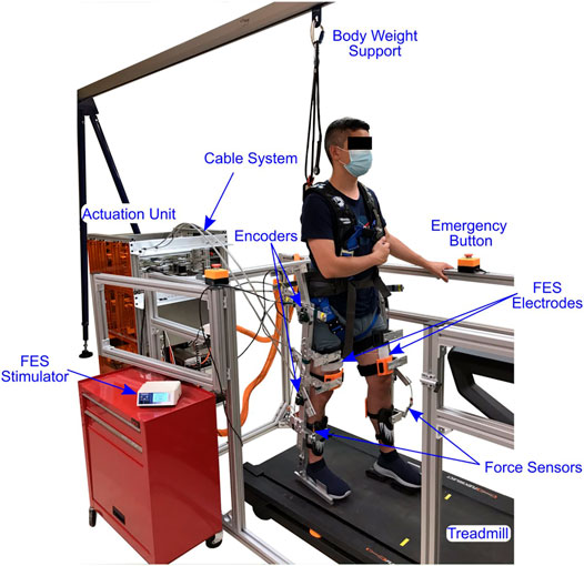
FIGURE 5. The exoskeleton testbed used for treadmill walking. The exoskeleton uses cables to apply torque at each joint using electric motors installed in the actuation unit. Surface FES is applied on the quadriceps and hamstrings muscle groups. Additional components of the walking system are labeled in the image.
A walking pretrial was performed wearing the exoskeleton in passive mode (i.e., the exoskeleton did not provide assistance to the participant) to record walking data for each participant to generate the smooth desired kinematic trajectories
Table 2 summarizes the root-mean-squared (RMS) and average of the kinematic and stiffness tracking errors for all subjects with the two tested gait speeds. The experimental results were analyzed after the sixth gait cycle from the point at which the treadmill reached the desired steady-state gait speed. During the first five gait cycles the participants began stepping on the treadmill to smoothly reach the steady state constant walking speed. The kinematic tracking performance for two participants at different gait speeds is illustrated in Figures 6, 7, where the desired joint trajectories are depicted in blue and the actual joint angles are depicted in red. The kinematic joint trajectories corresponding to each gait cycle during a complete treadmill walking experiment are depicted as a function of gait cycle percentage in Figure 8.
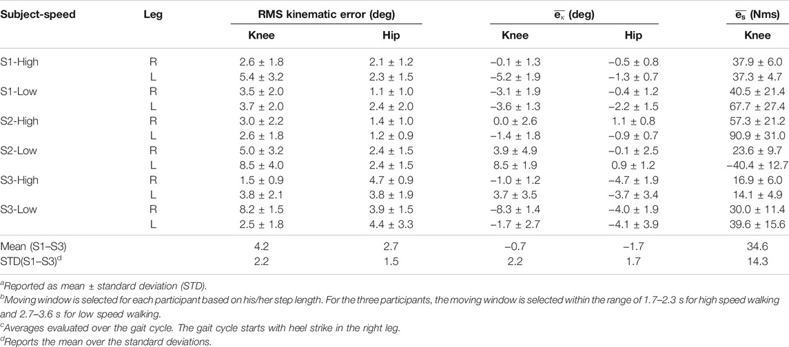
TABLE 2. Tracking results for each participant at high (0.8 mph) and low (0.5 mph) treadmill walking speedsa: RMS kinematic tracking error (moving window in seconds to complete a gait cycle)b, average of kinematic tracking error
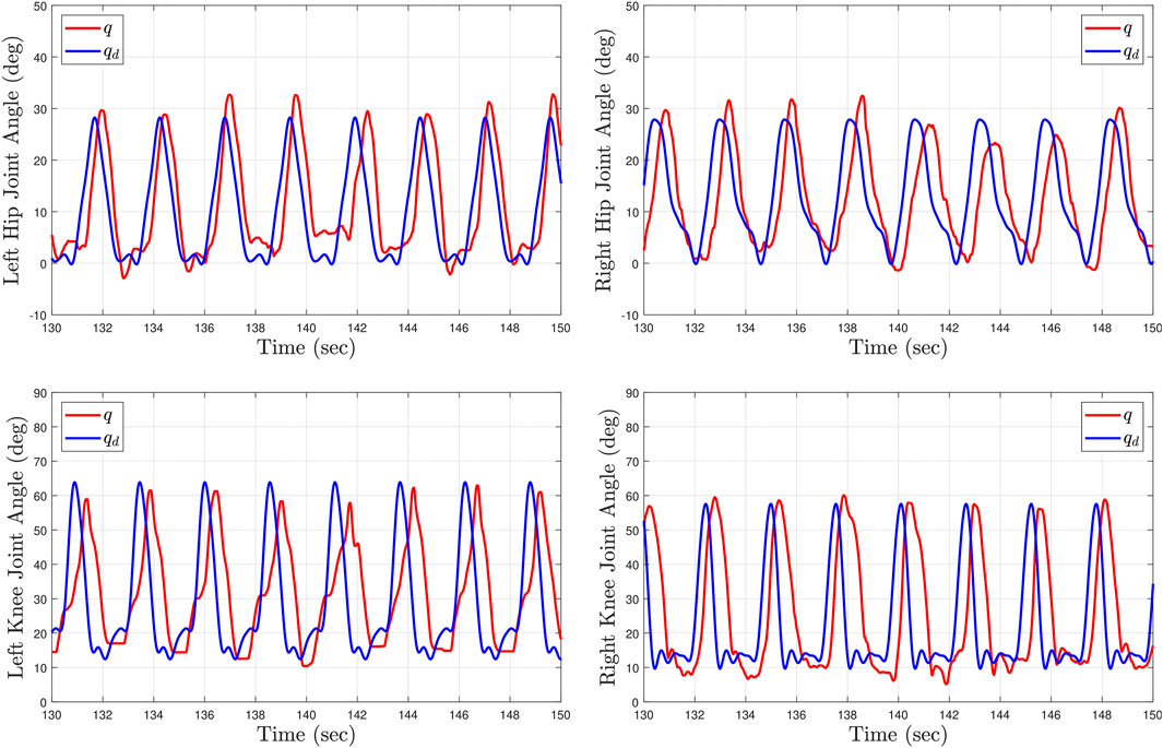
FIGURE 6. Kinematic tracking performance for Subject 2 (S2) after 2 minutes of treadmill walking at high speed (0.8 mph). The top plots depict the left and right hip joint kinematics. The bottom plots depict the left and right knee joint kinematics. The blue curves illustrate the desired kinematic trajectories and the red curves show the actual joint angles.
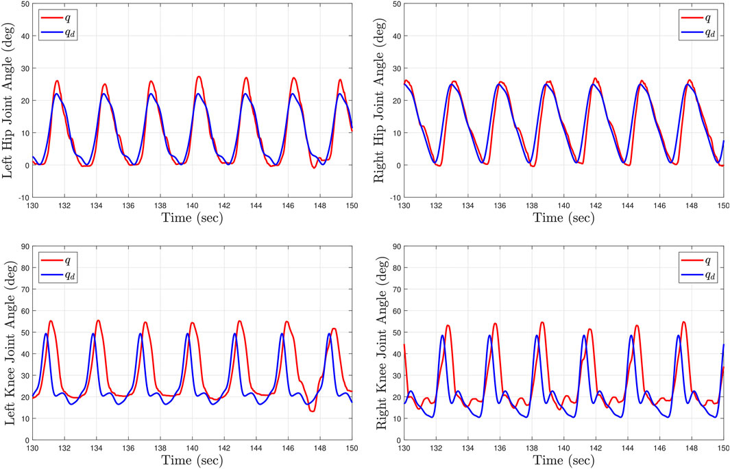
FIGURE 7. Kinematic tracking performance for Subject 1 (S1) after 2 minutes of treadmill walking at low speed (0.5 mph). The top plots depict the left and right hip joint kinematics. The bottom plots depict the left and right knee joint kinematics. The blue curves illustrate the desired kinematic trajectories and the red curves show the actual joint angles.
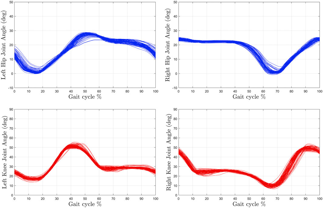
FIGURE 8. The kinematic joint trajectories corresponding to each gait cycle during the treadmill walking experiment at high speed (0.8 mph) for Subject 1 (S1).
The control inputs are presented in Figure 9, the quadriceps and hamstrings muscle stimulation inputs um for both legs are displayed at the top, whereas the electric motor input commands ue are depicted at the bottom. The muscle input switching is observed through the activation of hams and quads to achieve flexion and extension, respectively. Similarly, the motor commands are switching between the upper layer command um and the lower layer synchronization control commands ufl and uex as depicted in Figure 3.
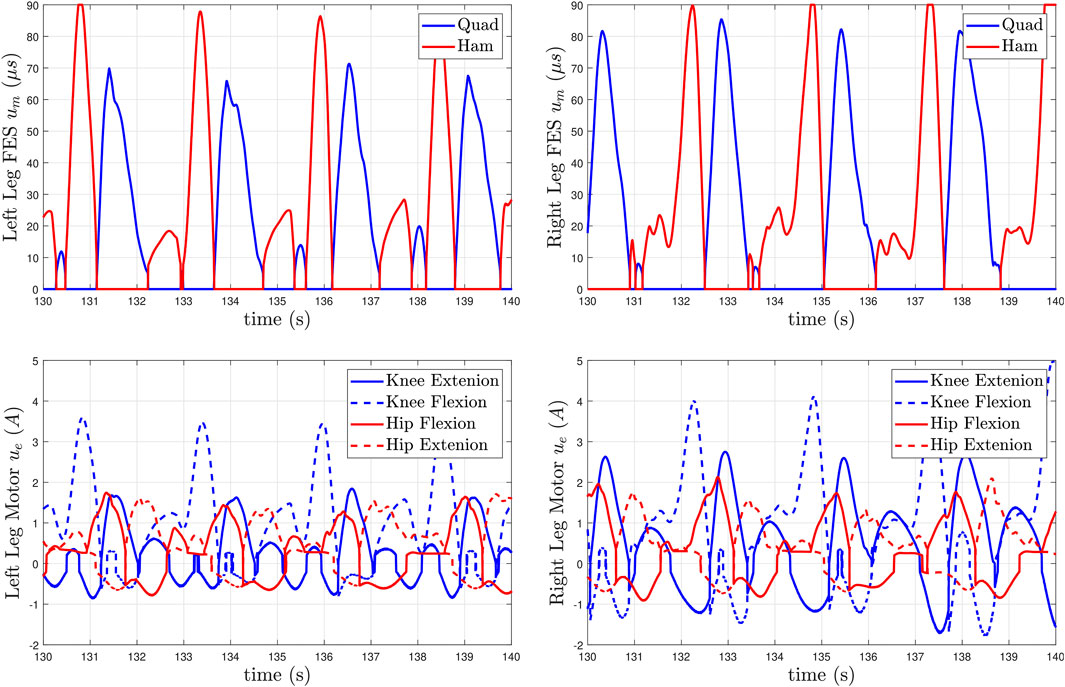
FIGURE 9. Distribution of the muscle and motor control inputs for Subject 2 (S2) during the high speed walking trial (0.8 mph). The top plots depict the pulse widths generated by um and applied to the quadriceps and hamstrings muscle groups for the left and right legs after 2 minutes of treadmill walking. The bottom plots show the motor currents generated by ue and applied to the motors that actuate the knee and hip joints of the left and right legs.
The stiffness tracking errors for the left and right knee joints are presented in Figure 10. The stiffness errors in Figure 10 are quantified using a moving time interval window of 1.99 s, which is selected based on the walking speed and step length of the participant. Both integral stiffness error signals remain bounded during the experiment. Figure 11 depicts the computed foot trajectories in the sagittal plane for the two gait speeds, which further illustrates the influence of the developed controllers and gait speed on the participant’s walking pattern.

FIGURE 10. Stiffness tracking performance during treadmill walking at high gait speed (0.8 mph) for Subject 1 (S1). The stiffness tracking performance is depicted in blue and red for the right and left knee joints, respectively. The data is presented with a moving time interval window of 1.99 s, which is the time in seconds to complete a gait cycle.
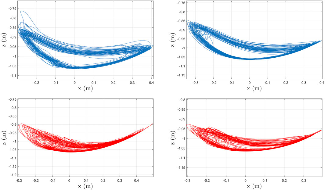
FIGURE 11. Foot trajectories in the sagittal plane (i.e., the foot path in the x-z plane) at high (top) and slow (bottom) speeds for Subject 2 (S2). The plots in the left column correspond to the left leg and plots in the right column correspond to the right leg. The trajectories are computed using collected joint angles, where the origin corresponds to the trunk position.
6 Discussion
The experimental results demonstrate the feasibility of the controllers developed in Eqs 11, 18 to activate lower-limb muscles via FES and provide torque assistance about the knee and hip joints. The designed controllers exploited kinematic and torque feedback to achieve treadmill walking at a constant speed. By adjusting the tuning of the stiffness controller, the exoskeleton provides higher or lower leg compliance, which directly influences the joint kinematics. In addition, adjusting the tuning of the muscle kinematic controllers can customize the stimulation intensities applied to the quadriceps and hamstrings muscle groups. Therefore, coupling kinematic and stiffness controllers for FES and electric motors can influence each individual’s gait kinematics and foot trajectories across different walking speeds as illustrated in Figure 8 and Figure 11. As depicted in Figure 8, the developed controllers achieved repeatable and consistent kinematic joint trajectories as a function of the gait cycle for participant S1. Moreover, consistent joint kinematic patterns were obtained across all participants for both walking speeds, which are described with a group average of the joint angle standard deviations: ± 5.85° for the right knee, ± 5.03° for the right hip, ± 8.57° for the left knee, and ±5.88° for the left hip. Similarly, Figure 11 denotes the foot trajectories in the sagittal plane, which are computed based on joint kinematics. The foot path is another indirect metric of gait consistency, which could be further used to quantify human performance or design alternate control methods. The integration of FES and cable-driven exoskeletons holds the potential to customize the human interaction to restore or improve function in individuals with movement disorders by achieving repetitive and coordinated walking.
The results in this study align qualitatively with previously published results for exoskeletons that include FES to activate lower-limb muscles. However, the differences in the control designs and experimental test beds pose challenges to directly compare the obtained results in this study with previous studies on hybrid exoskeletons. In Alibeji et al. (2018a,b) a hybrid neuroprosthesis (i.e., a powered exoskeleton with surface FES) was tested in one able-bodied individual and one participant with SCI. The performance of the designed muscle and motor controllers was demonstrated during overground walking assisted by a walker. In Ha et al. (2016), a cooperative control approach was used to iteratively compute the muscle stimulations during walking assisted by an exoskeleton in individuals with SCI. Despite the advances in hybrid approaches to enable assisted walking in individuals with paralysis for function restoration, technical innovations are still needed to achieve speeds and distances for walking in the community Chang et al. (2020).
The joint tracking performance is influenced by the implementation of the controllers and the unique characteristic of each individual. The hip joint kinematic tracking objective was achieved by the electric motors. Improved hip kinematic performance was obtained compared to the knee joint kinematic tracking as depicted in Figure 7 for S2 and reported in Table 2 across both treadmill walking speeds. Alternatively, the knee joint kinematic tracking objective was achieved by the activation of muscles via FES. Despite achieving the desired range of motion, the knee joint tracking performance was negatively influenced by the muscle activation input delay across all participants (as discussed in more detail in the subsequent paragraph). The electric motors controlled the stiffness objective in the knee joint to adjust the cable tensions and provide a smooth interaction for the shank throughout the gait cycle. An alternate approach could be for the muscles and electric motors to cooperate to achieve improved knee joint tracking performance. However, the cooperative control of muscles and motors has to be carefully selected to avoid the exoskeleton dominating the human output and thus resulting in passive walking Hornby et al. (2020).
Despite the fact that the stability analysis for the kinematic and stiffness controllers yields an exponential tracking result, there are inherent factors in the dynamics that influence the walking performance. Hence, the implementation of the treadmill-based walking experiments experience several challenges. The active torque generated by the muscle contractions is influenced by the electromechanical delay (EMD) inherent in the muscle activation dynamics, which degrades joint tracking performance. As depicted in Figure 6 and Figure 7, there exists a muscle contraction delay (i.e., a time difference between the onset of the stimulation and the point when the participant’s muscle force is effectively evoking active force) that affects the response of the muscle during tracking. In practice, input delay influences not only the muscle generated torque but also the response of the electric motors and cable-driven mechanisms. The muscle stimulation response time is within approximately 100–300 ms Downey et al. (2017), which influences the walking tracking performance especially for faster treadmill speeds. Further in Downey et al. (2017), it was concluded for the quadriceps that the EMD increases as the number of muscle contraction increases under isometric conditions. A systematic way to compensate for muscle input delay is to design an input delay compensator to inject a delay-free input in the closed-loop controller, as in previous results Alibeji et al. (2018b). However, a control design to compensate for input delay raises technical challenges to analyze the stability of switched delayed systems, which is a control problem beyond the scope of this paper. Moreover, an estimate of the input delay is likely needed for the effective implementation of the delay-free controller. Muscles experience fatigue that can lead to loss of performance. Similarly to compensating for input delay, the control design can be enhanced to cope with fatigue Alibeji et al. (2018b). Muscle fatigue did not play a major role during the obtained 3-min walking experiments in able-bodied individuals. However, muscle fatigue compensation is needed for individuals with movement disorders who need a high dosage of locomotion training. Asynchronous stimulation patterns such as the ones developed in Downey et al. (2015) can be implemented for assisted walking to lessen the effects of fatigue. Hence, muscle fatigue and delay are important factors to consider for the development of rehabilitative strategies using FES. Moreover, the measurement of the torque about the knee joint using load cells can be prone to noise, which directly affects the quality of the torque tracking objective. Future efforts are to improve the signal quality of the designed torque-based controllers.
From a control perspective, technical improvements in the control design for the muscles and electric motors in the hybrid exoskeleton will be explored. The motivation behind the sliding-mode control terms in Eqs 11, 18 is to compensate for the upper bounds on disturbances and uncertain nonlinearities in the dynamic model and analytically guarantee exponential tracking using a switched system analysis. However, robust control methods exploiting high frequency and high gain can accelerate the onset of muscle fatigue and potentially induce chattering effects. Alternatives to sliding-mode control include using higher-order sliding mode or a continuous version of the sliding-mode controller (e.g., high-slope saturation function using a boundary layer as in Khalil (2002). Further, the Lyapunov-based stability analysis provides conservative, sufficient control gain conditions. Hence, the sufficient gain conditions in Eqs 23, 31 are not necessary. The main challenge to verify the sufficient gain conditions is the lack of exact model knowledge of the muscle dynamics to compute the control effectiveness value for each muscle. Nevertheless, a conservative numerical estimation of the gain conditions can be developed based on a 70-kg participant walking at 0.8 mph. The estimation of human’s segments weight, inertia, and center of gravity, and joint elastic and viscous effects leverages the results in Krishnan et al. (2016); Ferrarin and Pedotti (2000). The muscle effectiveness is estimated under isometric conditions similar to Downey et al. (2015). The conservative, sufficient gain conditions can be numerically estimated to be k2 ≥ 195.4, k3 ≥ 28.3, k4 ≥ 3.9, k5 ≥ 4.1, k7 ≥ 2.6, k8 ≥ 1.6. Due to the conservative bounds, the controllers leverage high gain feedback to cope with the model’s uncertainty. However, implementing large gain conditions as the ones numerically estimated above in real-time experiments is challenging due to the accelerated rate of muscle fatigue via FES Downey et al. (2017), hardware performance limits, and control input saturation, which influence the human-machine interaction. Thus, the gain conditions provide guidance to initially select the control gains in Eqs 11, 18 that are subsequently adjusted during experiments to achieve satisfactory tracking performance using an empirical-based approach as described in the Appendix. Therefore, adaptive control methods are desirable to cope with uncertainty through estimation of parametric and non-parametric uncertainty and improve tracking performance, while reducing the need for high-frequency content feedback. Future efforts will examine the control design and stability analysis associated with those novel control alternatives. Motivation also exists to improve the design of torque tracking controllers. The stiffness tracking controller in Eq. 18 uses an auxiliary integral signal of the torque feedback in Eq. 16. Thus, the knee stiffness controller acts as an integral controller, which does not respond instantaneously yet remains bounded as depicted in Figure 10. Despite the slower response of the stiffness integral controller, higher order derivatives of the torque feedback signal are not required for the control design and stability analysis. In fact, the derivative of the torque signal is usually not available for feedback due to noise. Another important control challenge when developing kinematic and stiffness controllers for muscles and motors is their ongoing dynamic interaction during experiments, which raises the need to guarantee stability of both closed-loop error systems. The approach in this paper is to compensate for the interaction terms, but exploring passivity methods Khalil (2002) or energy shaping Lv et al. (2018) can lead to novel human-machine interactions during assisted walking using hybrid exoskeletons. Finally, the desired joint kinematics in this study were generated by exploiting preliminary data collected for each participant. The study of how to optimize the kinematic gait pattern using trajectory optimization methods as in Hereid et al. (2018); Gurriet et al. (2018) are to be explored to customize the trajectories for each individual. Moreover, the developed control methods need to be expanded to account for tracking objectives that do not depend on time but rather on gait phase or a phase-dependent variable (Lv et al., 2018). Time dependent trajectories might not be suitable for walking training of individuals who can apply volition (e.g., stroke survivors) or for locomotion in unstructured environments outside of the laboratory.
The walking performance obtained for the three able-bodied individuals motivates the evaluation of the developed control approach in individuals with different levels of mobility (i.e., participants who require different assistance levels). The integration of lighter devices that minimize resistance with control technology that promotes user’s volition is desired to maximize human effort and intent in individuals with incomplete SCI and strove survivors. It is expected that individuals with SCI could benefit from continuous stepping training at high intensities for a long duration across multiple gait sessions (Hornby et al., 2020). Future work includes the implementation of an active ankle joint orthosis to improve the response and energy efficiency of existing hybrid walking systems.
7 Conclusion
Hybrid exoskeletons combine motorized assistance and FES to exploit the benefits of activating paralyzed muscles and the torque reliability of the machine. Kinematic and stiffness tracking controllers were designed and implemented to actuate electric motors and activate lower-limb muscles to achieve treadmill walking at a constant speed. Two walking trials at different speeds were conducted for each of the three participants. A bipedal walking model for the exoskeleton and human is developed using a switched systems approach that captures the transitions for stance to swing phase, and vice versa. For the knee joint, the muscles achieved kinematic tracking and the electric motor achieved the stiffness control objective by adjusting the cable tensions. For the hip joint, the electric motors achieve the kinematic tracking objective. A Lyapunov-based stability analysis is developed to yield exponential tracking for both the kinematic and stiffness closed-loop systems. Control design innovations are required to compensate for muscles input delay in the context of switched systems. Input delay is an important factor that negatively influences walking performance in the hybrid exoskeleton. Validation of the developed methods in individuals with movement deficits will be conducted as part of the future work. Moreover, the development of novel control methods that comply and promote human voluntary effort are desired during gait rehabilitation to achieve a more natural gait pattern in individuals with neurological conditions. Advances in control methods and wearable devices are needed to increase the participant’s gait speed and endurance toward achieving community ambulation after injury.
Data Availability Statement
The data presented in this study are available on request from the corresponding author.
Ethics Statement
The study involving human participants was reviewed and approved by the Institutional Review Board at Syracuse University. Prior to participation, written informed consent was obtained from all participants, as approved by the Institutional Review Board at Syracuse University.
Author Contributions
Conceptualization of the paper, C-HC and JC; methodology including control design and conducting experiments, C-HC and JC; writing of the original draft preparation, C-HC and JC; original conceptualization of the control design, study and experiments, writing-review, and editing, VD; graphics visualization, C-HC and JC; clinical support and paper review, SB. All authors have read and approved the submitted version.
Funding
This research is partially supported by the Collaboration for Unprecedented Success and Excellence (CUSE) Grant Program at Syracuse University.
Conflict of Interest
The authors declare that the research was conducted in the absence of any commercial or financial relationships that could be construed as a potential conflict of interest.
Publisher’s Note
All claims expressed in this article are solely those of the authors and do not necessarily represent those of their affiliated organizations, or those of the publisher, the editors and the reviewers. Any product that may be evaluated in this article, or claim that may be made by its manufacturer, is not guaranteed or endorsed by the publisher.
Footnotes
1Surface electrodes for the study were provided compliments of Axelgaard Manufacturing Co., Ltd.
2The servo drive was provided in part by the sponsorship of Advanced Motion Controls.
References
Alibeji, N. A., Kirsch, N. A., and Sharma, N. (2015). A Muscle Synergy-Inspired Adaptive Control Scheme for a Hybrid Walking Neuroprosthesis. Front. Bioeng. Biotechnol. 3, 1–13. doi:10.3389/fbioe.2015.00203
Alibeji, N., Dicianno, B. E., and Sharma, N. (2017). Bilateral Control of Functional Electrical Stimulation and Robotics-Based Telerehabilitation. Int. J. Intell. Robot Appl. 1, 6–18. doi:10.1007/s41315-016-0003-5
Alibeji, N. A., Molazadeh, V., Dicianno, B. E., and Sharma, N. (2018a). A Control Scheme that Uses Dynamic Postural Synergies to Coordinate a Hybrid Walking Neuroprosthesis: Theory and Experiments. Front. Neurosci. 12, 159. doi:10.3389/fnins.2018.00159
Alibeji, N. A., Molazadeh, V., Moore-Clingenpeel, F., and Sharma, N. (2018b). A Muscle Synergy-Inspired Control Design to Coordinate Functional Electrical Stimulation and a Powered Exoskeleton: Artificial Generation of Synergies to Reduce Input Dimensionality. IEEE Control. Syst. 38, 35–60. doi:10.1109/mcs.2018.2866603
Anderson, K. D. (2004). Targeting Recovery: Priorities of the Spinal Cord-Injured Population. J. Neurotrauma 21, 1371–1383. doi:10.1089/neu.2004.21.1371
Asbeck, A. T., De Rossi, S. M. M., Galiana, I., Ding, Y., and Walsh, C. J. (2014). Stronger, Smarter, Softer: Next-Generation Wearable Robots. IEEE Robot. Automat. Mag. 21, 22–33. doi:10.1109/mra.2014.2360283
Bickel, C. S., Gregory, C. M., and Dean, J. C. (2011). Motor Unit Recruitment during Neuromuscular Electrical Stimulation: a Critical Appraisal. Eur. J. Appl. Physiol. 111, 2399–2407. doi:10.1007/s00421-011-2128-4
Chang, C.-H., and Duenas, V. H. (2019). “Switched Motorized and Functional Electrical Stimulation Cycling Controllers for Power Tracking,” in 2019 IEEE 58th Conference on Decision and Control (CDC), Nice, France, December 11-13, 2019, 1436–1441. doi:10.1109/CDC40024.2019.9029409
Chang, S. R., Kobetic, R., Audu, M. L., Quinn, R. D., and Triolo, R. J. (2015). Powered Lower-Limb Exoskeletons to Restore Gait for Individuals with Paraplegia - a Review. Case Orthop. J. 12, 75–80.
Chang, S. R., Kobetic, R., and Triolo, R. J. (2017a). Effect of Exoskeletal Joint Constraint and Passive Resistance on Metabolic Energy Expenditure: Implications for Walking in Paraplegia. PLoS One 12, e0183125. doi:10.1371/journal.pone.0183125
Chang, S. R., Nandor, M. J., Li, L., Kobetic, R., Foglyano, K. M., Schnellenberger, J. R., et al. (2017b). A Muscle-Driven Approach to Restore Stepping with an Exoskeleton for Individuals with Paraplegia. J. Neuroeng. Rehabil. 14, 48. doi:10.1186/s12984-017-0258-6
Chang, S. R., Kobetic, R., and Triolo, R. J. (2020). “Hybrid Exoskeletons to Restore Gait in Individuals with Paralysis from Spinal Cord Injury,” in Wearable Robotics. Editors J. Rosen, and P. W. Ferguson (Academic Press), 335–346. doi:10.1016/B978-0-12-814659-0.00017-5
Chang, C.-H., Casas, J., and Duenas, V. H. (2021). Closed-loop Control Design and Motor Allocation for a Lower-Limb Cable-Driven Exoskeleton: A Switched Systems Approach. arxiv.org/abs/2104.13895.
Collins, S. H., Wiggin, M. B., and Sawicki, G. S. (2015). Reducing the Energy Cost of Human Walking Using an Unpowered Exoskeleton. Nature 522, 212–215. doi:10.1038/nature14288
Cousin, C. A., Duenas, V. H., Rouse, C. A., Bellman, M. J., Freeborn, P., Fox, E. J., et al. (2020). Closed-loop Cadence and Instantaneous Power Control on a Motorized Functional Electrical Stimulation Cycle. IEEE Trans. Control. Syst. Tech. 28, 2276–2291. doi:10.1109/tcst.2019.2937725
Cousin, C., Duenas, V., and Dixon, W. (2021). Fes Cycling and Closed-Loop Feedback Control for Rehabilitative Human–Robot Interaction. Robotics 10, 61. doi:10.3390/robotics10020061
Del-Ama, A. J., Gil-Agudo, Á., Pons, J. L., and Moreno, J. C. (2014). Hybrid FES-Robot Cooperative Control of Ambulatory Gait Rehabilitation Exoskeleton. J. NeuroEng, Rehabil. 11, 1–15. doi:10.1186/1743-0003-11-27
Di Lallo, A., Yu, S., Huang, T.-H., Bulea, T. C., and Su, H. (2021). “Chapter 1 - High-Performance Soft Wearable Robots for Human Augmentation and Gait Rehabilitation,” in Soft Robotics in Rehabilitation. Editors A. Jafari, and N. Ebrahimi (Academic Press), 1–38. doi:10.1016/B978-0-12-818538-4.00001-0
Ding, Y., Kim, M., Kuindersma, S., and Walsh, C. J. (2018). Human-in-the-loop Optimization of Hip Assistance with a Soft Exosuit during Walking. Sci. Robot 3, eaar5438. doi:10.1126/scirobotics.aar5438
Doucet, B. M., Lam, A., and Griffin, L. (2012). Neuromuscular Electrical Stimulation for Skeletal Muscle Function. Yale J. Biol. Med. 85, 201–215.
Downey, R. J., Bellman, M. J., Kawai, H., Gregory, C. M., and Dixon, W. E. (2015). Comparing the Induced Muscle Fatigue between Asynchronous and Synchronous Electrical Stimulation in Able-Bodied and Spinal Cord Injured Populations. IEEE Trans. Neural Syst. Rehabil. Eng. 23, 964–972. doi:10.1109/TNSRE.2014.2364735
Downey, R., Merad, M., Gonzalez, E., and Dixon, W. E. (2017). The Time-Varying Nature of Electromechanical Delay and Muscle Control Effectiveness in Response to Stimulation-Induced Fatigue. IEEE Trans. Neural Syst. Rehabil. Eng. 25, 1397–1408. doi:10.1109/tnsre.2016.2626471
Duenas, V. H., Cousin, C. A., Parikh, A., Freeborn, P., Fox, E. J., and Dixon, W. E. (2019). Motorized and Functional Electrical Stimulation Induced Cycling via Switched Repetitive Learning Control. IEEE Trans. Control. Syst. Technol. 27, 1468–1479. doi:10.1109/TCST.2018.2827334
Duenas, V. H., Cousin, C. A., Ghanbari, V., Fox, E. J., and Dixon, W. E. (2020). Torque and Cadence Tracking in Functional Electrical Stimulation Induced Cycling Using Passivity-Based Spatial Repetitive Learning Control. Automatica 115, 108852. doi:10.1016/j.automatica.2020.108852
Duysens, J., Clarac, F., and Cruse, H. (2000). Load-regulating Mechanisms in Gait and Posture: Comparative Aspects. Physiol. Rev. 80, 83–133. doi:10.1152/physrev.2000.80.1.83
Edgerton, V. R., de Leon, R. D., Harkema, S. J., Hodgson, J. A., London, N., Reinkensmeyer, D. J., et al. (2001). Retraining the Injured Spinal Cord. J. Physiol. 533, 15–22. doi:10.1111/j.1469-7793.2001.0015b.x
Ferrarin, M., and Pedotti, A. (2000). The Relationship between Electrical Stimulus and Joint Torque: A Dynamic Model. IEEE Trans. Rehabil. Eng. 8, 342–352. doi:10.1109/86.867876
Field-Fote, E. C., and Roach, K. E. (2011). Influence of a Locomotor Training Approach on Walking Speed and Distance in People with Chronic Spinal Cord Injury: A Randomized Clinical Trial. Phys. Ther. 91, 48–60. doi:10.2522/ptj.20090359
Fischer, N., Kamalapurkar, R., and Dixon, W. E. (2013). LaSalle-Yoshizawa Corollaries for Nonsmooth Systems. IEEE Trans. Autom. Control. 58, 2333–2338. doi:10.1109/TAC.2013.2246900
Garate, V. R., Pozzi, M., Prattichizzo, D., Tsagarakis, N., and Ajoudani, A. (2018). Grasp Stiffness Control in Robotic Hands through Coordinated Optimization of Pose and Joint Stiffness. IEEE Rob. Autom. Lett. 3, 3952–3959. doi:10.1109/LRA.2018.2858271
Grioli, G., Wolf, S., Garabini, M., Catalano, M., Burdet, E., Caldwell, D., et al. (2015). Variable Stiffness Actuators: The User’s point of View. Int. J. Rob. Res. 34, 727–743. doi:10.1177/0278364914566515
Gurriet, T., Finet, S., Boeris, G., Duburcq, A., Hereid, A., Harib, O., et al. (2018). “Towards Restoring Locomotion for Paraplegics: Realizing Dynamically Stable Walking on Exoskeletons,” in 2018 IEEE International Conference on Robotics and Automation (ICRA), Brisbane, Australia, May 21-25, 2018, 2804–2811. doi:10.1109/icra.2018.8460647
Ha, K. H., Murray, S. A., and Goldfarb, M. (2016). An Approach for the Cooperative Control of FES with a Powered Exoskeleton during Level Walking for Persons with Paraplegia. IEEE Trans. Neural Syst. Rehabil. Eng. 24, 455–466. doi:10.1109/tnsre.2015.2421052
Hereid, A., Hubicki, C. M., Cousineau, E. A., and Ames, A. D. (2018). Dynamic Humanoid Locomotion: A Scalable Formulation for Hzd Gait Optimization. IEEE Trans. Rob. 34, 370–387. doi:10.1109/tro.2017.2783371
Ho, C. H., Triolo, R. J., Elias, A. L., Kilgore, K. L., DiMarco, A. F., Bogie, K., et al. (2014). Functional Electrical Stimulation and Spinal Cord Injury. Phys. Med. Rehabil. Clin. North Am. 25, 631–654. doi:10.1016/j.pmr.2014.05.001
Hong, E., Gorman, P. H., Forrest, G. F., Asselin, P. K., Knezevic, S., Scott, W., et al. (2020). Mobility Skills with Exoskeletal-Assisted Walking in Persons with Sci: Results from a Three center Randomized Clinical Trial. Front. Robot. AI 7, 93. doi:10.3389/frobt.2020.00093
Hornby, T. G., Reisman, D. S., Ward, I. G., Scheets, P. L., Miller, A., Haddad, D., et al. (2020). Clinical Practice Guideline to Improve Locomotor Function Following Chronic Stroke, Incomplete Spinal Cord Injury, and Brain Injury. J. Neurol. Phys. Ther. 44, 49–100. doi:10.1097/NPT.0000000000000303
Keemink, A. Q., van der Kooij, H., and Stienen, A. H. (2018). Admittance Control for Physical Human–Robot Interaction. Int. Joirnal Robotics Res. 37, 1421–1444. doi:10.1177/0278364918768950
Kobetic, R., To, C. S., Schnellenberger, J. R., Audu, M. L., Bulea, T. C., Gaudio, R., et al. (2009). Development of Hybrid Orthosis for Standing, Walking, and Stair Climbing after Spinal Cord Injury. J. Rehabil. Res. Dev. 46, 447–462. doi:10.1682/jrrd.2008.07.0087
Kressler, J., and Domingo, A. (2019). Cardiometabolic Challenges provided by Variable Assisted Exoskeletal versus Overground Walking in Chronic Motor-Incomplete Paraplegia: A Case Series. J. Neurol. Phys. Ther. 43, 128–135. doi:10.1097/npt.0000000000000262
Kressler, J., Wymer, T., and Domingo, A. (2018). Respiratory, Cardiovascular and Metabolic Responses during Different Modes of Overground Bionic Ambulation in Persons with Motor-Incomplete Spinal Cord Injury: A Case Series. J. Rehabil. Med. 50, 173–180. doi:10.2340/16501977-2281
Krishnan, R. H., Devanandh, V., Brahma, A. K., and Pugazhenthi, S. (2016). Estimation of Mass Moment of Inertia of Human Body, when Bending Forward, for the Design of a Self-Transfer Robotic Facility. J. Eng. Sci. Technol. 11, 166–176.
Lewis, F. L., Dawson, D. M., and Abdallah, C. (2004). Robot Manipulator Control Theory and Practice. New York: Marcel Dekker.
Li, Z., Huang, B., Ye, Z., Deng, M., and Yang, C. (2018). Physical Human-Robot Interaction of a Robotic Exoskeleton by Admittance Control. IEEE Trans. Ind. Electron. 65, 9614–9624. doi:10.1109/TIE.2018.2821649
Lv, G., Zhu, H., and Gregg, R. D. (2018). On the Design and Control of Highly Backdrivable Lower-Limb Exoskeletons. IEEE Control Sys. 28, 88–113. doi:10.1109/mcs.2018.2866605
Lynch, C. L., and Popovic, M. R. (2008). Functional Electrical Stimulation. IEEE Control. Syst. Mag. 28, 40–50. doi:10.1109/MCS.2007.914689
Mahvash, M., and Dupont, P. E. (2011). Stiffness Control of Surgical Continuum Manipulators. IEEE Trans. Rob. 27, 334–345. doi:10.1109/TRO.2011.2105410
Meuleman, J., van Asseldonk, E., van Oort, G., Rietman, H., and van der Kooij, H. (2016). Lopes Ii—Design and Evaluation of an Admittance Controlled Gait Training Robot with Shadow-Leg Approach. IEEE Trans. Neural Syst. Rehabil. Eng. 24, 352–363. doi:10.1109/tnsre.2015.2511448
Molazadeh, V., Zhang, Q., Bao, X., and Sharma, N. (2021). “An Iterative Learning Controller for a Switched Cooperative Allocation Strategy during Sit-To Stand Tasks with a Hybrid Exoskeleton,” in IEEE Transactions on Control Systems Technology (Early Access), 1–16. doi:10.1109/TCST.2021.3089885
Moltedo, M., Cavallo, G., Baček, T., Lataire, J., Vanderborght, B., Lefeber, D., et al. (2019). Variable Stiffness Ankle Actuator for Use in Robotic-Assisted Walking: Control Strategy and Experimental Characterization. Mech. Machine Theor. 134, 604–624. doi:10.1016/j.mechmachtheory.2019.01.017
Nandor, M., Kobetic, R., Audu, M., Triolo, R., and Quinn, R. (2021). A Muscle-First, Electromechanical Hybrid Gait Restoration System in People with Spinal Cord Injury. Front. Robot. AI 8, 645588. doi:10.3389/frobt.2021.645588
Neptune, R. R., Sasaki, K., and Kautz, S. A. (2008). The Effect of Walking Speed on Muscle Function and Mechanical Energetics. Gait Posture 28, 135–143. doi:10.1016/j.gaitpost.2007.11.004
Nichols, T. R. (2002). The Contributions of Muscles and Reflexes to the Regulation of Joint and Limb Mechanics. Clin. Orthop. Relat. Res. 403, S43–S50. doi:10.1097/00003086-200210001-00006
Paden, B. E., and Sastry, S. S. (1987). A Calculus for Computing Filippov’s Differential Inclusion with Application to the Variable Structure Control of Robot Manipulators. IEEE Trans. Circuits Syst. 34, 73–82. doi:10.1109/TCS.1987.1086038
Park, E. J., Akbas, T., Eckert-Erdheim, A., Sloot, L. H., Nuckols, R. W., Orzel, D., et al. (2020). A Hinge-free, Non-restrictive, Lightweight Tethered Exosuit for Knee Extension Assistance during Walking. IEEE Trans. Med. Robot. Bionics 2, 165–175. doi:10.1109/tmrb.2020.2989321
Peckham, P. H., and Knutson, J. S. (2005). Functional Electrical Stimulation for Neuromuscular Applications. Annu. Rev. Biomed. Eng. 7, 327–360. doi:10.1146/annurev.bioeng.6.040803.140103
Ramanujam, A., Cirnigliaro, C. M., Garbarini, E., Asselin, P., Pilkar, R., and Forrest, G. F. (2018). Neuromechanical Adaptations during a Robotic Powered Exoskeleton Assisted Walking Session. J. Spinal Cord Med. 41, 518–528. doi:10.1080/10790268.2017.1314900
Reed, B. (1997). The Physiology of Neuromuscular Electrical Stimulation. Pediatr. Phys. Ther. 9, 96–102. doi:10.1097/00001577-199700930-00002
Sale, P., Russo, E. F., Scarton, A., Calabro, R. S., Masiero, S., and Filoni, S. (2018). Training for Mobility with Exoskeleton Robot in Spinal Cord Injury Patients: a Pilot Study. Eur. J. Phys. Rehab. Med. 54, 745–751. doi:10.23736/S1973-9087.18.04819-0
Schauer, T., Negård, N. O., Previdi, F., Hunt, K. J., Fraser, M. H., Ferchland, E., et al. (2005). Online Identification and Nonlinear Control of the Electrically Stimulated Quadriceps Muscle. Control. Eng. Pract. 13, 1207–1219. doi:10.1016/j.conengprac.2004.10.006
Sharma, N., Stegath, K., Gregory, C. M., and Dixon, W. E. (2009). Nonlinear Neuromuscular Electrical Stimulation Tracking Control of a Human Limb. IEEE Trans. Neural Syst. Rehabil. Eng. 17, 576–584. doi:10.1109/tnsre.2009.2023294
Sheng, Z., Sun, Z., Molazadeh, V., and Sharma, N. (2021). Switched Control of an N-Degree-Of-freedom Input Delayed Wearable Robotic System. Automatica 125, 109455. doi:10.1016/j.automatica.2020.109455
Siviy, C., Bae, J., Baker, L., Porciuncula, F., Baker, T., Ellis, T. D., et al. (2020). Offline Assistance Optimization of a Soft Exosuit for Augmenting Ankle Power of Stroke Survivors during Walking. IEEE Robot. Autom. Lett. 5, 828–835. doi:10.1109/lra.2020.2965072
To, C. S., Kobetic, R., Bulea, T. C., Audu, M. L., Schnellenberger, J. R., Pinault, G., et al. (2014). Sensor-based Hip Control with Hybrid Neuroprosthesis for Walking in Paraplegia. J. Rehabil. Res. Dev. 51, 229–244. doi:10.1682/jrrd.2012.10.0190
Vanderborght, B., Albu-Schaeffer, A., Bicchi, A., Burdet, E., Caldwell, D. G., Carloni, R., et al. (2013). Variable Impedance Actuators: A Review. Robotics Autonomous Syst. 61, 1601–1614. doi:10.1016/j.robot.2013.06.009
Witte, K. A., Zhang, J., Jackson, R. W., and Collins, S. H. (2015). “Design of Two Lightweight, High-Bandwidth Torque-Controlled Ankle Exoskeletons,” in 2015 IEEE International Conference on Robotics and Automation (ICRA), 1223–1228. doi:10.1109/icra.2015.7139347
Witte, K. A., Fatschel, A. M., and Collins, S. H. (2017). “Design of a Lightweight, Tethered, Torque-Controlled Knee Exoskeleton,” in 2017 International Conference on Rehabilitation Robotics (ICORR), London, UK, July 17-20, 2017, 1646–1653. doi:10.1109/ICORR.2017.8009484
Witte, K. A., Fiers, P., Sheets-Singer, A. L., and Collins, S. H. (2020). Improving the Energy Economy of Human Running with Powered and Unpowered Ankle Exoskeleton Assistance. Sci. Robot. 5, eaay9108. doi:10.1126/scirobotics.aay9108
Yang, A., Asselin, P., Knezevic, S., Kornfeld, S., and Spungen, A. M. (2015). Assessment of In-Hospital Walking Velocity and Level of Assistance in a Powered Exoskeleton in Persons with Spinal Cord Injury. Top. Spinal Cord Inj. Rehabil. 21, 100–109. doi:10.1310/sci2102-100
Appendix
Guidelines for Tuning the Control Gains
Hybrid exoskeletons integrate powered mechanisms and FES to provide assistance and activate muscles during rehabilitative walking. Hybrid exoskeletons aim to improve walking ability and build muscle capacity in individuals with movement deficits. However, the human-exoskeleton dynamics are nonlinear, uncertain and time-varying, which pose technical and practical challenges. Closed-loop controllers are designed in Eqs 11, 18 to overcome these challenges and achieve treadmill walking using the hybrid exoskeleton. To implement the developed controllers in real-time experiments, the practitioner selects control gains that influence the inputs applied to the electric motors and muscles via FES. The goal is to adjust the control gains to achieve satisfactory muscle response despite the nonlinear activation rate and time-varying dynamics. The control gains are adjusted for the electric motors to achieve a fast electro-mechanical response without inducing high transients, which can negatively affect the human-robot interaction in particular for individuals with neurological conditions. The control gains introduced in Eqs 11, 18 were tuned during a preliminary trial prior to the actual treadmill walking experiment. During the pretrial for gain tuning, the kinematic controller in Eq. 11 was turned on first, which activates the electric motors that actuate the hip joints and the quadriceps and hamstrings muscle groups. Once satisfactory performance was obtained for the hip and knee kinematic controllers, then the knee stiffness controller was turned on to adjust the response of the electric motors that actuate the knee joint. Additional tuning steps were conducted when both kinematic and stiffness controllers were activated. The selection of the control gains in Eqs 7, 11, 18, 20, 21 is described below.
• α: This gain in Eq. 7 adjusts the kinematic controller proportionally to the hip and knee joint angle error. The gain α influences the response of the electric motors that actuate the hip joint and the muscles that generate torque about the knee joint. The gain α was selected largest among all the control gains to bias the tuning of the control gains towards improving the joint angle kinematic tracking.
• k1: This gain in Eq. 11 adjusts the kinematic controller by weighting the joint angular position error eκ and angular velocity error
• k2–k5: These gains in Eq. 11 adjust the kinematic controller by weighing the signum function sgn (rκ). The gain k2 compensates for the constant upper bound in Eq. 10, thus acts as an offset that changes sign. The gain k3 weighs the norm of the composite error vector zκ, thus acts as a linear term. The gain k4 weighs the norm squared of zκ. The gain k5 weighs the norm of the stiffness input, which acts as a cross-term. These control gains are tuned lower compared to the gains α, k1 since their values can amplify nonlinearities and yield chattering effects. As a rule of thumb, k2 ≥ k3 ≥ k4 since they act as constant, linear, and quadratic terms.
• k6: This gain in Eq. 18 adjusts proportionally the knee stiffness controller by weighing the integral torque error es. This gain influences the knee joint electric motors. The gain is tuned to balance the stiffness response to prevent a bias to overshoot or undershoot the desired stiffness trajectory.
• k7–k8: These control gains in Eq. 18 adjust the knee stiffness controller by weighing the signum function sgn (es). The gain k7 weighs the knee kinematic tracking error, thus acts as a proportional term. The gain k8 weighs the norm of the knee joint kinematic input, which acts as a cross term. These control gains are tuned to reduce the potential chattering effects using force feedback.
• ke: This scaling gain in Eq. 20 adjusts the control command for each electric motor. The gain weighs both the hip kinematic controller and knee stiffness controller.
• km: This scaling gain in Eq. 21 adjusts the control commands for each muscle (i.e., right and left quadriceps and hamstrings). The gain was increased or decreased to compensate for weaker or stronger muscle responses across the three participants to achieve joint kinematic tracking. In addition, stimulation sensitivity or discomfort was a factor in tuning the muscle gains
Keywords: nonlinear systems, torque and kinematic control, Lyapunov methods, functional electrical stimulation (FES), Lower-limb exoskeleton
Citation: Chang C-H, Casas J, Brose SW and Duenas VH (2022) Closed-Loop Torque and Kinematic Control of a Hybrid Lower-Limb Exoskeleton for Treadmill Walking. Front. Robot. AI 8:702860. doi: 10.3389/frobt.2021.702860
Received: 30 April 2021; Accepted: 08 November 2021;
Published: 20 January 2022.
Edited by:
Hao Su, North Carolina State University, United StatesReviewed by:
Vahidreza Molazadeh, University of Pittsburgh, United StatesZhiyu Sheng, University of Pittsburgh, United States
Copyright © 2022 Chang, Casas, Brose and Duenas. This is an open-access article distributed under the terms of the Creative Commons Attribution License (CC BY). The use, distribution or reproduction in other forums is permitted, provided the original author(s) and the copyright owner(s) are credited and that the original publication in this journal is cited, in accordance with accepted academic practice. No use, distribution or reproduction is permitted which does not comply with these terms.
*Correspondence: Victor H. Duenas, vhduenas@syr.edu