Research Article
Inter-Observer Variability of a Commercial Patient Positioning and Verification System in Proton Therapy

Yuanshui Zheng1* and Xiaoning Ding2
1Atlantic Health System, 100 Madison Avenue, Morristown, NJ 07960, USA
2Mayo Clinic, 5777 East Mayo Boulevard, Phoenix, AZ 85054, USA
*Address for Correspondence: Yuanshui Zheng, Atlantic Health System, 100 Madison Avenue, Morristown, NJ 07960, USA, Tel: 973-971-4396; Email: yuanshui.zheng@okc.procure.com
Dates: Submitted: 20 December 2016; Approved: 03 February 2017; Published: 06 February 2017
How to cite this article: Zheng Y, Ding X. Inter-Observer Variability of a Commercial Patient Positioning and Verification System in Proton Therapy. J Radiol Oncol. 2017; 1: 031-038. DOI: 10.29328/journal.jro.1001004
Copyright License: 2017 Zheng Y, et al. This is an open access article distributed under the Creative Commons Attribution License, which permits unrestricted use, distribution, and reproduction in any medium, provided the original work is properly cited.
Keywords: Inter-observer variability; Image alignment; Proton therapy

ABSTRACT
Purpose:Accurate patient positioning is crucial in radiation therapy. To fully benefit from the preciseness of proton therapy, image guided patient positioning and verification system is typically utilized in proton therapy. The purpose of this study is to evaluate the inter-observer variability of image alignment using a commercially available patient positioning and verification system in proton therapy.
Methods:The VeriSuite patient positioning and verification system (MedCom GmbH, Darmstadt, Germany) provides a six degrees of freedom correction vector by registering two orthogonal x-ray images to digitally reconstructed radiograph (DRR) images that are rendered in real time from the planning computed tomography (CT) images. Six cases of various disease sites, including brain, head & neck, lung, prostate, pelvis, and bladder, were used in this study. For each case, the planning CT images and a daily orthogonal x-ray portal image pair were loaded into the VeriSuite system. The same set of x-ray images and CT images for each case were reviewed and aligned separately by each of the 10 radiation therapist, following the clinical procedure for the corresponding disease site. The resulting correction vectors were then recorded and analyzed.
Results:Our study shows that the inter-observer variation (One standard deviation) in image alignment using the VeriSuite system ranged from 1.2 to 2.0 mm for translational correction and from 0.6 to 1.3 degrees for rotational correction for the six cases. The use of fiducial markers for prostate patient alignment achieved the least inter-observer variation while the bladder case produced the largest.
Conclusions:Inter-observer variation in image alignment could be relatively large, depending on the complexity of patient anatomy, image alignment approach, and user experience and software limitations. Automatic registration and fiducial markers could potentially be used to align patient more accurately and consistently. To ensure adequate tumor coverage in proton therapy, inter-observer variability in patient alignment should be carefully evaluated and accounted for in patient setup uncertainty analysis and treatment planning margin determination.
INTRODUCTION
Proton beam therapy has been increasingly used to treat patients due to its physical dose advantages and finite range [1,2]. However, proton dose distribution is very sensitive to the change of patient anatomy and water-equivalent path it passes through, which can vary day to day due to patient setup uncertainty. To make sure the patient anatomy and water equivalent path during daily treatment closely match what have been planned with the simulation computed tomography (CT), high geometric accuracy of patient alignment and positioning, especially in the region of tissue inhomogeneity, is crucial in proton therapy [3]. In order to accurately and reproducibly align and position the patient, daily image guidance is typically used before proton beams are delivered.
Many image guidance systems have been used for radiation therapy [4], such as ultrasound [5,6], magnetic resonance imaging (MRI) [7], orthogonal x-ray systems [3], cone beam computed tomography (CBCT) [8,9], and surface imaging systems [10]. Currently in proton therapy, the most commonly used image guidance system is the orthogonal x-ray system, although other systems such as CBCT [11] and surface imaging system [12] have been started to use recently. Compared to other imaging systems, the orthogonal x-ray system has been used in almost every proton treatment room due to its advantages such as relative accuracy, quick acquisition time, low cost and easiness to install. Several image registration and patient positioning systems are commercially available to allow radiation therapists (RTs) to view the orthogonal x-ray images captured during patient setup, and compare and register them to the digitally reconstructed radiographs (DRRs) rendered from the planning CT images. The accuracy of registration depends on many factors, including the image quality, CT and x-ray spatial resolution, the software user interface, the deformation of patient anatomy, and the method of image registration (e.g., bony, fiducial markers). In addition, the image registration result could vary from observer to observer.
It is important to understand and assess the accuracy of the image registration, including the inter-observer variability, so that the appropriate margins are used in treatment planning. Enke et al. reported that using the B-mode acquisition and target (BAT) system in prostate localization, the average difference between therapists and the principal investigator ranged from 1.8 mm to 4.6 mm with a standard deviation (SD) of 1.1mm, and the maximum inter-observer variation was up to 11.6 mm [13]. Using portal images of implanted prostate markers and hard copies of digitally reconstructed radiographs, Aubin et al. reported that the mean of the absolute difference between the three users and the reference were 2.4, 1.4, and 2.5 mm in anterior/posterior (AP) direction, and 2.2, 1.4, and 2.4 mm in superior/inferior (SI) direction, respectively [14]. Ullman et al. reported that for daily is center verification using prostatic fiducial markers, the inter-observer results were 0.9 mm in mean variability and 0.7 mm in standard deviation, but could be over 3 mm for about 2.4% of cases and 5 mm for 0.5% of cases [15]. Using in-room CT images of prostate cases, Court et al. reported that the standard errors of inter-observer variation were 0.7 mm, 1.0 mm, and 1.6 mm in the right/left (RL), AP, and SI directions for one patient, respectively [16]. In a separate study of using digital portal images for head and neck cases, Court et al. evaluated the SD of inter-observer variation among five radiation therapists to be 1.1 mm in RL, 0.9 mm in AP, and 0.9 mm in SI directions, respectively [17]. Guckenberger et al. found the inter-observer variation for three radiation oncologists using 4D IGRT contouring match for liver cases was 0.94, 0.88 and 0.87 mm in the RL, AP and SI directions, respectively [18].
Image registration for most of the existing studies used a 2D to 2D matchup approach and accounted for only translational shifts without corrections for patient rotations. In addition, the imaging systems were designed for conventional photon therapy which had a less demand on image alignment accuracy compared to proton therapy. To our knowledge, inter-observer variability study for an imaging system utilized in proton therapy such as ours has not been reported yet. Therefore, the purpose of this study was to evaluate the inter-observer variability of portal image registration using a commercially available patient positioning and verification system utilized at our center for various disease sites.
MATERIALS AND METHODS
A. IGRT System
Our center employs a proton machine made by Ion Beam Applications (IBA, Belgium) with a digital orthogonal portal x-ray system for image guided proton therapy. The orthogonal x-ray system has two image panels, one perpendicular to the proton beam and the other parallel to the proton beam. The two image panels are typically extended for x-ray image capturing during patient setup but retracted during proton beam delivery. The VeriSuite patient positioning and verification system (Med Com GmbH- Darmstadt, Germany) was used for image viewing and registration. Using this system, the two orthogonal x-ray images are matched to the corresponding DRR images that were rendered in real time from the planning CT images. The user can perform image registration by manually moving the x-ray image and/or rotating it, thus obtaining a six degrees of freedom correction vector. The correction vector is composed of three translational shifts, right-left (x), superior-inferior (y), and anterior-posterior (z), and three rotational shifts, yaw (ѳ), pitch (ѱ), and roll (ф). The direction of the translational shifts is based on a fixed coordinate system defined by the IEC 61217 standard [19], and will be applied to a patient positioning system (PPS), which was made of a robotic couch capable of six degrees of freedom movement. More detailed description on VeriSuite can be found in Pella et al. [20]. After the correction vector is applied to the PPS, another pair of portal images will be taken to verify the PPS shift is accurate at our center. In addition to the manual image registration, VeriSuite provides an automatic registration method that is based on mutual information [21]. The automatic registration typically takes a few seconds to complete, and has been used spontaneously for only brain cases at our center. For non-brain disease sites, the current version of automatic registration was not able to register the images accurately and reliably due to potential anatomy deformation. Therefore, its use for non-brain sites was not included in this study.
B. Study design
Six cases of various disease sites, including brain, head & neck (parotid), lung, prostate, pelvis, and bladder, were used in this study. For each case, the planning CT images and a pair of portal orthogonal x-ray images were loaded into the VeriSuite system. The planning CT images were obtained using a GE Lightspeed RT16 CT scanner (GE Healthcare, Waukesha, WI), with a slice thickness of 1.25 mm for brain, parotid, and prostate cases, and 2.5 mm for the other cases. The orthogonal x-ray image pair was captured during patient setup at a random fraction before a correction shift was applied and inspected by a physicist to ensure the portal images were typical for the patient. 10 radiation therapists (RTs) were selected as observers. For all six cases, each RT reviewed the same set of x-ray and DRR images and manually registered them case by case. Bony anatomy within the region of interest was used for brain, head & neck, lung, pelvis, and bladder cases. For the brain case, in addition to the manual alignment performed by the 10 RTs, we tested the automatic registration method and compared to the manual registration. For the prostate case, three VisiCoil fiducial markers of 0.5 mm in diameter x 5 mm in length (IBA Dosimetry, Bartlett, TN, USA) were implanted in the prostate. Each fiducial marker was contoured and expanded by 1 mm for use in portal image registration. Three image alignment methods were tested for the prostate case: 1) fiduical marker alignment- matching fiducial markers on the x-ray image to the expanded contours on the DRR, 2) bony anatomy alignment- matching bony anatomy between x-ray and DRR, and 3) hybrid alignment- matching bony anatomy for rotational correction and fiducial markers for translational correction. Figure 1 shows a screen shot of the image registration with VeriSuite using fiducial marker alignment for a prostate case.
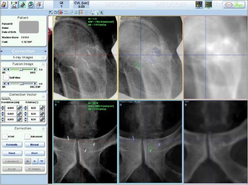
Figure 1: A screenshot of the VeriSuite interface showing a prostate case registration using fiducial marker alignment. Top three images are lateral view and the bottom three images are posterior-anterior view. Left are digital x-ray images, right are DRRs, and middle are fusion images.
To ensure the registration results are representative of our clinical practice, we requested the RTs to align the portal images to DRRs by following the same clinical protocol and procedure as used at our center. All RTs performed the study anonymously and were blind of the results from other RTs. After the RT performed the image registration, the resulting six degrees of freedom correction vector was recorded. In total, 81 sets of correction vectors were collected and analyzed.
The inter-observer variability was calculated by obtaining the standard deviation of the 10 users for each translational shift and rotational shift using below equation:
Where s is the standard deviation, n is the sample size (n =10 here), xi is the correction obtained by the ith RT, and is the mean result for all RTs.
RESULTS
A. Brain case and automatic registration
Figure 2 shows the six degrees of correction vectors for a brain case obtained by the 10 RTs. Also shown are the correction vectors averaged by the 10 RTs and automatically calculated by VeriSuite. The maximum translational shift difference among RTs was 3.8 mm in one direction (between User 1 and User 10 in y direction), and the inter-observer variations (1 SD) were 0.8 mm, 1.2 mm, and 0.4 mm in x, y, z respectively. Similarly, the maximum difference in rotational shift was 1.5ᵒ, and the inter-observer variations (1 SD) were 0.15ᵒ, 0.33ᵒ, and 0.42ᵒ in yaw, pitch, and roll. The automatic registration correction matched closely with the averaged data from the 10 RTs, within 0.3 mm in translational shift and 0.17ᵒ in rotational shift, indicating the automatic registration can be a reliable approach in brain case registration.
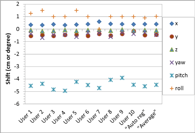
Figure 2: The six degrees of shift correction vectors for a brain case obtained by the 10 RTs (User 1, User 2, …, User 10), their averaged correction vector (Average), and the correction vector automatically calculated by VeriSuite (Auto reg).
B. Prostate
For the prostate case, we registered the patient using three different approaches, fiducial marker alignment, bony anatomy alignment, and the hybrid approach that used the bony anatomy for rotational correction and fiducial markers for translational correction, and the shifts of these three approaches are shown in figure 3. The inter-observer variation with fiducial markers was the least in both translational and rotational shifts. The s values for fiducial marker alignment were 0.5 mm, 0.7 mm, 0.5 mm, 0.7°, 0.2°, and 0° in x, y, z, yaw, pitch and roll, compared to 0.7 mm, 1.2 mm, 1.0 mm, 0.7°, 1.2°, and 0° for bony alignment and 0.7 mm, 1.0 mm, 1.4 mm, 0.6°, 1.1°, and 0° for the hybrid approach. The inter-observer variation seemed to be the least in lateral direction and largest in superior-inferior direction. Please note that s value was the largest in pitch and 0 for roll correction as no roll correction was applied based on our clinical practice for prostate setup.
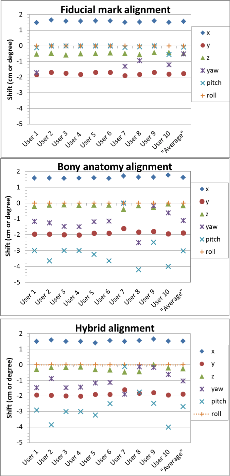
Figure 3: The six degrees of shift correction vectors for a prostate case obtained by the 10 RTs (User 1, User 2, …, User 10), and their averaged correction vector (Average) using three alignment approaches: 1) fiducial markers; 2) bony anatomy; and 3) hybrid - bony anatomy for rotational shifts then fiducial markers for translational shifts.
C. Other cases
The inter-observer variations on image registration for parotid, lung, pelvis and bladder cases based on the results of the 10 RT users are shown in figure 4. For comparison, the results for brain and prostate (fiducial marker alignment) are also included. The inter-observer variation (one standard deviation s) ranged from 1.2 to 2.0 mm for translational correction vector, and from 0.6 to 1.3 degrees for rotational angle correction for the six cases. s was the least for the prostate case using fiducial markers and largest for the bladder case. On average, s was the least in x direction and yaw, and the largest in z and pitch.
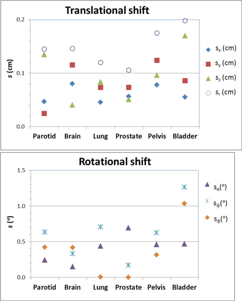
Figure 4: Inter-observer variation (s) of translational shifts in X (sx), Y (sy), Z (sz) and the vector magnitude (sr) and rotational shifts in yaw (sѳ), pitch (sѱ), and roll (sф) for various disease sites.
DISCUSSIONS
Our study indicates that the inter-observer variability in daily patient image alignment is not negligible. The inter-observer variability (s) was about 1-2 mm for translational shift, and 0.5-1.3° for rotational shift, depending on disease site. The result on translational shift for the prostate case using fiducial marker alignment is consistent with what was reported by Ullman et al. [15]. To appropriately estimate the lateral beam margin and smearing distance for adequate target coverage during proton treatment planning, we need to account for the inter-observer variability, together with other uncertainties such as target position and shape, intra-fraction errors, and phantom-transfer error due to factors such as proton beam and x-ray isocenter alignment inaccuracy and image resolution. For proton therapy where a tight planning margin is used, the inter observer variability could contribute considerably to the overall setup uncertainty and lead to potential target under coverage. Antolak et al. recommended that a margin of 1.65 SDs be used to have any point on the CTV surface to be within PTV 95% of time. Using this formula, for brain cases, the planning margin required due to inter-observer variability (1.5 mm SD) alone would be 1.65×1.5≈2.5 mm. Combined with other uncertainties (e.g., the proton beam and x-ray is center misalignment could be up to 1 mm according to our machine specification), the overall setup uncertainty could be about 3 mm or more. Therefore, a minimum planning margin of 3 mm should be used for brain cases. Inter-observer variability on rotational shift was rarely reported in literature, and our result indicates that both the rotational shift and its inter-observer variability could be large. The rotational variability in daily setup can affect the water equivalent thickness of proton beam path in addition to the target positioning during proton therapy. However, the clinical significance of rotational error depends on disease site and treatment technique. As reported by Sejpal et al. [22], the impact of rotational error of 3° and 5° for passive scattering proton therapy of prostate did not significantly change the dose to target coverage and critical organs; however, a rotational error of 2° or more would lead to substantial target under coverage for lung cancer treatment using intensity modulated proton therapy as reported by Suresh et al. [23]. Note that while more freedom of correction such as 5D or 6D registration would allow more accurate patient positioning, it could also add additional complexity in image registration, leading potential larger inter-observer variability.
Due to limited resources, we used only one case for each disease site, although we chose each case carefully to make sure it was representative of certain disease site. However, even for the same disease site, patient tumor and anatomy could vary case by case, and thus the behavior of image registration could vary accordingly case by case. In addition, to make the registration process close to daily clinical practice, we instructed the RTs to register the image anonymously, thus the correlation between the registration result and individual user experience was unknown.
While the VeriSuite system may provide sub-millimeter alignment for phantoms [11], the inter-observer variability could be large for clinical patient alignment. The magnitude of inter-observer variability depends on many factors, such as the complexity of disease site and patient anatomy, the method used for image alignment, the training and experience of the user, the quality of the image, and software limitations. Automatic registration could potentially be used to align patient more accurately and efficiently for brain cases, but its application on other sites such as the lung, where anatomic deformation or motion is large, seems to be challenging and needs to be explored further. Fiducial markers seem to be helpful in reducing inter-observer variation on patient alignment; however, implanting fiducial markers is an invasive procedure, and their use for cancer sites other than prostate and breast is not very common. The extent of user experience and training may have a large impact on the setup variability, as Fuss et al. reported that use of only experience users reduced the inter-observer variability largely for prostate setup using a stereotactic ultrasound-targeting device [24]. Therefore, it is important to provide the RTs with sufficient training and a clear instruction on how patient should be aligned. Given the sensitivity of proton beams to anatomy change, inter-observer variability on image alignment should be carefully evaluated and accounted for in patient setup uncertainty and treatment planning margin to ensure optimal tumor coverage and normal tissue sparing in proton therapy.
REFERENCES
- Engelsman M, Schwarz M, Dong L. Physics controversies in proton therapy. Semin Radiat Oncol. 2013; 23: 88-96. Ref.: https://goo.gl/4gbQgV
- Rosen L. Everything is changing in oncology and proton therapy. J Proton Ther. 2015; 1: 111. Ref.: https://goo.gl/zwd392
- Yin F, Wong J, Balter J, Benedict S, Craig J, et al. The role of in-room kV X-ray imaging for patient setup and target localization. Report of AAPM Task Group. 2009; 104. Ref.: https://goo.gl/rYpMVS
- De Los Santos J, Popple R, Agazaryan N, Bayouth JE, Bissonnette JP, et al. Image guided radiation therapy (IGRT) technologies for radiation therapy localization and delivery. Int J Radiat Oncol Biol Phys. 2013; 87: 33-45.Ref.: https://goo.gl/7QP8CU
- Fuss M, Salter BJ, Cavanaugh SX, Fuss C, Sadeghi A, et al. Daily ultrasound-based image-guided targeting for radiotherapy of upper abdominal malignancies. Int J Radiat Oncol Biol Phys. 2004; 59: 1245-1256. Ref.: https://goo.gl/iHRfcE
- Molloy JA, Chan G, Markovic A, McNeeley S, Pfeiffer D, et al. Quality assurance of U.S.-guided external beam radiotherapy for prostate cancer: report of AAPM Task Group 154. Med Phys. 2011; 38: 857-871. Ref.: https://goo.gl/1gjnSQ
- Wooten HO, Rodriguez V, Green O, Kashani R, Santanam L, et al. Benchmark IMRT evaluation of a Co-60 MRI-guided radiation therapy system. Radiother Oncol. 2015; 114: 402-405. Ref.: https://goo.gl/eFrX0L
- Oelfke U, Tucking T, Nill S, Seeber A, Hesse B, et al. Linac-integrated kV-cone beam CT: technical features and first applications. Med Dosim. 2006; 3: 62-70. Ref.: https://goo.gl/XHfpFn
- Morin O, Gillis A, Chen J, Aubin M, Bucci MK 3rd, et al. Megavoltage cone-beam CT: system description and clinical applications. Med Dosim. 2006; 31: 51-61. Ref.: https://goo.gl/WqIuHI
- Bert C, Metheany KG, Doppke KP, Taghian AG, Powell SN, et al. Clinical experience with a 3D surface patient setup system for alignment of partial-breast irradiation patients. Int J Radiat Oncol Biol Phys. 2006; 64: 1265-1274. Ref.: https://goo.gl/RAah6i
- Fattori G, Riboldi M, Pella A, Peroni M, Cerveri P, et al. Image guided particle therapy in CNAO room 2: implementation and clinical validation. Phys Med. 2015; 31: 9-15. Ref.: https://goo.gl/jxDrtO
- Depauw N, Batin E, Daartz J, Rosenfeld A, Adams J, et al. A novel approach to postmastectomy radiation therapy using scanned proton beams. Int J Radiat Oncol Biol Phys. 2015; 91: 427-434. Ref.: https://goo.gl/ffCgk0
- Enke C, Ayyangar KM, Saw CB, Zhen W, Thompson RB, et al. Inter-observer variation in prostate localization utilizing BAT. Int J Radiat Oncol Biol Phys. 2002; 54: 269. Ref.: https://goo.gl/ahKfKs
- Aubin M, Liu Y, Langen K, Shinohara K, Anezinos C, et al. Set-up verification using portal images of implanted prostate markers: an inter-observer study. Int J Radiat Oncol Biol Phys. 2002; 54: 269-270. Ref.: https://goo.gl/xSUqNI
- Ullman KL, Ning H, Susil RC, Ayele A, Jocelyn L, et al. Intra- and inter-radiation therapist reproducibility of daily isocenter verification using prostatic fiducial markers. Radiat Oncol. 2006; 1: 2. Ref.: https://goo.gl/FLxAde
- Court LE, Dong L, Taylor N, Ballo M, Kitamura K, et al. Evaluation of a contour-alignment technique for CT-guided prostate radiotherapy: an intra- and interobserver study. Int J Radiat Oncol Biol Phys. 2004; 59: 412-418. Ref.: https://goo.gl/VSUDZv
- Court LE, Allen A, Tishler R. Evaluation of the precision of portal-image-guided head-and-neck localization: an intra- and interobserver study. Med Phys. 2007; 34: 2704-2707. Ref.: https://goo.gl/tIx8VX
- Guckenberger M, Sweeney RA, Wilbert J, Krieger T, Richter A, et al. Image-guided radiotherapy for liver cancer using respiratory-correlated computed tomography and cone-beam computed tomography. Int J Radiat Oncol Biol Phys. 2008; 71: 297-304. Ref.: https://goo.gl/3buPTa
- Commission IE. IEC 61217 radiotherapy equipment-co-ordinates, movements and scales. International Electrotechnical Commission. 2011. Ref.: https://goo.gl/q0LxHM
- Pella A, Riboldi M, Tagaste B, Bianculli D, Desplanques M, et al. Commissioning and quality assurance of an integrated system for patient positioning and setup verification in particle therapy. Technol Cancer Res T. 2014; 13: 303-314. Ref.: https://goo.gl/Ece8Ao
- Walter S. Automatic patient alignment in six degrees of freedom for particle beam treatment. PTCOG; 2007 May 18-23; Wanjie, Shandong, China.
- Sejpal SV, Amos RA, Bluett JB, Levy LB, Kudchadker RJ, et al. Dosimetric changes resulting from patient rotational setup errors in proton therapy prostate plans. Int J Radiat Oncol Biol Phys. 2009; 75: 40-48. Ref.: https://goo.gl/w6Z32h
- Rana S, Zhang Y, Larson G, Vargas C, Dunn M, et al. Investigating dosimetric effect of rotational setup errors in IMPT planning of synchronous bilateral lung cancer. Int J Cancer Ther Oncol. 2015; 3. Ref.: https://goo.gl/99xLw5
- Fuss M, Cavanaugh SX, Fuss C, Cheek DA, Salter BJ. Daily stereotactic ultrasound prostate targeting: inter-user variability. Technol Cancer Res Treat. 2003; 2: 161-170. Ref.: https://goo.gl/QmxFHr