- Department of Neurosurgery, All India Institute of Medical Sciences, New Delhi, Delhi, India.
- Departments of Neuroradiology, All India Institute of Medical Sciences, New Delhi, Delhi, India.
Correspondence Address:
Amandeep Kumar, Department of Neurosurgery, All India Institute of Medical Sciences, New Delhi, Delhi, India.
DOI:10.25259/SNI_1010_2023
Copyright: © 2024 Surgical Neurology International This is an open-access article distributed under the terms of the Creative Commons Attribution-Non Commercial-Share Alike 4.0 License, which allows others to remix, transform, and build upon the work non-commercially, as long as the author is credited and the new creations are licensed under the identical terms.How to cite this article: V. L Ganesh1, Sundarakrishnan Dharanipathy1, V. Pavana1, Amandeep Kumar1, Leve Joseph Devarajan Sebastian2, Ajay Garg2. A computed tomography (CT)-based morphometric study of various skull base parameters and their anatomical relationships relevant to endoscopic endonasal skull base surgery. 01-Mar-2024;15:68
How to cite this URL: V. L Ganesh1, Sundarakrishnan Dharanipathy1, V. Pavana1, Amandeep Kumar1, Leve Joseph Devarajan Sebastian2, Ajay Garg2. A computed tomography (CT)-based morphometric study of various skull base parameters and their anatomical relationships relevant to endoscopic endonasal skull base surgery. 01-Mar-2024;15:68. Available from: https://surgicalneurologyint.com/surgicalint-articles/12776/
Date of Submission
22-Dec-2023
Date of Acceptance
02-Feb-2024
Date of Web Publication
01-Mar-2024
Abstract
Background: Endoscopic skull base surgery requires a thorough understanding of skull base anatomy. Orientation to regional anatomy to avoid complications like internal carotid artery injury can be assisted by knowledge of certain bony landmarks. These landmarks are themselves highly variable structures. This study focuses on the radiological morphometric characterization of these landmarks, which can be of great assistance to surgeons for better planning of endoscopic skull base approaches.
Methods: Computed tomography scans of patients without skull base pathologies were analyzed retrospectively for the following parameters – Vidian canal (VC) length, VC and foramen rotundum (FR) distance from midline, the angle between the axis of VC and petrous internal carotid artery (pICA) and between VC and palatovaginal canal, the horizontal, vertical and direct distances between VC and FR and the patterns of sphenoid sinus (SS) pneumatization.
Results: The VC-pICA angle was more obtuse and VC and FR were placed farther off the midline on the left as compared to the right side. Similarly, the distances between VC and FR were more on the left side. The VC length and distance of VC and FR from the midline were longer in males than in females. The VC-pICA angle was more obtuse in females. The post-sellar variant was the predominant pneumatization pattern seen (57.9%), and the incidence of lateral recess pneumatization was 15%.
Conclusion: The results of our study can be utilized for a better understanding of the anatomy of the skull base. In skull base pathologies with distorted anatomical landmarks, a basic understanding of their interrelations can be used to have a better anatomical orientation. All these measures can help in avoiding complications and make extended endoscopic approaches safe.
Keywords: Endoscopic skull base surgery, Extended endoscopic approaches, Foramen rotundum, Petrous internal carotid artery, Vidian canal
INTRODUCTION
Knowledge about anatomy paves the way for surgery. The radiological correlation of anatomy and its intraoperative application can be compared to driving a road with good-quality navigation. As the road carries certain signboards to avoid accidents, certain bony structures can be considered signboards for safely accessing the skull base. The complexity of skull base anatomy and intricate interrelations between important neurovascular structures make skull base endoscopic surgery a challenging field. As the internal carotid artery (ICA) is unavoidably encountered during extended endoscopic approaches (EEAs), its injury is the most feared complication. Identification of petrous internal carotid artery (pICA) and cavernous ICA is thus a crucial step in EEAs. One important anatomical landmark that can assist surgeons in identifying foramen lacerum (FL) and petrous ICA is the Vidian canal (VC), which can be localized during the early stages of exposure in EEAs.[
MATERIALS AND METHODS
This was a retrospective cross-sectional study conducted at a tertiary care center. Patients who had undergone CT scans for indications other than skull base pathologies, skull base fractures, and sinonasal pathologies and those who had not undergone previous skull base surgical intervention were identified. From this cohort, patients with 1 mm slice thickness CT scans were then included in the study. Only adult patients with an age of more than 18 years were included in the study. The images were retrieved from our picture archiving and communication system (PACS). All CT scans were performed using the Siemens Somatom Definition Edge multidetector CT (128 slice) scanner. The CT imaging protocol was as follows: gantry speed - 0.28 s/rotation, collimation 128 × 0.6 mm, table increment – 5 mm/, parameters - 100 kV, and effective mAs 430–490. Sections were reconstructed with 1 mm section thickness with zero interval in bone window settings for studying the skull base bony anatomy.
CT scans of patients meeting eligibility criteria were assessed independently by a neurosurgeon and a neuroradiologist. In cases with discordant findings, the images were re-evaluated to reach a consensus. For each included patient, the following measurements from both the right and left sides were measured using GEPACS software in axial, sagittal, and coronal planes [
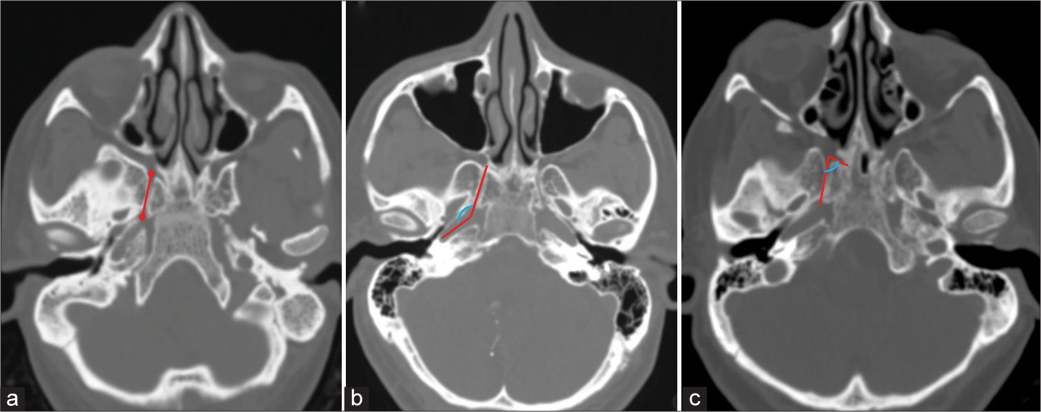
Figure 1:
Axial computed tomography images showing the method used to measure (a) Vidian canal (VC) length (represented by red line), (b) VC-petrous internal carotid artery angle (represented by blue curved line between two red lines), and (c) VC-palatovaginal canal angle (represented by blue curved line between two red lines).
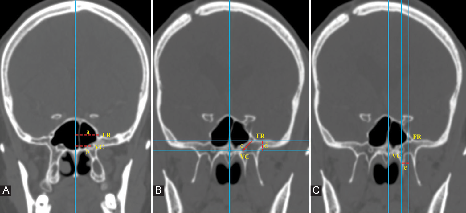
Figure 2:
In coronal computed tomography images, a vertical imaginary line is drawn in the midline along the vomer bone. (A) Distance of foramen rotundum (FR) and Vidian canal (VC) from the midline is measured (represented by ‘a’ and ‘b’ respectively). (B) Two horizontal lines are drawn, crossing the midpoint of VC and FR. The vertical distance between these two lines gives the vertical distance between FR and VC (represented by ‘d’). The direct distance between VC and FR (represented by ‘c’) is then measured. (C) The horizontal distance between VC and FR is measured as the distance between two vertical lines drawn across the centers of the two foramina (represented by ‘e’).
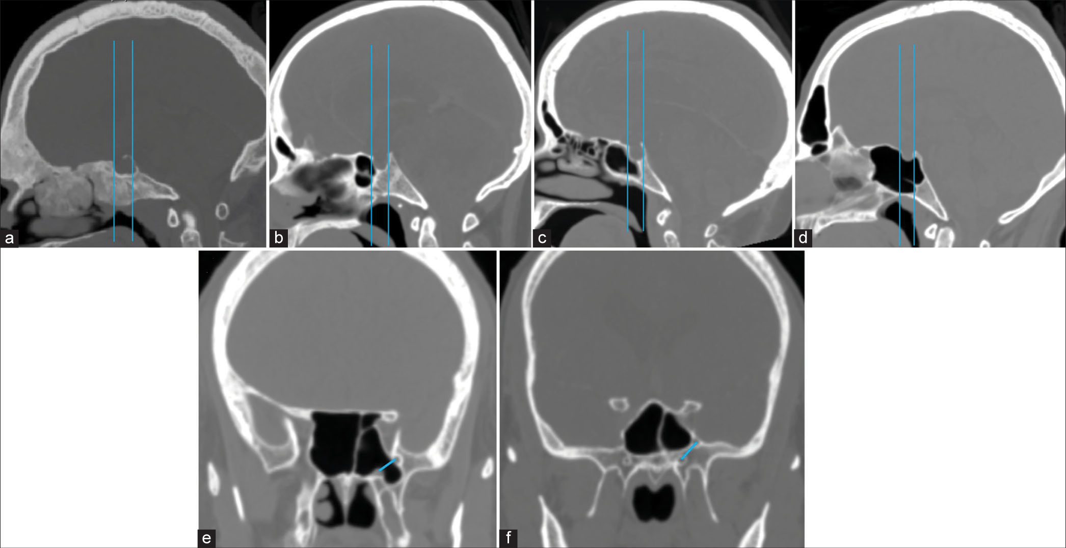
Figure 3:
(a-c) In sagittal computed tomography images, the two vertical lines drawn along the anterior and posterior walls of the pituitary fossa determine the type of SS pneumatization in a sagittal plane, which is classified as (a) Conchal, (b) Presellar, (c) Sellar, and (d) Postsellar types. (e and f) An oblique line connecting the centers of the Vidian canal and foramen rotundum determines the presence (d) or absence (e) of lateral recess pneumatization.
Length of VC
The length of VC was measured in the axial plane. To determine the length of VC, a line was drawn through the center of VC from its anterior to the posterior end [
VC-pICA angle
This was defined as the angle subtended between the axis of VC and that of the petrous carotid canal. It was measured in axial images. A line was drawn along the axis of VC. Another line was drawn along the axis of the petrous carotid canal at the level of VC. The angle subtended at the point where these two lines meet was measured and was termed the VC– petrous ICA angle [
VC-palatovaginal canal (PVC)
This was defined as the angle subtended between the axis of the VC and that of the PVC. It was measured in axial images. A line was drawn along the axis of VC. Another line was drawn along the axis of the PVC at the level of VC. The angle subtended at the point where these two lines meet was measured and was termed the VC-PVC angle [
Distance of VC and FR from the midline
An imaginary vertical line was drawn along the midline. Then, a line parallel to the midline and passing through the center of VC was drawn. The distance between these two lines gave the distance of VC from the midline. Similarly, the distance of FR from the midline was determined [
VC-FR distance
The distance between VC and FR was measured on coronal images. The shortest vertical distance between VC and FR was determined by drawing two horizontal lines passing through the centers of VC and FR. The distance between these two lines gave us the shortest vertical distance between VC and FR. The direct distance between VC and FR was also measured in this coronal image [
SS
SS pneumatization is highly variable. These variations are very diverse and frequent. We analyzed SS pneumatization for the following variations [
In the sagittal plane
In mid sagittal section, two tangents are drawn from the anterior and posterior walls of the pituitary fossa.
Conchal type–when the sinus is non-pneumatized Presellar type–when the pneumatization extends to the anterior line Sellar type–when the pneumatization extends to a point between two lines Postsellar type–when the pneumatization extends posteriorly to the second line.
In the coronal plane
Lateral recess pneumatization was classified into three types based on an imaginary oblique line connecting the medial edge of the anterior opening of VC and FR [
Nonpneumatized–Sphenoid body pneumatization without lateral extension Pneumatized lateral recess–Pneumatization extending beyond the oblique line described above Pneumatization extends into the lesser wing of the sphenoid/anterior clinoid process.
Statistical analysis
The data were analyzed using the STATA 16.0 (Stata Corp, College Station, TX) software. Categorical variables are presented as n (%), and continuous variables are presented as mean (standard deviation [SD]) or median (interquartile range) as applicable. Categorical variables were compared using the Fisher exact test or Chi-square test, wherever applicable, and continuous variables were compared using an independent sample Student’s t-test. Statistical significance was set at P < 0.05.
RESULTS
A total of 473 individuals who had undergone CT scans between January 2020 and December 2022 were included in the study. There were 263 males (55%) and 210 females (45%) in the study. The mean age was 40.91 ± 13.6 years in males and 42 ± 12.96 years in females (P = 0.377).
Baseline parameters
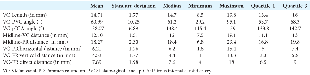
Baseline parameters were calculated after combining both sides (n = 946). The mean and median lengths of VC were 14.71 mm (SD–1.77) and 14.7 mm, respectively. The mean and median angles between VC and PVC were 60.99° (SD–10.25) and 61.2°, respectively. The mean and median angles between VC and petrous ICA were 138.07° (SD – 6.89) and 138.4°, respectively. The mean and median distances of VC from the midline were 12.10 mm (SD – 1.51) and 12 mm, respectively. The mean and median distances of FR from the midline were 18.27 mm (SD – 2.30) and 18.4 mm, respectively. The mean and median horizontal distances between FR and VC were 6.21 mm (SD – 1.76) and 6.2 mm, respectively. The mean and median vertical distances between VC and FR were 4.53 mm (SD – 1.77) and 4.4 mm, respectively. The mean and median direct distances between VC and FR were 7.89 mm (SD – 1.98) and 7.6 mm, respectively [
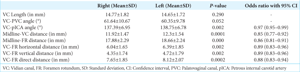
Skull base parameter–right versus left
The average lengths of VC on the right and left were 14.77 ± 1.82 and 14.65 ± 1.72, respectively (P = 0.290). The angle between the VC and PVC was 61.64 ± 10.67 mm on the right and 60.35 ± 9.78 mm on the left side (P = 0.052). The angle between pICA and VC was 137.39° ± 6.95° on the right and 138.75° ± 6.78° on the left side (P = 0.002). The distance of the VC from the midline measured on the right and left were 11.92 ± 1.47 and 12.3 ± 1.54, respectively (P = 0.0001). The distance of FR from the midline was 17.88 ± 2.29 on the right and 18.66 ± 2.24 on the left side (P = 0.000). The horizontal distances between VC and FR on the right and left were 6.04 ± 1.65 and 6.39 ± 1.85, respectively (P = 0.002) with odds of 0.89 (0.83–0.96; 95% confidence interval [CI]). The vertical distance between VC and FR on the right and left was 4.35 ± 1.74 and 4.72 ± 1.79 (P = 0.002), with an odds ratio of 0.89 (0.83–0.96; 95% confidence interval [CI]). The direct distance between VC and FR on the right and left was 7.65 ± 1.85 and 8.12 ± 2.07, respectively (P = 0.0002), with an odds ratio of 0.88 (0.83–0.94; 95% CI) [
Skull base parameters–males versus females
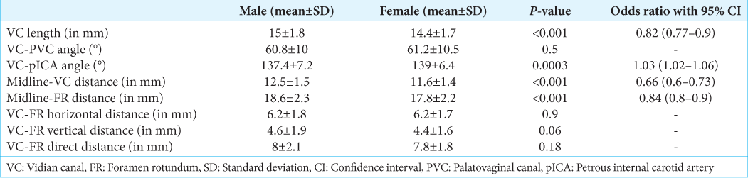
A subgroup analysis of morphometric parameters was done to analyze sex-specific variations. The mean length of VC was 15 ± 1.8 and 14.4 ± 1.7, respectively, in males and females (P = 0.001), and the odds ratio with 95% CI was 0.82 (0.77–0.9). The angle between VC and PVC in males and females was 60.8 ± 10 and 61.2 ± 10.5, respectively (P = 0.5). The angle between VC and Petrous ICA in males and females was 137.4 ± 7.2 and 139 ± 6.4, respectively (P = 0.0003). The distance of VC from the midline in males and females was 12.5 ± 1.5 and 11.6 ± 1.4, respectively (P < 0.001), and the odds ratio with 95% CI for the same was 0.66 (0.6–0.73). The distance of FR from the midline in males and females was 18.6 ± 2.3 and 17.8 ± 2.2 (P < 0.001), with an odds ratio of 0.84 (0.8–0.9). The horizontal distance between VC and FR in males and females was 6.2 ± 1.8 and 6.2 ± 1.7, respectively (P = 0.9). The vertical distance between VC and FR in males and females was 4.6 ± 1.9 and 4.4 ± 1.6, respectively (P = 0.06). The direct distance between VC and FR in males and females was 8 ± 2.1 and 7.8 ± 1.8, respectively (P = 0.18) [

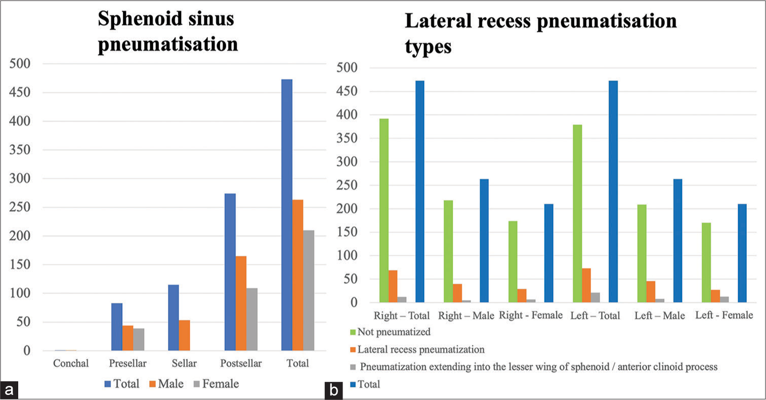
SS pneumatization
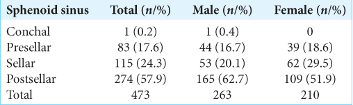
In our study, the post-sellar variant was the predominant pneumatization pattern seen in 57.9% (n = 274), followed by the seller variant in 24.3% (n = 115). The presellar and conchal were found in 17.6% (n = 83) and 0.2% (n = 1), respectively.
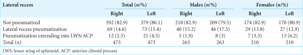
The lateral recess pneumatization was seen in 14.6% (n = 69) of the patients on the right side and 15.4% (n = 73) on the left side. The pneumatization beyond the lateral recess into the greater wing of the sphenoid or clinoid process was observed in 2.5% (n = 12) on the right and 4.5% (n = 21) on the left side [
DISCUSSION
The human skull base can be considered a pinnacle of craftsmanship with minute detailing to satisfy the purpose of various structures. There are various foramina through which neurovascular structures enter or exit the brain, and foramina can be widely used as a landmark for skull base surgery. The anterior opening of VC and FR are two important foramina that are crucial for anatomical orientation in the region. The VC is a reliable landmark to identify the pICA as well as the cavernous sinus and the Meckel’s cave.[
The SS has quite variable pneumatization patterns. SS pneumatization has an important bearing on the amount of drilling that is required in EEAs. The presence of a well-pneumatized SS makes it easier to access the Sella and identify important intrasphenoidal landmarks like medial/lateral optico-carotid recess, optic nerve, and cavernous ICA. In the presence of well-pneumatized SS, ON and ICA may be covered with very thin or no bone at all, thereby predisposing these structures to injury during surgery. On the other hand, when there is incomplete or no pneumatization, a lot of drilling is required, which not only increases the operative time but also increases the risk of injury to neurovascular structures (optic nerve, ICA).
VC and its relations
The VC is the conduit for the passage of the Vidian nerve and artery. The paired VCs are present along the line of fusion of pterygoid processes to the body of the sphenoid. The canal opens anteriorly into the medial part of the PPF and posteriorly at the upper part of the anterolateral edge of the FL.[
In our study, the mean length of VC was 14.71 ± 1.77mm, which is similar to what has been reported in the literature.[
The mean distance of VC from the midline was 12.1 ± 1.51mm. The mean distance of VC from the midline was shorter in females (11.6 ± 1.4 mm) as compared with males (12.5 ± 1.5mm). The more medial location of the anterior opening of the VC was probably responsible for the more obtuse VC-pICA angle seen in females.
All these anatomical parameters have relevance in EEAs. The position of the VC opening in relation to the midline is important to identify the location of the VC opening into PPF intraoperatively. The length of VC assumes importance in determining the extent of bony resection required to access the region of FL/pICA[
FR and its relations
FR is another important landmark in EEAs. The VC-FR distance is a landmark for quadrangular space during EEAs. The quadrangular space is limited medially and inferiorly by ICA, superiorly by the abducens nerve, and laterally by the maxillary division of the trigeminal nerve.[
In our study, the mean distance of FR from the midline was 18.27 mm (SD–2.30), which is similar to the literature reports.[
The mean horizontal, vertical, and direct distances between FR and VC were 6.21 mm (SD – 1.76), 4.53 mm (SD – 1.77), and 7.89 mm (SD – 1.98), respectively. The horizontal, vertical, and direct distances between VC and FR were more on the left side as compared with the right side and the difference was statistically significant. Variable findings have been reported in the literature. Kasemsiri et al.[
The FR was more laterally placed in males as compared to females (18.6 ± 2.3 and 17.8 ± 2.2), respectively (P < 0.001). The distances between VC and FR were slightly greater in males than females, though this difference was not statistically significant. A similar comparative study by Inal et al.[
Anatomy of the SS
As SS is a natural corridor of access during endonasal surgeries, many attempts have been made to delineate its anatomy with the help of CT scans.[
Sareen et al.[
The lateral sphenoid recess pneumatization is important in approaches to access the cavernous sinus, middle fossa, and petrous apex.[
CONCLUSION
The results of our study can be utilized for a better understanding of the anatomy of the skull base. In skull base pathologies with distorted anatomical landmarks, a basic understanding of their interrelations can be used to have a better anatomical orientation. All these measures can help in avoiding complications and make EEAs safe.
Ethical approval
The research/study was approved by the Institutional Review Board at All India Institute of Medical Sciences, New Delhi, number IEC-415/06.05.22, dated 09-05-2022.
Declaration of patient consent
Patients’ consent not required as patients’ identities were not disclosed or compromised.
Financial support and sponsorship
Nil.
Conflicts of interest
There are no conflicts of interest.
Use of artificial intelligence (AI)-assisted technology for manuscript preparation
The authors confirm that there was no use of artificial intelligence (AI)-assisted technology for assisting in the writing or editing of the manuscript and no images were manipulated using AI.
Disclaimer
The views and opinions expressed in this article are those of the authors and do not necessarily reflect the official policy or position of the Journal or its management. The information contained in this article should not be considered to be medical advice; patients should consult their own physicians for advice as to their specific medical needs.
References
1. Açar G, Çiçekcibaşı AE, Çukurova İ, Özen KE, Şeker M, Güler İ. The anatomic analysis of the vidian canal and the surrounding structures concerning vidian neurectomy using computed tomography scans. Braz J Otorhinolaryngol. 2017. 85: 136-43
2. Adin ME, Ozmen CA, Aygun N. Utility of the vidian canal in endoscopic skull base surgery: Detailed anatomy and relationship to the internal carotid artery. World Neurosurg. 2019. 121: e140-6
3. Bansberg SF, Harner SG, Forbes G. Relationship of the optic nerve to the paranasal sinuses as shown by computed tomography. Otolaryngol Head Neck Surg. 1987. 96: 331-5
4. Chin OY, Ghosh R, Fang CH, Baredes S, Liu JK, Eloy JA. Internal carotid artery injury in endoscopic endonasal surgery: A systematic review. Laryngoscope. 2016. 126: 582-90
5. Cho JH, Kim JK, Lee JG, Yoon JH. Sphenoid sinus pneumatization and its relation to bulging of surrounding neurovascular structures. Ann Otol Rhinol Laryngol. 2010. 119: 646-50
6. Citardi MJ, Gallivan RP, Batra PS, Maurer CR, Rohlfing T, Roh HW. Quantitative computer-aided computed tomography analysis of sphenoid sinus anatomical relationships. Am J Rhinol. 2004. 18: 173-8
7. Famurewa OC, Ibitoye BO, Ameye SA, Asaleye CM, Ayoola OO, Onigbinde OS. Sphenoid sinus pneumatization, septation, and the internal carotid artery: A computed tomography study. Niger Med J. 2018. 59: 7-13
8. Inal M, Muluk NB, Arikan OK, Şahin S. Is there a relationship between optic canal, foramen rotundum, and vidian canal?. J Craniofac Surg. 2015. 26: 1382-8
9. Kasemsiri P, Solares CA, Carrau RL, Prosser JD, Prevedello DM, Otto BA. Endoscopic endonasal transpterygoid approaches: Anatomical landmarks for planning the surgical corridor. Laryngoscope. 2013. 123: 811-5
10. Kassam AB, Vescan AD, Carrau RL, Prevedello DM, Gardner P, Mintz AH. Expanded endonasal approach: Vidian canal as a landmark to the petrous internal carotid artery. J Neurosurg. 2008. 108: 177-83
11. Mason EC, Hudgins PA, Pradilla G, Oyesiku NM, Solares CA. Radiographic analysis of the vidian canal and its utility in petrous internal carotid artery localization. Oper Neurosurg (Hagerstown). 2018. 15: 577-83
12. Mato D, Majime Y, Seiichiro H, Juan M, Naokatsu S. The vidian canal: Radiological features in Japanese population and clinical implications. Neurol Med Chir (Tokyo). 2015. 55: 71-6
13. Meng QG, Lu YT, Wang CX, Tan SP, Wei MH. Visualization of the vomerovaginal canal during endonasal transpterygoid approaches and CT imaging diagnosis. J Anat. 2019. 235: 246-55
14. Mohebbi A, Rajaeih S, Safdarian M, Omidian P. The sphenoid sinus, foramen rotundum and vidian canal: A radiological study of anatomical relationships. Braz J Otorhinolaryngol. 2017. 83: 381-7
15. Osawa S, Rhoton AL, Seker A, Shimizu S, Fujii K, Kassam AB. Microsurgical and endoscopic anatomy of the vidian canal. Neurosurgery. 2009. 64: 385-411 discussion 411-2
16. Oyama K, Tahara S, Hirohata T, Ishii Y, Prevedello DM, Carrau RL. Surgical anatomy for the endoscopic endonasal approach to the ventrolateral skull base. Neurol Med Chir (Tokyo). 2017. 57: 534-41
17. Papavasileiou G, Hajiioannou J, Kapsalaki E, Bizakis I, Fezoulidis I, Vassiou K. Vidian canal and sphenoid sinus: An MDCT and cadaveric study of useful landmarks in skull base surgery. Surg Radiol Anat. 2020. 42: 589-601
18. Pinheiro-Neto CD, Fernandez-Miranda JC, RiveraSerrano CM, Paluzzi A, Snyderman CH, Gardner PA. Endoscopic anatomy of the palatovaginal canal (palatosphenoidal canal): A landmark for dissection of the vidian nerve during endonasal transpterygoid approaches. Laryngoscope. 2012. 122: 6-12
19. Sareen D, Agarwal AK, Kaul JM, Sethi A. Study of sphenoid sinus anatomy in relation to endoscopic surgery. Int J Morphol. 2005. 23: 261-6
20. Vaezi A, Cardenas E, Pinheiro-Neto C, Paluzzi A, Branstetter BF, Gardner PA. Classification of sphenoid sinus pneumatizaion: Relevance for endoscopic skull base surgery. Laryngoscope. 2015. 125: 577-81
21. Vescan AD, Snyderman CH, Carrau RL, Mintz A, Gardner P, Branstetter B. Vidian canal: Analysis and relationship to the internal carotid artery. Laryngoscope. 2007. 117: 1338-42
22. Wang J, Bidari S, Inoue K, Yang H, Rhoton A. Extensions of the sphenoid sinus: A new classification. Neurosurgery. 2010. 66: 797-816
23. Yamashita S, Resende LA, Trindade AP, Zanini MA. A radiologic morphometric study of sellar, infrassellar and parasellar regions by magnetic resonance in adults. Springerplus. 2014. 3: 291