Abstract
Ayurveda oil contains numerous source of biological constituents which plays an important role in reducing the pain relief caused during bone fracture. The aim of the study is to fabricate the polyurethane (PU) scaffold for bone tissue engineering added with ayurveda amla oil using electrospinning technique. Scanning Electron Microscopy (SEM) analysis showed that the fabricated nanocomposites showed reduced fiber diameter (758 ± 185.46 nm) than the pristine PU (890 ± 116.91 nm). Fourier Infrared Analysis (FTIR) revealed the existence of amla oil in the PU matrix by hydrogen bond formation. The contact angle results revealed the decreased wettability (116° ± 1.528) of the prepared nanocomposites compared to the pure PU (100° ± 0.5774). The incorporation of amla oil into the PU matrix improved the surface roughness. Further, the coagulation assay indicated that the addition of amla oil into PU delayed the blood clotting times and exhibited less toxic to red blood cells. Hence, the fabricated nanocomposites showed enhanced physicochemical and better blood compatibility parameters which may serve as a potential candidate for bone tissue engineering.
Key words
polyurethane; ayurveda oil; electrospun scaffold; blood compatibility; bone tissue engineering
INTRODUCTION
The bone tissue engineering still faces challenges in the repair of bone defects caused by traumaMA ZW, HONG Y, NELSON DM, PICHAMUTHU JE, LEESON CE & WAGNER WR. 2011. Biodegradable polyurethane ureas with variable polyester or polycarbonate soft segments: Effects of crystallinity, molecular weight, and composition on mechanical properties. Biomacromol 12: 3265-3274., disease, or congenital malformations. The healing of small bone defects would occur spontaneously, but the healing of critical size defects wound not heal spontaneously and takes significant time to heal (GogolewskiGOGOLEWSKI S & GORNA K. 2007. Biodegradable polyurethane cancellous bone graft substitutes in the treatment of iliac crest defects. J Biomed Mater Res Part A 80: 94-101. & Gorna 2007). The ultimate aim of the bone tissue engineering is to improve the health of musculoskeletal by providing a living bone graft substitute to aid the repair of the damaged bone (TettehTETTEH G, KHAN AS, DELAINE-SMITH RM, REILLY GC & REHMAN IU. 2014. Electrospun polyurethane/hydroxyapatite bioactive Scaffolds for bone tissue engineering: The role of solvent and hydroxyapatite particles. J Mech Behavior Biomed Mater 39: 95-110. et al. 2014). Bone tissue engineering utilizes the use of materials to act as a carrier or template for implanted bone cells and also to induce the formation of bone from the surrounding tissue (BurgBURG KJL, PORTER S & KELLAM JF. 2000. Biomaterial developments for bone tissue engineering. Biomater 21: 2347-2359. et al. 2000). But the traditional treatment methods possess some disadvantages like scarcity of donor, supply limitation, an infectious and immune rejection which limited their usage in the bone repair (ZhaoZHAO L, ZHAO JL, WAN L & WANG SK. 2008. The study of the feasibility of segmental bone defect repair with tissue- engineered bone membrane: a qualitative observation. Strat. Trauma. Limb. Reconstr 3(2): 57-64. et al. 2008). Recently, the tissue engineered scaffold was reported to overcome these limitations of the traditional methods. In a bone tissue engineering, the develop scaffold should provide an 3D structure which should resemble the native structure of the extra cellular matrix (ECM). Further, it should possess biodegradable, biocompatible, highly porous, non-toxic and also supports the cell adhesion and growth (O’brienO’BRIEN FJ. 2011. Biomaterials & scaffolds for tissue engineering. Mater Today 14(3): 88-95. 2011, DhandayuthapaniDHANDAYUTHAPANI B, YOSHIDA Y, MAEKAWA T & KUMAR DS. 2011. Polymeric scaffolds in tissue engineering application: a review. Int J Polym Sci 2011: 1-19. et al. 2011).
The increasing interest in the tissue engineering applications is the fabrication of fibrous scaffold with similarity to the native structure of the ECM. One of the most capable techniques utilized for the fabrication of the fibrous structure is electrospinning technique. Electrospinning technique involves different process parameters which could be adjustable to develop a structure with the required topographical features. The bone tissue engineering mainly focuses on fabrication of the 3D scaffolds embedded with nanofibers that mimic the ECM (BrunBRUN P, GHEZZO F, ROSO M, DANESIN R, PALÙ G, BAGNO A, MODESTI M, CASTAGLIUOLO I & DETTIN M. 2011. Electrospun scaffolds of self-assembling peptides with poly (ethylene oxide) for bone tissue engineering. Acta Biomater 7(6): 2526-2532. et al. 2011). Electrospinning is a versatile technique which converts the polymers, as well as the composite material into nanofibers which closely resembles the ECM matrix. The success of nanofibers in tissue engineering applications was due to its large surface area to volume ratio and adequate porosity (HuangHUANG ZM, ZHANG YZ, KOTAKI M & RAMAKRISHNA S. 2003. A review on polymer nanofibers by electrospinning and their applications in nanocomposites. Compos Science Technol 63(15): 2223-2253. et al. 2003). Further, the nanofiber mats were reported to facilitate the cell growth, allow gaseous exchange and nutrients transport to support the tissue regrowth. In this study, Tecoflex, a medical grade polyurethane was utilized to fabricate the bone scaffold. PU is commonly used in biomedical applications because of its desirable properties like biodegradable nature, biocompatibility, good barrier properties, oxygen permeability and mechanical properties (LambaLAMBA NMK, WOODHOUSE KA & COOPER SL. 1998. Polyurethanes in Biomedical Applications. CRC Press. et al. 1998, Ma et al. 2011).
Further, the polyurethane was blended with amla oil to improve its biological properties. Amla oil is an ayurvedic solution which contains a rich source of antioxidants. It also contains several nutrients such as iron, vitamin A, C, fiber, potassium, magnesium, and calcium (https://www.thefusionmodel.com/amla-oil-benefits-uses-side-effects/). Bone mineralization is the process in which the minerals are deposited in the organic ECM which facilitates the bone healing (AparicioAPARICIO C & GINEBRA MP. 2015. Biomineralization and biomaterials: fundamentals and applications. Woodhead Publishing. & Ginebra 2015). Since, the amla oil constitutes various minerals (potassium, magnesium, and calcium) which might be putatively enhanced the bone mineralization for efficient bone remodeling. Further, the antioxidant behavior was reported to control the oxidative stress (FitzmauriceFITZMAURICE SD, SIVAMANI RK & ISSEROFF RR. 2011. Antioxidant therapies for wound healing: a clinical guide to currently commercially available products. Skin Pharmacol Physiol 24(3): 113-126. et al. 2011) which may also facilitate the bone healing process. The goal of this research is to fabricate PU and PU/amla oil membrane using electrospinning technique and investigate their physico-chemical characteristics and blood compatibility assessments.
MATERIALS AND METHODS
The homogeneous solution of Polyurethane (Tecoflex EG-80A, Lubrizol) and amla oil (obtained locally) were prepared by dissolving in Dimethylformamide (DMF) (Sigma Aldrich, UK) to prepare the homogeneous solution. In this present study, PU (9 wt%) solution was prepared and blended with 4 wt% concentration of amla oil to fabricate the electrospun nanocomposite membrane. The amla oil homogeneous solution was mixed to PU homogeneous solution at a ratio of 8:1 (v/v). The PU and PU amla oil membranes were fabricated through conventional electrospinning setup. The prepared homogeneous solutions were taken in the 10 ml syringe and attached to the syringe pump. For both samples, the nanofibers were attained at a voltage power supply of 10 kV was with a flow rate of 0.5 ml/hr. The nanofibers were collected on the collector drum which was placed 20 cm from the needle. Finally, the fabricated nanofibrous scaffolds were vacuum dried for 24 h to remove the residual DMF.
Physico-Chemical Characterization
Scanning electron microscopy (SEM)
The electrospun membranes were characterized by means of SEM to analyze the fibrous morphology and their fiber diameters. Samples from the electrospun membranes were coated with gold, mounted on an aluminum stub and the scanning was performed to attain the SEM images. From the captured images, the average fiber diameter and fiber distribution were calculated using Image J by measuring at least individual 50 fibers randomly.
Chemical and structural analysis
Fourier transform infrared (FTIR) spectroscopy for the electrospun membranes were carried out in attenuated total reflection mode (Thermo Fisher Co, Waltham, MA) to analyze their absorption bands. The spectra of the electrospun membranes were inspected at a wavelength of 600 and 4000 cm-1 with a resolution of 4 cm-1.
Contact angle measurements
Video contact angle (VCA) Optima contact angle measurement unit was used to calculate the static contact angles for electrospun membranes. Deionized water with a size of 0.5 µL was automatically dropped onto the electrospun membranes and the static image was captured using video cam. The contact angle was calculated using computer integrated software and experiment was repeated for three different trials to determine the mean value.
Atomic force microscopy (AFM)
AFM was performed using an AFM equipment in the normal atmosphere to determine the surface roughness of the electrospun membranes. Qualitative fiber roughness of the electrospun membranes was determined from a 20 × 20 μm image with 256 * 256 pixels.
Thermogravimetric analysis (TGA)
TGA was performed using TGA equipment in the nitrogen atmosphere to determine their thermal stability. The thermal stability was measured by heating a sample in the temperature range of 30°C to 1000°C at a rate of 10°C min-1.
Mechanical testing
Tensile tests for the fabricated scaffolds were performed using uniaxial tensile machine. The test samples were prepared according to ASTM standard D882-10. Initially, the samples with a size of 40 * 10 mm was cut and mounted onto the clamp ends of the tensile machine. After clamping, the sample was pulled at a rate of 5 mm/min until fracture with load cell of 500 N. The computer integrated software generates the stress-strain curve thorough which the values of tensile strength and the young’s modulus were determined.
Coagulation Assays
Activated partial thromboplastin time
The intrinsic pathway of the electrospun membranes was determined through calculating APTT. To begin the assay, the electrospun membranes (0.5 × 0.5 cm2) were incubated with 50 μL of platelet-poor plasma at 37°C. After incubation, it was further added with 50 μL rabbit brain cephalin followed by adding of 50 µL of CaCl2. Using a needle, the mixture was stirred to initiate the clot formation and the APTT was measured (BalajiBALAJI A, JAGANATHAN SK, ISMAIL AF & RAJASEKAR R. 2016. Fabrication and hemocompatibility assessment of novel polyurethane-based bio-nanofibrous dressing loaded with honey and carica papaya extract for the management of burn injuries. Int J Nanomed 11: 4339-4355 et al. 2016).
Prothrombin time
The extrinsic pathway of electrospun membranes was determined through calculating PT. For PT assay, the samples were incubated with platelet-poor plasma (50 μL) at 37°C followed by adding 50 μL of NaCl-thromboplastin (Factor III). Using a needle, the mixture was stirred to initiate the clot formation and the PT was measured (Balaji et al. 2016).
Hemolysis assay
To perform the assay, the electrospun membranes (1 cm × 1 cm) were equilibrated in saline solution for 30 min at 37°C. Then, the samples were incubated with citrated blood diluted in silane at a ratio of 4:5 for 60 min at 37°C. After, the incubated membranes were taken out and centrifuged at 1000 rpm for 5 min. Finally, the fresh supernatant was collected and the absorbance was measured at 545 nm to measure the release of hemoglobin. The percentage of hemolysis was calculated as discussed earlier (Balaji et al. 2016).
Statistical analysis
All test were done three times independently and analyzed using Unpaired t-test to determine the statistical significance. The attained values are expressed as mean ± SD. In case of qualitative experiments, a representative of three images is shown.
RESULTS AND DISCUSSION
Figure 1 display the SEM morphology of neat PU and PU blended with amla oil scaffolds. The morphological analysis indicated that the nanofibers of the fabricated PU and PU blended scaffolds were randomly oriented and beadles morphology. The fiber diameters of PU and PU/amla oil membranes were 890 ± 116.91 nm and 758 ± 185.46 nm whereas their fiber distribution curve as shown in Figure S2 - Supplementary Material SUPPLEMENTARY MATERIAL Figures. S2, S7, S8, S9 and S10 . Fiber diameters of the electrospun nanocomposites were observed to be decreased with the incorporation of the amla oil into the PU matrix. PrabhakaranPRABHAKARAN MP, VENUGOPAL J & RAMAKRISHNA S. 2009. Electrospun nanostructured scaffolds for bone tissue engineering. Acta Biomater 5(8): 2884-2893. et al. 2009 fabricated scaffolds comprising poly-L-lactide added with hydroxyapatite for bone tissue engineering. It was observed and proved that the addition of hydroxyapatite into PLLA matrix resulted in the reduction in fiber diameter and exhibited an enhanced proliferation of the osteoblast cells. Our prepared developed nanocomposites showed smaller fiber diameter than the pure PU which might favor the enhanced osteoblast cell proliferation for new bone tissue growth.

SEM images of (a) PU membrane (lower magnification) (b) PU/Amla oil nanocomposites (lower magnification) (c) PU membrane (higher magnification) (d) PU/Amla oil nanocomposites (higher magnification).
Figure 3 depicts the ATR-FTIR analysis of electrospun PU and PU/amla oil nanocomposites which denotes the characteristics peaks present in the membranes. The spectra of PU membrane includes 3323 cm-1 indicates the NH stretching, 2939 cm-1 and 2854 cm-1 attributed to CH stretching, 1730cm-1 and 1703 cm-1 denotes the carbonyl stretching, 1597cm-1 and 1531cm-1 corresponds to the vibrations of NH stretching, 1413 cm-1 implies the vibrations of CH stretching and 1221cm-1 and 1104 cm-1 denotes the CO stretch corresponding to alcohol group (Balaji et al. 2016). In our work, incorporation of amla oil into the polyurethane matrix resulted in the decrease of the intensity of peaks for the PU/amla oil composite. This clearly indicates the formation of strong hydrogen bond between the CH and CO found in the amla oil and polyurethane (UnnithanUNNITHAN AR, TIRUPATHI PB, GNANASEKARAN G, SEENIVASAN K, BARAKAT NASSER AM, JUNG Y-S, SHANMUGAM A & KIM HY. 2012. Emu oil-based electrospun nanofibrous scaffolds for wound skin tissue engineering. Colloids. Surf. A: Physicochem. Eng Asp 415: 454-460. et al. 2012). Moreover, a clean confirmation of their interaction was observed through the shift in the peak position. The CH stretch in pure PU from 2939 cm-1 to 2925 cm-1 in PU/amla oil nanocomposites which indicates that the PU matrix have amla oil constituents (TijingTIJING LD, RUELO MTG, AMARJARGAL A, PANT HR, PARK C-H, KIM DW & KIM CS. 2012. Antibacterial and superhydrophilic electrospun polyurethane nanocomposite fibers containing tourmaline nanoparticles. Chem Eng J 197: 41-48. et al. 2012).

The water wettability results for electrospun PU and PU/amla oil nanocomposites were measured through VCA optima contact angle measurements. The results indicated that PU membrane exhibited water contact angle of 100° ± 0.5774 whereas electrospun PU/amla oil nanocomposite showed an angle of 116° ± 1.528 respectively. Hence, the incorporation of amla oil decreases the wetting behavior of PU. JansenJANSEN EJ, SLADEK RE, BAHAR H, YAFFE A, GIJBELS MJ, KUIJER R, BULSTRA SK, GULDEMOND NA, BINDERMAN I & KOOLE LH. 2005. Hydrophobicity as a design criterion for polymer scaffolds in bone tissue engineering. Biomater 26(21): 4423-4431. et al. 2005 suggested that the hydrophobic surface might absorb more proteins which results in the enhanced healing of bone defects. Hence, the newly developed electrospun nanocomposites showed hydrophobic behavior which might favor enhanced absorption of proteins for the healing of bone defects.
The thermal analysis of electrospun PU, PU/amla oil nanocomposites were displayed in Figure 4a and 4b. It was observed that PU membrane shows initial degradation temperature at 276°C and it was slightly shifted to 274° in electrospun PU/amla oil nanocomposites. Hence, the thermal stability of the PU membrane does not change significantly with the incorporation of amla oil. At 1000°C, the PU was showed less weight residue percentage than the electrospun nanocomposite. The weight residue percentage for PU was found to be only 0.47%, while the electrospun PU/amla oil nanocomposites, it was increased to 0.91% indicating an interaction between PU with amla oil. Further, the DTG curve of PU and PU/amla oil nanocomposites were displayed in Figure 5a and 5b. Electrospun PU membrane depicted three weight loss curve in first weight loss begins at 223°C to 348°C, the second loss occurs at 348°C to 446°C and the final loss seen at 557°C to 684°C. In the case of PU/amla oil nanocomposites, it showed two weight loss curve in which the initial weight begins at 211°C to 356°C and the second loss begins at 356°C to 508°C respectively. In PU/amla oil nanocomposites, the number of weight loss peaks were decreased compared to the pristine PU indicating an interaction between amla oil and polyurethane matrix. This interaction confirms the incorporation of amla oil in the polymer matrix thereby reducing the weight loss peaks observed in the polyurethane.


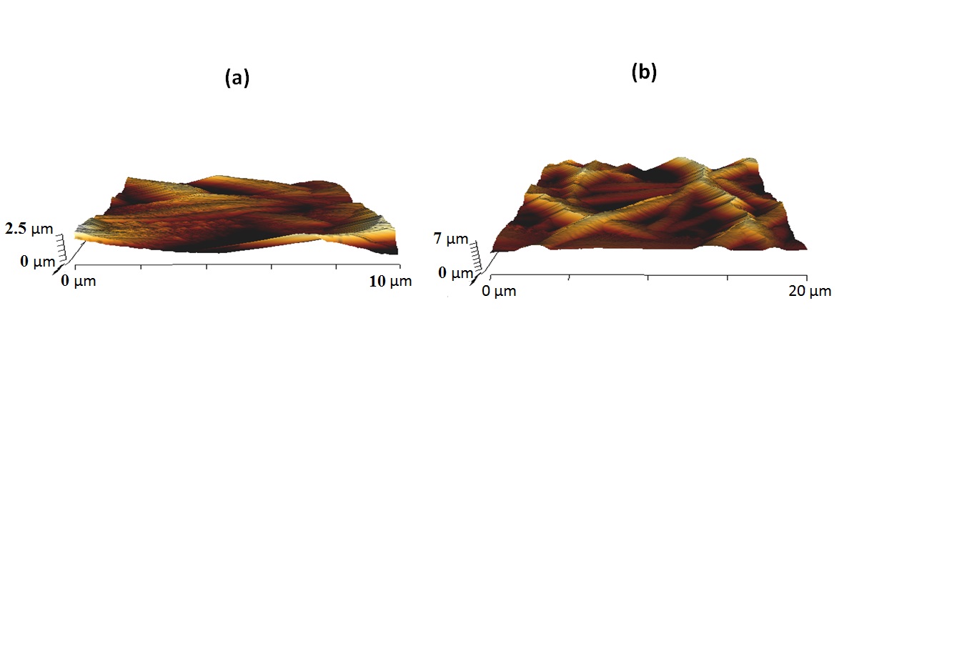
The AFM images of the electrospun PU and PU/amla oil nanocomposites were indicated in Figure 6a and 6b. AFM measurements of the electrospun PU/amla oil nanocomposites revealed that mean surface roughness was increased than the pure PU membrane. The measured roughness of the PU membrane was observed to be 313 nm, while the electrospun PU/amla oil nanocomposites showed average surface roughness of 603 nm respectively. The AFM measurements revealed that the fabricated nanocomposites showed rougher surfaces than the pristine PU because of active amla oil constituents present in the amla oil. NikpourNIKPOUR MR, RABIEE SM & JAHANSHAHI M. 2012. Synthesis and characterization of hydroxyapatite/ chitosan nanocomposite materials for medical engineering applications. Compos Part B 43: 1881-1886. et al. 2012 prepared a nanocomposite for medical engineering comprising hydroxyapatite and chitosan materials and observed that the addition of hydroxyapatite into chitosan membrane favored the increase in the surface roughness and our fabricated composites which correlates with their observations.

The tensile strength of the electrospun PU and PU/amla oil nanofibrous membranes were shown in Figure S7. It is found that the tensile strength for pristine PU was increased with the addition of amla oil nanofibers. The pristine PU showed a tensile strength of 7.12 MPa, while the electrospun PU/amla oil composites showed a tensile strength of 16.1 MPa respectively. Several studies have reported that the smaller diameters have favored the enhanced tensile strength (JeonJEON HJ, KIM JS, KIM TG, KIM JH, YU WR & YOUK JH. 2008. Preparation of poly (ɛ-caprolactone)-based polyurethane nanofibers containing silver nanoparticles. Appl Surf Sci 254(18): 5886-5890. et al. 2008, WongWONG SC, BAJI A & LENG S. 2008. Effect of fiber diameter on tensile properties of electrospun poly (ɛ-caprolactone). Polym 49(21): 4713-4722. et al. 2008, QianQIAN Y, ZHANG Z, ZHENG L, SONG R & ZHAO Y. 2014. Fabrication and characterization of electrospun polycaprolactone blended with chitosan-gelatin complex nanofibrous mats. J Nanomater 2014: 1. et al. 2014). In our study, the electrospun PU/amla oil composite showed smaller fiber diameter which might be ascribed for its enhanced tensile strength.
The blood clotting time of electrospun PU and PU/amla oil nanocomposites were measured through APTT and PT assay as indicated in Figures S8 and S9. The coagulation assay showed the blood clotting time of the electrospun nanocomposites was observed to be prolonged than the control. The prolonged blood clotting time was due to the presence of amla oil in the PU matrix. In APTT assay, the PU membrane showed blood clotting time of 175.3 ± 4.041 s, while blood clotting time of electrospun PU/amla oil nanocomposites was observed to be 187.7 ± 6.110 respectively. Similarly, in APTT assay, the PU membrane showed blood clotting time of 76.33 ± 2.517 s, while blood clotting time of electrospun PU/amla oil nanocomposites was observed to be 83.33 ± 1.528 s respectively. Further, hemolysis assay was carried out for the fabricated membranes to analyze their safety to RBCs. It was observed that the hemolytic percentage of PU membrane was observed to 2.48%, while for the electrospun PU/amla oil nanocomposites, it was found to 1.63% respectively as denoted in Figure S10. The results clearly indicate that the electrospun PU/amla oil nanocomposites exhibited improved safety to RBC. The developed nanocomposites were classified as a non-hemolytic material because the displayed hemolytic index was observed to be below 2% (Balaji et al. 2016). MilleretMILLERET V, HEFTI T, HALL H, VOGEL V & EBERLI D. 2012. Influence of fiber diameter and surface roughness of electrospun vascular grafts on blood activation. Acta Biomater 8(12): 4349-4356 et al. 2012 electrospun scaffolds utilizing Degarapol and PLGA and studied the influence of fiber diameter on blood clotting on electrospun scaffolds comprising Degarapol and PLGA. It was reported that the scaffolds with smaller fiber diameter showed delayed blood clotting and in our study, the developed nanocomposites showed enhanced blood compatibility which might have influenced the enhanced blood compatibility.
CONCLUSION
In this research, the PU scaffold incorporated with amla oil was fabricated using electrospinning technique. The SEM analysis revealed that the fabricated PU and blended nanocomposites showed smooth fibers without any beads defects. The fabricated nanocomposites showed reduced fiber diameter than the pristine PU. The FTIR and TGA analysis revealed the existence of amla oil in the PU matrix. The contact angle results revealed the decreased wettability of the prepared nanocomposites compared to the pure PU. The addition of amla oil into the PU matrix improved the surface roughness and the anticoagulant behavior. The developed nanocomposites exhibited excellent physicochemical and blood compatibility properties. However, further studies involving the in vitro biodegradation of the fabricated composite, the cytotoxic behavior and in vivo bone formation are essential to assess the application of the PU-based nanocomposites in bone tissue engineering
REFERENCES
- APARICIO C & GINEBRA MP. 2015. Biomineralization and biomaterials: fundamentals and applications. Woodhead Publishing.
- BALAJI A, JAGANATHAN SK, ISMAIL AF & RAJASEKAR R. 2016. Fabrication and hemocompatibility assessment of novel polyurethane-based bio-nanofibrous dressing loaded with honey and carica papaya extract for the management of burn injuries. Int J Nanomed 11: 4339-4355
- BRUN P, GHEZZO F, ROSO M, DANESIN R, PALÙ G, BAGNO A, MODESTI M, CASTAGLIUOLO I & DETTIN M. 2011. Electrospun scaffolds of self-assembling peptides with poly (ethylene oxide) for bone tissue engineering. Acta Biomater 7(6): 2526-2532.
- BURG KJL, PORTER S & KELLAM JF. 2000. Biomaterial developments for bone tissue engineering. Biomater 21: 2347-2359.
- DHANDAYUTHAPANI B, YOSHIDA Y, MAEKAWA T & KUMAR DS. 2011. Polymeric scaffolds in tissue engineering application: a review. Int J Polym Sci 2011: 1-19.
- FITZMAURICE SD, SIVAMANI RK & ISSEROFF RR. 2011. Antioxidant therapies for wound healing: a clinical guide to currently commercially available products. Skin Pharmacol Physiol 24(3): 113-126.
- GOGOLEWSKI S & GORNA K. 2007. Biodegradable polyurethane cancellous bone graft substitutes in the treatment of iliac crest defects. J Biomed Mater Res Part A 80: 94-101.
- HUANG ZM, ZHANG YZ, KOTAKI M & RAMAKRISHNA S. 2003. A review on polymer nanofibers by electrospinning and their applications in nanocomposites. Compos Science Technol 63(15): 2223-2253.
- JANSEN EJ, SLADEK RE, BAHAR H, YAFFE A, GIJBELS MJ, KUIJER R, BULSTRA SK, GULDEMOND NA, BINDERMAN I & KOOLE LH. 2005. Hydrophobicity as a design criterion for polymer scaffolds in bone tissue engineering. Biomater 26(21): 4423-4431.
- JEON HJ, KIM JS, KIM TG, KIM JH, YU WR & YOUK JH. 2008. Preparation of poly (ɛ-caprolactone)-based polyurethane nanofibers containing silver nanoparticles. Appl Surf Sci 254(18): 5886-5890.
- LAMBA NMK, WOODHOUSE KA & COOPER SL. 1998. Polyurethanes in Biomedical Applications. CRC Press.
- MA ZW, HONG Y, NELSON DM, PICHAMUTHU JE, LEESON CE & WAGNER WR. 2011. Biodegradable polyurethane ureas with variable polyester or polycarbonate soft segments: Effects of crystallinity, molecular weight, and composition on mechanical properties. Biomacromol 12: 3265-3274.
- MILLERET V, HEFTI T, HALL H, VOGEL V & EBERLI D. 2012. Influence of fiber diameter and surface roughness of electrospun vascular grafts on blood activation. Acta Biomater 8(12): 4349-4356
- NIKPOUR MR, RABIEE SM & JAHANSHAHI M. 2012. Synthesis and characterization of hydroxyapatite/ chitosan nanocomposite materials for medical engineering applications. Compos Part B 43: 1881-1886.
- O’BRIEN FJ. 2011. Biomaterials & scaffolds for tissue engineering. Mater Today 14(3): 88-95.
- PRABHAKARAN MP, VENUGOPAL J & RAMAKRISHNA S. 2009. Electrospun nanostructured scaffolds for bone tissue engineering. Acta Biomater 5(8): 2884-2893.
- QIAN Y, ZHANG Z, ZHENG L, SONG R & ZHAO Y. 2014. Fabrication and characterization of electrospun polycaprolactone blended with chitosan-gelatin complex nanofibrous mats. J Nanomater 2014: 1.
- TETTEH G, KHAN AS, DELAINE-SMITH RM, REILLY GC & REHMAN IU. 2014. Electrospun polyurethane/hydroxyapatite bioactive Scaffolds for bone tissue engineering: The role of solvent and hydroxyapatite particles. J Mech Behavior Biomed Mater 39: 95-110.
- TIJING LD, RUELO MTG, AMARJARGAL A, PANT HR, PARK C-H, KIM DW & KIM CS. 2012. Antibacterial and superhydrophilic electrospun polyurethane nanocomposite fibers containing tourmaline nanoparticles. Chem Eng J 197: 41-48.
- UNNITHAN AR, TIRUPATHI PB, GNANASEKARAN G, SEENIVASAN K, BARAKAT NASSER AM, JUNG Y-S, SHANMUGAM A & KIM HY. 2012. Emu oil-based electrospun nanofibrous scaffolds for wound skin tissue engineering. Colloids. Surf. A: Physicochem. Eng Asp 415: 454-460.
- WONG SC, BAJI A & LENG S. 2008. Effect of fiber diameter on tensile properties of electrospun poly (ɛ-caprolactone). Polym 49(21): 4713-4722.
- ZHAO L, ZHAO JL, WAN L & WANG SK. 2008. The study of the feasibility of segmental bone defect repair with tissue- engineered bone membrane: a qualitative observation. Strat. Trauma. Limb. Reconstr 3(2): 57-64.
Publication Dates
-
Publication in this collection
30 Mar 2020 -
Date of issue
2020
History
-
Received
19 Apr 2018 -
Accepted
22 Nov 2018