Abstract
Li[Ni0.42Mn0.42Co0.16]O2 (NMC442)/graphite pouch cells with 1 M LiPF6 in ethylene carbonate (EC): ethyl methyl carbonate (EMC) (3:7 by weight) electrolyte containing 2 wt% vinylene carbonate (VC), 2 wt% prop-1-ene-1,3 sultone (PES), or 2 wt% PES + 1 wt% tris(trimethylsilyl) phosphite (TTSPi) + 1 wt% methylene methanedisulfonate (MMDS) ("PES-211") were subjected to cycling tests at various upper cut-off voltages from 4.2 to 4.7 V. After every 10 cycles, the pouch cells were charged or discharged to 3.8 V and evaluated using electrochemical impedance spectroscopy (EIS). This approach allows the impact of electrolyte additives on the impedance of cells cycled to different cut-off voltages to be studied systematically. The addition of 2% PES or "PES-211" proved to be beneficial in suppressing impedance growth when cells are cycled up to and above 4.4 V. Long-term cycling tests between 3.0 V and 4.4 V at 45°C showed that "PES-211" had the best capacity retention (∼85%) and the least impedance growth after 500 cycles. The results suggest the use of "PES-211" could lead to longer lived and higher power NMC/graphite Li-ion cells with better tolerance to high voltage (4.4 V) which will improve energy density.
Export citation and abstract BibTeX RIS

This is an open access article distributed under the terms of the Creative Commons Attribution 4.0 License (CC BY, http://creativecommons.org/licenses/by/4.0/), which permits unrestricted reuse of the work in any medium, provided the original work is properly cited.
Lithium-ion cells are now widely used in various applications ranging from portable electronics to electrified vehicles.1 However, they still suffer from limited life-time due to the parasitic reactions between charged electrode materials and electrolytes during cycling or storage.2 The addition of electrolyte additives is one of the most economical and effective ways to improve the performance (e.g. calendar life, impedance, safety etc.) of lithium-ion cells.3,4
The most famous additive, vinylene carbonate (VC) has been shown to be able to reduce charge end-point capacity slippage and increase coulombic efficiency (CE) for Li[Ni1/3Mn1/3Co1/3]O2 (NMC111)/Li5 or Li[Ni0.42Mn0.42Co0.16]O2 (NMC442)/graphite cells6 at a charge cut-off voltage of ∼ 4.2 V. Xia et al.7 showed that prop-1-ene-1,3 sultone (PES), a novel sulfur-containing electrolyte additive, could also increase CE, decrease charge end-point capacity slippage and even suppress gas production of NMC111/graphite pouch cells with a charge cut-off voltage of 4.2 V, which made PES more attractive than VC. Systematic studies by Nelson et al.8 showed that 2% PES is the optimum concentration of PES for NMC111/graphite and NMC442/graphite cells. Recently, a major study of the effects of 19 electrolyte additives and their combinations on NMC111/graphite cells by Wang et al.9 showed that selected ternary or quaternary additive combinations, especially 2% PES + 1% methylene methanedisulfonate (MMDS) + 1% tris(trimethylsilyl) phosphite (TTSPi) ("PES-211") gave significant improvements in long-term cycling, CE, and charge end-point capacity slippage.
NMC442/graphite pouch cells can, in principle, be operated up to 4.7 V, which will access more positive electrode capacity and increase energy density. However, high voltage operation has proven to be difficult because many electrolyte solvents and additives are unstable at higher voltage, which can cause a dramatic decrease in the lifetimes of Li-ion cells.10,11 Furthermore, Li-ion cells must maintain an acceptable power capability during cycling, which suggests that low impedance must be maintained during charge-discharge cycling.12,13 Therefore, it is of utmost importance to systematically study the effects of some promising additives on the impedance changes of Li-ion cells cycled to different charge cut-off voltages. In this work, a few selected electrolyte additives or additive combinations were studied in NMC442/graphite cells with upper cut-off voltages ranging from 4.2 to 4.7 V in steps of 0.1 V. After every 10 cycles, the impedance of the cells was measured using electrochemical impedance spectroscopy (EIS). Finally, cells with the same additives or additive blend were subjected to long-term cycling between 3.0 and 4.4 V at 45°C with currents corresponding to C/2.5. Gas evolution was monitored using the methods described by Aiken et al.14 to verify that these additive sets did not cause gassing problems.
The experimental results show that "PES-211" cannot only suppress impedance growth during cycling up to 4.5 V, but also leads to excellent capacity retention (∼85% after 500 cycles) in NMC442/graphite cells when cycled between 3.0 V and 4.4 V at 45°C. These features indicate that "PES-211"-containing cells will have excellent life-time and good power capability during high voltage operation at least up to 4.4 V.
Experimental
1 M LiPF6 in ethylene carbonate (EC):ethyl methyl carbonate (EMC) (3:7 wt% ratio, from BASF, water content was 12.1 ppm) was used as the control electrolyte in the studies reported here. To this electrolyte, various electrolyte additives, VC (from BASF, 99.97%), MMDS (from Tinci Materials Technology, 98.7%), TTSPi (from Sigma-Aldrich, > 95%) and PES (from Lianchuang Pharmaceutical, 98.2%) were added singly or in combination. The chemical structures of the additives mentioned above are shown in Figure 1. Electrolytes with 2% VC, 2% PES and 2% PES + 1% MMDS + 1%TTSPi ("PES211") were studied in NMC/442/graphite pouch cells in this work.
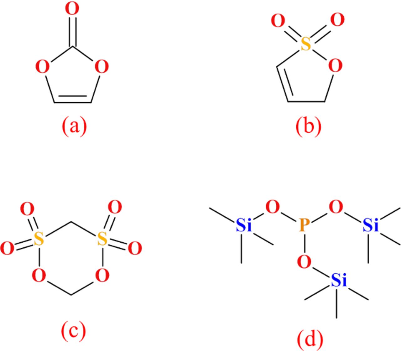
Figure 1. Chemical structures of the electrolyte additives used, (a) vinylene carbonate (VC), (b) prop-1-ene-1,3 sultone (PES), (c) methylene methanedisulfonate (MMDS) and (d) tris(trimethylsilyl) phosphite (TTSPi).
Pouch cells
Dry NMC442/graphite pouch cells (240 mAh) balanced for 4.7 V operation were obtained from Li-Fun Technology (Xinma Industry Zone, Golden Dragon Road, Tianyuan District, Zhuzhou City, Hunan Province, PRC, 412000).
All pouch cells were vacuum sealed without electrolyte in a dry room in China and then shipped to our laboratory in Canada. Before electrolyte filling, the cells were cut just below the heat seal and dried at 80°C under vacuum for 12 hours to remove any residual water. Then the cells were transferred immediately to an argon-filled glove box for filling and vacuum sealing. The NMC442/graphite pouch cells were filled with 0.9 g of electrolyte. After filling, cells were vacuum-sealed with a compact vacuum sealer (MSK-115A, MTI Corp.). First, cells were placed in a temperature box at 40.0 ± 0.1°C where they were held at 1.5 V for 24 hours, to allow for the completion of wetting. Then, the cells (called type-A cells) for probing impedance changes during cycling to different cut-off voltages were charged at 12 mA (C/20) to 3.5 V while the cells (called type-B cells) for long-term cycling (500 cycles at 45°C) were charged at 12 mA (C/20) to 4.4 V. After this step, all the cells were transferred and moved into the glove box, cut open to release any gas generated and then vacuum sealed again. Then the type-A cells were charged at 12 mA (C/20) to 4.5 V and moved into the glove box, cut open to release gas generated and then vacuum sealed. All the cells were then discharged at 12 mA (C/20) to 3.8 V for electrochemical impedance spectroscopy (EIS) testing before cycling.
Electrochemical impedance spectroscopy
EIS measurements were conducted on NMC442/graphite pouch cells before, during and also after cycling. Cells were charged or discharged to 3.8 V before they were moved to a 10.0 ± 0.1°C temperature box. Alternating current (AC) impedance spectra were collected with ten points per decade from 100 kHz to 10 mHz with a signal amplitude of 10 mV. A Biologic VMP-3 was used to collect this data.
Cycling tests
All the type-B cells were prepared for long-term cycling at 45.0 ± 0.5°C. The cells were charged and discharged at 100 mA (C/2.5) between 3.0 and 4.4 V using a Maccor Series 4000 (Tulsa, US) charger system. All the type-A cells were divided into 6 groups. Cells in the six different groups were cycled at 20 mA (C/12) between 2.8 V and different upper cut-off voltages (4.2, 4.3, 4.4, 4.5, 4.6, 4.7 V) using a Neware (Shenzhen, China) charger system at 40.0 ± 0.5°C. EIS measurements (always at 3.8 V and 10.0°C) were conducted on type-A cells after every 10 cycles. After the termination of the cycling tests, the volume of gas generated in all the cells was measured using Archimedes' principle using the ex-situ method described by Aiken et al.14
Results and Discussion
Figure 2 shows discharge capacity versus cycle number for NMC442/graphite pouch cells charged and discharged at C/12 between 2.8 V and different upper cut-off voltages at 40°C. The purple dashed lines indicate the position where EIS measurements were made. All the selected additives or additive blends have good capacity retention when the cut-off voltage is 4.2 V. The cells with 2% VC show worse capacity retention compared to the cells with 2% PES or "PES-211" when cut-off voltages are higher than 4.2 V, especially at 4.4 V. At 4.4 V, cells with 2% VC begin to fade after 20 cycles while cells with 2% PES or "PES-211" have good capacity retention. Only "PES-211" is beneficial for capacity retention when the cut-off voltage increases to 4.5 V but its effect is limited. All the cells fade dramatically during cycling up to 4.6 or 4.7 V demonstrating the difficulty of creating long-lived cells with cut-off potentials above 4.5 V.
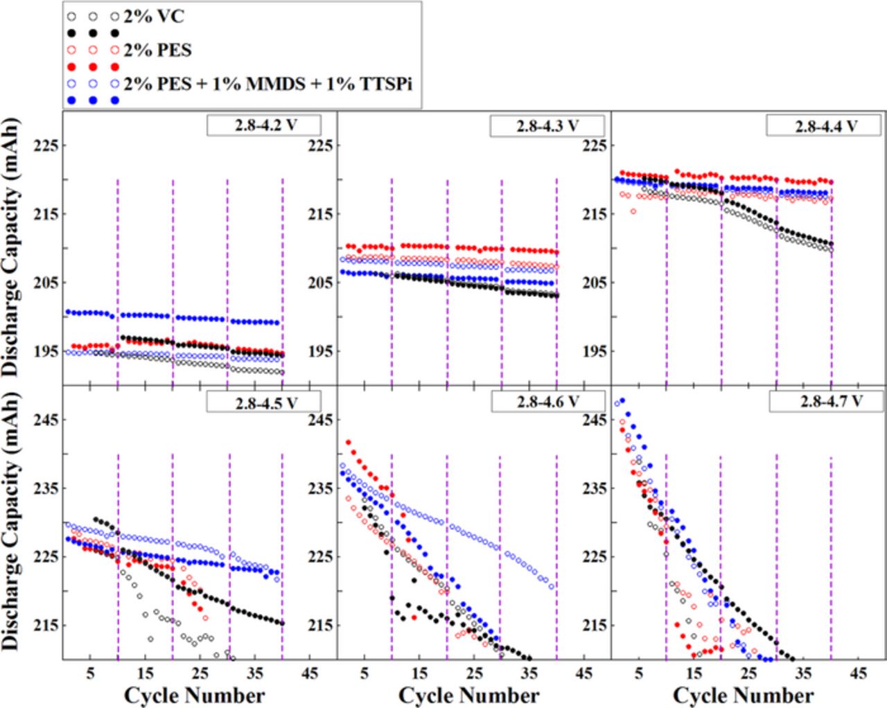
Figure 2. Discharge capacity versus cycle number for NMC442/graphite pouch cells charged and discharged at C/12 between 2.8 V and different cut-off voltages at 40°C. The vertical lines indicate when EIS measurements were taken.
Figure 3 shows Nyquist plots for NMC442/graphite pouch cells containing various additives or additive blends before cycling and after every 10 cycles to the six different cut-off voltages. The impedance spectra were measured at 3.8 V and at 10.0°C. The diameter of the semi-circle before cycling predominantly represents the sum of the charge-transfer resistances, Rct, at both the positive and negative electrodes. [Note: Our interpretation of the impedance spectra of Li-ion pouch cells follows others' previous work15,16 and Rct is the main contribution to the semi-circle (other contributions overlap with Rct)]. It is important to decrease or at least maintain the width of these semi-circles to ensure decent rate capability. The impedance of the 2% VC-containing pouch cells increases with cycle count when charged to different cut-off voltages, especially above 4.3 V. By contrast, cells with 2% PES and "PES-211" show relatively stable impedance with cycling up to 4.4 V and 4.5 V, respectively, and are vastly superior to cells with 2% VC. Although the impedance of "PES-211"-containing NMC442/graphite pouch cells is well-behaved during cycling to 4.5 V, the same cells show vast impedance growth with cycling when charged to 4.7 V, just like the cells with 2% VC and with 2% PES. This can explain why all cells in Figure 2 show poor capacity retention when cycled to 4.7 V. Some of the EIS spectra (e.g. 2% VC after cycling 10, 20, 30, 40 cycles between 2.8 and 4.4 V) change from one big semi-circle to two semi-circles as cycling proceeds. This has been determined by Petibon et al.17 to be caused by a huge increase in the impedance of the positive electrode during high voltage excursions when 2% VC is used. That is, the low frequency semicircle originates from the positive electrode while the high frequency semicircle originates predominantly from the negative electrode.17
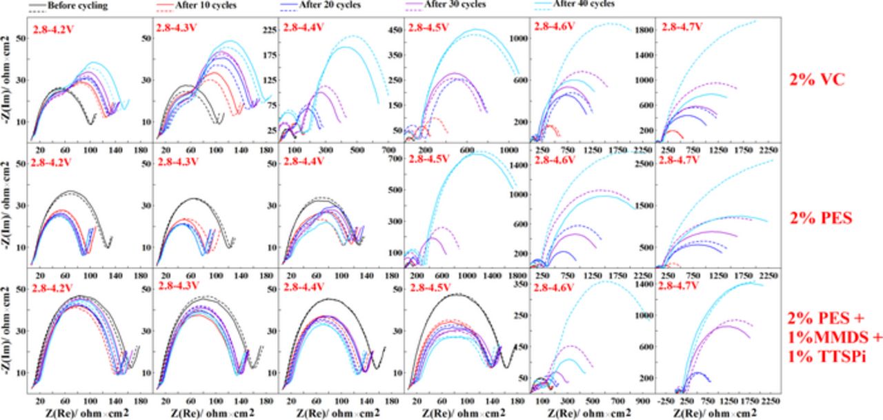
Figure 3. Nyquist plots for NMC442/graphite pouch cells containing the additives, 2% VC, 2% PES or "PES211" before cycling or after different cycle numbers at different cut-off voltages, as indicated. Please notice that the horizontal and vertical scales change in some panels when the cell impedance becomes large.
Figure 4 shows the amount of gas produced in NMC442/graphite pouch cells during the formation procedure and during cycling at 40°C between 2.8 V and various cut-off voltages. Each data point in Figure 4 represents the average value for two cells and the error bars are the standard deviation of the measured results. During formation, all additives or additive combination produce almost the same amount of gas when the cells are charged to 3.5 V. However, 2% VC-containing pouch cells produce more gas than the other cells when they are subsequently charged to 4.5 V. During cycling, all cells barely produce any measureable gas at cut-off voltages below 4.4 V while "PES-211"-containing cells produce more gas when the cut-off voltages are above 4.5 V.
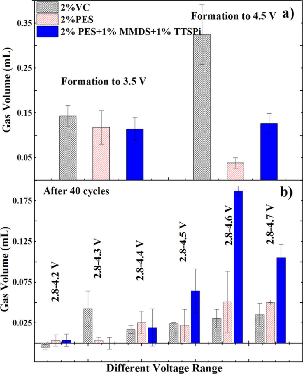
Figure 4. The amount of gas evolved in NMC442/graphite pouch cells during the formation procedure and after cycling at 40°C between 2.8 V and various cut-off voltages at 12 mA (C/20).
Since the impedance of pouch cells containing 2% PES or "PES-211" are stable during cycling to 4.4 V, cells with these additives were evaluated during long-term cycle testing at 45°C between 3.0 and 4.4 V at 100 mA (C/2.5). The pouch cells were cycled unclamped so any gas production during cycling would lead to a reduction or loss of stack pressure in the cells. Figure 5 shows the discharge capacity versus cycle number for NMC442/graphite pouch cells with 2% VC, 2% PES or "PES-211". The ternary additive combination shows a loss of only ∼ 15% capacity after 500 cycles and shows better capacity retention than cells with 2% VC or 2% PES.
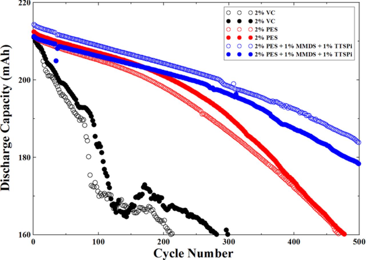
Figure 5. Discharge capacity versus cycle number for NMC442/graphite pouch cells containing the additives 2% VC, 2% PES or "PES-211". The cells were tested at 100 mA (C/2.5) between 3.0 V and 4.4 V at 45°C.
Figure 6 shows the amount of gas evolved during the long-term cycle testing at 45°C (described by Figure 5). The volume of the cells increases by less than 0.15 mL in all cases. Some of this expansion could come from electrode stack growth as well as from gas evolution.
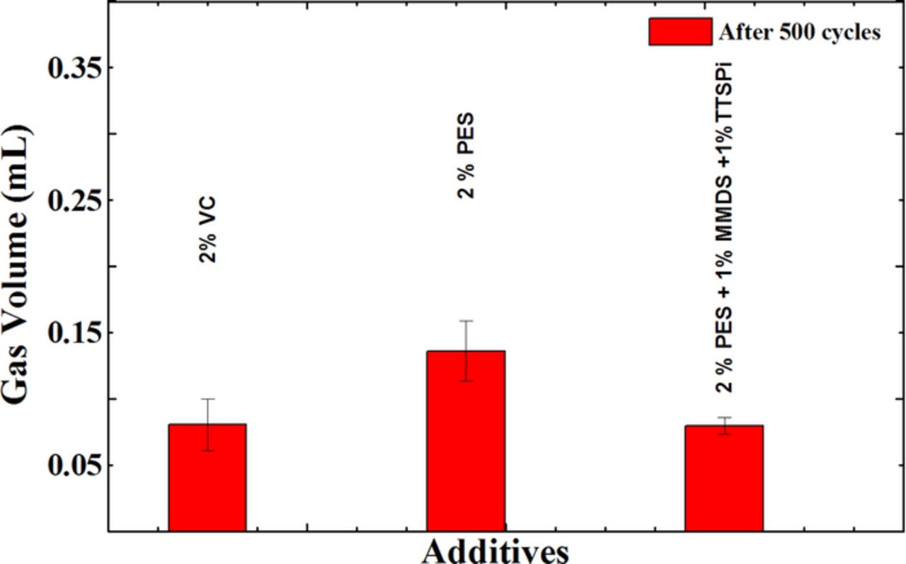
Figure 6. The amount of gas evolved in NMC442/graphite pouch cells during the long-term cycle testing at 45°C between 3.0 V and 4.4 V at 100 mA (C/2.5).
Figure 7 shows Nyquist plots for the NMC442/graphite pouch cells after the long-term cycling test shown in Figure 5. The impedance of the cells with 2% VC and with 2% PES increases during cycling while the impedance of the cells with "PES-211" actually decreases during long-term cycling. This indicates, again, the advantage of "PES-211" compared to both 2% VC and 2% PES.
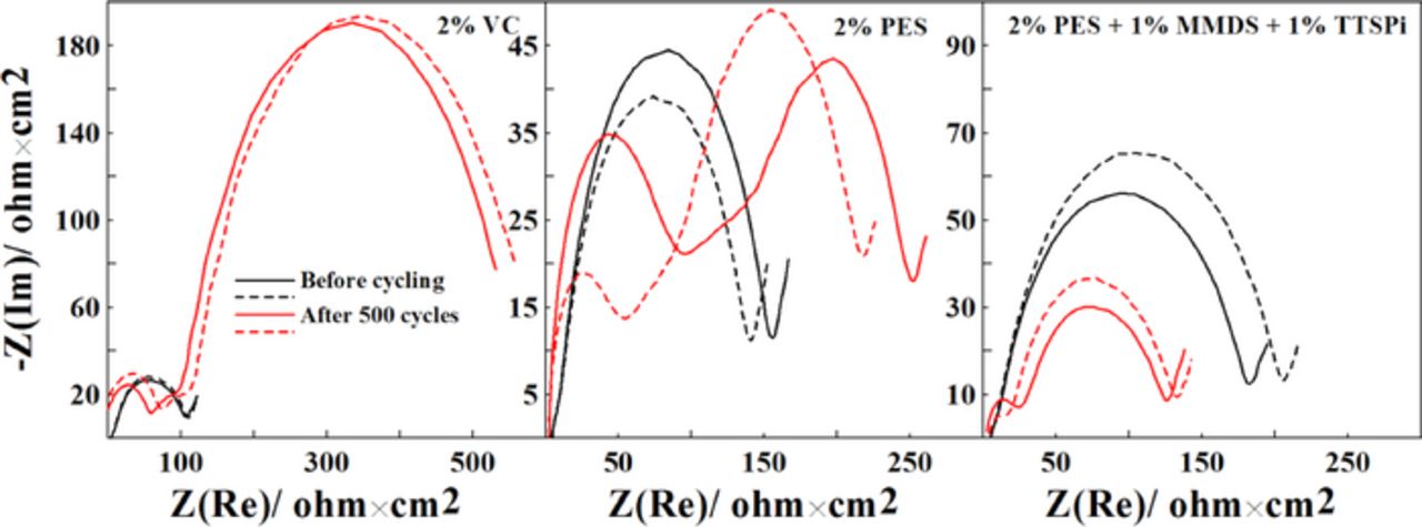
Figure 7. Nyquist plots for NMC442/graphite pouch cells containing 2% VC, 2% PES or "PES211" before and after the long-term cycling test at 45°C between 3.0 V and 4.4 V at 100 mA (C/2.5).
Conclusions
The single electrolyte additives 2% VC and 2% PES as well as the additive blend of "PES211" were studied in NMC442/graphite pouch cells. Cells with 2% VC showed dramatic impedance growth when cycled to 4.3 V and above. Cells with 2% PES showed stable impedance for 40 cycles at upper cut-off voltages of 4.4 V and below. Most impressive was the additive blend, "PES211", which yielded cells that had stable impedance for 40 cycles at upper cut-off potentials of 4.5 V and below.
A long-term cycling test was performed on the single additives or the additive blend. The test was made at 45°C between 3.0 and 4.4 V using currents corresponding to C/2.5. Cells with "PES-211" showed excellent capacity retention for 500 cycles compared to cells with 2% PES and 2% VC. In addition the impedance of the "PES211" cells actually decreased slightly during the 500 cycles. This suggests "PES211" is an excellent additive blend for NMC442/graphite cells targeted for 4.4 V operation. We hope that Li-ion battery manufacturers and researchers will study and use "PES211."
Acknowledgments
The authors thank NSERC, 3M Canada for the funding of this work under the auspices of the Industrial Research Chairs program.