Abstract
In this work we analyzed the phenomenon of quasi solid state (QSS) lithiation of sulfur-carbon (S/C) composite electrodes with sulfur confined in the micropores of carbon matrices based on our recent studies and data published in literature. We demonstrated that the existence of sulfur in the form of small molecules is not a necessary condition for the realization of QSS mechanism. QSS operation behavior was demonstrated both for carbons with small up to 1nm micropores and for carbons with larger pore size up to 2–3 nm. A key role in the operation of S/C electrodes via a QSS mechanism plays surface electrolyte interphase (SEI) which is formed on the surface of S/C composite during the initial discharge. The formation of SEI was supported by X-ray photoelectron spectroscopy and by scanning electron microscopy. Small pore size (up to 1 nm) of the carbon matrices has a positive effect on the cycling of S/C electrodes. A superior cycling performance for more than 3500 charge-discharge cycles was demonstrated for S/C composite electrodes based on carbons synthesized by carbonization of polyvinylidene dichloride (PVDC) resin.
Export citation and abstract BibTeX RIS

This is an open access article distributed under the terms of the Creative Commons Attribution 4.0 License (CC BY, http://creativecommons.org/licenses/by/4.0/), which permits unrestricted reuse of the work in any medium, provided the original work is properly cited.
In recent years lithium–sulfur batteries have been the subject of very intensive research due to the high theoretical specific capacity of sulfur cathodes (1672 mA h g−1) which is an order of magnitude higher than that of lithiated transition-metal oxides and phosphates cathode materials used in commercial Li-ion batteries (140–200 mA h g−1).1–6 This high capacity relates to the ability of sulfur atoms to accept two electrons resulting in the conversion of elemental sulfur to lithium sulfide (Li2S). Furthermore, sulfur is naturally abundant, environmentally friendly and relatively cheap.
Due to the low electrical conductivity of elementary sulfur the addition of conductive additives or the use of conductive host materials it is necessary to ensure good performance of sulfur electrodes. Besides, during the discharge process elemental sulfur S8 accepts electrons to give a chain of electroactive Li-polysulfides (Fig. 1a). The long-chain polysulfides Li2Sn (4 ≤ n ≤ 8) are soluble in commonly used ethereal solvents and diffuse freely throughout the cell to the anode side where they are chemically reduced. This phenomenon known as the shuttle effect presents one of the main problems of Li–S cells.7 The shuttle reactions prevent the possibility of extracting the full capacity of sulfur cathodes and lead to low Coulombic efficiency. Encapsulation of sulfur within activated carbons with high pores volume is one of the most effective approaches to mitigate the detrimental shuttle mechanism and stabilize composite sulfur cathodes during prolong cycling.8–10
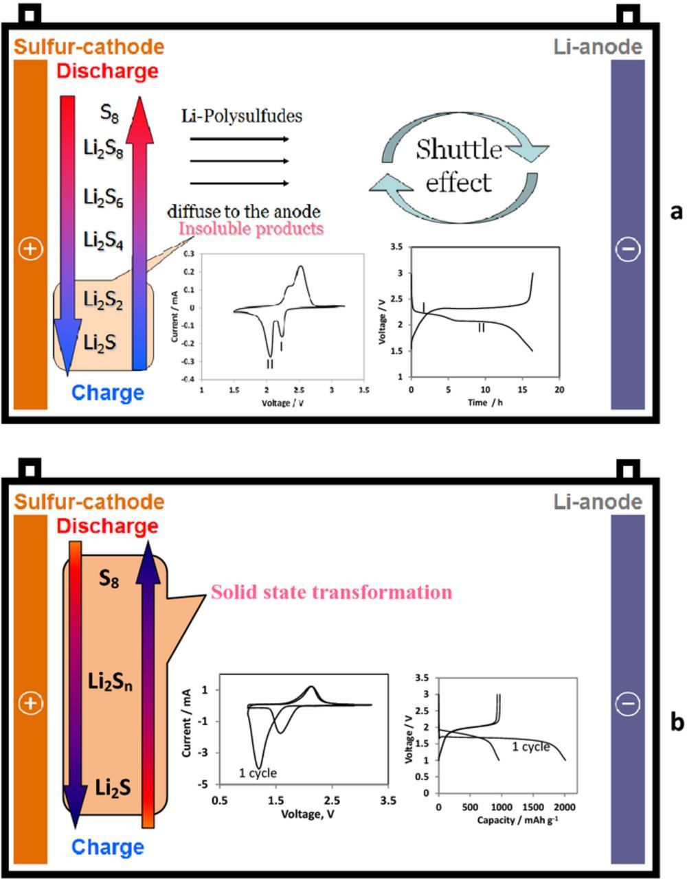
Figure 1. Schematic presentation of two reaction paths observed for Li-S cells with typical CV and galvanostatic responses: a) normally observed solid-liquid-solid reaction and b) quasi-solid-state reaction. Reproduced with permission from Ref. 6.
The typical cyclic voltammetry and galvanostatic charge-discharge curves of the Li-S cell with C/S encapsulated cathode are shown in Fig. 1a. Two peaks observed in the cathodic voltammetric response of sulfur electrodes correspond to two plateaus observed in the voltage profiles of the discharge processes of these cathodes upon galvanostatic (constant current) cycling.4
The first voltage plateau at ≈2.3 V relates to the reduction of the cyclic S8 to long chain lithium polysulfides (Li2Sn 4 < x ≤ 8) soluble in the electrolyte solution, and the following plateau around 2.1 V is associated with the further reduction of these polysulfides to Li2S2 and Li2S.4 This type of behavior is generally observed in ethereal electrolyte solutions. The great majority of publications on Li-S batteries are devoted to study and development of Li-S electrodes which behave according to this solid-liquid-solid reaction path.4,6,11,12
However, in several works another type of behavior of Li-S electrodes was described.13–40 This type of behavior schematically presented in Fig. 1b is generally observed for organic carbonate-based electrolyte solutions,13–22,24,25,27,31,33,35,36,39,40 as well as for bis(fluorosulfonyl)imide (FSI) anion-based ionic liquid electrolyte solutions.28,37,38 For this type of the operation of Li-S cells voltage profiles differ from those commonly measured for conventioanal Li–S composite electrodes and are characterized by a single galvanostatic charge/discharge voltage plateau observed around 2.0 V vs. Li/Li+. Correspondingly, only one reduction and oxidation peaks appear in the cyclic voltammograms of these unique sulfur electrodes. Besides, potential hysteresis in the initial cycles is always observed for these kinds of Li-S electrodes. It is remarkable that the voltage profiles measured with these types of cells with liquid electrolyte solutions are very similar to that of solid state Li-S cells26,41 and for sulfurized carbon electrodes with sulfur covalently bound onto the surface of carbon particles.18,42–44 In the case of liquid electrolytes Wang et al. proposed that this type of unique behavior (namely, the single plateau observation) relates to the reaction of Li ions after desolvation with sulfur encapsulated in the micropores under solvent deficient conditions and called this mechanism "quasi-solid-state reaction".15,45 In most cases this mechanism is observed for composite S/C electrodes with very narrow micropores which width is lower than 1 nm,14–16,19,20,22,23,28,40 but in some cases this type of operation was described also for larger pore size.13,29,37–39
Several explanations for this single-plateau behavior can be found in the literature.
- (1)The formation of special complexes of the sulfur embedded in the fine pores with carbon or surface-bound oxygen.8,14 The hysteresis observed in the initial cycles according to this concept is assigned to the suggestion that electrochemical reaction between sulfur and lithium during discharge needs an additional energy to break such complexes, leading to a high electrochemical polarization and a lower discharge voltage compared to electrodes comprising pure sulfur. After lithium extraction, the complexes will reform but with a lower absorbing energy and the cell exhibits a higher discharge voltage after its first cycle.
- (2)Desolvation of the solvated Li ions ions by the micropores which pore size is below 1 nm may play a critical role, since solvated ions tend to be desolvated in micropores with a size close to the ion size.15,20,21,45 The reduction of sulfur still produces polysulfides as intermediates, but the polysulfides remain in the pores instead of being dissolved. Li desolvation prevents or slows down the dissolution of polysulfides as the solvent concentration is very low or close to zero in the micropores. Thus, according to this concept the pore size is the key factor that facilitates the desolvation process and ensures quasi-solid-state reaction of the sulfur under solvent-deficient conditions.15,45
- (3)Small micropores (∼0.7 nm) can accommodate short chains of sulfur in low molecular forms.16,19,22,23,31–33 According to this view, cyclo-S5–8 with at least two dimensions larger than 0.5 nm cannot exist inside micropores, while small S2–4 molecules with at least one dimension less than 0.5 nm can be hosted therein. Thus, long-chain lithium polysulfides, which usually attack carbonate solvents, are not formed in the cycling process. Instead, a direct solid-solid transition takes place from S2 to S4 - Li2S during discharge. During charging, the small size of the micropores would allow only the re-formation of S2 to S4 instead of S8, hence ensuring the reversibility of the reaction. In this works, however, the origin of short chain sulfur molecules inside the micropores is not explained in a conclusive way. (The details are presented in the next section.)
- (4)The realization of quasi-solid-state reaction is governed by the formation of solid electrolyte interphase (SEI) on the surface of sulfur cathodes during the initial discharge.29,38–40 Surface films when formed, force desolvation of Li ions that migrate through them, and hence, induce possible quasi-solid-state operation of the cells. Voltage hysteresis and irreversible capacity observed during the first cycles are the result of side reactions of electrolyte solution components with Li2Sn leading to SEI formation on the surface of S/C composite electrodes, what prevents further irreversible reactions. This scenario was observed also for porous carbons with pores size up to 2–3 nm29,38,39 which can accommodate not only S2–4, but also S5–8 and sulfur molecules Sn (n > 8). Hence, the small molecules concept is not necessary for the explanation of QSS behavior of S/C cathodes.
Despite of some inconsistencies, the small sulfur molecules approach for the explanation of QSS mechanism dominant in the literature.4,16,19,22,23,31–33,46–48 In the recent works21,47 it was concluded that deeper insight into the electrochemical reactions pathways and interactions of the low molecular allotropes of sulfur S2–4 is urgently needed.
In the present work we discuss and critically review the preceding concepts on the basis of analysis of the literature and recent results obtained during our study of Li-S systems.
Preparation Conditions of S/C Composites and Sulfur Confinement in Microporos Carbons
W. Zhang et al.36 cast doubt on a possible existence of sulfur in the form of small molecules in narrow micropores. The authors showed that S/C composite electrodes demonstrate both types of behavior presented in Fig. 1 in two different electrolyte solutions. In carbonate electrolyte solution (LiPF6/PC-EC-DEC) they observed one plateau characteristic of a solid state behavior of sulfur composite cathodes; whereas in ethereal electrolyte solution (LiTFSI/DOL-DME) normal two plateaus sold-liquid-solid behavior was detected. This result indicates that the embedded sulfur in the micropores of the carbon exists mainly as S8 molecules (S/C composite was prepared at 400°C). The authors argue that the micropores within the carbon with narrow pore size distribution of ∼1 nm may be wide enough for accommodating S8 molecules. They also claim that even if the original absorbates in the carbon matrix are small S4 and S2 molecules formed during electrodes preparation (by the S vapor transfer process), their relatively high energy state should drive them to recombine, forming more stable S8 molecules inside the micropores after cooling down to room temperature.
In Ref. 17,22 appearance of only one plateau solid state behavior is assigned to new sulfur chemistry of short chain sulfur molecules confined in micropores with a narrow pore width range around 0.5 nm. Wang et al. heated S/C composites to 600°C during their preparation suggesting that at this temperature the elemental sulfur (S8) dissociates into S2 in the gas phase. According to Ref. 49–51, at 600°C, sulfur gas possesses a significant fraction of S6 (58.8%) and only 16.4% S exists as S2 molecules, and in Ref. 47 the authors hold that from 550°C S2–4 molecules start prevailing.
However, in the majority of works in which the authors assigned the QSS behavior to the formation of small sulfur molecules, the preparation of S/C composites was carried out by melt infiltration at temperatures of about 155°C, at the point of minimal viscosity of elemental sulfur melt.14,16,19,23,33 It is also known that between the its melting (119°C) and boiling points (293°C), the molten sulfur is present in the form of equilibrium of various sulfur species (Sn) with n ranging from 5 to 33.42 According to Ref. 49–51, at temperatures <250°C a major fraction of the elemental sulfur vapor is in the form of S6-S8. Composition of the gaseous sulfur at 200°C is 76.5% of S8 rings and 23.5% of S6 rings.49,52
Thus, considering that one plateau QSS behavior was observed for S/C composite prepared at different temperatures, ranging from 155 to 600°C, including the temperatures at which short chain sulfur molecules exist with extremely low concentration, one can conclude that this type of electrochemical response is not necessarily connected to the existence of small sulfur molecules only within the S/C matrices.
Recently, Fu et al.21 relying on the literature data and their own calculations concluded that the majority of sulfur in the sub-nano confinement is S8 molecule. They observed a one plateau behavior for C/S composites prepared at a temperature ≤200°C. The authors argue that at these experimental conditions the only scenarios when the majority of pores filled with small sulfur molecules are (1) infusing with extremely large amount of sulfur, which is obviously no true in their case; or (2) generating small sulfur molecules within the pores, of which the only enabling force could be some surface adsorption energy that was high enough to "break off" a few (2 to 4) bonded sulfur atoms from the main molecule and maintaining them as small molecules. In other words, the adsorption energy has to be equivalent to the thermal energy to generate high concentration of small sulfur molecules in vapor phase, which is obviously not the case either.
In our recent work,40 in which S/C composite electrodes were prepared at 200°C from PVDC derived carbon with pores whose width lower 1nm, we also observed one plateau QSS behavior in alkyl carbonates based electrolyte solutions. It is known that PVDC-derived carbon possesses narrow slit shape pores with pore width distribution of 0.5–1 nm.53,54 Thus, although according to cumulative pore volume distribution calculated by DFT, the pore width of most of the pores is less than 1 nm, slit shape pores may be long enough to accommodate not only small sulfur molecules but also S8 rings and polymeric sulfur molecules which exist at temperature of preparation of these S/C composites.51,52
Fig. 2 schematically presents an infiltration of S8 rings into the slit shape pores of a carbon matrix. It is seen, that these molecules could be accommodated inside such pores when they are properly oriented near the pores entrance. It is known, that slit-shaped pores of carbons possess molecular sieving properties and they are able to accommodate flat molecules such as benzene, naphthalene and other aromatic molecules, but not more bulky molecules.55 S8 rings resemble in their geometry aromatic carbonaceous molecules. Thereby, we can assume that they can be easily adsorbed in to the carbons possessing slit-shaped pores.
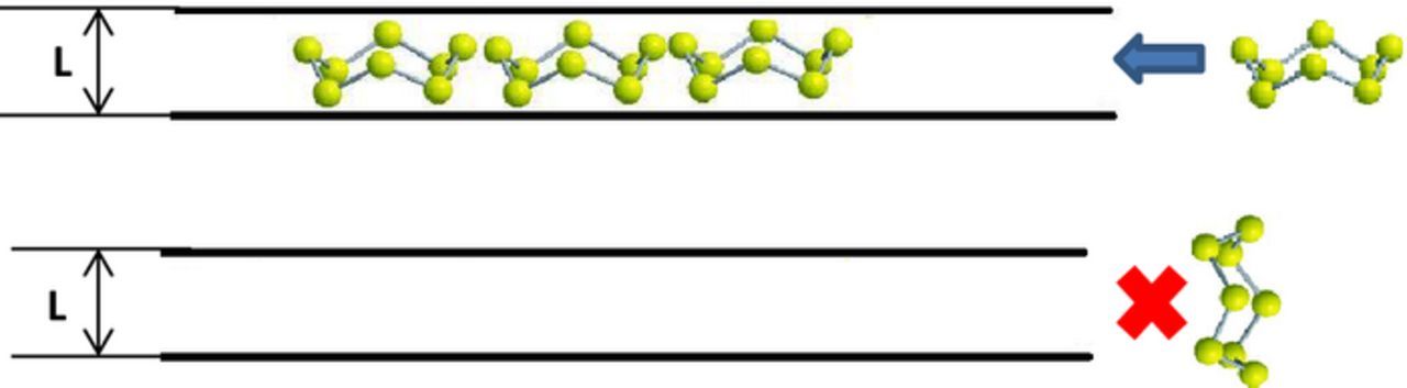
Figure 2. Accommodation of S8 molecules between two layers of carbon atoms in slit shape pores.
Sub-nano Confinement of Sulfur in Carbon Matrix is not a Necessary Condition for the Existence of QSS Mechanism for Sulfur Reduction in Li-S Cells.
As we mentioned in the previous section, QSS behavior of S/C composite cathodes was observed not only for microporous carbon hosts with sub-nano pores but also for carbons with wider pores size.13,29,37–39
In the present section we demonstrate the possibility of QSS type of sulfur cathodes operation both for carbon with pore width lower than 1 nm and for carbon having more than 50% of their pores wider than 1 nm.
SEM images of two different types of carbon powders comprising micronic particles are shown in Figs. 3a and 3b. The first one, denoted as AC1, is a commercial activated carbon, and the second one, PVDC derived carbon (PVDCDC) was synthesized by carbonization of PVDC powder. The details of the preparation procedure of PVDCDC, as well as characterization of S/AC1 and S/PVDCDC composites are described in the Supplementary Information file (Fig. S1). XRD patterns of the sulfur powder exhibit its crystalline structure (Fig. S1-a). No crystalline sulfur peaks were detected in the sulfur-AC1 and sulfur-PVDCDC composite powders, indicating the absence of free sulfur not impregnated in the pores.
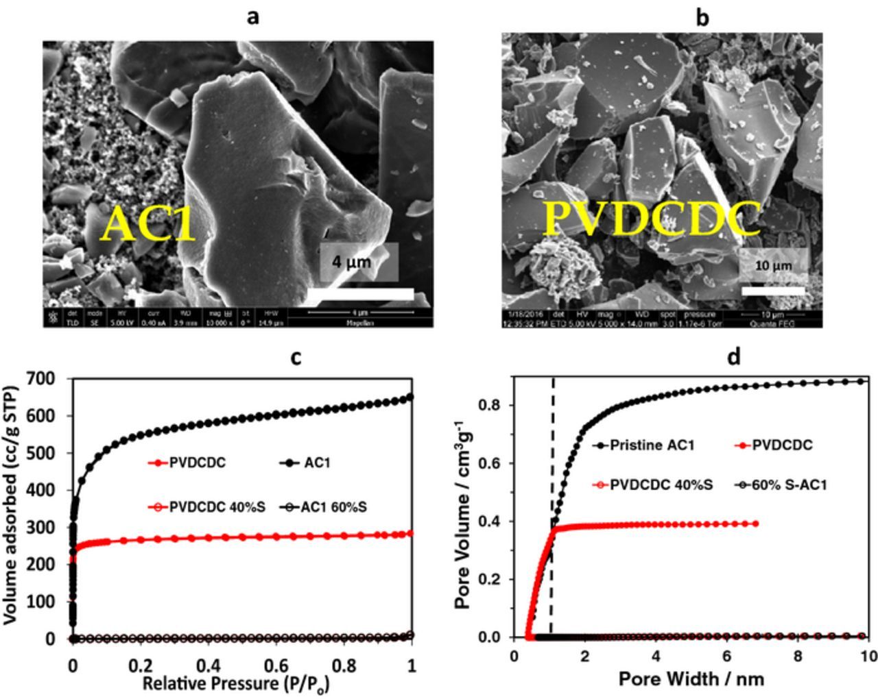
Figure 3. SEM images of AC1 (a) and PVDCDC (b), N2 adsorption/desorption isotherms measured at 77 K (c) and cumulative pore volume distribution calculated by DFT (d) of AC1 and AC1 impregnated with 60 wt% of sulfur (black curves) and PVDCDC powder and PVDCDC impregnated wiμth 40 wt% of sulfur (red curves). (a) Reproduced with permission from Ref. 38. (b) Reproduced with permission from Ref. 40.
N2 adsorption/desorption isotherms measured at 77 K and cumulative pore volume distribution calculated by DFT are shown in Figs. 3c and 3d, respectively. The type I isotherms obtained for both AC1 and PVDCDC pristine powders indicate their microporous structure. As is seen from Fig. 3d, for AC1 more than 50% of the pores are wider higher than 1 nm. In turn, PVDCDC possesses the micropores with pore width lower than 1 nm. The total specific pores volume of AC1 powder is around 1 cc/g and for PVDCDC powder is 0.43 cc/g. After the impregnation of AC1 with 60 wt% S and PVDCDC with 40 wt% S the total pores volume decreased by two orders of magnitude.
The BET specific surface area of AC1 and PVDCDC carbon powders calculated from nitrogen adsorption isotherms was about 2100 m2/g and 1000 m2/g, respectively. For AC1/S and PVDCDC/S composite powders BET specific surface area comprises 3.9 m2/g and 5.2 m2/g, respectively. Thus, after the infiltration of 60% S into AC1 carbon powder and 40% S into PVDCDC carbon powder there were no more pores accessible for N2.
Galvanostatic cycling performance of Li–S cells with S/C composite cathodes prepared with both carbon powders are presented in Fig. 4 and Fig. 5, related to the use of two different electrolyte solutions: LiFSI/MPPFSI and in LiPF6/FEC/DMC solutions respectively. It is remarkable, that both AC1/S and PVDCDC/S composite cathodes show in IL and organic carbonate electrolyte solutions voltage profiles typical for a quasi-solid state mechanism of the S-C cathodes with a single discharge and charge plateaus. Maximal specific charge capacity of 1200 mA h g−1 at 30°C (Fig. 4a) and 1400 mA h g−1 at 60°C37,38 measured with the LiFSI/MPPFSI IL electrolyte suggests that not only sulfur confined in pores smaller than 1 nm, but also sulfur impregnated in the pores with up to 2–3 nm width may operate according QSS mechanism. Hence, confinement of sulfur in sub-nanometric pores is not a necessary condition for the realization of this type of behavior. In contrast to IL electrolyte solution, in the carbonate based electrolyte solution specific capacity of AC1/S composite electrodes is lower than that of PVDCDC/S composite electrodes. Possible reason for this observation may be that not all sulfur confined in the pores larger the 1 nm participates in reversible lithiation-delithiation process. Obviously, the smaller pores facilitate the formation of surface films and ensure their better adhesion to carbon matrix compared to larger pores. Effective surface films make easier desolvation of Li ions, which plays a key role for QQS reaction.15,20,21,45
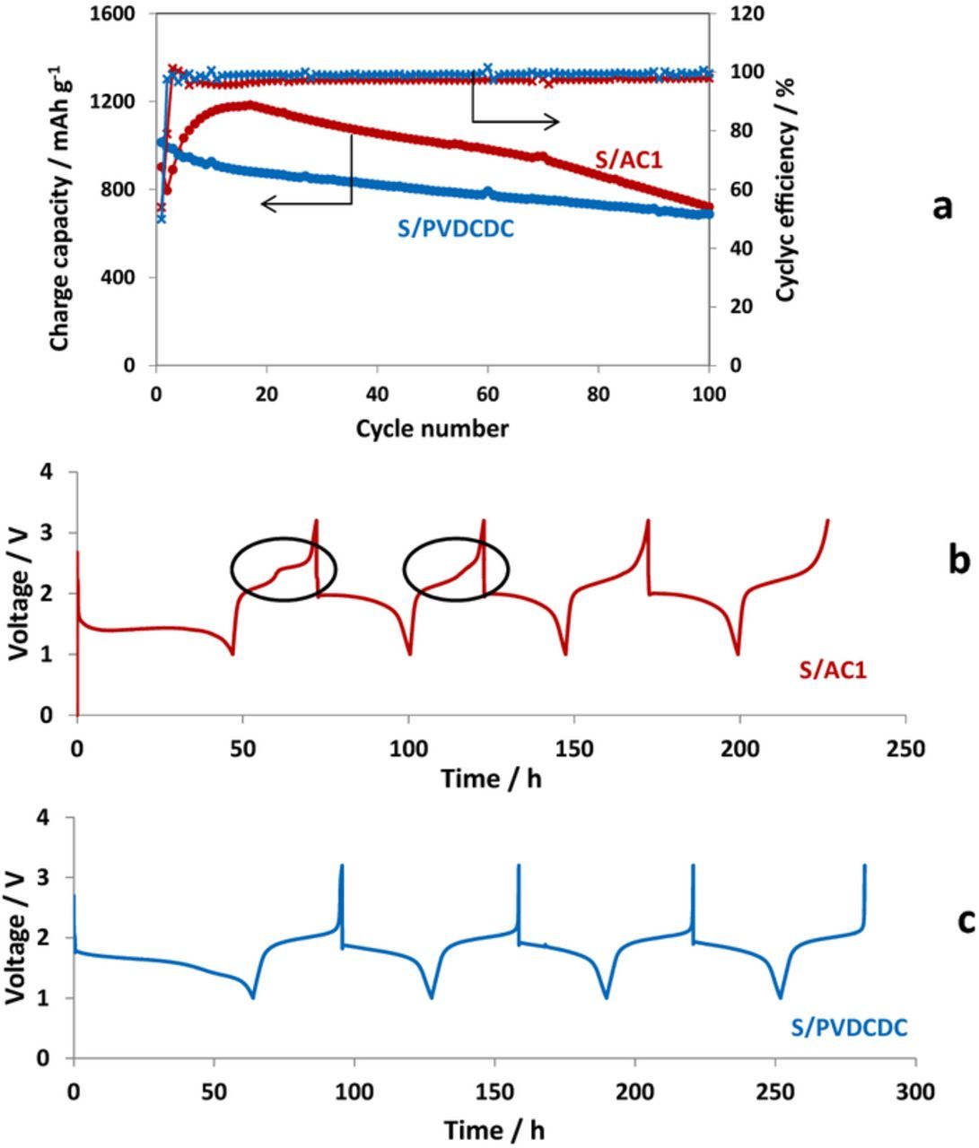
Figure 4. Galvanostatic charge-discharge curves obtained for Li-S cells with S/AC1 (red curves) and S/PVDCDC (blue curves) cathodes (a) and voltage profile measured during the first 4 cycles for S/AC1 (b) and S/PVDCDC (c) electrodes in 0.5 M LiFSI/MPP FSI electrolyte solution at a current rate of 30 mAg−1. 30°C.
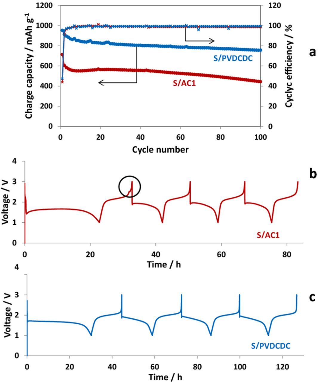
Figure 5. Galvanostatic charge-discharge curves obtained for Li-S cells with S/AC1 (red curves) and S/PVDCDC (blue curves) cathodes (a) and voltage profile measured during the first 4 cycles for S/AC1 (b) and S/PVDCDC (c) electrodes in 1 M LiPF6/FEC/DMC electrolyte solution at a current rate of 70 mAg−1. 30°C.
Interestingly, in the case of S/C cathodes prepared with AC1 an additional higher voltage plateau was observed during two initial charges with the IL electrolyte solution (Fig. 4b). For the alkyl carbonates based electrolyte solution this plateau is very short and was detected only upon the first charging process (Fig. 5b). This observation is obviously related to the fact that AC1 carbon possesses wider pores size distribution than PVDCDC carbon with both sub-nano and larger micropores (>1 nm). For large pores the formation of protective SEI (which fully prevents contact between the sulfur confined in the pores with the electrolyte solutions) requires longer cycling time. It is seen that using the electrolyte solution based on alkyl carbonates including FEC, ensures faster formation of perfect SEI compared to the IL based electrolyte solution.
An increase in the reversible capacity observed for S/AC1 composite cathodes during the initial 15 cycles in the IL based electrolyte solution (Fig. 4a) may be assigned to the fragmentation of S/C particles due to the volume expansion during the formation of Li2Sn species. Indeed, cracking of S/AC1 particles is clearly seen in SEM images of composite cathodes that were cycled in the IL based solution (yellow arrows in Fig. 6a and 6b). It is interesting that S/PVDCDC electrodes preserve their integrity without any visible cracks on their surface (Figs. 6c and 6d). More stable cycling behavior of the S/PVDCDC composite cathodes in IL based solutions and their higher cycling efficiency compared to that of S/AC1 cathodes (Fig. 4a) are in line with this observation.
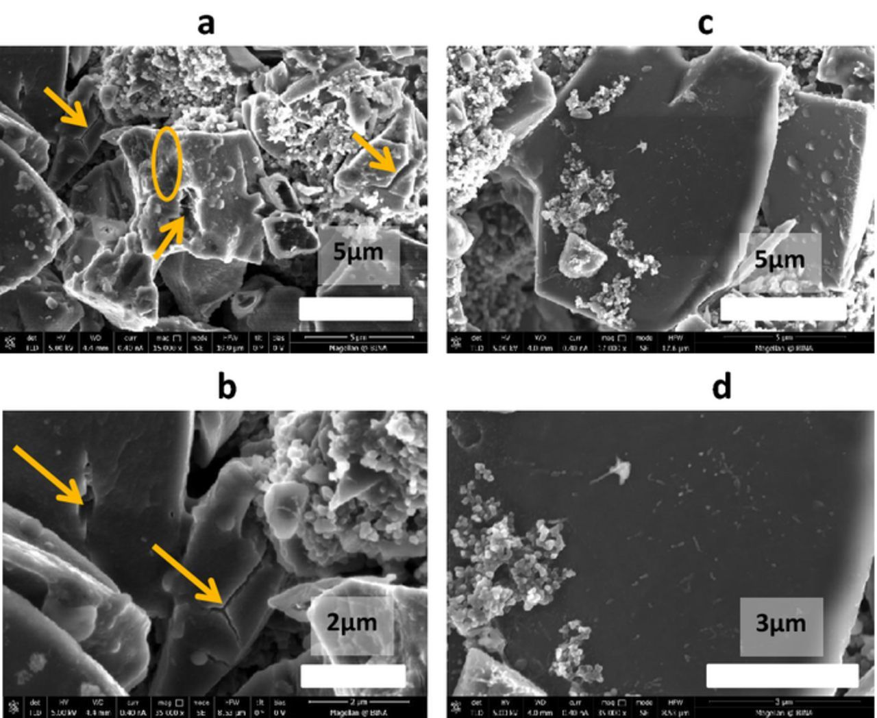
Figure 6. SEM images of S/AC1 (a, b) and S/PVDCDC (c, d) composite electrodes after 100 cycles in 0.5 M LiFSI/MPP FSI electrolyte solution. 30°C. (b) Reproduced with permission from Ref. 38.
In the alkyl carbonates based electrolyte solution both types of composite electrodes demonstrate very high efficiency of about 100% indicating the existence of highly protective SEI which is formed in the FEC-containing electrolyte solution. S/PVDCDC composite cathodes demonstrated much more stable behavior with higher reversible specific capacity than S/AC1 (Fig. 5a).
The combination of electrolyte solution containing FEC with S/PVDCDC composite electrodes results in excellent cycling performance of Li-S cells, demonstrating thousands of cycles without marked capacity fading and excellent rate capability (Fig. 7). A very stable cycling for more than 3000 cycles without any capacity fading during more than 1000 cycles (600 mAh/g sulfur) was usually observed at a current density of 1.04 A/g (Figure 7a). After that, a slow monotonous capacity fading was observed during about 2000 cycles and after 3000 cycles the reversible specific capacity of the cell comprised about 450 mAh/g-sulfur. A stepwise lowering of the current density from 1.04 A/g down to 0.065 A/g led to an increase in the reversible capacity provided by S/C electrode up to about 965 mAh/g-sulfur (Figs. 7a and 7b). It is notable, that after cycling during more than 3000 cycles at high current density, the S/PVDCDC electrodes still demonstrates at low rates the same specific capacity as measured for the fresh electrodes at the beginning of their cycle life (using the same current density, Figs. 7b and 7c). This result testifies that S/C electrodes may be extremely stable during prolonged cycling and are capable to deliver high capacity, depending on the current density. The cell disassembled after 3465 cycles was almost dry. Thus, the capacity fading observed during prolonged cycling of S/PVDCDC electrodes is probably relates to electrolyte solution depletion. It is remarkable that these cells possess an excellent rate capability considering that the composite S/PVDCDC electrodes consist of fairly large particles up to dozens of microns (Figure 3b). Hence, reduction of the particles size should further improve the rate capability of these electrodes.
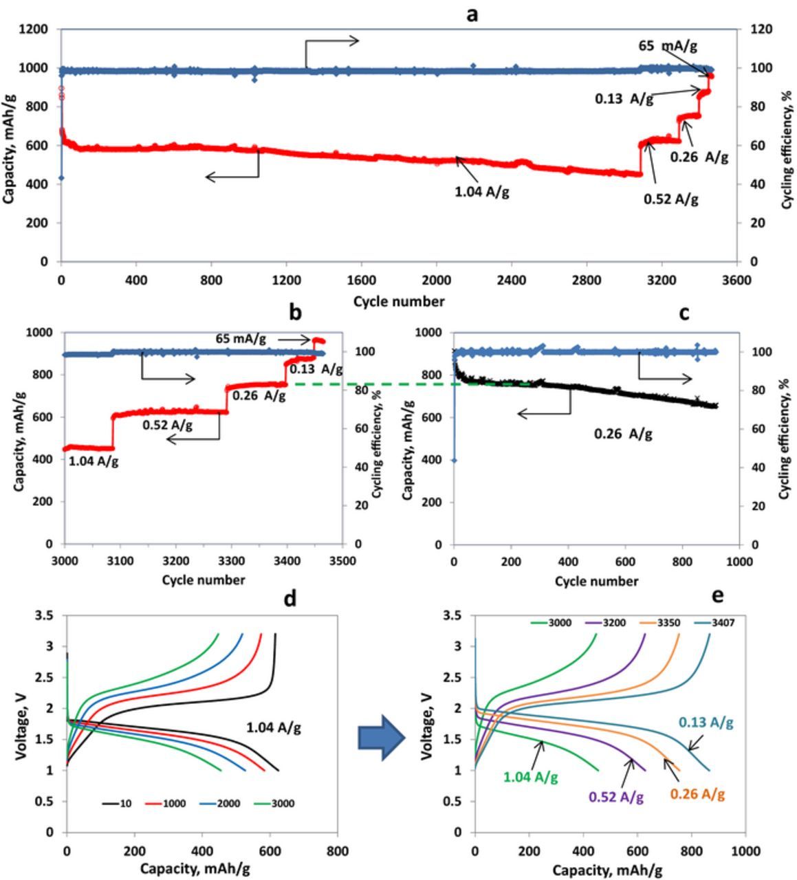
Figure 7. (a, b) Charge capacity and cycling efficiency vs. cycle number curves of Li/S-PVDCDC cell (sulfur loading 1mg) cycled at different current densities, as indicated; (c) Charge capacity and cycling efficiency vs. cycle number curves of Li/S-PVDCDC cell (sulfur loading 1.2 mg) cycled at current density of 0.26 A/g; (d) Voltage profiles of S-PVDCDC/Li cell measured at cycles 10, 1000, 2000 and 3000, as indicated, at a current density of 1.04 A/g; (e) Voltage profiles of S-PVDCDC/Li cell measured at cycles 3000, 3200, 3350 and 3407 at different current densities, as indicated. Electrolyte solution 1 M LiPF6/FEC/DMC, 30°C.
Thus, here we demonstrate by comparison of cycling behavior of two S/C composite cathodes that small pore size of the carbon matrix may have positive effect on QSS cycling results, but is not necessary for the realization of QSS mechanism.
Effect of the Electrolyte Solution Composition, Cycling Conditions and Sulfur Loading in S/C Composite Electrodes Operating in the QSS Mechanism, on the Electrochemical Performance of Li-S Cells
For all examples of QSS reactions of sulfur cathodes described in the literature the voltage profiles of the cells measured in the 1st galvanostatic cycle differ substantially from that measured in subsequent cycles. The same phenomenon is observed in all cases described in this work (Figs. 4, 5). One can observe that during the initial discharge process, the potential plateau at the first discharge is much longer and observed at lower voltage than the similar potential plateaus measured in the following cycles. Notice that in many works in which QSS mechanism was observed the explanation of the phenomenon of voltage hysteresis was ambiguous.14–21,25,31 As we mentioned above, in Ref. 14 it was suggested that voltage hysteresis is the result of the formation of special complexes of the sulfur embedded in the fine pores with carbon or surface-bound oxygen. In Ref. 25 voltage hysteresis is assigned to the release of strain/stress in the C/S composite materials in the first cycle. We anticipate that the low voltage plateau in the first discharge process corresponds to the formation of protective surface films on the S/C cathodes, and this process is responsible for voltage hysteresis phenomenon. This view may be supported by voltage profiles measured for S/AC1 composite electrodes with stepwise decrease in discharge cutoff value.39 As is seen in Fig. 8a, the reversible activity of S/AC1 electrodes in alkyl carbonates based electrolyte solutions was achieved only when the discharge cutoff value became lower than 1.5 V. The long discharge plateau observed after this activation process relates to irreversible SEI formation and reversible sulfur reduction to short chain polysulfides. Surface films which are formed during this necessary pretreatment step prevent direct contact of the electrolyte solution with the reactive LiSn products of sulfur reduction. As a result of SEI formation, a reversible cycling with voltage profiles showing only one discharge and one charge plateaus is observed with potential hysteresis typical for the "quasi-solid-state" mechanism of composite S/C electrodes. In addition, the behavior of S/C cathodes via a QSS reaction may depend on the potential applied during their first discharge process. For example,38 S/AC1 electrodes do not exhibit any activity in PC-based electrolyte solutions when cycled with a lower cut off voltage of 1 V (Fig. 8b, black curve). However, when the discharge of these electrodes was performed down to 0.5 V, a reversible cycling with QSS type behavior was observed (Fig. 8b, red curve). The same phenomenon was observed for TFSI-based IL electrolyte solution (Fig. 8c). Hence, in these solutions, application of lower potentials is required to drive reduction processes that fem protective, SEI type surface films. These examples strongly support our conclusion that not the structure of the carbon matrices but rather the possible formation of protective surface films plays the key role in the operation of S/C electrodes via a quasi-solid-state mechanism.
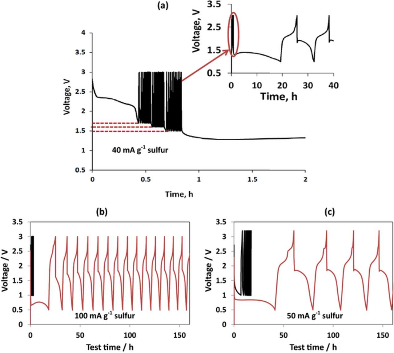
Figure 8. Galvanostatic voltage profile of Li-S/AC1 cells measured during cycling with different discharge cut off voltage (a) in 1 M LiPF6/FEC/DMC; (b) in 1 M LiPF6 in PC and (c) in 0.5 M LiTFSI in BMP TFSI 30°C. (a) Reproduced with permission from Ref. 39. (b) and (c) Reproduced with permission from Ref. 38.
The following examples provide further support for this conclusion. In solutions based on propylene carbonate (PC), S/AC1 electrodes cycled with lower cut off voltage equal to 1.5 V fail due to the reactions of Li polysulfides with the carbonate molecules (Fig. 9a).38 However, after the pretreatment during by several repeated cycles in the IL electrolyte solution (Fig. 9b) the electrodes transferred to the PC-based electrolyte solution demonstrated a stable cycling in the same voltage range with voltage profiles showing only one plateau (Fig. 9c). Alternatively, normal voltage profiles with two plateaus usually observed with the ethereal solutions (Fig. 9d) appeared when S/AC1 electrodes pretreated in the IL electrolyte solution (Fig. 9e) were transferred to ethereal solutions (Fig. 9f).This means that the SEI type surface films formed in the IL electrolyte solution (by the pretreatment) are not stable during cycling in 1 M LiFSI/DOL/DME solutions, because the surface species dissolve in them. It should be remarked that for S/AC1 composite cathodes two different types of behavior were observed in different electrolyte solutions, as in the case reported by W. Zhang et al.36 This observation strongly confirms that elemental sulfur is confined in the pores of the described activated carbons in its normal state, and this fact does not prevent the possibility of QSS behavior of S/C composite cathodes prepared with these carbons in proper electrolyte solutions.
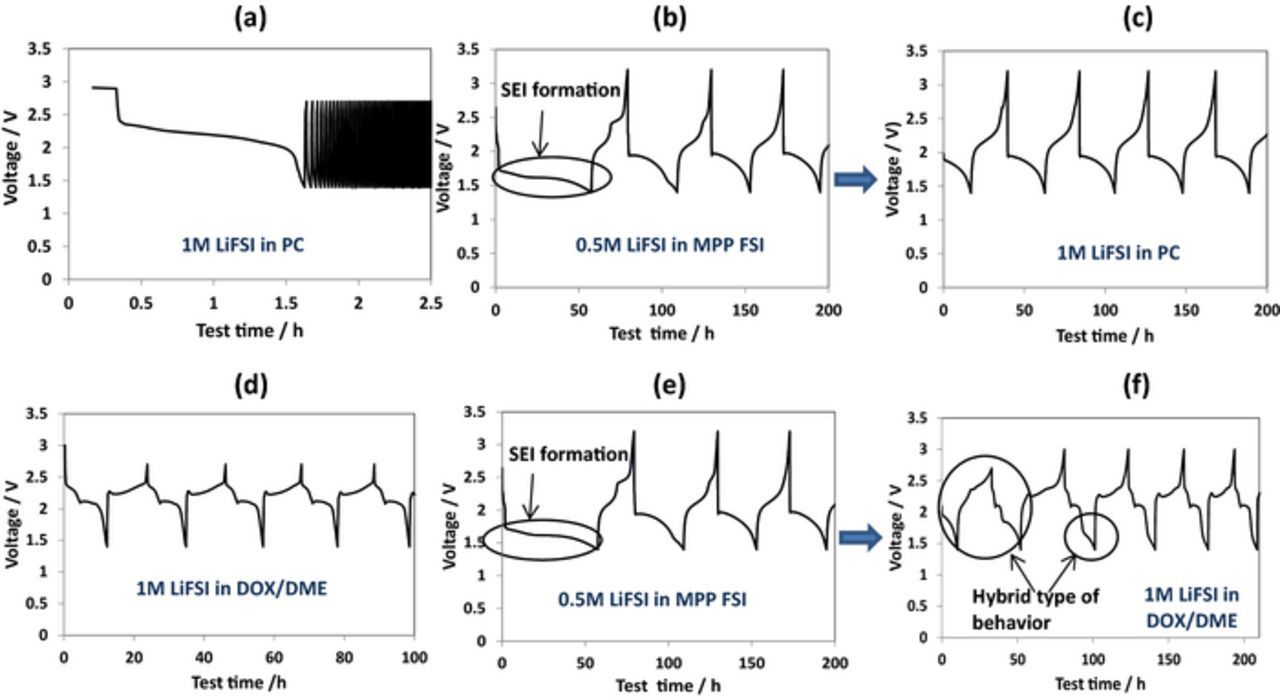
Figure 9. Voltage profiles measured for composite S/AC1 electrodes in PC-based and ethereal electrolytes before and after the pretreatment step in IL electrolyte. a) Fresh electrode cycled in 1 M LiFSI in PC, b) Fresh electrode cycled in 0.5 M LiFSI in MPP FSI and c) transferred after that to the new cell with fresh Li counter electrode and 1 M Li FSI in PC electrolyte solution, d) Fresh electrode cycled in 1 M LiFSI in DOX/DME, e) Fresh electrode cycled in 0.5 M LiFSI in MPP FSI and f) transferred after that to the new cell with fresh Li counter electrode and 1 M LiFSI in DOX/DME electrolyte solution. Current density 50 μA g−1 sulfur, 30°C. Reproduced with permission from Ref. 38.
Finally, the pronounced effect of sulfur loading in S/C composite electrodes on their cycling provides additional argument in support of the conclusion that SEI formation is the major promoter of QSS reaction path in Li-S cells (Fig. 10).38 It is seen that as the sulfur loading was higher, so the cycling behavior observed was better and the irreversible capacity measured in the initial galvanostatic cycle was lower as well (Fig. 10, inset). It is clear that as the sulfur loading is higher, the lower is the surface area of the sulfur exposed to the electrolyte solution and a lower portion of the sulfur is consumed for SEI formation (via reactions of LiSn moieties with solution species).
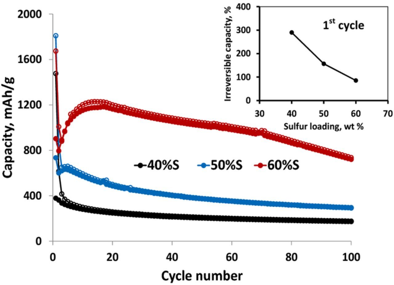
Figure 10. Galvanostatic charge-discharge curves and initial irreversible capacity vs. cycle number (inset) measured as a function of sulfur loading in S-AC1 composite cathodes in 0.5 M LiFSI in MPP FSI electrolyte solution. Current density 50 mA g−1. 30°C. Inset reproduced with permission from Ref. 38.
Direct Evidences of SEI Formation on S/C Composite Cathodes by XPS and Electron Microscopy
In order to confirm the formation of SEI on the surface of the S/C composite electrodes explored in the studies described by this paper, we performed SEM and XPS analysis of the cycled electrodes. Fig. 11 shows XPS F 1s, C1s and S 2p spectra and SEM images of pristine S/PVDCDC electrode and the same electrode after being cycled in LiPF6/FEC/DMC electrolyte solution.40 The C 1s spectrum collected from the pristine electrodes (upper curves) contains a peak at 285 eV related to carbon and two peaks attributed to CH2 and CF2 groups of PVdF with a corresponding peak at 688.6 eV in the F 1s spectrum of this electrode. Doublet in S 2p region with energy separation between the two peaks of about 1.2 eV is assigned to elemental sulfur (Fig. 11a).56 The formation of the surface films on the cycled electrodes leads to the appearance of the intensive F 1s peak at 686 eV which reflects the formation of LiF species on the surface of the cycled electrodes.57 The changes observed for the cycled electrode in the C 1s spectrum confirm the formation of surface compounds which have C-O, C=O, O2-C=O groups22,57,58 and C-F bonds59–61 components of the surface films. A pronounced peak at 286.2 eV in the C 1s XPS spectrum of the cycled electrode indicates the formation of C-O containing polymeric species in accordance with the mechanism of FEC reduction proposed by Balbuena et al.62
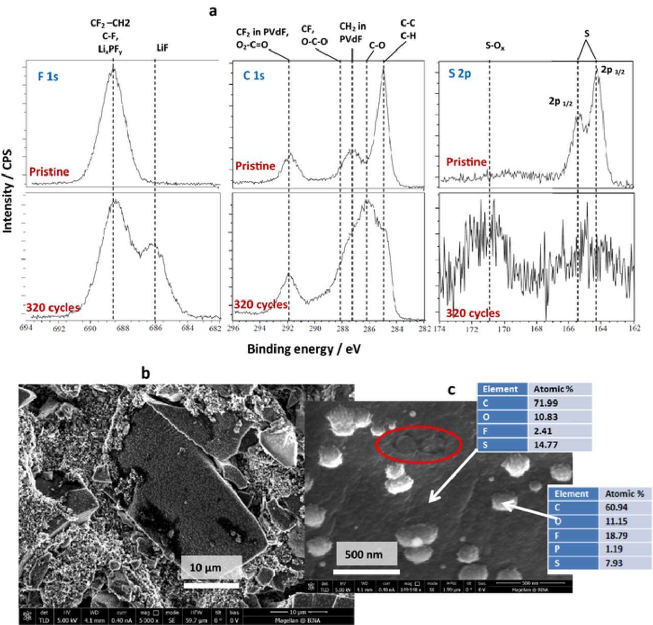
Figure 11. Surface characterization of S-PVDCDC electrodes cycled for 320 cycles in 1 MLiPF6/FEC/DMC electrolyte solution. (a) F 1s, C1s and S 2p XPS spectra and (b, c) SEM images and EDS results measured for pristine and cycled composite S-PVDCDC electrodes. (b) and (c) reproduced with permission from Ref. 40.
Surface films on the cycled S/PVDCDC electrodes are visible in SEM images (Figs. 11b and 11c). All PVDCDC particles are uniformly coated by surface films with attached bright spherical droplets of various sizes up to about 300 nm in diameter. This type of surface films morphology was described in Refs. 57,63 for the surface films which were formed on graphite composite electrodes in Li-ion batteries. The agglomerates thus observed were assigned to LiF crystals. This conclusion is in line with the results of EDS measured from the surface of the spherical agglomerates (Insets in Fig. 11c) and the XPS spectra of cycled electrodes. In these locations the content of fluorine is markedly higher than that on the dark areas in the images. The smooth part of the surfaces (dark area in the SEM images) is covered by surface films which are characterized by the presence of F and a relatively high content of oxygen. The sites marked in red in Figure 11c are obviously originated from the occasional removal of LiF crystals, probably due to mechanical reasons (upon washing the electrodes' samples for the ex-situ measurements). These traces provide an additional evidence for the existence of surface films on the smooth part of the S-C composite particles, which include polymeric matrices in which the LiF crystals are embedded.
Surface analysis performed for S/C electrodes cycled in the FSI-based IL electrolyte solution also confirms the formation of SEI on their surface.38 Fig. 12 shows XPS spectra collected from pristine S/AC1 electrode and the same electrode after being cycled in the IL based electrolyte solution. The F 1s spectra of cycled electrodes contain a signal of LiF at 685 eV (Fig. 12a).56 The N 1s spectra contain two peaks at 400.3 eV assigned to N− atoms in FSI anions64–67 and a peak at 398.9 eV, related to N−atoms in the products of FSI anion decomposition (Fig. 12b).65,66,68 The S 2p spectrum of the electrode shows peaks of two types of sulfur atoms in the surface films: a doublet at 168.2 eV and a non-resolved doublet at about 169.5 eV. These signals may relate to the products of the polymerization reaction of LiFSI and Li2S2 proposed by Kim et al.68 The two doublets, may be probably, assigned to sulfonyl amide groups in the resulted products, namely, F–S*(O2)–N–S(O2)– with sulfur atoms connected to one F and one N atom, and F–S(O2)–N–S*(O2)– with sulfur atoms bound to one S and one N atom (Fig. 12d).
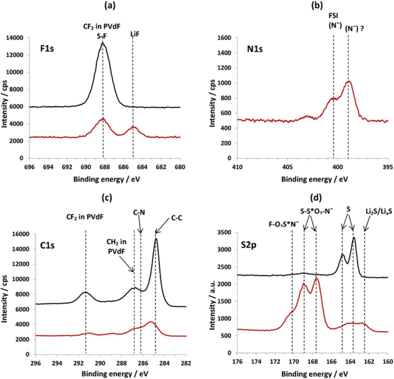
Figure 12. F 1s (a), N 1s (b), C1s (c) and S 2p(d) XPS spectra of pristine (black curves) and cycled in 0.5 M Li FSI in MPP FSI electrolyte solution at 30°C (red curves) composite S/AC1 electrodes. Reproduced with permission from Ref. 38.
Thus, the results of surface analysis of S/C composite electrodes cycled both in alkyl carbonates and IL based electrolyte solutions clearly demonstrate the presence of stable surface films on the electrodes surfaces. The electrochemical behavior of these systems as discussed above, clearly indicate that these surface films behave like SEI.
Conclusions
In this paper we attempted to review recent works devoted to the phenomenon of the S/C composite electrodes with sulfur confined in the micropores of the carbon matrices, reacting via quasi-solid state mechanism in Li-S cells. This reaction path is characterized by single charge and single discharge galvanostatic plateau, high irreversible initial discharge capacity and voltage hysteresis in the initial cycles. Based on the analysis of the literature and our intensive recent studies we demonstrated that the concept of small sulfur molecules confined in nano space cannot explain many of the experimental data related to QSS reaction mechanism of S/C cathodes in Li-S cells. The existence of sulfur in the form of small molecules in many cases is problematic considering the preparation procedures described in the works which demonstrated QSS behavior of S/C composite cathodes. Moreover, the confinement of sulfur in the form of small molecules in the micropores of carbon matrices is not a necessary condition for the realization of QSS mechanism. This conclusion may be confirmed by the ability of S/C cathodes based on carbons with pore size up to 2–3 nm to operate also according to QSS mechanism. Moreover, certain S/C composites cathodes exhibit both QSS and normal solid-liquid-solid (voltage profiles with two plateaus) mechanisms in different electrolyte solutions indicating that sulfur is encapsulated in the pores in its normal state (S8 molecules).36,38
We showed that a key role in the operation of S/C electrodes via a QSS mechanism plays SEI type surface films which are formed on the surface of the S/C composite electrodes during the initial discharge. The surface films thus formed prevent the encapsulated sulfur from a detrimental direct contact with liquid electrolyte solution and facilitates desolvation of Li ions, before they react with sulfur.
Acknowledgment
This work was supported by BASF and by the ISF, Israel Science Foundation in the framework of the INREP project.