Abstract
The addition of a compact titanium dioxide (TiO2) layer between the fluorine-doped tin oxide (FTO) coated glass substrate and the mesoporous TiO2 layer in the dye-sensitized solar cell (DSC) based on the iodide/triiodide redox couple (I−/I3−) is known to improve its current-voltage characteristics. The compact layer decreases the recombination of electrons extracted through the FTO layer with I3− around the maximum power point. Furthermore, the short-circuit photocurrent was improved, which previously has been attributed to the improved light transmittance and/or better contact between TiO2 and FTO. Here, we demonstrate that the compact TiO2 layer has another beneficial effect: it blocks the reaction between charge carriers in the FTO and photogenerated diiodide radical species (I2−•). Using photomodulated voltammetry, it is demonstrated that the cathodic photocurrent found at bare FTO electrodes is blocked by the addition of a compact TiO2 layer, while the anodic photocurrent due to reaction with I2−• is maintained.
Export citation and abstract BibTeX RIS

This is an open access article distributed under the terms of the Creative Commons Attribution 4.0 License (CC BY, http://creativecommons.org/licenses/by/4.0/), which permits unrestricted reuse of the work in any medium, provided the original work is properly cited.
Dye-sensitized solar cells (DSCs) have been intensively investigated in last decades since Grätzel and co-workers made a breakthrough by employing a mesoporous structure for the semiconductor layer.1,2 During more than 30 years, intensive research and development has been carried out to improve the efficiency of DSCs and to enhance their environment-friendly natures; new materials have been proposed for the solar cell components, dyes,3,4 electrolyte5,6 and counter electrode,7 and preparation methods and processes on different substrate such as plastic,8 textile9 laminated metal, and other have been elaborated.10 So far, the highest sunlight to electricity conversion efficiency reported for this type of device is 14%.11 To further improve the efficiency of DSCs, it is important to minimize the recombination loss before the injected electrons reach the external circuit. After the electron has been injected into the conduction band of TiO2, electrons in TiO2 can recombine with oxidized species in the redox electrolyte or oxidized dye molecules. Additionally, electrons that reach the fluorine-doped tin oxide (FTO)-coated glass substrate may still undergo interfacial reaction with oxidized species in the electrolyte.
Frequently, a thin compact metal oxide layer is deposited on the FTO substrate in dye-sensitized solar cells before deposition of the mesoporous TiO2 film.12
The function of this thin layer is to limit the reaction between the oxidized species in the electrolyte and electrons in the FTO.13,14 The compact layer can have a large effect on solar cell performance, especially when organic dyes are employed as sensitizer.15 In the case of iodide/triiodide (I−/I3−) based electrolytes, it has been shown that the reduction of I3− at the FTO substrate is significantly suppressed when a thin compact TiO2 layer is added.13 Reduction of triiodide to iodide is a recombination pathway for the injected electrons in the DSCs, and this reaction can give significant current losses at the maximum power point of the DSC. When the compact layer is deposited on FTO, this recombination is diminished and, as a result the fill factor is improved. When the potential is close to the open-circuit voltage (Uoc) of the solar cell (or, equivalently, the photoelectrode potential is close to the conduction band of TiO2) reduction of I3− mainly occurs via the mesoporous TiO2. Under such conditions, the back reaction via FTO is less pronounced since the surface area of TiO2 is orders of magnitude larger (ca. 1000 times) compared to that of FTO. When the light intensity is very low, however, the back-reaction via FTO can still be prominent under open-circuit conditions because of the low electron concentration in the mesoporous TiO2.16–18 In the case of the other redox couples such as ferrocene/ferrocenium,19,20 cobalt II/III complexes5,21–23 and copper I /II complexes,6,24–26 the compact layer preventing recombination via the FTO substrate is crucial to realize functional DSCs. The compact layer is also an essential layer to prevent the recombination in perovskite solar cells.27
Different methods for deposition of the compact TiO2 layer have been investigated, such as spray pyrolysis,28 chemical bath deposi-tion,29–31 electrochemical deposition,32,33 layer-by-layer deposition,34 atomic layer deposition(ALD),35,36 sol-gel,37 and sputtering.19,38–40 Moreover, compact layers have been prepared by using Nb-doped TiO241 and other materials such as ZnO42–44 and Nb2O5.45–48
Under short circuit conditions, the potential at the FTO electrode is identical to the redox potential of the electrolyte provided that a sufficiently electrocatalytic counter electrode is used. Although an electrochemical reduction reaction is possible at the FTO substrate as well, the recombination via the FTO substrate will be negligible due to the poor electrocatalytic properties of this substrate. Interestingly, an improvement of the photocurrent in the presence of the compact layer has been observed in previous studies.15,16,19,28,31,39,41,46,47,52,53 One of the explanations for this is an enhanced transmittance due to the presence of the underlayer.23,40,54 Another explanation is a better electrical and physical contact between FTO and TiO2 resulting in a decreased resistance at the interface between the two materials.41,52,55 We think that this explanation is valid. In addtion to these reasons, we found one more explanation for the increase of the photocurrent in presence of the compact layer.
In DSCs, the regeneration of the oxidized dye is one of the essential processes to realize high efficiency solar cells. For a highly efficient regeneration with I−/I3− redox electrolyte, a difference of ca. 0.75 V is necessary between the redox potential of I−/I3− and the HOMO of the dye.56 Moreover, the concentration ratio of anion and cation in the redox electrolyte affects the regeneration process since the redox potential shifts following to the Nernst equation.57 The reason for this relatively large required driving force is that the oxidation from I− to I3− is a two-electron redox reaction via an intermediate step in which the diiodide radical anion (I2−•) is formed. It was reported that the redox potential of I2−• is more positive than the one for I−/I3− in acetonitrile.58 Moreover, I2−• can be produced in several reaction processes.59–61 The recombination between the electron in TiO2 and I3− is a loss process in DSCs; contrarily, I2−• is not reactive with electrons in TiO2.62
In this study, DSC devices were fabricated with and without TiO2 compact layer. The effect of compact layer on both fill factor and short-circuit photocurrent have been investigated. Photomodulated voltammetry measurements showed that the compact layer blocks the reaction between FTO and the reactive intermediate I2−•. This is an additional explanation for the enhancement of the photocurrent in the presence of the compact layer.
Experimental
Compact TiO2 layers on FTO (TEC8, Pilkington) were prepared by spray pyrolysis as described in the literature.28 For this a solution of 3.6 ml acetylacetone and 2.4 ml Ti-isopropoxide diluted with 54 ml of ethanol was sprayed onto the FTO substrate on a hot plate (450°C). One spray cycle builds approximately 10 nm-thick TiO2 layer.
Mesoporous TiO2 films were prepared by the doctor-blade technique on FTO or compact TiO2/FTO substrates. The area and thickness of the mesoporous TiO2 films were 0.32 cm2 and ca. 6 μm, respectively. The film thickness was measured using a Veeco Dektak 150 profilometer. No TiCl4 post-treatment was applied to the samples. TiO2 films were sintered in the furnace at 450°C for 30 min. When the films were cooled down to 80°C, they were immersed into a 0.5 mM dye solution of N719 (di-tetrabutylammonium cis-bis(isothiocyanato)bis(2,2'-bipyridyl-4,4'-dicarboxylato)ruthenium(II) (Solaronix S.A) in a mixture of acetonitrile and tert-butanol (1:1 in volume) for 17 h. The sensitized films were rinsed in acetonitrile solution. Sandwich cells were assembled using platinized FTO (TEC8, Pilkington) as a counter electrode and 50 μm thick Surlyn thermoplastic (DuPont) as spacer. After injection of the electrolyte, the cells were sealed by using a Surlyn polymer film and a microscope cover slip. The electrolyte composition was 0.6 M TBAI (tetrabutylammonium iodide), 0.1 M LiI, 0.05 M I2, 0.5 M 4TBP (4-tert-butylpyridine) in acetonitrile. All chemicals were purchased from Aldrich, unless noted otherwise and used without further purification.
Scanning electron microscope (SEM) images were recorded on a Zeiss Leo 1550 scanning electron microscope. Transmission spectra of the substrates were measured with a fiber optics spectrophotometer with integrating sphere (HR-2000 Ocean Optics). Tafel plots were obtained from current-voltage measurements on an Autolab PGstat12 potentiostat.
Current-voltage (I-U) measurements on solar cell devices were carried out at 1000 W/m2 simulated Air Mass 1.5 G illumination, equivalent to 1 sun. The electron lifetime was estimated by obtaining the decay time constants upon square-wave voltage modulation. For this, the solar cell was illuminated at the open-circuit condition with a red LED (Luxeon Star 1 W, λmax = 640 nm). Then, the light intensity perturbed with < 5% with respect to the steady-state light intensity for a constant period. The voltage responses were fitted using first-order decay kinetics, and time constants were obtained accordingly. The light intensity of the steady-state illumination was changed by regulating the applied voltage to the LED. Electron lifetime constants at each light intensity were measured and plotted vs. the open-circuit photovoltage. (Additional explanations for the electron lifetime are provided in Supporting Information S1.) The photomodulated voltammetry (PMV) setup consisted of a blue LED light source (1 W Luxeon Star with optic, royal blue max 460 nm), a two-electrode electrochemical cell, a potentiostat (EG&G PAR273A) and a lock-in amplifier (Stanford Research SR830). The TTL output from the internal reference of the lock-in amplifier is used to control the output of the LED driver (Luxdrive Buckpuck 3021) resulting in on/off modulation of the LED. The frequency range used was 10 kHz to 1 Hz. A voltage signal proportional to the measured current was connected from the potentiostat to the lock-in amplifier. The PMV response was recorded using steps of 20 mV (time per step 5 s). No corrections for the internal voltage drop in the 2-electrode system were made. Potentials are reported versus the redox potential of the solutions. The same electrolyte used for the DSC samples was used for this measurement.
Results and Discussion
In Figure 1, the surface morphology of the samples used in this study has been studied by scanning electrode microscopy (SEM). The FTO layer consists of SnO2 crystals larger than 100 nm (Fig. 1a). The spray pyrolysis method leads to a homogeneous layer of TiO2 covering the surface of the FTO (Fig. 1b). Spray pyrolysis creates a blocking layer with dense appearance. However, the shape of FTO surface can be still traced. More details will be discussed later, including electrochemical analysis.
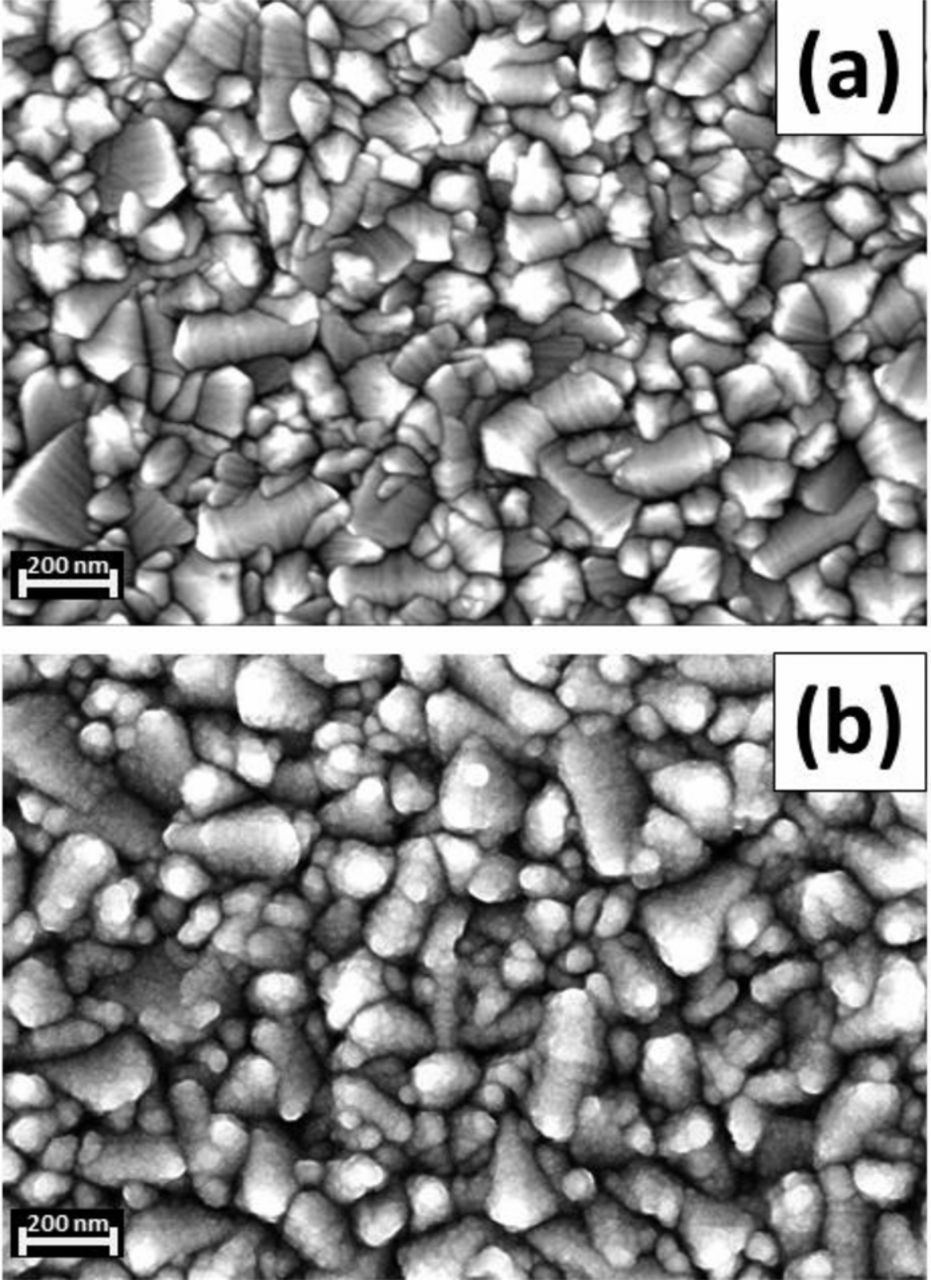
Figure 1. SEM pictures of (a) FTO substrate and (b) TiO2 compact layer (∼50 nm) prepared by spray pyrolysis on FTO.
Linear scan voltammetry was carried out on sandwich cells using the compact TiO2 layer covered FTO electrode as the working electrode and a platinized FTO electrode as the counter electrode. The Tafel (logarithm of current vs. voltage) plot representation of j-V measurements on these cells is shown in Figure 2. The compact layers on FTO show a decrease in the reduction current of I3− (at negative potentials) and in the oxidation current of I− (at positive potential) compared to the bare FTO electrode. It should be noted that the bare FTO electrode was not heat treated (heat-treatment will lead to an increase in faradaic currents). The TiO2 thickness of the blocking layers, determined by profilometry, was ∼50 nm for the spray-pyrolysis method; the thickness can be tuned by changing the amount of spray during the deposition. From the result of the Tafel plot, the thickness of 50 nm is sufficient to have a good blocking effect. The blocking effect of the 100 nm thick TiO2 compact layer is almost identical. The decrease of both oxidation and reduction current by having the compact layer indicates the formation of a pinhole-free layer. This is consistent with the SEM observations. The blocking effect to the reaction via the FTO substrate is significant for the potentials values at around the maximum power point of DSCs (at potentials negative of about −0.5 V).
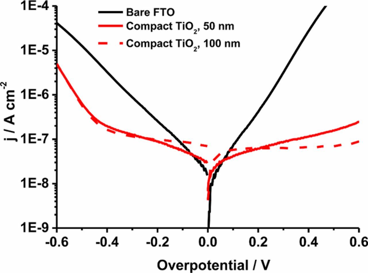
Figure 2. Tafel plots of a FTO/electrolyte/Pt-CE cell (black) and FTO/compact TiO2/electrolyte/Pt-CE cells; compact layer prepared by spray pyrolysis, 50nm (red) and by spray pyrolysis, 100nm (red dash).
Current-voltage characteristics under light and dark have been measured for the cells with and without compact layer (Figure 3). All parameters (short-circuit photocurrent density Jsc, open-circuit photovoltage Uoc, and fill factor) are improved by the presence of a TiO2 compact layer. Especially the improvement of the Jsc and fill factor is pronounced. However, for thicker TiO2 blocking layers of ca. 200 nm, the Jsc of the cell is reduced compared to the cell without compact layer. This is most likely due to the reduced transmittance of the compact layer/FTO substrate compared to bare FTO, as will be shown later. (A statistical data is shown in Supporting information S2.) The Uoc is also increased by ca. 10 mV in the presence of the compact layer. At the open circuit condition (high cathodic overpotential), the blocking effect of the compact layer becomes less important, because the recombination reaction is then dominated by reduction of triiodide via the mesoporous TiO2 film.
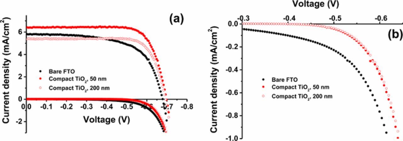
Figure 3. (a) IV characteristics in darkness and under 1 sun illumination of DSCs without compact layer (black), and with compact layer: spray, 50 nm (red, filled circle) and spray, 200 nm (red, open circle). (b) Enlargement of the dark current shows in (a).
In Figure 3b, the I-U measurements in dark are shown. It is clear here that the dark current is blocked by the presence of the compact layer. This dark current is due to the reduction of I3− at both TiO2 and FTO. This blocking effect is contributing to the improved fill factor (ff) of the solar cell. However, this blocking effect observed in dark I-U measurement is relatively small when it is compared to the improvement of fill factor. It implies that there are other contributions to improve the fill factor under illumination by the presence of the compact layer.
In Table I, the characteristic parameters of the different solar cells are shown. The photocurrent increased by ca. 10% by the presence of the blocking layer, while the fill factor improved by ca. 20%. The open-circuit photovoltage was only slightly increased (ca. 2%). In total, the conversion efficiency improved by ca. 35%. The improvement of the fill factor by introducing the compact layer is expected since the reduction current of I3− at the FTO substrate is decreased. The very small increase of the UOC points to the fact that at this potential, about 100 mV more negative than the potential at the maximum power point, most of the electrons recombine through the mesoporous TiO2. Interestingly, Jsc was significantly higher in the presence of the compact layer. It should be noted that this increase of the photocurrent is observed in spite of a slightly decreased transmittance of the substrate by the presence of the compact layer, as will be discussed later.
Table I. Solar cell characteristics of dye-sensitized solar cells with and without compact TiO2 underlayer.
| Jsc [mA cm−2] | Uoc [V] | Fill factor | Efficiency [%] | |
|---|---|---|---|---|
| No underlayer | 5.79 | 0.68 | 0.634 | 2.49 |
| Spray, 50 nm | 6.36 | 0.70 | 0.759 | 3.38 |
| Spray, 200 nm | 5.34 | 0.69 | 0.773 | 2.85 |
In Figure 4, the electron lifetime is shown as a function of applied potential. When the compact layer is absent, the slope of the lifetime versus Uoc is clearly different at potentials positive of ca. −0.55 V. On the other hand, the slope of the lifetimes of the cell with compact layers does not change. In the presence of the compact layer the back-reaction of the injected electrons occurs only via TiO2. When the compact layer is absent, there is an additional back-reaction via FTO. When the voltage is positive of −0.55 V, the back-reaction via TiO2 is much slower than via FTO. Therefore, the back reaction mostly occurs via FTO in lower overpotential region. When the potential is negative of −0.55 V, the back reaction via mesoporous TiO2 becomes dominant. This result shows that the presence of a compact underlayer is preferable when electron recombination processes in DSC are studied. It has been reported previously by Cameron et al.14
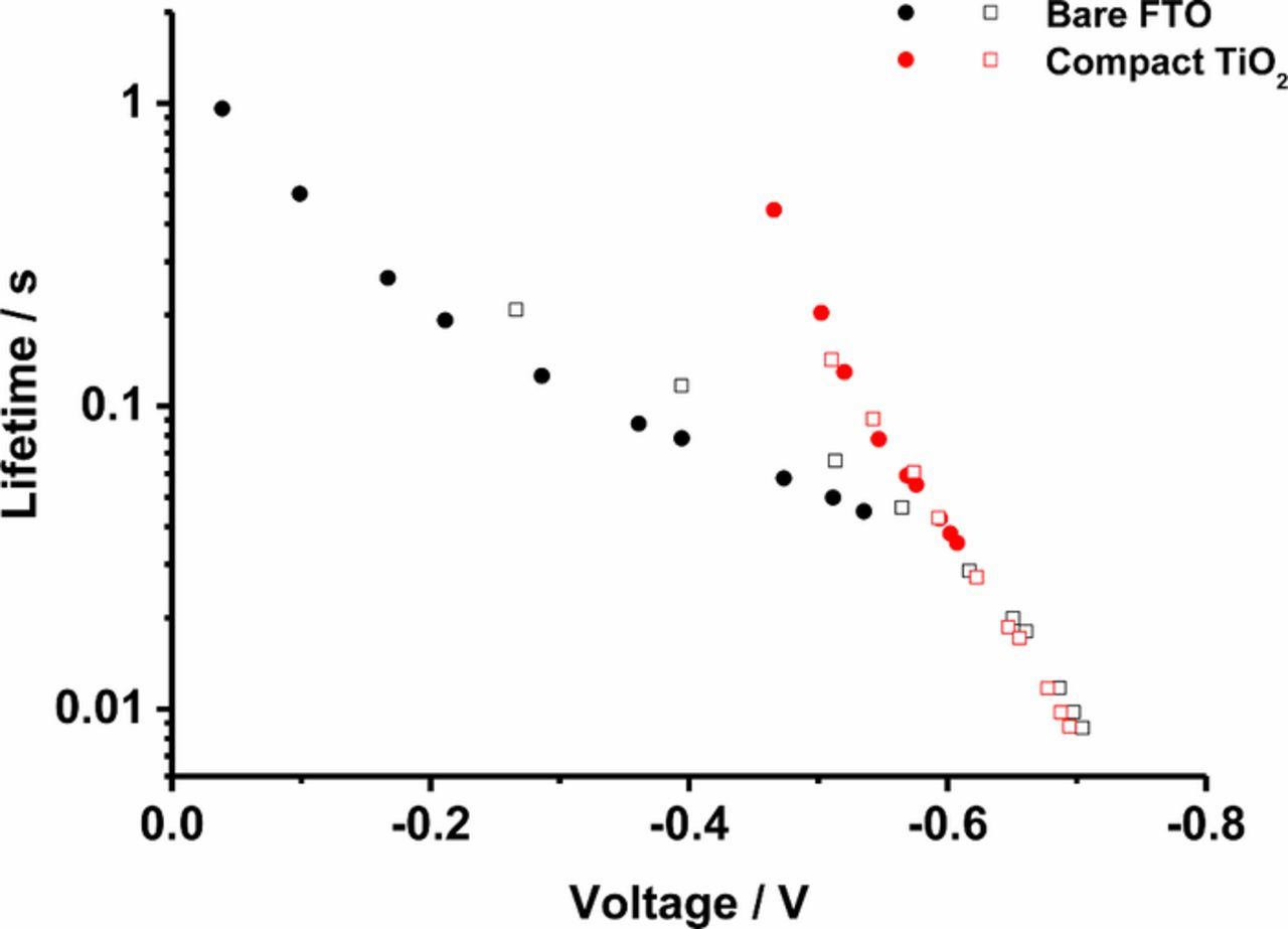
Figure 4. Electron lifetime as a function of Uoc in DSC devices without compact layer (black) and with compact layer prepared by spray pyrolysis (red). Note: results of two identical samples are shown for no compact layer (black) and spray pyrolysis (red).
We will now discuss the enhancement of Jsc by the presence of the compact TiO2 layer. In former studies, explanations were i) improvement of the transparency of FTO by the presence of the compact layer,30,54 ii) a better physical and electrical contact between the substrate and the mesoporous TiO241,55,63 and iii) an higher electron concentration in the conduction band of TiO2 due to the blocking effect of the underlayer.15,41,46,53 The short-circuit current density is directly related to the incident photon to current conversion efficiency (IPCE) under short-circuit conditions. IPCE can be expressed by the following formula:
![Equation ([1])](https://content.cld.iop.org/journals/1945-7111/166/9/B3203/revision1/d0001.gif)
where LHE is the light harvesting efficiency and ϕinj is the quantum yield for electron injection, respectively, and ηcc the charge collection efficiency. A change of the photocurrent is caused by a change in these parameters. It is reasonable to assume that ϕinj does not change by the presence of the compact layer. Therefore, the enhancement of the photocurrent is caused an increase of the LHE and/or the collection efficiency.
In Figure 5, transmission spectra of the bare FTO substrate and FTO substrates with spray-pyrolysis compact layers of different thickness are shown. The transmission spectra were measured using an integrating sphere and include therefore forward-scattered light. The FTO substrate without compact layer has the highest transparency in the visible light region. The total transmittance of the substrate is decreased by the presence of the compact TiO2 layer, because of its higher refractive index compared to FTO, resulting to additional reflection. Comparing the transmission spectra of FTO and the FTO with a 50 nm thick compact layer, the transmittance decreased by ca. 4% in the visible light region (400-800 nm). This leads to a small decrease of the LHE in DSCs with compact underlayers. It is noted that the situation is slightly different in the actual solar cell, where the FTO/compact layer is in contact with liquid electrolyte rather than air, so that reflection losses will be lessened. Although the LHE decreases by < 4% for 50 nm thick compact layer, Jsc in actual DSCs was found to increase by ca. 10% by introduction of the compact TiO2 layer. The adsorption of N719 dye on the compact layer will increase Jsc, but this effect will be negligible due to the much larger amount of the dye on the surface of the mesoporous film. Furthermore, N719 dye can adsorb to the surface of FTO as well.64
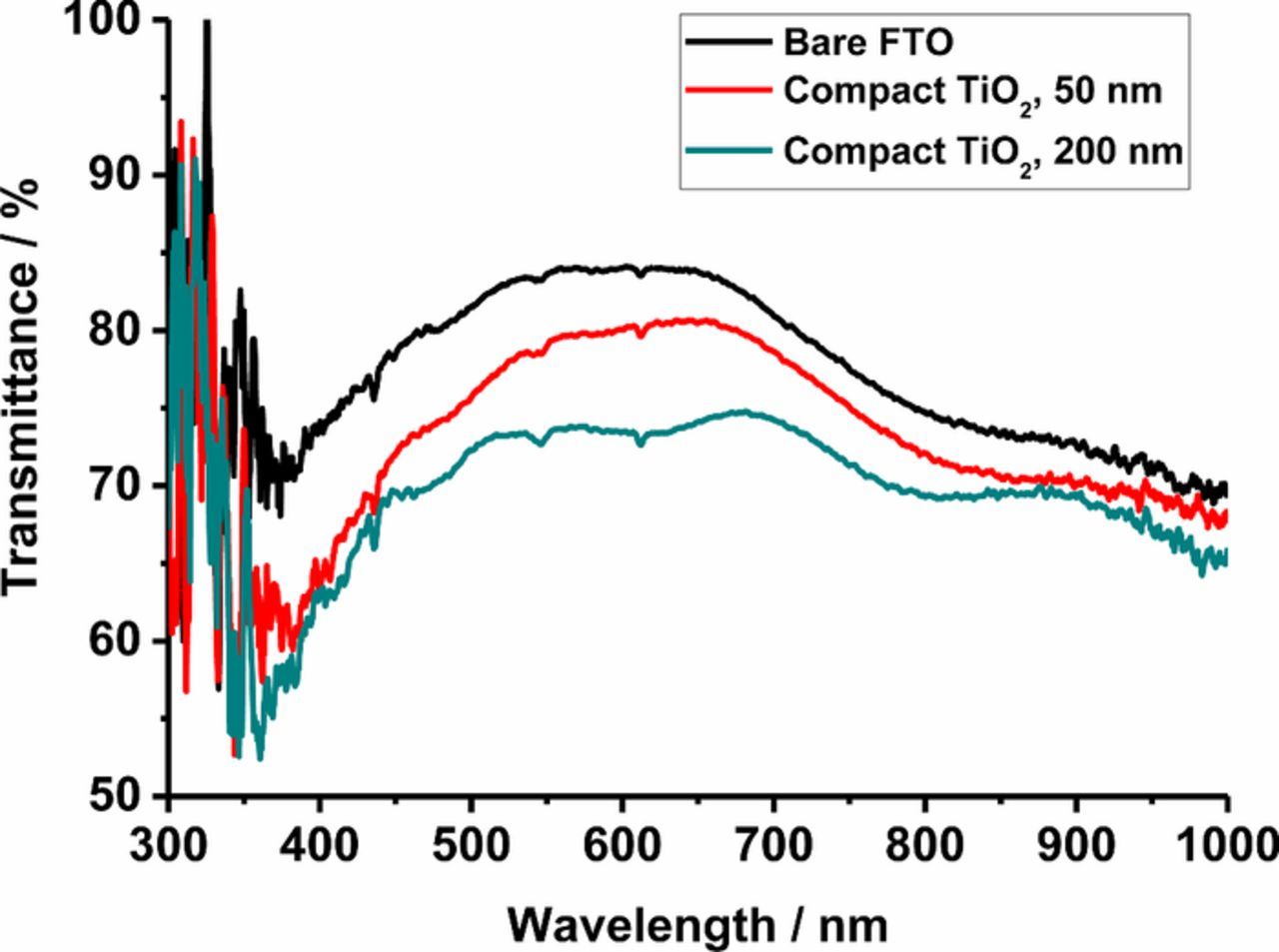
Figure 5. Transmission spectra of FTO and FTO with compact TiO2 layer prepared by spray pyrolysis. Bare FTO (black), 50 nm thick underlayer (red) and 200 nm (green).
The charge collection efficiency under short-circuit conditions is not expected to change due to the presence of a compact layer. The recombination current via FTO should be negligible since its potential is close to the redox potential of the electrolyte. Improved adherence of the mesoporous TiO2 may lead to a higher charge collection efficiency, but in this study no adherence problems were observed. This implies that a reconsideration for the charge collection efficiency under the short-circuit condition is necessary to understand the enhancement of the photocurrent.
We propose here a different effect of the compact TiO2 layer in DSC: the increased photocurrent could be a result of blocking the electron transfer from FTO to reactive intermediates that are formed in the iodide/triiodide electrolyte. The diiodide radical (I2−•) is formed in the regeneration process of the oxidized dye.56 The reaction sequence is the following:
![Equation ([2])](https://content.cld.iop.org/journals/1945-7111/166/9/B3203/revision1/d0002.gif)
![Equation ([3])](https://content.cld.iop.org/journals/1945-7111/166/9/B3203/revision1/d0003.gif)
![Equation ([4])](https://content.cld.iop.org/journals/1945-7111/166/9/B3203/revision1/d0004.gif)
![Equation ([5])](https://content.cld.iop.org/journals/1945-7111/166/9/B3203/revision1/d0005.gif)
I2−• is formed when (D–I) reacts with iodide (Reaction 4). Then, two I2−• react to form triiodide and iodide (Reaction 5). I2−• can also be formed when I3− absorbs light:65
![Equation ([6])](https://content.cld.iop.org/journals/1945-7111/166/9/B3203/revision1/d0006.gif)
![Equation ([7])](https://content.cld.iop.org/journals/1945-7111/166/9/B3203/revision1/d0007.gif)
The generated diiodide radical is a stronger electron acceptor than triiodide and it can react with the electrons in FTO (Reaction 8) since the redox potential of I2−•/I− is more positive than that of I3−/I−.56,66 Therefore, the reduction of I2−• will take place even at short-circuit conditions. In case of mesoporous p-type NiO electrodes, Reaction 8 has been found to give a cathodic photocurrent:67
![Equation ([8])](https://content.cld.iop.org/journals/1945-7111/166/9/B3203/revision1/d0008.gif)
On the other hand, I2−• is a stronger electron donor than iodide. It can therefore donate an electron to the FTO resulting to the formation of I3− (Reaction 9):
![Equation ([9])](https://content.cld.iop.org/journals/1945-7111/166/9/B3203/revision1/d0009.gif)
The photoinduced formation of I2−• can therefore induce both anodic and cathodic photocurrents at the FTO electrode, see Figure 6. The addition of a compact layer will significantly affect these reactions at the substrate, and is, as will be shown below, one of the reasons for the improvement of the short-circuit photocurrent in DSCs with a compact TiO2 layer. From the energetic diagram, the electrons in the conduction band of TiO2 can recombine with I2−•. However, no evidence of reaction between electrons in TiO2 and I2−• was found in a spectroscopic study.62
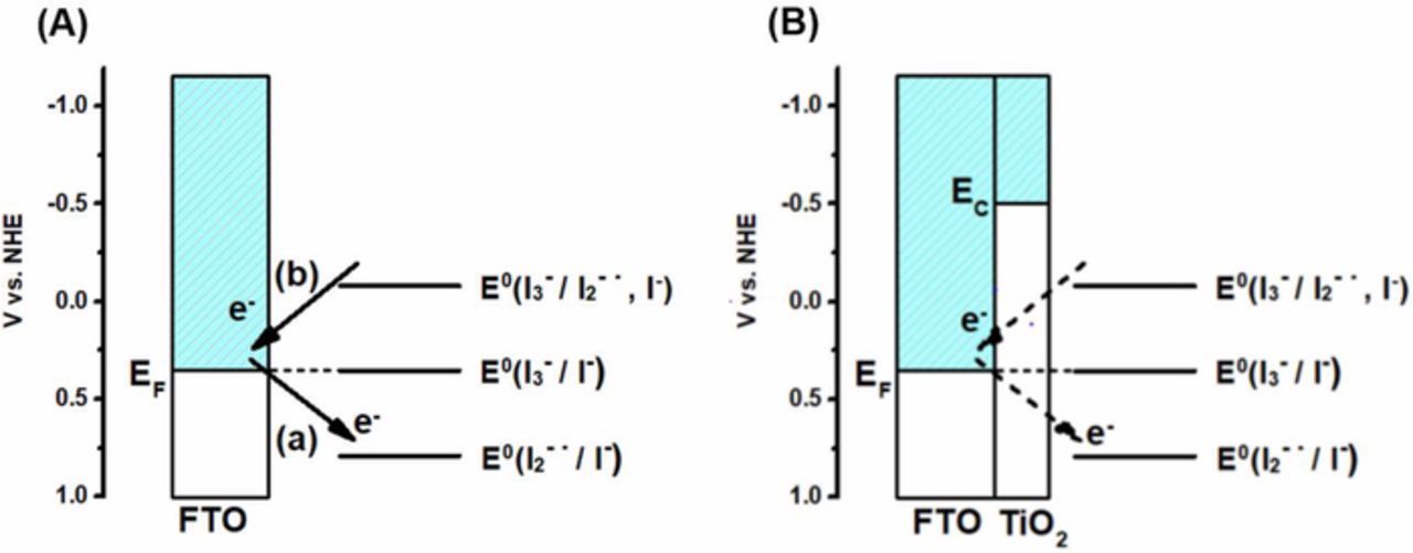
Figure 6. Schematic energy level diagram of an FTO electrode (A) without and (B) with compact TiO2 layer in contact with iodide/triiodide electrolyte under short-circuit conditions. Reactions (a) and (b) refer to reduction and oxidation of I2−•, respectively.
Photomodulated voltammetry was carried out for the sandwich type cells using platinized FTO as the counter electrode and FTO or FTO with compact TiO2 layer as the working electrode (Figure 7). In addition, cells with a mesoporous TiO2 film (without sensitizer on the surface) were studied. On the bare FTO electrode, the photogenerated I2−• yielded a cathodic modulated photocurrent at negative applied potentials, close to zero current without bias potential and a very small anodic photocurrent at positive potentials. This indicates that rates for Reactions 8 and 9 are similar for zero and positive potentials, while the application of a negative potential promotes Reaction 8, which gives a cathodic photocurrent. Upon application of a compact TiO2 layer on the FTO substrate, modulated photocurrent is anodic in nearly the whole measured potential range, showing that the compact layer effectively blocks the reduction Reaction 8, while oxidation Reaction 9 still can take place (see Figure 6).
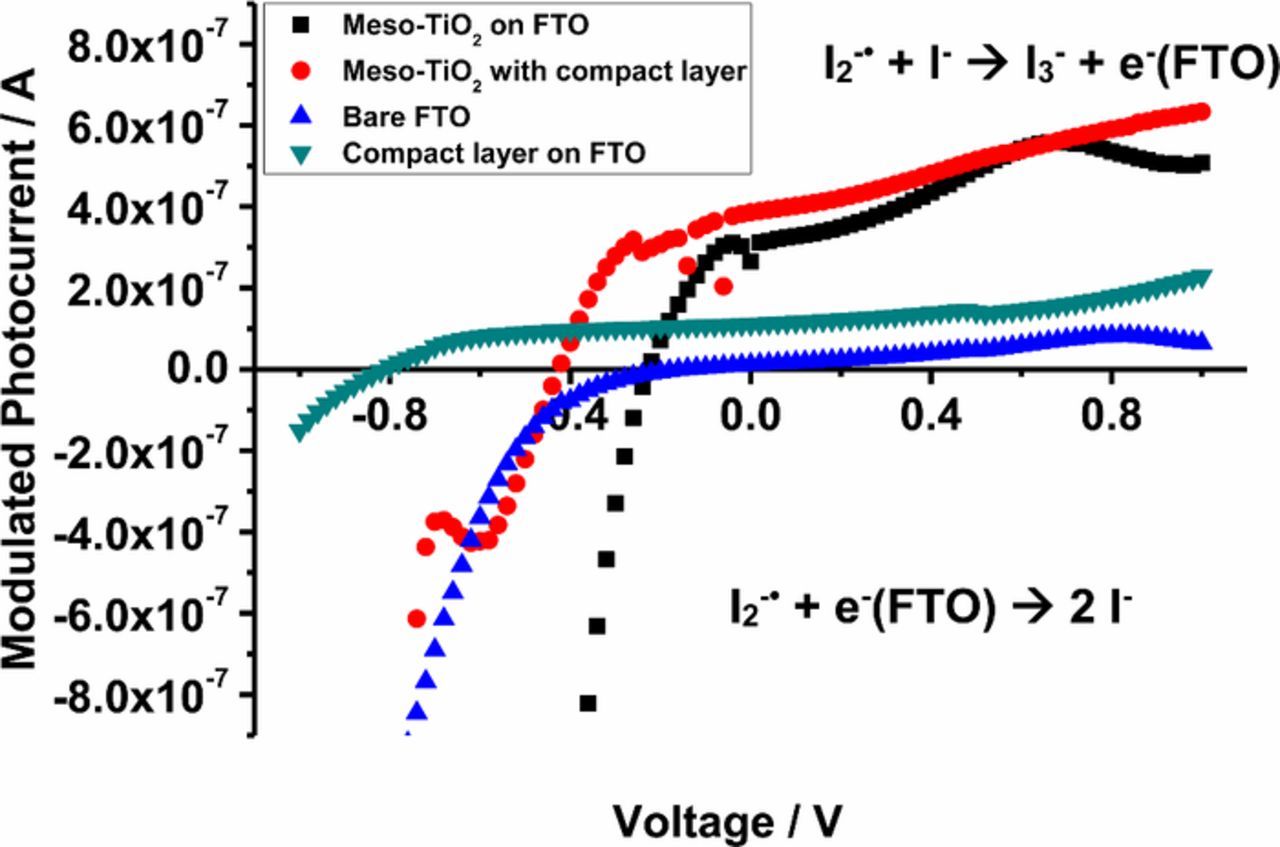
Figure 7. Photomodulated voltammetry of FTO and TiO2 with/without compact layer. Bare FTO (blue), FTO with underlayer (green), mesoporous TiO2 on FTO (black), and mesoporous TiO2 on underlayer (red).
Upon addition of a mesoporous TiO2 film on these substrates, the anodic photocurrent is increased. This is attributed to several factors. First, less of the FTO surface (that can give cathodic photocurrents) is in direct contact with the electrolyte. Secondly, the mesoporous structure ensures that I2−• has a much larger chance to encounter the electrode surface during its short lifetime. Finally, as the electron concentration is low in the TiO2, Reaction 8 does not occur unless a negative potential is applied. Meyer et al. could not find evidence for reduction of I2−• at TiO2 in their experiments,62 suggesting that Reaction 8 does not occur on TiO2, or is kinetically inhibited. The transition from anodic to cathodic modulated photocurrent occurs at an about 200 mV more negative potential when an underlayer is present at the mesoporous electrodes.
The observed modulated photocurrents are very small (in the order of 200 nA cm−2), and it is reasonable to question whether photogenerated I2−• actually can account for significant photocurrent effects in actual DSC devices. The amount of I2−• generated in our PMV experiment was in the order of 6 μM, as was determined using photoinduced absorption measurements under similar conditions. Calculations show that the I2−• concentration under operating conditions is in the order of 3 μM.56 A simple calculation shows that indeed a significant photocurrent in the order of 10−4 A cm−2 may be expected under one sun illumination. The resulting effect in real DSCs is that the blocking TiO2 underlayer improves the solar cell by blocking the cathodic photocurrent due to reduction of photogenerated I2−• at the FTO/electrolyte contact. It is further noted that the photogenerated I2−• can inject electrons into the compact and mesoporous TiO2 films, thereby generating an anodic photocurrent. It is not certain if this contribution to the photocurrent from photogenerated I2−• will occur and benefit the photo-current in actual DSC devices, because the dye layer may block I2−• from accessing the TiO2 surface.
Conclusions
The use of a compact TiO2 layer on the FTO substrate underneath the mesoporous TiO2 film is beneficial in dye-sensitized solar cells with iodide/triiodide electrolytes for several reasons: (1) it decreases the rate of reaction between electrons in FTO and I3−, leading to a better fill factor in the solar cell. (2) it blocks the reaction between electrons in FTO and photogenerated I2−•, leading to an increase in short-circuit current density. The latter effect was observed using photomodulated voltammetry.
Acknowledgments
The Swedish Energy Agency, the Swedish Research Council (VR) and the Knut and Alice Wallenberg Foundation are acknowledged for financial support. E. U. acknowledges funding from the Swedish Research Council (Project 2015-00163) and Marie Sklodowska Curie Actions, co-fund Project INCA 600398.
ORCID
Kazuteru Nonomura 0000-0002-5329-9259
Nick Vlachopoulos 0000-0001-5192-8122
Eva Unger 0000-0002-3343-867X
Anders Hagfeldt 0000-0001-6725-8856
Gerrit Boschloo 0000-0002-8249-1469