
Abstract
We have investigated the inkjet-printing of TiO2 films for the fabrication of dye-sensitized solar cells (DSSCs). In order to realize the uniform printing of TiO2 films, the co-solvent ink was designed by introducing a drying agent to the ink. This co-solvent ink induces a circulating flow within ink droplets and leads to the uniform lines and films by inkjet. A theoretical model was used to predict the optimal ink-droplet pitches for the inkjet-printing of uniform lines. This model also contributes to the formation of uniform films since they are filled with the inkjet-printed lines. The inkjet-printed TiO2 films were used as photoelectrodes for dye-sensitized solar cells. The thickness of the inkjet-printed TiO2 films was varied to optimize the photovoltaic performance of DSSCs. Since no organic additives were introduced into the TiO2 inks, the feasibility of reducing the annealing temperature for TiO2 photoelectrodes was investigated. This study may suggest an opportunity to fabricate DSSCs at low temperature.
Export citation and abstract BibTeX RIS
Inkjet printing of functional materials has been attracting significant attention in the light of recent attempts to manufacture various electronics such as light-emitting diodes, thin film transistors, solar cells, memory devices, sensors, biological devices, passive circuit elements, etc.1–5 This versatility of the inkjet printing technology is attributed to its ability to directly deposit various materials on the desired locations with high material usage. Inkjet printing also provides an opportunity to mitigate the cost-reduction pressure in electronics industries by not only reducing the processes steps but also offering an easy scalability to large area electronics.1,6
Since the inkjet printing utilized a liquid form of materials, or inks, consisting of nanoparticles dispersed in various solvents, it is critical to understand the evaporation nature of ink droplets ejected from the inkjet nozzle. It is commonly observed that a ring-like accumulation ("coffee-ring" pattern) of nanoparticles develops as the solvent evaporates from the ink droplets.7 Such an irregular deposit of nanoparticles imposes critical restrictions on the application of inkjet printing to various electronics which require fine-patterns and uniform film coatings. The study on "coffee-ring" phenomenon by Deegan et al. indicated that a predominant solvent loss by evaporation from the contact line of the ink droplet was counterbalanced by an outward flow of solvent from the interior of the ink droplet since the contact line was pinned. This outward flow moves all the nanoparticles towards the contact line of the ink droplet.7 Several reports indicated that "coffee-ring" phenomenon could be obviated by incorporating a drying agent into the main ink solvent.8,9 The drying agent with a higher boiling point and lower surface tension compared to the main ink solvent induces a circulating flow within the ink droplet as the ink evaporates, leading to a uniform placement of nanoparticles over the entire contact area of the ink droplet.
Line patterns or film coatings by inkjet result from a coalescence of ejected ink droplets or multi-path printing of the printed lines. So, the pitches among the ink droplets as well as the inkjet-printed lines play important roles in producing uniform line patterns and film coatings. With a theoretical model by considering a spreading of the ink droplets on a substrate, the optimum values of both droplet-to-droplet and line-to-line pitches were investigated for the uniform lines patterns and film coatings, respectively. This study contributed to predicting a process window for the inkjet-printing of uniform TiO2 lines and films. These inkjet-printed TiO2 films were applied to the fabrication of dye-sensitized solar cells (DSSCs).
The inks used in the inkjet printing have a relatively low viscosity (less than 20 cPs).10 It indicates that the amount of organic additives used in the inks is none or very minimal compared to the high viscosity (1,000 ∼ 10,000 cPs) paste for the screen printing which is widely used in the conventional DSSC fabrication.11 This conventional DSSC fabrication usually requires an annealing temperature as high as 450 ∼ 500°C in order to remove a large amount of binders from the high viscosity TiO2 paste. From this aspect, the inkjet printing of TiO2 electrode may give rise to a possibility to reduce the annealing temperature. Even though it is well understood that there is another important implication of the high temperature annealing to TiO2 photoelectrodes such as the improvement of the connectivity among TiO2 nanoparticles and their adhesion to the transparent conducting electrodes, it is worth evaluating how much the annealing temperature of TiO2 photoelectrodes for DSSCs can be reduced with the inkjet printing.
Experimental
TiO2 nanoparticles from Degussa (P25, 80% anatase & 20% rutile) were used in TiO2 ink formulation. Both single- and co-solvent TiO2 inks were formulated by dispersing the TiO2 nanoparticles in water (boiling point: 100°C, surface tension: 72.8 dyn/cm) and a mixture of 80 vol% water as a main solvent and 20 vol% drying control agent, respectively. N,N-dimethylformamide (DMF; boiling point: 153°C, surface tension: 40.4 dyn/cm) was decided as a drying agent based on the comparison of its boiling point and surface tension with those of water. TiO2 solid content in both single- and co-solvent inks was maintained at 2 vol% in the entire experiment. The formulated inks were printed by Omni-200 inkjet unit (Unijet) which has a piezoelectric nozzle with 50 μm orifice from Microfab technology. The ejected ink volume was maintained at 165 pl during the entire inkjet printing with the ink ejection speed of 2.5 ∼ 3.0 m/s. The shapes of the inkjet-printed droplets and lines were monitored by Veeco Dektak 150 surface profiler and CCD camera equipped in the inkjet-printing unit.
The formulated TiO2 inks were printed by inkjet on fluorine-doped tin oxide (FTO) coated glasses (TEC8, Pilkington, 8 Ω/sq, Transmittance of 80% at 550 nm, glass thickness of 2.3 mm). The FTO glasses were heated on the heating block at 60°C during the entire printing process. The inkjet-printed dimension of TiO2 films was 5×5 mm2 on FTO coated glasses (15×20 mm2). The thickness of the inkjet-printed TiO2 films was intentionally varied in the range from 5 μm to 20 μm by repeating a single layer printing of TiO2 several times. A single inkjet-printing of TiO2 film at our optimal ink-droplet and line-to-line pitches corresponded to 5 μm thick film. The inkjet-printed TiO2 films were annealed by a box furnace at temperatures ranging from 150°C to 450°C for 30 min. The annealed TiO2 photoelectrodes were immersed in absolute ethanol containing 0.5 mM of ruthenium-complex (N-719 dye, Solaronix) for 24 h at 25°C. The surface morphology and porosity of the inkjet-printed TiO2 films were analyzed by a field emission scanning electron microscope with focused-ion-beam (FE-SEM with FIB; Helious 2000E). Pt counter electrodes on FTO glasses were prepared from H2PtCl6 2-propanol solution at 400°C for 20 min. Thermal adhesive film (Surlyn, Dupont) was used to assemble both dye-absorbed photoelectrode and Pt counter electrode. The electrolyte (AN-50, Solaronix S.A.) was injected through a mechanically drilled hole on the counter electrode. The photocurrent-voltage measurement of the DSSCs with the inkjet-printed TiO2 photoelectrodes were measured by a solar simulator with 500 W xenon lamp (Oriel), where one sun light intensity of AM 1.5G was approximated.
Results and Discussion
Nanoparticle deposit from ink-droplets
Figure 1a presents the morphology of TiO2 nanoparticles deposited from the single solvent ink. Most of TiO2 nanoparticles are transferred to the perimeter of the droplet by an outward flow from the interior of the droplet which replenishes the preferential loss of solvent at the pinned contact line of the ink droplet.7–9 However, a co-solvent ink, a mixture of a drying agent with the main solvent, can circumvent the irregular distribution of the nanoparticles. The drying agent used in the co-solvent ink needs to have higher boiling point and lower surface tension than those of the main solvent. In the case of TiO2 co-solvent ink, DMF was introduced to water as a drying agent. As in the single solvent ink, the outward flow is also created in the co-solvent ink due to the preferential loss of solvent at the contact line. However, the outward flow gradually diminishes as water which has a lower boiling point than DMF predominantly evaporates at the contact line, in which the chemical composition becomes abundant with DMF. The increase in the concentration of the drying agent at the contact line induces a surface tension gradient across the ink droplet since the center of the ink droplet is still abundant with water which has a high surface tension. This surface tension gradient creates an inward flow which is known as Marangoni flow running from the location with low surface tension to the location with high surface tension. These outward and inward flows developed in the co-solvent ink consecutively circulate TiO2 nanoparticles as the ink droplet evaporates and result in a uniform deposit of nanoparticles as illustrated in Fig. 1b. The magnitude of Marangoni flow is defined with the Marangoni number,12,13 M:
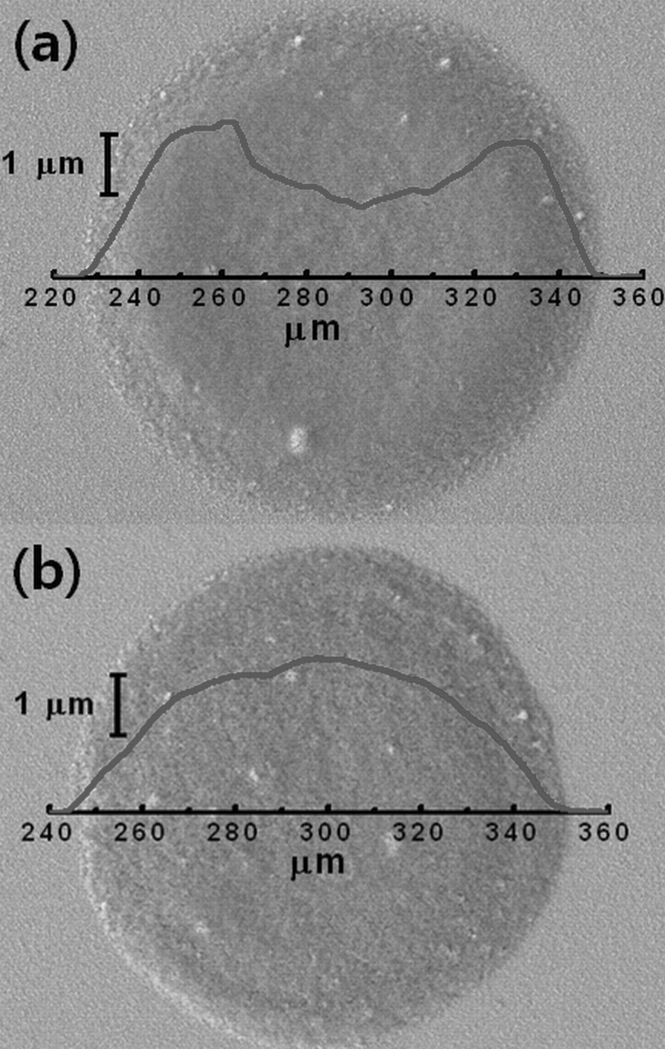
Figure 1. SEM images and surface profiles of TiO2 ink droplets: (a) single-solvent ink (water only) and (b) co-solvent ink (DMF+water).
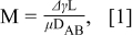
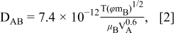
where Δγ is the surface tension difference between the center and contact line of the ink droplet, L is the radius of the ejected ink droplet on the substrate (55 μm), μ is the viscosity of the co-solvent ink, DAB is the diffusion coefficient in of DMF (solvent A) in water (solvent B).14 T is the temperature (333 K), ϕ is the association factor of the main solvent (2.6 for water), mB is the molecular weight of the main solvent (18 g/mol for water), μB is the viscosity of the main solvent (0.89 mPa-s) and VA is the molar volume of DMF (77.43 cm3/mol). The calculated DAB for TiO2 co-solvent ink is 1.39×10⁻⁹ m2/s. The Marangoni number for TiO2 co-solvent ink (20 vol% DMF + 80 vol% water) is calculated to be 1.75×10⁵. This number agrees to the values reported by other literatures for the creation of Marangoni flow.12,13 It suggests that the magnitude of Marangoni flow resulting from our TiO2 co-solvent ink is sufficient enough to uniformly deposit TiO2 nanoparticles on the surface during the evaporation of the ink droplets.
TiO2 line formation from ink droplets
The bond number represented in Eq. 3 determines whether the ink deposition follows a gravity-driven or a surface-tension-driven mechanism.15
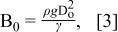
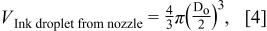
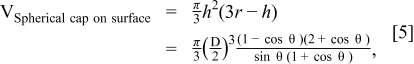
where ρ is the ink density, g is the gravity acceleration, Do is the diameter of the ink droplet, and γ is the surface tension. The calculated Bond number for TiO2 co-solvent ink is 3.15×10⁻³, indicating the surface tension interaction between the ink and the substrate plays an important role in determining the spreading of ink droplets on the substrate. It means that the shape of ink droplets on the substrate can be depicted by a geometric model, a spherical cap with various parameters described in Fig. 2. Since the initial volume of the ink droplet ejected from the nozzle should be identical to one of the spherical cap on the surface, the spreading ratio, β = D/Do, is expressed as in Eq. 6.
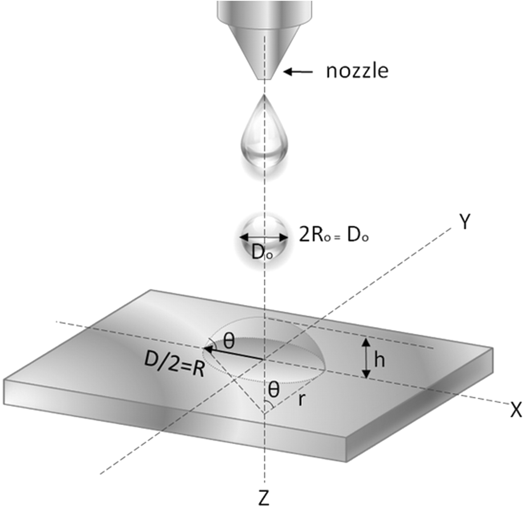
Figure 2. Geometric model of the ink droplet with spherical cap.

The calculated spreading ratio was compared to the experimentally measured one in Table t1. There is a reasonable agreement between two values, indicating the surface-tension-driven mechanism of ink deposition is appropriate in our TiO2 co-solvent ink.
Table I. Rheological properties (density and surface tension) of TiO2 co-solvent ink and its ink-droplet deposition related factors (contact angle, bond number, and spreading ratio).
| ρ | γ | Bo | θ | β | β | |
|---|---|---|---|---|---|---|
| Ink System | (Kg/m3) | (J/m2) | (×10−3) | (degree) | (calculated) | (measured) |
| 2 vol% TiO2 ink (20 vol% DMF + 80 vol% Water) | 1043 | 0.015 | 3.15 | 59 | 1.62 | 1.61 |
Since a series of ink droplets from the nozzle is coalesced into a printed line, the ink spreading ratio also affects the formation of lines by inkjet printing. A geometric model which correlates the ink spreading ratio to the line formation was proposed by Stringer et al. as in Eq. 7.15,16 This model also assumes that the entire volume of the inkjet-printed line is identical to the total volume of a series of ink-droplets ejected from the nozzle.
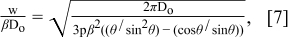
where w/βD0 is a dimensionless width defined in terms of Do, θ, and ink-droplet pitch (p). From this model, the maximum pitch, Pmax, between ink droplets to maintain a continuous line can be predicted since the line width can not be smaller than the diameter of the ink droplet on the substrate (D). In other words, Eq. 8 represents Pmax when w becomes D. In the case of TiO2 co-solvent ink, Pmax is predicted to be 109.9 μm from this model.
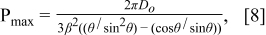
Figure 3 presents the dimensionless width of inkjet-printed TiO2 lines as a function of the ink-droplet pitch. Both the experimental data (red diamond) and the prediction from the geometric model (black solid line) are plotted together in Fig. 3. The images of TiO2 lines printed at different ink-droplet pitches are presented in Fig. 4. It is observed that the continuous lines began to form at the pitches from near Pmax (109.9 μm) to 50 μm. It means that our geometric model is well matched with the experimental results. However, as the ink-droplet pitch reduced to less than 40 μm, bulges were observed along the printed line. These bulges are a commonly observed in the inkjet printing process, especially at relatively small ink-droplet pitches.17 The further details on this bulging effect can be found from the study done by Duineveld.15
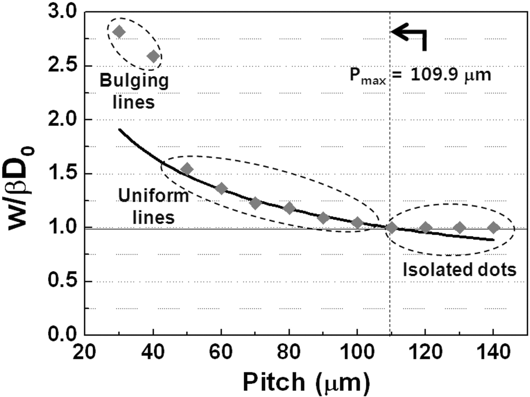
Figure 3. The dimensionless width of TiO2 lines printed at various ink-droplet pitches in comparison with the theoretical prediction obtained from Eq. 7.
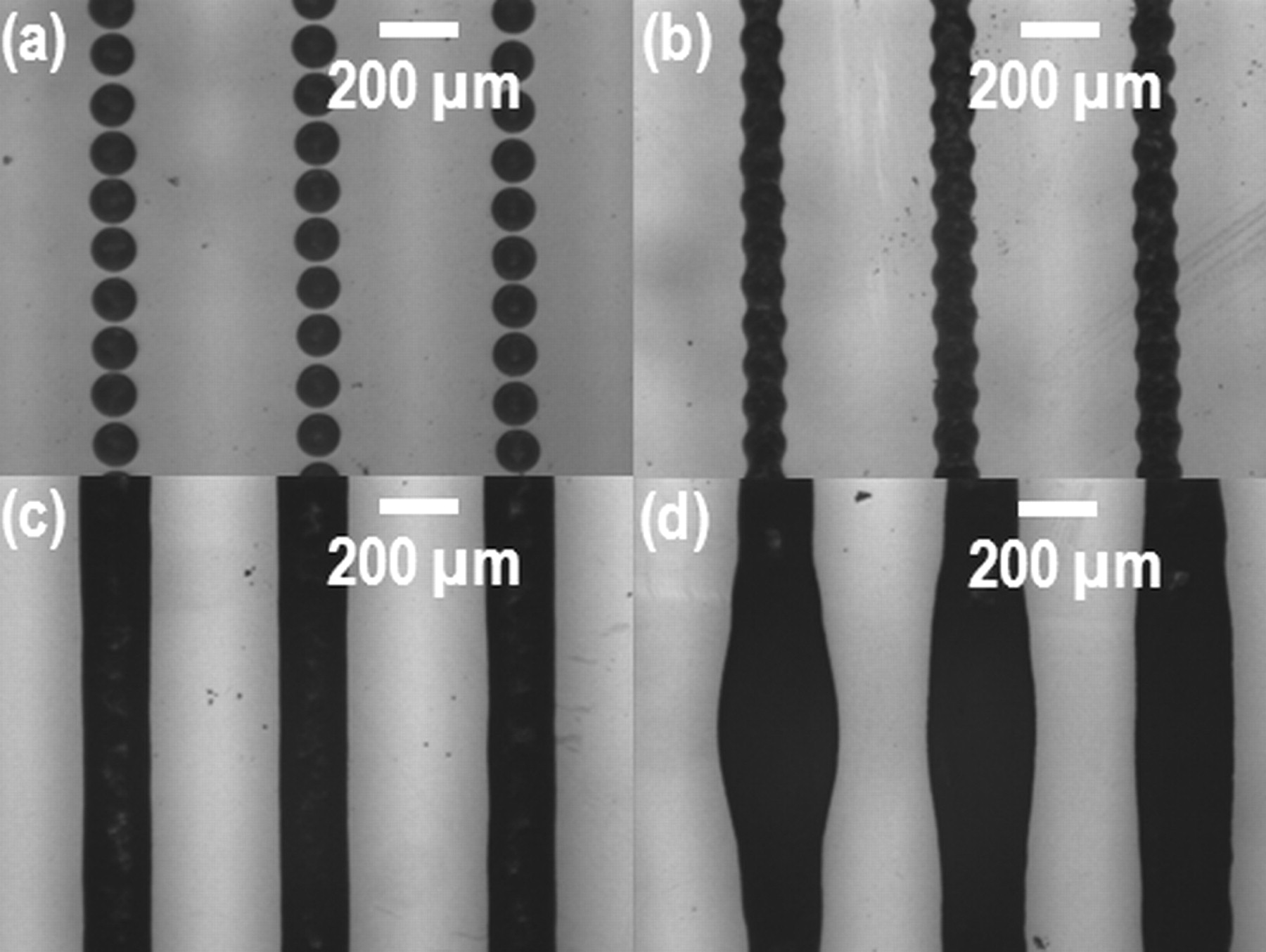
Figure 4. Images of the inkjet-printed TiO2 lines printed at different ink-droplet pitches: (a) ink-droplet pitch at 120 μm leading to the isolated dots, (b) ink-droplet pitch at 100 μm and (c) ink-droplet pitch at 50 μm showing a continuous line formation, and (d) ink-droplet pitch at 30 μm showing the line bulges.
Inkjet-printing of TiO2 films from the uniform lines
Since a film coating by inkjet printing comprises the overlapping of lines, the inkjet-printing of uniform dots and lines is prerequisite for the inkjet-printing of uniform films. We learned from the previous sections that the uniform TiO2 lines were printed at the ink-droplet pitch ranging from 50 μm to 100 μm with co-solvent ink. In order to print TiO2 films, we chose the ink-droplet pitch of 100 μm which led to the line width of 115 μm. With the fixed ink-droplet pitch, line-to-line pitches were varied from 100 μm to 10 μm. Since most of the TiO2 photoelectrodes for DSSCs with reasonable photovoltaic performance reported to be thicker than 5 μm,18–20 the line-to-line pitch of 20 μm was selected since it resulted in the film thickness close to 5 μm. The thickness of the TiO2 photoelectrode was increased up to 20 μm by repeating the inkjet-printing of the TiO2 film with increment of 5 μm per each printing step. The microstructure of the TiO2 photoelectrode after implementing four times of a single printing step was investigated by FE-SEM with FIB. Figure 5a and 5b show the surface morphology and cross-sectional image of the inkjet-printed TiO2 photoelectrode, respectively after the post-annealing at 450°C. From the relatively large area scan on the film surface in Fig. 5a, we confirmed that there were no cracks developed in the film during the inkjet printing process. Figure 5b indicates that the inkjet-printed TiO2 film has a significant amount of pores adequate for DSSC fabrication. It is also observed from Fig. 5b that the nanoparticles in the film are well connected by "necking" which enhances the electron transport through the photoelectrode and thus the performance of DSSC.
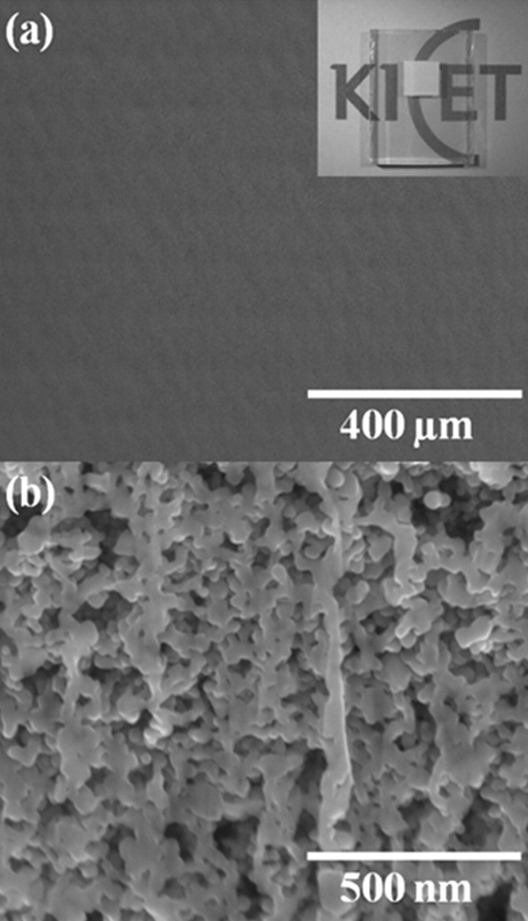
Figure 5. FE-SEM images of the inkjet-printed TiO2 film: (a) the surface morphology showing no cracks in the film. The inset presents the image of the inkjet-printed TiO2 photoelectrode on FTO glass (b) the cross-sectional image showing porous microstructure for dye absorption.
Application of the inkjet-printed TiO2 films to DSSCs
In order to investigate the optimum thickness of the inkjet-printed TiO2 films as the photoelectrodes for DSSC, four different thicknesses of the inkjet-printed TiO2 films were prepared to fabricate the conventional DSSCs. These inkjet-printed TiO2 films were annealed at 450°C for 30 min in the box furnace after the printing step. Figure 6 and Table 2 show that the photovoltaic properties of DSSCs as a function of the thicknesses of TiO2 photoelectrode films. It is noted that the photocurrent density (JSC) increases from 8.93 mA/cm2 to 12.79 mA/cm2 with increasing the thickness of TiO2 photoelectrode from 5 μm up to 20 μm. Over the same range of the thickness, on the other hand, the open-circuit voltages (VOC) and fill factors (FF) decreases from 0.73 V to 0.67 V and from 0.69 to 0.63, respectively. With these variations of JSC, VOC, and FF, the cell conversion efficiency (η) reaches the maximum value of 5.57% at the TiO2 thickness of 15 μm. The increase in Jsc with increasing the thickness of TiO2 photoelectrode is mainly related to the increase in the injected electrons from the excited dyes to the conduction band of TiO2, resulting from the increase in the surface area of TiO2 for dye absorption. However, the increase in the thickness of TiO2 photoelectrode enhances the probability of charge recombination between the injected electrons in TiO2 and the ions (I3−) in electrolyte, leading to the decrease in VOC.21
Table II. Comparison of photovoltaic performances among DSSCs fabricated with different thickness of the inkjet-printed TiO2 photoelectrode films.
| 5 | 8.93 | 0.73 | 0.69 | 4.51 |
| 10 | 10.71 | 0.70 | 0.67 | 5.07 |
| 15 | 12.66 | 0.69 | 0.64 | 5.57 |
| 20 | 12.79 | 0.67 | 0.63 | 5.42 |
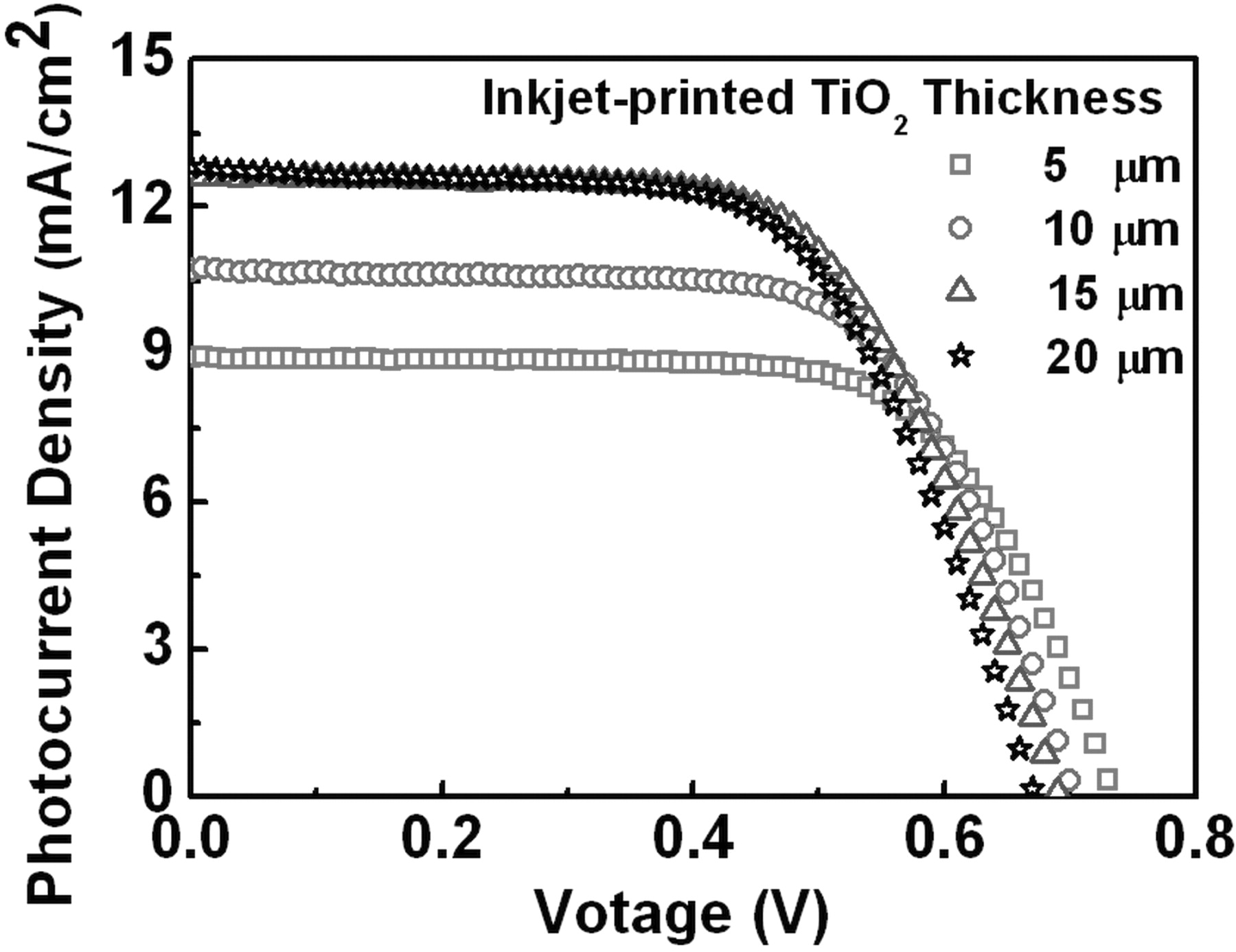
Figure 6. Photocurrent density – voltage characteristics depending upon the thickness variation of the inkjet-printed TiO2 photoelectrode films. The TiO2 photoelectrode films were annealed at 450°C.
Since the TiO2 co-solvent ink used in the entire fabrication of DSSCs had a relatively low viscosity (3.56 cPs), we tried to evaluate the feasibility of lowering the annealing temperature for the inkjet-printed TiO2 photoelectrodes. The thickness of the TiO2 photoelectrode was maintained at 15 μm in this experiment. Figure 7 and Table 3 show the detailed performance of DSSCs as a function of different annealing temperatures for the TiO2 photoelectrodes in the range from 150°C to 450°C. They present that JSC decreases as the annealing temperature decreases. It indicates that the connectivity among TiO2 nanoparticles in the photoelectrode is not completed at the temperature below 450°C.11,22 However, the DSSCs with the annealing temperatures of 250°C and 350°C still show the cell conversion efficiency of 2.55% and 4.08%, respectively. Although those cells show the lower cell conversion efficiencies than the cell fabricated at 450°C, the inkjet-printing of TiO2 photoelectrodes may contribute to the realization of DSSCs on plastic substrates. We are currently working on the improvement of the nanoparticles connectivity issue at the temperature below 250°C by infiltrating a connecting promoter through the photoelectrode.
Table III. Comparison of photovoltaic performances among DSSCs fabricated at different annealing temperatures for the inkjet-printed TiO2 photoelectrode films.
| 150 | 1.24 | 0.70 | 0.73 | 0.63 |
| 250 | 4.67 | 0.70 | 0.76 | 2.55 |
| 350 | 8.40 | 0.72 | 0.67 | 4.08 |
| 450 | 13.05 | 0.69 | 0.64 | 5.72 |
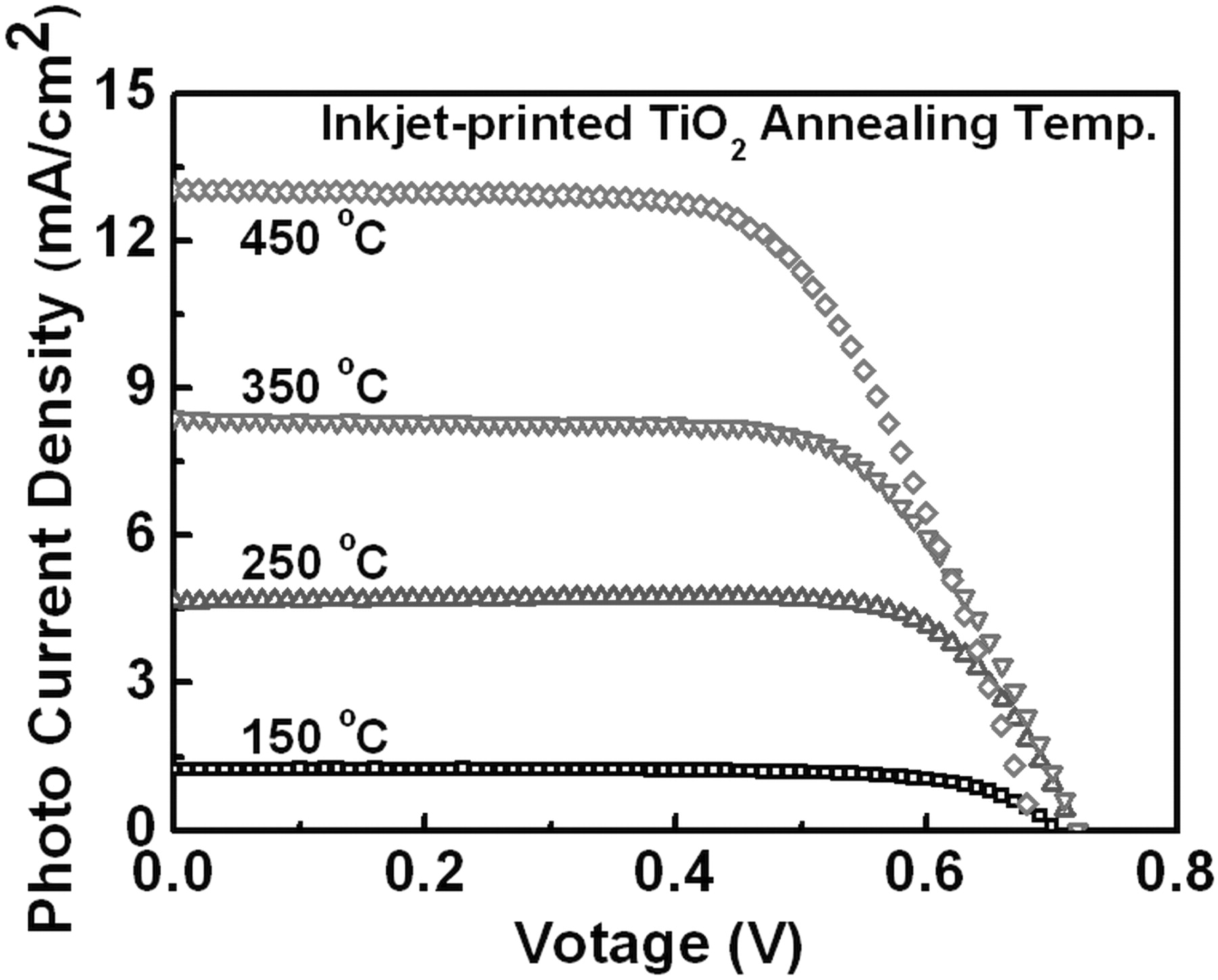
Figure 7. Photocurrent density – voltage characteristics of DSSCs with various annealing temperatures for the inkjet-printed TiO2 photoelectrode films. The film thickness is fixed at 15 μm.
Conclusions
In this paper, inkjet printing of TiO2 films was investigated. TiO2 co-solvent ink created a circulating flow within the ink droplet during its drying process, resulting in the formation of uniform lines and films by inkjet-printing. The theoretical model was introduced to predict the optical ink-droplet pitches (50 μm to 100 μm) for the inkjet-printing of uniform lines and well matched with the experimental results. Crack-free TiO2 films were printed on FTO glasses at the ink-droplet pitch of 100 μm and the line-to-line pitch of 20 μm and used as the photoelectrodes for DSSCs. The thickness of TiO2 photoelectrode was varied by increasing the number of the inkjet-printing of TiO2 films. With increasing the thickness from 5 μm to 20 μm, the cell conversion efficiency increases up to 15 μm and reaches its maximum value of 5.57%. The feasibility of reducing the annealing temperature for TiO2 photoelectrodes was also evaluated. Even though the best photovoltaic performance was observed from the TiO2 photoelectrode annealed at 450°C, the cells with TiO2 photoelectrodes annealed at 250°C and 350°C still showed the cell conversion efficiency of 2.55% and 4.08%, respectively. This study implies that inkjet printing can be one of the solutions to the fabrication of plastic DSSCs.
Acknowledgment
This research was supported by Small & Medium Business Administration (SMBA), Korea under Grant No. S1072318.