Abstract
We have developed high-performance double-layer (DL) hydrogen electrodes for reversible solid oxide cells. The DL hydrogen electrode consisted of mixed conductor, samaria-doped ceria (SDC), with highly dispersed Ni or Ni-Co nanocatalysts as the catalyst layer (CL) and, on top of it, a thin Ni−SDC cermet as the current collecting layer (CCL). The performance of the DL hydrogen electrode was appreciably improved by controlling the microstructure. The use of a thin, porous CCL increased the electronic conducting path to and from the CL, while maintaining sufficient gas-diffusion rates of H2 and H2O, and enlarging the effective reaction zone at the CL. The optimum CCL thickness was found to be 5 μm. The IR-free overpotentials η at the optimized DL hydrogen electrode in humidified hydrogen (p[H2O] = 0.4 atm) and Tcell = 800°C were 0.20 and −0.20 V at j = 0.5 and −0.5 A cm−2, respectively, indicating a highly reversible operation. The use of a full cell with the configuration of Ni0.9Co0.1/SDC DL hydrogen electrode|YSZ electrolyte|SDC interlayer|LSCF−SDC O2 electrode led to very promising results for the SOEC operation in which an IR-free electrolytic cell potential of 1.21 V at j = −0.5 A cm−2 and 800°C was achieved.
Export citation and abstract BibTeX RIS

This is an open access article distributed under the terms of the Creative Commons Attribution Non-Commercial No Derivatives 4.0 License (CC BY-NC-ND, http://creativecommons.org/licenses/by-nc-nd/4.0/), which permits non-commercial reuse, distribution, and reproduction in any medium, provided the original work is not changed in any way and is properly cited. For permission for commercial reuse, please email: oa@electrochem.org.
Nowadays, hydrogen is attracting much attention as an energy carrier suitable for long-term and large-scale storage. Electrolysis of water is one of the effective technologies to produce pure hydrogen in a single step. Among the various types of electrolysis cells, solid oxide electrolysis cells (SOECs) operating at high temperature (800–1000°C) present the highest conversion efficiency due to favorable thermodynamic and kinetic conditions.1–7 An SOEC can be operated in reverse mode as a solid oxide fuel cell (SOFC) that directly converts the chemical energy in hydrogen gas into electrical energy with a high energy conversion efficiency. Thus, a reversible solid oxide cell (R-SOC) is regarded as an efficient reciprocal energy converter between hydrogen and electricity.8–12 Since the pioneering work in late 1960s to nowadays, the materials commonly used in SOFCs have been swiftly adopted in SOECs, i.e., yttria-stabilized zirconia (YSZ) electrolytes, Ni-YSZ cermet hydrogen electrodes, and perovskite-type oxygen electrodes based on La1−xSrxMnO3−δ (LSM) or La1−xSrxFe1−yCoyO3−δ (LSCF).1–11 However, it is very important to develop high-performance electrodes for R-SOC as clearly demonstrated by recent modeling or calculation.9,12 The essential factors for improving electrode performance are a high electrocatalytic activity and an extended effective reaction zone (ERZ).9,13 The ERZ is located around the physical triple phase boundary (gas/oxide ion conductor/electronic conductor). In the case of Ni-YSZ cermet hydrogen electrode, for example, the polarization performance (the extension of the ERZ) strongly depends on the electrode microstructure (size and distribution of Ni and YSZ, their connectivity, thickness and porosity), which is closely related to the fabrication process.14,15
Mixed ionic and electronic conductors (MIECs) such as rare-earth doped ceria are potential candidates for the hydrogen electrode of SOEC/SOFC due to the considerable enlargement of the ERZ. The use of MIEC, La- or Y-doped ceria, in the SOFC anode has been first reported by Takahashi et al.: the anodic overpotential at the doped-ceria anodes was reduced considerably at 1000°C without any metal catalysts.16 Intending to achieve high-performance at a medium temperature around 800°C, the concept of a catalyzed-MIEC, e.g., porous samaria-doped ceria (SDC) with a highly dispersed metal catalyst on its surface for SOFC anode, was proposed and examined in our laboratory for the first time.17 This idea has been adopted by many research groups and the term "infiltrated-electrode" is now widely used. We have demonstrated that nm-sized metal electrocatalysts highly dispersed on the SDC exhibited high performance in both SOFC and SOEC modes at reduced temperatures.13,17–23 Both the ionic conductivity σion and the electronic conductivity σe in the mixed-conducting SDC are quite high at high temperatures (>800°C) in a humidified H2.24 The SDC with a small amount of Ni-based catalyst provides a high ionic and electronic conductive network and sufficiently enhances the ERZ. The performances of such SDC electrodes in both operation modes were found to be improved by decreasing the particle size of Ni or Ni-Co,1920,22 indicating that active sites are formed at the boundary between the Ni or Ni-Co nanoparticles and the SDC surface.
However, both σion and σe decrease with lowering the operating temperature since the transport of oxide ions to positions beyond the electrolyte interface becomes difficult. In other words, the ERZ is restricted to the SDC electrode layer close to the solid electrolyte,25 where the effective gas transfer (hydrogen and water vapor) through the micropores plays a pivotal role. In 2007, we proposed the concept of double-layer (DL) electrode,26 as schematically shown in Fig. 1 for SOEC cathode as an example. The SDC with highly dispersed Ni or Ni-Co catalysts was employed as the catalyst layer (CL) to enlarge the ERZ. The porosity of the CL was kept relatively low in order to increase the σion and the σe. The current collecting layer (CCL), Ni−SDC cermet (with μm-size Ni), was formed on top of the CL to provide a high σe and high gas-diffusion rates from the separator (interconnect) to the CL. The electronic conductive micrometer-sized network of the CCL helps to establish an intimate contact with the CL, which is hardly achieved by just direct contact of the CL with the interconnect that has mm-size ribs and channels. We expect that the minimized ohmic loss and the increased gas-diffusion rates by the use of the CCL will contribute to enlarge the ERZ. It is important to notice that the performance of the DL electrode is certainly enhanced by controlling the dispersion state and the amount of Ni-based catalysts in the CL, the volume fraction of Ni in the CCL, the porosity and thickness of each layer.27 Based on a similar concept, we have also succeeded in developing DL oxygen electrodes, consisting of La0.6Sr0.4Co0.2Fe0.8O3 (LSCF) with 40 vol.% SDC as the CL (interfaced to SDC interlayer/YSZ electrolyte) and an LSCF CCL. The DL oxygen electrode so constructed exhibited higher performance than the single-CL electrode.28
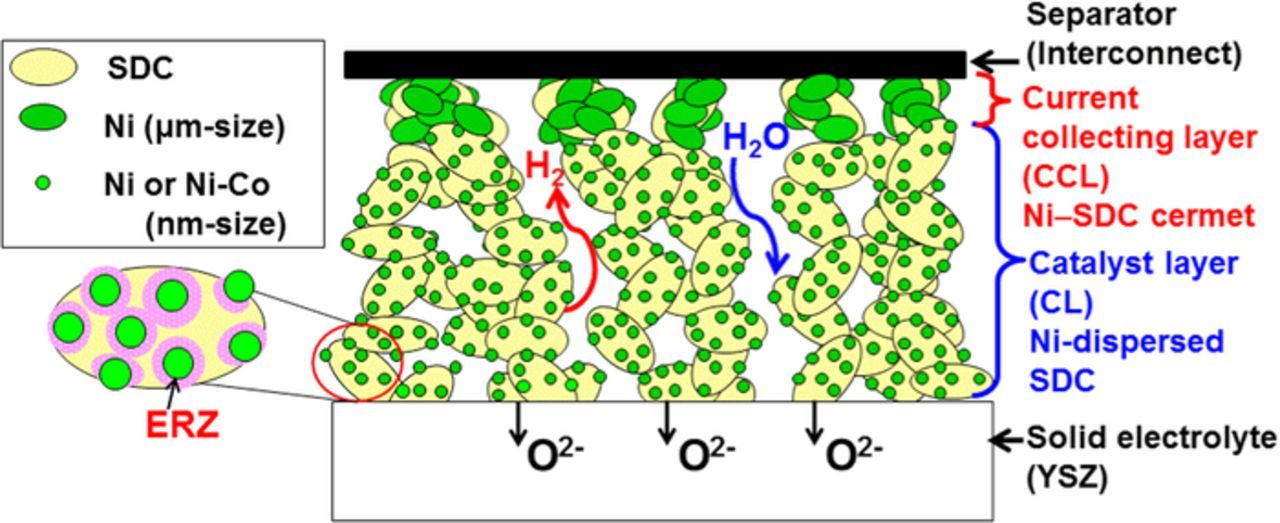
Figure 1. Schematic representation of double-layer (DL) hydrogen electrode composed of highly-dispersed Ni/SDC as a catalyst layer (CL) and Ni–SDC cermet as a current collecting layer (CCL).
In the present work, we demonstrate that the microstructure of the DL hydrogen electrodes plays an important role in decreasing the ohmic and polarization losses under reversible SOEC/SOFC operation at 800°C.
Experimental
Single cell fabrication
Because the objective of this research was to evaluate the specific performance of the DL hydrogen electrodes, we employed an electrolyte-supported cell with well-defined electrode geometry (electrode area). A commercial 8 mol% yttria-stabilized zirconia disk (8YSZ, 13 mm in diameter and 0.5 mm in thickness, Japan Fine Ceramics Co., Japan) was used as the solid electrolyte for a single cell fabrication. First, a thin layer of SDC (ca. 1 μm in thickness) was attached onto the YSZ electrolyte surface, which acted as an anchoring layer.13,18,19 A porous scaffold of SDC, (CeO2)0.8(SmO1.5)0.2, was prepared onto the SDC layer in the same manner as in our previous work.19 To control the porosity of the SDC scaffold, fine polymer beads (PMMA, d = ca. 1 μm) were added as a pore-former in the paste: the polymer beads were decomposed to form μm-sized pores during firing of the scaffold in air at 1150°C for 4 h.25
A paste of NiO−SDC (60 vol.% Ni) was prepared by ballmilling commercial NiO powder (Kanto Chemical Co. Inc., Japan), SDC powder and pore-formers (PMMA or carbon black (SB220, Asahi Carbon, Co. Ltd., Japan) in 40 vol.% ethanol-water mixture. NiO−SDC CCL was prepared by tape-casting the paste on the top of the SDC scaffold, followed by firing at 1150°C for 4 h. A nickel nitrate solution or a mixed solution of Ni(NO3)2 and Co(NO3)2 was impregnated into the CL through the CCL, followed by heat-treatment at 400°C for 30 min to form NiO or Ni0.9Co0.1O (atomic ratio) nanoparticles. The Ni or Ni0.9Co0.1 catalyst loading in the CL was adjusted at 8 vol.%.22 Microstructure of the electrodes thus prepared was observed by a scanning electron microscope (SEM, S-5200, Hitachi Co., Japan) equipped with an energy-dispersive X-ray spectrometer (EDX, Genesis 4000, CDU detector, Ametek Inc., USA).
The test cells were prepared with the following configuration:
DL H2 electrode|YSZ (0.5 mm)|SDC interlayer|O2 electrode
The oxygen electrode employed was porous Pt or a composite of LSCF with 40 vol.% SDC. Details of the preparation method of LSCF−SDC electrode with SDC interlayer are given in our recent work.29 The projected area of both H2 and O2 electrodes was 0.28 cm2. As a Pt/air reference electrode (ARE), a Pt wire was wrapped along the lateral of the YSZ electrolyte disk and fixed with Pt paste.
The apparent porosities of the CL (PCL) and the CCL (PCCL) were calculated by the following equations,
![Equation ([1])](https://content.cld.iop.org/journals/1945-7111/164/9/F889/revision1/d0001.gif)
![Equation ([2])](https://content.cld.iop.org/journals/1945-7111/164/9/F889/revision1/d0002.gif)
where VPore, VSDC, VNi, VCL, and VCCL are the volumes of the pores, SDC, Ni, CL, and CCL, respectively. The values of VSDC and VNi were calculated as mSDC/ρSDC and mNi/ρNi, in which mSDC and mNi are the masses of SDC and Ni loaded and ρSDC and ρNi are the densities of SDC (7.12 g cm−3) and Ni (8.85 g cm−3), respectively. The values of VCL and VCCL were the product of the electrode area (A, 0.28 cm2) and the thickness of CL (LCL) and CCL (LCCL), evaluated by SEM observation of the electrode layer prepared in the same manner. The values of PCL and PCCL thus calculated were ca. 60% and 70%, respectively.
Electrochemical measurement
The set-up for the test cell for reversible SOEC/SOFC was described in our previous report.19 The test cell was sealed with a gold ring. The DL H2 electrode was reduced in humidified hydrogen at Tcell = 800°C for 30 min prior to the performance evaluation. The area-specific ohmic resistance and steady-state IR-free polarization characteristics of the H2 electrodes were measured at Tcell = 800°C by the current interruption method in a three-electrode configuration with humidified hydrogen (p[H2O] = 0.4 atm, H2 flow rate = 30 cm3 min−1) while supplying dry O2 at 30 cm3 min−1 to the counter electrode. The utilization of water vapor in the SOEC operation mode was ca. 10% at 1 A cm−2. A current-off pulse of 100 ms-width was applied from a current-pulse generator (NPGS101-2A, Nikko Keisoku Ltd., Japan) and the resulting potential responses were recorded with a storage oscilloscope (VC-6045, Hitachi Co., Japan).
All of the I–E curves were obtained at steady-state after the test cells were conditioned by repeating galvanostatic load cycles at Tcell = 800°C as follows. First, the current density j was increased from 0 to 0.88 A cm−2 (0.25 A for hydrogen oxidation current) at the sweep rate of 10 mA s−1, followed by holding for 10 min. Then, the j was decreased from 0.88 A cm−2 to 0 at the identical sweep rate, and held for 10 min (open circuit condition). This trapezoid-shaped current-time protocol was applied again. Next, the trapezoid-shaped current-time protocol was repeated twice between 0 and −0.88 A cm−2 (−0.25 A for hydrogen evolution current) with the same holding time. By conducting these conditioning steps, the electrode potential and the ohmic resistance reached stable values within 15 min after changing the j in the polarization measurement.
Since local heat evolution within the electrode reduces not only the ohmic resistance but also the overpotential, a careful monitoring of ohmic resistance, which is sensitive to the Tcell, is very important. We checked the ohmic resistance of the cell in the whole current density range examined to confirm that the relationship between the IR loss and current density was completely linear at a given Tcell.
Results and Discussion
Microstructure of double-layer hydrogen electrode
Figure 2 shows cross-sectional images of the DL hydrogen electrode with Ni catalyst in the CL. A clear difference was observed between the microstructure of relatively dense CL (8 vol.%-Ni/SDC) and CCL (60 vol.% Ni−SDC cermet) with larger porosity. The CL and CCL were well adhered and the thickness of each layer was quite uniform: 15 μm for the CL and 10 μm for the CCL. The apparent porosities based on Eqs. 1 and 2 were calculated to be ca. 60% for the CL and ca. 70% for the CCL. We intended to prepare such a highly porous CCL in order to increase not only the gas-diffusion rate but also the penetration rate of the Ni(NO3)2 solution for the impregnation of Ni catalyst into the CL. As shown in the high magnification image of the CL (Figure 2b), nano-sized Ni particles with the average size of 46 nm were uniformly dispersed on the SDC support, indicating the success of the catalyst impregnation penetrating through the porous CCL, although, unavoidably, only a small fraction of Ni catalysts were found to deposit on the SDC surface in the CCL (Figure 2c). Elemental distribution of Ni and Ce components in the DL electrode is shown in Figure 3. The boundary between the CCL and the CL was distinctly observed as a change in Ni concentration, but a good connection of Ni at the interface was also seen, which may enable electronic percolation from the CCL to CL.
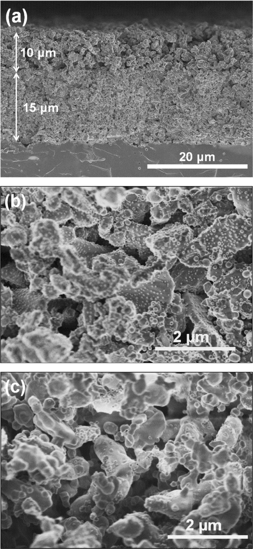
Figure 2. SEM cross-section images of (a) DL hydrogen electrode consisting of (b) SDC scaffold with highly dispersed Ni (8 vol.%) as a CL and (c) Ni–SDC cermet (60 vol.% Ni) CCL. All samples were reduced at 800°C for 30 min.
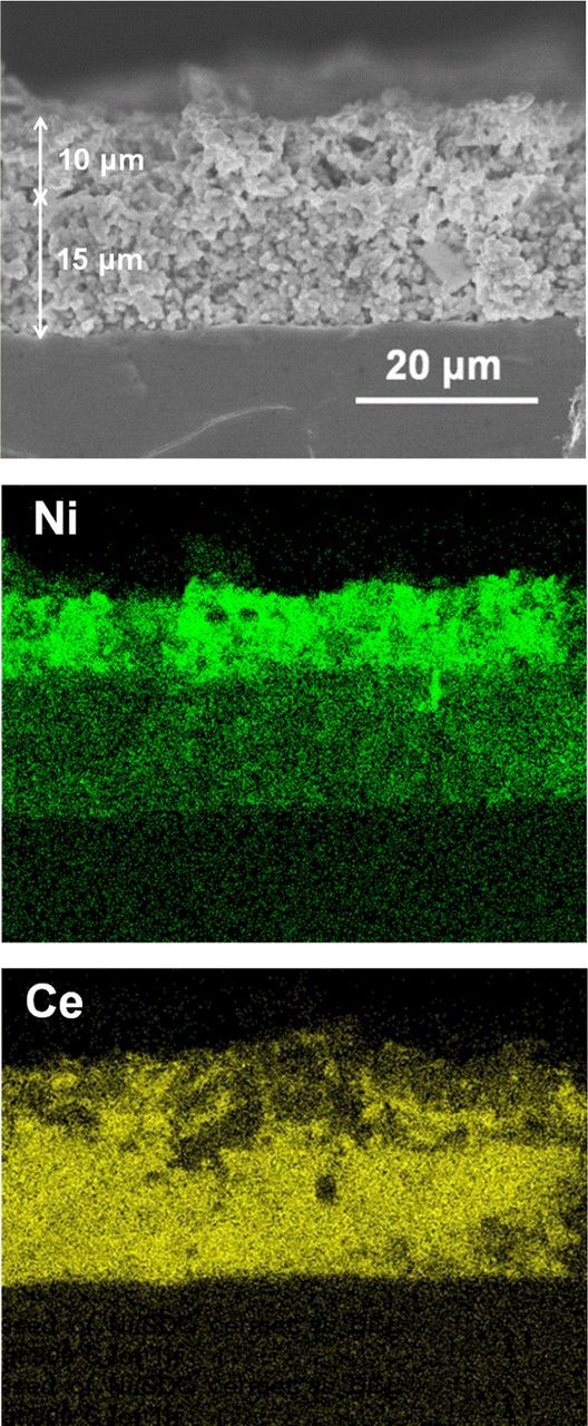
Figure 3. SEM image and elemental distribution maps of Ni and Ce for a cross-section of DL hydrogen electrode shown in Fig. 2.
Effect of microstructure of Ni−SDC CCL on the performance of DL hydrogen electrode
Effect of microstructure of Ni−SDC CCL on the electrode performance was examined by the use of two different pore-formers in the NiO−SDC paste: PMMA and carbon black (CB). The thickness and the porosity of the CCLs were maintained nearly identical (9 to 10 μm and ca. 70%) by adjusting the pastes irrespective of the pore-formers. Figure 4 shows steady-state IR-free polarization curves (I -- E curves) at 800°C for the DL hydrogen electrodes with the two CCLs described above. The anodic I -- E curve (hydrogen oxidation in SOFC operation) was measured first, followed by the cathodic polarization (hydrogen evolution in SOEC operation). We repeated the anodic and cathodic polarizations and found no significant difference in both measurements. It was found that the DL hydrogen electrode with the CCL prepared with CB pore-former exhibited much higher performance in IR-free anodic and cathodic polarizations than that with PMMA pore-former, whereas the ohmic resistances of both cells were comparable.
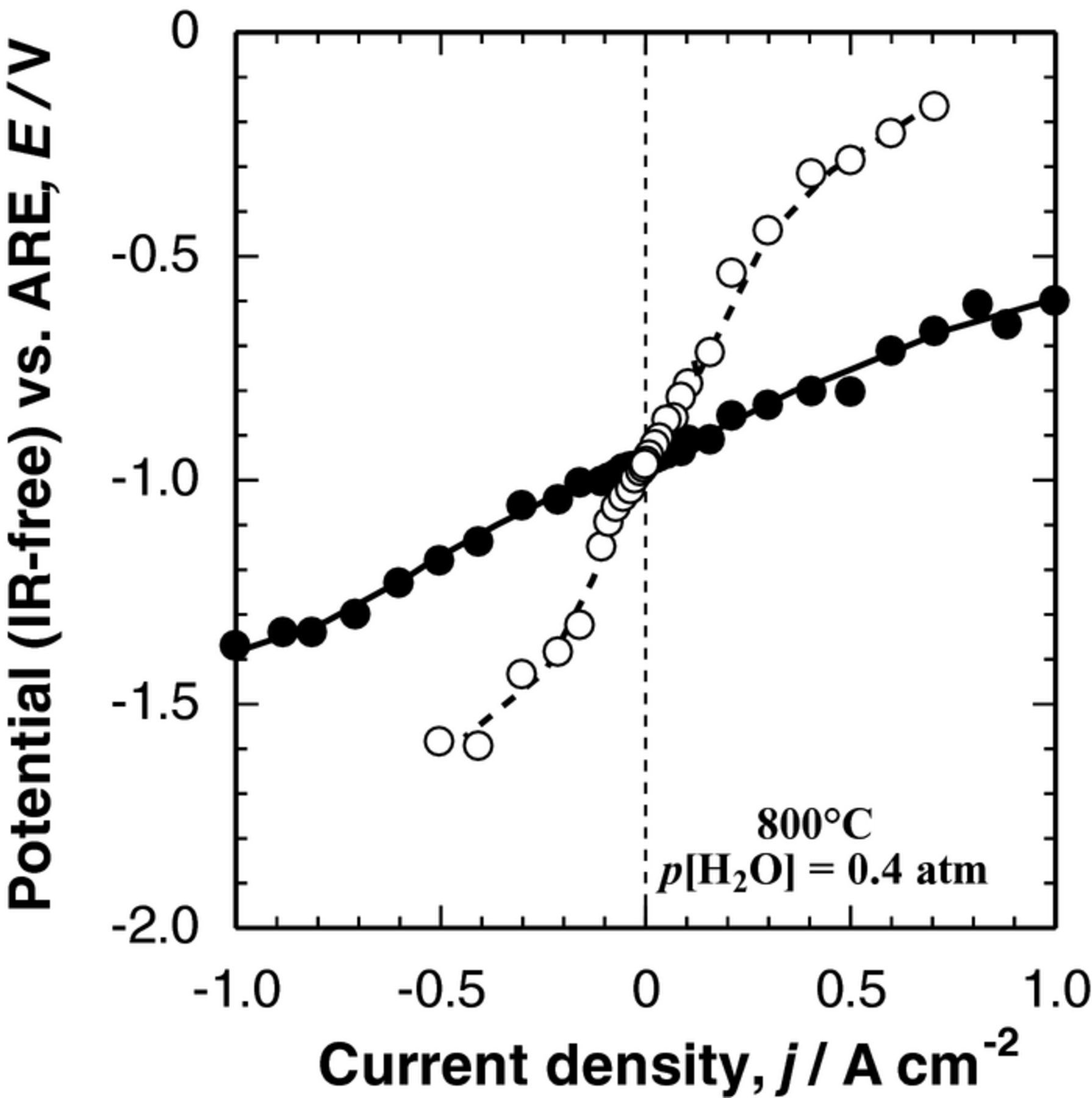
Figure 4. Polarization curves (IR-free I--E curves) of DL H2 electrodes, in which PMMA (○) or carbon black (CB, ● symbol) was used as the pore-former for Ni–SDC CCL, measured in H2 + H2O (p[H2O] = 0.4 atm) at Tcell = 800°C. Ni (8 vol.%)-dispersed SDC was used as the CL.
Next, we focused on the differences in performances of the two electrodes. First, as a measure of the electrocatalytic activity, the exchange current density (j0) was calculated from the polarization resistance Rp (= dE/dj) at low overpotential (η).18–21 Since good linear relationships were obtained between η and j for |η| < 0.02 V, j0 was calculated by the following equation,
![Equation ([3])](https://content.cld.iop.org/journals/1945-7111/164/9/F889/revision1/d0003.gif)
where n is the number of electrons transferred in the reaction and R, T, and F have their usual meanings. We assumed n to be 2, considering the following reaction,
![Equation ([4])](https://content.cld.iop.org/journals/1945-7111/164/9/F889/revision1/d0004.gif)
where [Ni/SDC] denotes the active site formed at the boundary of Ni catalysts and SDC particle surfaces mainly in the CL. As shown in Table I, the value of j0 thus calculated for a DL Ni/SDC hydrogen electrode with the CCL prepared with CB pore-former was 0.11 A cm−2, which is about five times larger than that with PMMA pore-former (0.02 A cm−2). The increase in j0 indicates the extension of the ERZ.
Table I. Exchange current density, j0, and ohmic resistance, RH2-side of DL H2 electrode, in which PMMA or carbon black (CB) was used as the pore former for the Ni–SDC CCL, measured in p[H2O] = 0.40 atm at Tcell = 800°C.
| Pore former for Ni–SDC CCL | Exchange current density, j0 / A cm−2 | ohmic resistance, RH2-side / Ω cm2 |
|---|---|---|
| PMMA | 0.02 | 1.67 |
| CB | 0.11 | 1.57 |
Then, we examined the differences in the microstructure of two electrodes by SEM. Figure 5 shows cross-sectional images of two DL Ni/SDC electrodes with the identical CL and different CCLs described above. The thickness (15 μm), porosity (60%), and the dispersion state of Ni catalysts were confirmed to be unchanged in the two electrodes: nearly identical images were observed, as shown in Fig. 2. It was found that the thickness of both Ni/SDC CCLs was uniform (9 to 10 μm) and the apparent porosities of the CCLs were calculated to be 66% and 67% in the case of pore-formers of PMMA and CB, respectively. A careful inspection of several high-magnification images of the CCLs indicated that the micro-pores formed by CB tended to connect with each other, compared with those formed by PMMA, while the thickness and apparent porosity of the two CCLs were comparable. Such a difference in the connection of micro-pores can be ascribed to the morphology of pore-formers: PMMA (ca. 1 μm) particles did not adhere to each other, while CB (primary particle size = ca. 30 nm) particles aggregated to form an agglomerate (branched network, a few μm in apparent diameter). The formation of micro-pores with better connection might increase the gas-diffusion rate through the CCL. It has been reported that an increased gas-diffusion rate in electrode layers usually improved the I--E performance, specifically at high current densities.30,31 Effectively, in the present work, we have found that the increase in the gas-diffusion rate in the CCL greatly improved the performance of the DL hydrogen electrode with the identical CL over the whole current density region examined. Hereinafter, we have employed CB as the pore-former in the CCL.
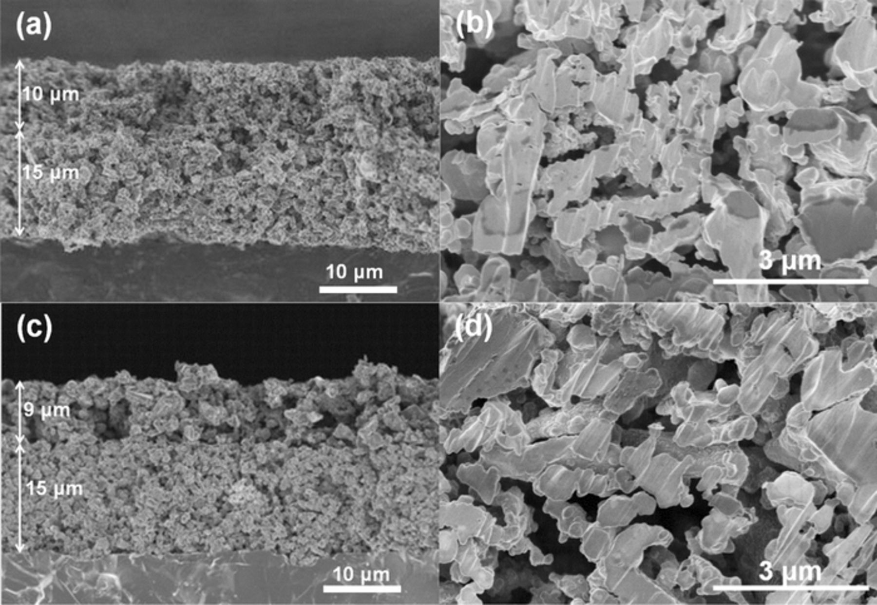
Figure 5. Cross-sectional SEM images of DL hydrogen electrodes (a, c) and high-magnification images of Ni–SDC CCL (b, d). The pore former for the CCL used was PMMA (a, b) and CB (c, d). Two kinds of DLs were reduced at 800°C for 30 min.
Effect of Ni−SDC CCL thickness on the performance of DL hydrogen electrode
Next, we examined the effect of Ni−SDC CCL thickness on the performance of the DL hydrogen electrode, in which Ni0.9Co0.1 catalysts23 with higher activity than Ni were highly dispersed in the CL. The counter electrode used was LSCF−SDC. Figure 6 shows typical SEM images of DL hydrogen electrodes with CCL thicknesses from 5 to 20 μm. A SEM image of the single CL without CCL is also shown for comparison in Figure 6a. The CCLs formed on the CL were found to be uniform in the thickness with apparent porosity of ca. 70%, irrespective of the thickness. The thickness of all CLs ranged from 14 to 16 μm with the porosity of ca. 60%. Figure 7 shows steady-state IR-free I−E curves of the DL hydrogen electrodes measured in the reversible SOEC/SOFC operation modes at 800°C. It was clearly found that the thickness of the CCL had a significant effect in reducing the polarization loss. The DL hydrogen electrode with 5 μm-CCL exhibited the highest performance in both cathodic and anodic operations. For example, the IR-free cathode potential at j = −0.5 A cm−2 (hydrogen evolution in SOEC mode) was about −1.16 V vs. air reference electrode (ARE), which corresponds to an overpotential of −0.20 V, while the anodic η at j = 0.5 A cm−2 (hydrogen oxidation in SOFC mode) was 0.20 V. Thus, a high degree of reversibility has been achieved.
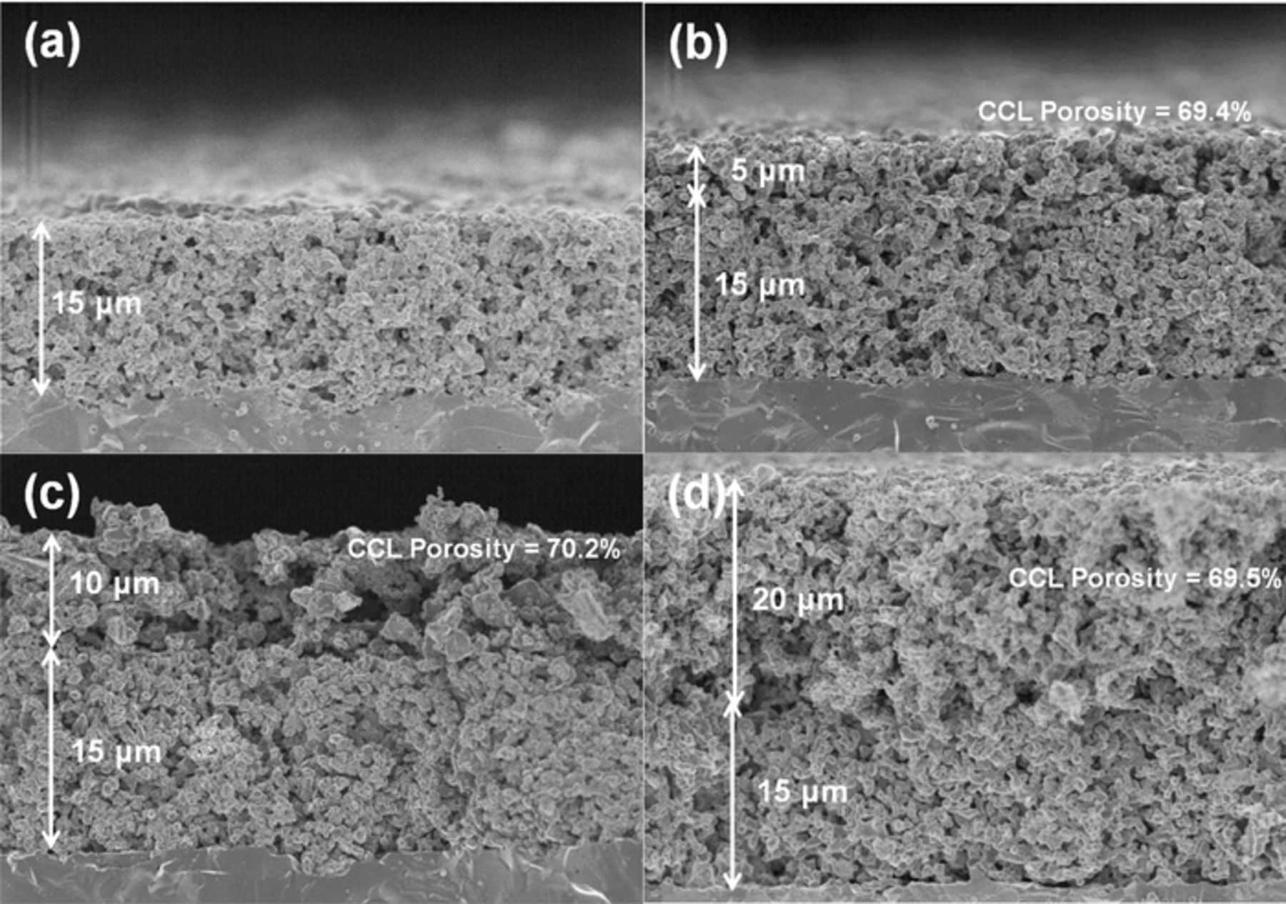
Figure 6. Cross-sectional SEM images of DL hydrogen electrodes, in which the Ni–SDC CCL with the thickness of (b) 5 μm, (c) 10 μm, and (d) 20 μm was prepared onto the Ni0.9Co0.1/SDC CL. Image (a) is the CL without CCL as a reference. All samples were reduced at 800°C for 30 min.
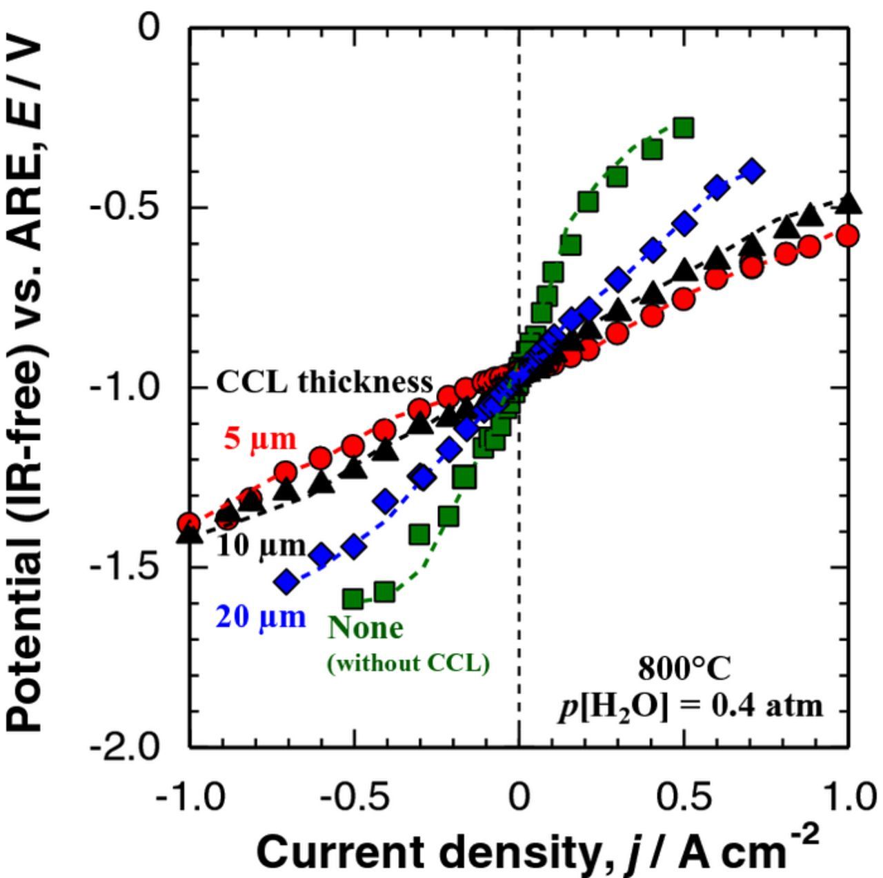
Figure 7. Polarization curves (IR-free I--E curves) of the DL hydrogen electrodes (shown in Fig. 6) measured in H2 + H2O (p[H2O] = 0.4 atm) at Tcell = 800°C. Thickness of CCL: (a) zero (without CCL) ( ), (b) 5 μm (
 ), (c) 10 μm (
 ), and (d) 20 μm (
 ).
).
We have also analyzed the effect of the CCL thickness on the electrode performance and the ohmic resistance. As shown in Fig. 8a, the current densities j at the IR-free η of 0.1 V and −0.1 V, |j@0.10 V|, showed the maximum value of ca. ±0.3 A cm–2 at 5 μm-CCL in both anodic and cathodic operation modes. We expect that the thin CCL with high electronic conductivity can act as a μm-size current collector to minimize the ohmic loss between the interconnect (Pt mesh in this experiment) and the CL. Figure 8b shows the area-specific ohmic resistances of the DL hydrogen electrode side RH2-side, measured by the current interruption method with the use of the ARE. The values of RH2-side for the DLs were indeed smaller than that without the CCL, and they reached a minimum value of 0.7 Ω cm2 at the 5 μm-CCL. The RH2-side may consist of the area-specific ohmic resistances of the Ni–SDC CCL (RCCL), the Ni0.9Co0.1/SDC CL (RCL), a part of YSZ electrolyte (RYSZ, from the equivalent potential plane of the ARE), and the contact resistances between them. The RCL could be considered unchanged irrespective of the CCL thickness, since the CLs were prepared on the YSZ disk in the same manner. Because the RCCL values were negligibly small even with the thickness and the porosity described above, such a change seen in RH2-side (Fig. 8b) was ascribed predominantly to the change in the contact resistance at the CCL/CL interface. Therefore, it is inferred that the whole Ni0.9Co0.1/SDC-CL can work effectively by the use of 5 μm-CCL as micrometer-size current collector. The minimum ohmic resistance of this cell was approximately equal to the RYSZ value, which was measured in the cell configuration of Pt|YSZ|Pt, indicating negligibly small ohmic resistances of both the optimized DL hydrogen electrode and the LSCF−SDC oxygen electrode (including the contact resistance). In contrast, the contact resistance between the single-CL (without CCL) and the metal (Pt) mesh current collector should be larger. However, a further increase in the CCL thickness (≥10 μm), in turn, additionally increased the RCCL. Moreover, the gas-diffusion rate through the CCL is presumably slowed down by increasing the CCL thickness. Thus, the 5 μm-CCL provides the best balance in enlarging the ERZ by an effective transport of gases (H2O, H2) and an effective electronic conductive network.
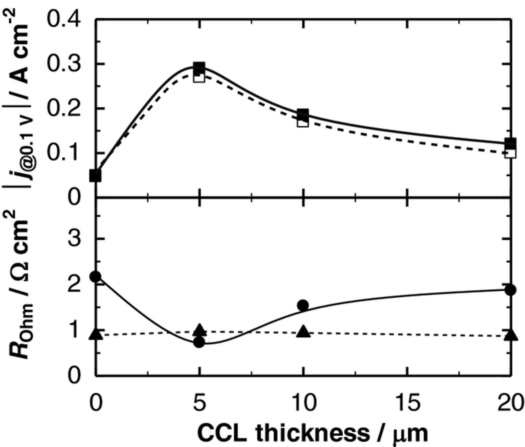
Figure 8. Dependence of current density at overpotential |η| = 0.10 V, |j@0.10 V|, and ohmic resistances (DL hydrogen electrode side (RH2-side, ●) and oxygen electrode side (RO2-side, ▲)) on the CCL thickness for the I--E measurement shown in Fig. 7. |j@0.10 V|: hydrogen oxidation (□), hydrogen evolution (■).
Finally, with the use of the optimized DL hydrogen electrode and LSCF−SDC oxygen electrode, a full cell performance was examined at 800°C. As shown in Fig. 9, almost linear I−E curves were obtained for hydrogen and oxygen electrodes, indicating a highly reversible operation. The electrolytic cell potential Ecell of 1.21 V (IR-free) was achieved at j = −0.5 A cm−2 and 800°C with p[H2O] = 0.4 atm (cathode) and pure O2 (anode). To estimate the actual cell performance, we need to add the ohmic loss of the cell (predominantly that of the solid electrolyte) to the IR-free potential stated above. Taking the ohmic loss of the solid electrolyte of scandia-stabilized zirconia with a thickness of 50 μm (46 mΩ cm2 at 800°C) into account,32 a promising Ecell value of 1.23 V was calculated. Nonetheless, it is quite difficult to compare our performance with those reported for electrode-supported cells in the literature, since the YSZ electrolyte thin film penetrated into the porous electrode (such as Ni-YSZ) support, resulting in good adhesion and a large electrolyte/electrode interfacial area. In contrast, such a phenomenon is unlikely to be seen in the electrolyte-supported cell employed in the present research (see Figs. 5 and 6). It is also noticed that air is usually used as the anode carrier (sweep) gas, leading to a reduced open circuit potential by ca. 36 mV. A more reasonable comparison, however, can be done for an electrolyte-supported cell stack (Ni-ceria|YSZ|La-Co-Fe oxide). The Ecell was reported to be ca. 1.35 V at j = −0.3 A cm−2 and 800°C with p[H2O] = 0.37 atm and air (anode).33 In the present work, by using a small single cell, we have clearly demonstrated a very promising full cell performance. Durability tests of the full cell, as well as large cell testing, are in progress in our laboratory.
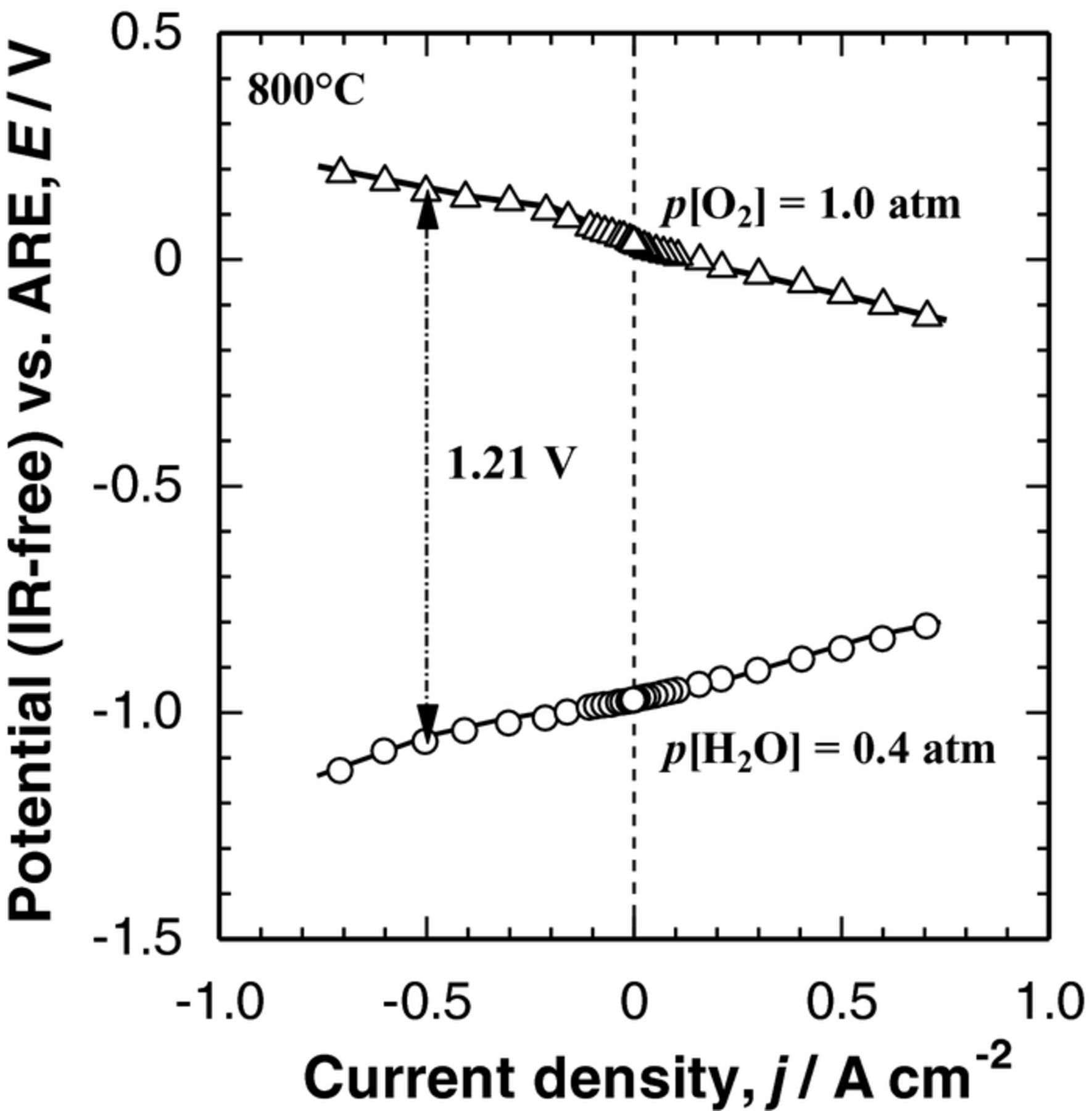
Figure 9. Polarization curves (IR-free) of DL H2 electrode and LSCF–SDC O2 electrode, with a configuration of [H2O + H2, Ni0.9Co0.1/SDC DL H2 electrode|YSZ electrolyte| SDC interlayer LSCF−SDC O2 electrode, O2] at Tcell = 800°C.
Conclusions
We have demonstrated high applicability of a double-layer Ni/SDC hydrogen electrode consisting of Ni−SDC cermet as a CCL, and of a highly-dispersed Ni-Co catalyst in a SDC scaffold as a CL in SOEC/SOFC reversible operations. The noticeable increase in the performance can be explained by the substantial decrease in both ohmic and polarization losses achieved by controlling the microstructure of Ni−SDC CCL, i.e., 1) by optimizing porosity (70% with the use of aggregated carbon black as the pore-former) to facilitate gas-diffusion toward the effective reaction zone (ERZ) and 2) by optimizing the CCL thickness (5 μm) so as to provide the best balance in enlarging the ERZ to achieve effective gas-diffusion together with effective electronic conducting path. The IR-free electrolytic cell potential of 1.21 V was achieved at the current density of −0.5 A cm−2 in SOEC operation at 800°C.
Acknowledgments
This work was supported by funds for Advanced Low Carbon Technology Research and Development Program (ALCA) from Japan Science and Technology Agency (JST). A part of this work was presented at the 14th International Symposium on Solid Oxide Fuel Cells (SOFC-XIV), Glasgow, Scotland (July 26–31, 2015).