
Abstract
A series of electrolyte formulations containing fluorinated cyclic carbonates and fluorinated linear carbonates with LiPF6 has been evaluated as electrolyte solvents for high-voltage Li-ion batteries. The anodic stability of the new electrolytes on fully charged spinel LiNi0.5Mn1.5O4 (LNMO) cathode was examined by electrochemical floating tests. The effects of fluorine substitution on the cyclic and linear carbonate, ratio of cyclic vs. linear carbonate, and LiPF6 concentration on the electrolyte oxidation stability were investigated. Based on this study, the floating test proved to be an effective tool for identification of stable electrolyte materials.
Export citation and abstract BibTeX RIS

This is an open access article distributed under the terms of the Creative Commons Attribution 4.0 License (CC BY, http://creativecommons.org/licenses/by/4.0/), which permits unrestricted reuse of the work in any medium, provided the original work is properly cited.
High-energy lithium-ion (Li-ion) batteries that operate at high voltage have been attracting considerable attention because of their potential application in electric vehicles.1 To increase the energy density of Li-ion batteries, researchers have developed high capacity cathodes such as the lithium-rich "layered-layered" composite xLi2MnO3•(1-x)LiMO2 (M = Ni, Co, Mn)2 and high voltage cathodes such as the spinel LiNi0.5Mn1.5O4 (LNMO)3,4 and LiCoPO4.5 Of these, the high-voltage spinel LNMO is particularly popular. While providing high energy density, such high voltage cathodes impose a strongly oxidative environment on the organic electrolyte during charging, resulting in rapid decomposition of conventional electrolytes.6,7 To accommodate these high voltage cathodes, a lot of novel electrolyte systems based on fluorinated carbonates,8,9 sulfones,10,11 nitriles,12 and ionic liquids13 have been proposed. Because of the large number of candidates for high-voltage electrolyte solvents, screening the voltage stability of each solvent would be very labor-intensive. Traditional methods of measuring the oxidation potential of organic solvents usually involves linear/cyclic voltammetry using an inert electrode such as platinum and glassy carbon. However, such measurements are in many cases misleading, because interactions of these organic solvents with actual electrode materials are usually more complicated and may happen at a much lower potential due to the catalytic effect of the cathode material lowering the kinetic barrier of oxidation. Unfortunately, using active cathode material to run voltammetry measurement has a drawback in that the material itself is redox active and can interfere with the observation of electrolyte oxidation. Thus, developing a fast and effective method to screen the voltage stability of electrolyte solvents on actual cathode materials is of vital importance.
Herein, we report a method using constant potential electrolysis with a slightly overcharged LNMO cathode as the working electrode, abbreviated as an "electrochemical floating test", where the cell potential is allowed to "float" at different values to evaluate the voltage stability of the electrolyte. For an ideal electrolyte with no impurities and no oxidation at the working electrode, the only current observed when a potential is applied is the capacitance current, which should decline to zero when the equilibrium is reached. However, in reality, the electrolytes are oxidized, and the current intensity measured corresponds to the severity of oxidation. As a result, the leakage currents of each electrolyte at different potentials can be compared to produce a voltage stability profile of a given solvent. The effect of different ratios of mixed solvents and lithium salt concentrations can also be probed.
Materials and Methods
Theoretical calculations
The Gaussian 09 code was used for all calculations.14 Oxidation and reduction potentials were calculated by optimizing the geometries of the neutral and ionic species at the B3LYP/6-31G* level, followed by frequency calculations to determine gas-phase free energies. Solvation effects were taken into account by using a single-point B3LYP/6-31+G* PCM calculation with the default (water) solvent and a dielectric constant of 55.725, representing an electrolyte composed of 25% ethylene carbonate (EC), 25% ethyl methyl carbonate (EMC), and 50% propylene carbonate (PC). Finally, basis set effects were taken into account with a single-point B3LYP/6-311+G(3df,2p) calculation. From these results, the total free energy of each species was calculated as electronic energy plus gas-phase free energy plus solvation free energy. The free energies of the neutral and ionic species were then subtracted to obtain an absolute free energy difference. During this process the electron affinity (reduction potential) or ionization potential (oxidation potential) was calculated. Absolute free energy changes were converted to standard hydrogen electrode potentials by subtracting 4.5 V and then to Li+/Li potentials by adding 3.04 V. Further details on reduction potential calculations can be found in Ref. 15 and on oxidation potentials in Ref. 8.
Synthesis of fluorinated solvents
Fluorinated cyclic carbonate
Fluorinated cyclic carbonates such as tetrafluoropropyl-propylene carbonate-ether (TFP-PC-E) were synthesized along with corresponding fluorinated epoxides and carbon dioxide (CO2 gas) according to a procedure in the literature.16 In a typical procedure for TFP-PC-E, glycidyl 2,2,3,3-tetrafluoropropyl ether (Sigma-Aldrich, 7.52 g, 40 mmol, 1 equiv) and methyltriphenylphosphonium iodide (Sigma-Aldrich, 0.812 g, 2 mmol, 5 mol%) were dissolved in 8 mL of 1-methoxy-2-propanol and stirred at room temperature under a CO2 atmosphere (1 atm). The reaction mixture was stirred at ambient condition for 4 days, until the conversion reached 96%, as detected by gas chromatography-mass spectrometry. The reaction solvent was then removed by a rotary evaporator. The crude product was dried over 4 Å molecular sieves, decanted, and purified by fractional distillation under reduced pressure. Pure product (99.8% by gas chromatography) was obtained as fractions (90–100°C/0.2 mm Hg) with an isolated yield of 37% and 10 ppm water content as measured by Karl-Fischer titration. Fractions containing trace amounts (<0.5%) of starting materials were combined for further purification.
Asymmetric fluorinated linear carbonate
The asymmetric fluorinated linear carbonates were synthesized from the corresponding fluorinated alcohols with methyl or ethyl chloroformate following a procedure in the literature.17 In a typical procedure for trifluoroethyl methyl carbonate (F-EMC), 2,2,2-trifluoroethanol (Sigma-Aldrich, 50.02 g, 0.5 mol, 1 equiv), triethylamine (Sigma-Aldrich, 55.65 g, 0.55 mol, 1.1 equiv), and 4-dimethylaminopyridine (Sigma-Aldrich, 0.61 g, 5 mmol, 1% mol) were mixed together in a round-bottom flask and cooled to 0°C. Methyl chloroformate (Sigma-Aldrich, 47.25 g, 0.5 mol, 1 equiv) was added into the mixture dropwise via a syringe pump over the course of 6 h. The mixture was then allowed to warm up to ambient temperature and stirred for 24 h. The reaction was then quenched with 1N HCl solution, and the product was washed further with HCl and then brine solution. After being dried with 4 Å molecular sieves, the crude product was fractional distilled twice to obtain pure product (99.7% by gas chromatography) with an isolated yield of 50% and 15 ppm water content as measured by Karl-Fischer titration.
Symmetric fluorinated linear carbonate
The symmetric fluorinated linear carbonates were synthesized from the corresponding fluorinated alcohols with triphosgene. In a typical procedure for di-trifluoroethyl carbonate (HF-DEC), 2,2,2-trifluoroethanol (18.5 g, 0.185 mol, 6.17 equiv), triethylamine (20.2 g, 0.2 mol, 6.67 equiv), and 4-dimethylaminopyridine (Sigma-Aldrich, 36 mg, 0.3 mmol, 1% mol) were mixed together in a round-bottom flask and cooled to 0°C. A solution of triphosgene (8.9 g, 0.03 mol, 1 equiv) in CH2Cl2 was added into the mixture dropwise via a syringe pump over the course of 8 h. The mixture was then allowed to warm up to ambient temperature and stirred for 48 h. The reaction was then quenched with 1N HCl, and the product was extracted with CH2Cl2 and washed further with HCl and then with brine solution. The crude product was distilled to remove CH2Cl2, dried with 4 Å molecular sieves, and then fractional distilled twice to afford the pure product (99.1% by gas chromatography) with an isolated yield of 39% and 15 ppm water content as measured by Karl-Fischer titration.
Multi-NMR spectra of some of the asymmetric and symmetric fluorinated carbonates are shown in Figure S1 to Figure S6 and conductivity data of the formulated electrolytes were shown in Figure S7 in the Supplemental Information.
Electrode and electrochemical floating test
The cathode was made of 84 wt% LiNi0.5Mn1.5O4 (LNMO), 8 wt% Super P-Li, and 8 wt% Solvey 5130 polyvinylidene fluoride (PVDF) binder coated on aluminum foil. The active material loading averaged 12.5 mg cm−2. The graphite anode was made of 89.8 wt% Conoco Phillips CGP-A12, 4 wt% Super P-Li, 6 wt% Kureha 9300 PVDF binder, and 0.2 wt% oxalic acid coated on copper foil. The active material loading averaged 5.3 mg cm−2.
The electrochemical floating test used 2032 coin cells with LNMO as the cathode, Li metal as the anode, and microporous polypropylene/polyethylene/polypropylene (PP/PE/PP) as the separator. The effective electrode area was 1.6 cm2. The LNMO/Li cell was charged to 4.9 V at a rate of C/13 and then maintained at 4.9 V, 5.0 V, 5.1 V, and 5.2 V for 10 h with the current monitored by Maccor battery and cell testing equipment.
Battery cycling test
The charge-discharge cycling performance was determined with 2032 coin cells having LNMO as the cathode, graphite as the anode, and microporous PP/PE/PP as the separator. The effective electrode area was 1.6 cm2. A two-cycle formation was performed with a rate of C/10 between 3.5 and 4.9 V, followed by 50 cycles at a rate of C/3 (0.67 mA) between 3.5 and 4.9 V.
Results and Discussion
We previously used the electrochemical floating test to compare the voltage stability of different fluorinated electrolyte formulations, and the results corresponded well with cell test data using LNMO and Li4Ti5O12 (LTO) as electrodes.8 However, we did not conduct a systematic study with this method because we did not have a variety of fluorinated solvents to screen at the time. In this study, three fluorinated cyclic carbonates (FEC, TFPC, and TFP-PC-E) and three fluorinated linear carbonates (F-EMC, HF-DEC and TF-DEC) were screened in comparison with their non-fluorinated counterparts (EC and DMC) for voltage stability. The structures of all the solvents tested are depicted in Table I.
Table I. Fluorinated cyclic and linear carbonates and their non-fluorinated counterparts used in the electrochemical floating test.
 |
Note: EC: ethylene carbonate; FEC: fluoroethylene carbonate; TFPC: trifluoropropylene carbonate; TFP-PC-E: tetrafluoropropyl-propylene carbonate-ether; DMC: dimethyl carbonate; F-EMC: trifluoroethyl methyl carbonate; HF-DEC: di-trifluoroethyl carbonate; TF-DEC: trifluoroethyl ethyl carbonate.
To provide a theoretical guideline, we conducted a computational study of the synthesized solvents listed in Table I. The oxidation and reduction potentials calculated by density functional theory (DFT) are summarized in Table II. Based on the calculated results, the theoretical oxidative stabilities of the cyclic carbonates are in the order TFPC > FEC > EC ≫ TFP-PC-E, while the linear carbonates are in the order HF-DEC > F-EMC > TF-DEC > DMC, if only the ease of electron abstraction is considered.
Table II. Oxidation and reduction potentials of the fluorinated carbonates by DFT calculation.
| Molecular Structure | Oxidation Potential (Pox/V) | Oxidation Potential with Anion Effect (Pox/V) |
|---|---|---|
 | ||
The oxidation potentials of solvent/salt anion complexes were also calculated. The geometries of several solvent/PF6− anion complexes were optimized and then re-optimized as neutral doublets in the oxidized state. In most cases, hydrogen fluoride (HF) formed spontaneously upon oxidation of the neutral state. In two cases, HF did not form (DMC and HF-DEC), but the reaction products involved transferring a hydrogen to a fluorine and resulted in lower energy structures. A similar decomposition reaction upon oxidation resulting in HF was also noted by Borodin et al.18 In all cases, the interaction of the solvent with PF6− lowers the oxidation potential of the solvent, and due to the different interaction between the solvent and PF6−, the oxidation stability of the cyclic carbonates are in the order of FEC > TFPC ∼ EC > TFP-PC-E, and the linear carbonates are in the order of HF-DEC > F-EMC > DMC ∼ TF-DEC. The oxidation potentials of solvent/TFSI− complexes were also calculated. In the case of the cyclic TFP-PC-E solvent, a hydrogen on the carbon adjacent to the carbonate ring transfers to the nitrogen atom of TFSI− spontaneously. In other cyclic solvent/TFSI− complexes, the reaction energies for products with hydrogen transferred to the nitrogen of TFSI after oxidation were favorable, and the oxidation potential decreased. Oxidation potentials of cyclic solvent/TFSI− complexes are lower than those of solvent/PF6− complexes because TFSI− itself has a lower oxidation potential than PF6−. Borodin et al.18 calculated the oxidation potentials as 5.78 V for TFSI− and 8.58 V for PF6−.
With the theoretical predictions in hand, we next examined the oxidative stabilities of these solvents experimentally. Several reaction routes were employed to synthesize different carbonates based on the structural symmetry. To compare the voltage stability of different solvents in a simple manner, we used a binary solvent system with 1:1 ratio of a cyclic carbonate and a linear carbonate. To minimize the lithium salt solubility issue that may arise with certain highly fluorinated solvents, a relatively low salt concentration of 0.5 M LiPF6 was employed for all the electrolyte formulations.
To begin, we selected the linear carbonate F-EMC as the fixed component and mixed it with different cyclic carbonates (EC, TFPC, FEC, and TFP-PC-E) to evaluate the voltage stability of the resulting mixtures. The solvent F-EMC was chosen since it has shown relatively good stability against the LNMO cathode.9,19 The floating tests were carried out at room temperature first, and the results are given in Figure 1a. Interestingly, all four cyclic carbonates showed similar levels of stability and overcharge tolerance at RT. The only different feature is that EC has higher leakage current at low potentials and TFP-PC-E has a less steep current drop at 4.9 V than the other three cyclic carbonates, possibly due to the polarization effect of the electrolyte on the LNMO cathode material. When the potential initially reached 4.9 V, the cathode might not be fully charged yet in the case of TFP-PC-E electrolyte due to high polarization, so the charging current dropped more slowly than that of the other electrolytes at the first constant voltage (CV) charging step. Such behavior can be eliminated by raising the temperature to improve the kinetics. When the temperature was raised to 55 ºC, the voltage stability between the cyclic carbonates became clearly differentiated (Figure 1b), and the stability follows the order FEC > TFPC > EC > TFP-PC-E, the same order as predicted from the quantum chemistry calculations considering the anion effect of PF6− (Table II). As can be seen from Figure 1b, FEC is insensitive to overcharge until 5.2 V vs. Li+/Li, but the other three cyclic carbonates show different degrees of increment in the leakage current starting from 5.0 V vs. Li+/Li, with TFP-PC-E exhibiting the most dramatic change. For TFP-PC-E, although there is an electron-withdrawing tetrafluoroethyl group at the far end of the molecule, a -CH2-O-CH2- link separates the F-alkyl from the carbonate ring; therefore, the electron-withdrawing effect is minimized. The -CH2-O-CH2- group actually acts as an electron-donating group, which lowers the oxidation potential of the carbonate ring. Moreover, the ether linkage -CH2-O-CH2- itself is vulnerable to oxidation as well. Sinha et al.20 reported that electrolyte can cause corrosion to the stainless steel cell hardware at high temperature and high potential and could potentially contribute to the current measured in the floating test. As a control study, we employed the stainless steel and aluminum foil as working electrode, respectively, to examine the contribution from their corrosion to the total current measured in the floating test. The results are shown in Figure S8 and Figure S9 in the Supplemental Section. In most cases, the current contribution from the stainless steel hardware and aluminum foil is sufficiently small (0.2 to 0.5 μA at RT, 0.4 to 1.0 μA at high temperatures), and the current differences between various electrolyte compositions are insignificant which should not cause complexity in interpreting the measurement results conducted on LNMO electrodes. The only exception is observed for TFPC based electrolyte, which causes corrosion of the stainless steel hardware when tested without aluminum or LNMO active material. However, the corrosion was greatly suppressed with aluminum current collector.

Figure 1. Floating test of 0.5 M LiPF6 salt and F-EMC solvent mixed with EC, TFPC, FEC, and TFP-PC-E at 1:1 ratio (a) RT and (b) 55°C.
With FEC being the most anodically stable among the cyclic carbonates tested, we moved on to use it as the fixed component and tested it with DMC and the three fluorinated linear carbonates listed in Table I. The results are shown in Figure 2. Unlike the cyclic carbonate, the linear carbonates were able to differentiate their oxidation stability quite well at RT when the potential was charged beyond 5.0 V vs. Li+/Li. The fluorinated linear carbonates clearly showed an advantage over DMC at higher potentials, with HF-DEC being the most stable and F-EMC, TF-DEC having similar level of stability, which agree with theoretical predication. Again, control studies with stainless steel and aluminum working electrodes were carried out to examine the contribution from each component, and the conclusion remains that the currents from corrosion of cell parts are sufficiently small (0.1 to 0.3 μA, with the exception of HF-DEC at 0.7 μA). The results of the control cells are shown in Figure S10.
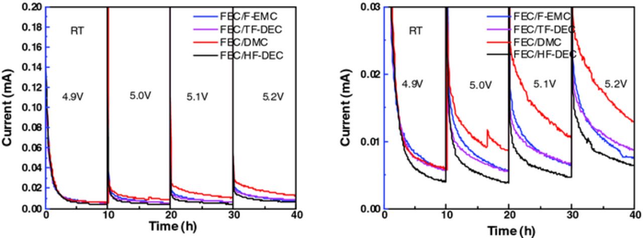
Figure 2. Floating test at RT of 0.5 M LiPF6 salt and FEC solvent mixed with DMC, F-EMC, HF-DEC, and TF-DEC at 1:1 ratio: (a) same current range as in Figure 1 and (b) low current region (below 0.03 mA).
We also investigated the effect of cyclic carbonate/linear carbonate ratio on the stability of the electrolyte. Due to poorer salt solubility of LiPF6 in the fluorinated linear carbonates, we selected DMC as the linear carbonate with FEC as the cyclic carbonate for this study. We mixed FEC and DMC at ratios of 9:1 to 1:9 in 10% increments of DMC, with 0.5 M LiPF6 concentration. Unlike the previous tests, we employed glass fiber as the separator because the formulated electrolyte does not wet the PP/PE/PP separator when the FEC content is more than 50%. To make the comparison between different FEC concentrations more straightforward, we measured the current intensity at the end of each 10 hours of holding at different potentials and plotted these current intensities against the content of FEC in the electrolyte (Figure 3). The resulting data in Figure 3 indicate that at lower potentials such as 4.9 V, the current intensities are not very sensitive to the FEC concentration. They only show a mild decline as the FEC concentration increases. This is an indication that both solvents are probably relatively stable at this potential. At higher potentials, the current intensities show much more dramatic decline over increasing FEC concentration. This finding indicates that DMC is more prone to oxidation than FEC, and its oxidation is greatly accelerated when the potential is greater than 5.1 V. Comparing the trend of current intensities at different FEC concentrations for all four potentials tested, the current intensities show that with more FEC, the electrolytes become more stable against oxidation, but the beneficial effect is not as dramatic after the concentration of cyclic carbonate is over 50%. This concludes that the cyclic carbonate FEC is more stable than the linear carbonate DMC, which again agrees with theoretical prediction. While considering the oxidation stability in formulating a new electrolyte, of course, practical concerns such as wettability of the separator and electrode also need to be considered.

Figure 3. Current intensities of floating test using solvent of FEC mixed with DMC at 1:9 to 9:1 ratio and salt of 0.5 M LiPF6. The current intensities are taken at the end of 10-hour holding at potentials of 4.9 V, 5.0 V, 5.1 V, and 5.2 V.
We also studied the effect of salt concentration on the oxidation stability of the electrolyte. In this case, we chose FEC/DMC (1:1 ratio) as the fixed solvent base and varied the LiPF6 concentration from 0.5 to 1.25 M in 0.25 M increments. The current intensities were determined in the same way as for the experiment shown in Figure 3, and the results are summarized in Figure 4. At lower potentials (4.9 and 5.0 V), the data follow the trend that the higher the salt concentration, the higher the stability of the electrolyte toward oxidation; at higher potentials (5.1 and 5.2 V) the results do not follow this pattern. It is more likely that salt concentration does not have a significant direct impact on the voltage stability of electrolyte at least in dilute electrolyte solutions, and the chosen solvent plays a dominant role. Extremely high salt concentrations may dramatically enhance the oxidation stability of the electrolyte,21 but it is beyond the scope of this study.

Figure 4. Current intensities of floating test using solvent of FEC mixed with DMC at 1:1 ratio and salt of LiPF6 with concentrations from 0.5 M to 1.25 M. The current intensities are taken at the end of each 10-hour holding at each potential.
Finally, to demonstrate the correlation of the floating test results with real cell performance, the fluorinated electrolytes from the linear carbonate group from Figure 2 were evaluated in LNMO/graphite cells. The fluorinated electrolytes from the cyclic carbonate group were not chosen because the fluorinated cyclic carbonates were responsible for the SEI formation on the graphite anode and the effectiveness of the SEI formation on the graphite anode by the cyclic carbonates may play a more important role in the overall cell performance than the anodic stability. In the linear carbonate group, all electrolyte formulations contain FEC as the cyclic carbonate which makes a fair comparison of cell performance. The cycling data of the fluorinated electrolytes were shown in Figure 5. HF-DEC based electrolyte has better capacity retention and coulombic efficiency than F-EMC and TF-DEC based electrolytes (Figure 5b). The cell performance is consistent with the floating test results as discussed above.

Figure 5. (a) Galvanostatic cycling performance and (b) capacity retention of LNMO/graphite cells at room temperature using electrolyte formulated with 1.0 M LiPF6, FEC mixed with F-EMC, HF-DEC or TF-DEC at 1:1 ratio.
Conclusions
Electrochemical floating tests have been used as an evaluation tool for the voltage stability of electrolyte solvents. Of the cyclic carbonates screened, FEC is the most stable solvent, followed by TFPC, EC, and TFP-PC-E. The differences of voltage stability are much more pronounced at elevated temperature than at RT. Although FEC is the most stable among the cyclic carbonates tested, practical concerns should also be taken into consideration for selection of the solvent such as thermal stability, chemical reactivity and gassing issue. For the linear carbonates, HF-DEC is the most stable, followed by F-EMC, TF-DEC and DMC. Mixtures of FEC and DMC in various ratios demonstrated that FEC is the more stable component in the binary formulations of FEC/DMC, although the beneficial effect is insignificant after the concentration of cyclic carbonate is increased over 50%, and wetting issue begins to arise. Testing of various salt concentrations did not result in great variation of the electrolyte stability, implying that the effect of the salt on the electrolyte voltage stability is minimal in dilute electrolytes. Lastly, results from the floating tests were validated in LNMO/graphite coin cell cycling tests in agreements.
Acknowledgments
This research is supported by the U.S. Department of Energy, Vehicle Technologies Office. Argonne National Laboratory is operated for the U.S. Department of Energy by UChicago Argonne, LLC, under contract DE-AC02-06CH11357. We thank the Cell Analysis, Modeling, and Prototyping (CAMP) Facility of Argonne's Chemical Sciences and Engineering Division for providing the electrode materials. The submitted manuscript has been created by UChicago Argonne, LLC, Operator of Argonne National Laboratory ("Argonne"). Argonne, a U.S. Department of Energy Office of Science laboratory, is operated under Contract No. DE-AC02-06CH11357. The U.S. Government retains for itself, and others acting on its behalf, a paid-up nonexclusive, irrevocable worldwide license in said article to reproduce, prepare derivative works, distribute copies to the public, and perform publicly and display publicly, by or on behalf of the Government.