Abstract
A technique has been developed to allow for in-situ observation of the state of the liquid electrolyte present in an electrochemical device through exploiting the nature of solid-liquid phase transitions. An apparatus was developed to perform differential thermal analysis (DTA) on complete NMC/graphite lithium-ion pouch cells. The DTA apparatus monitored the temperature of a sample cell alongside that of a thermally inert reference cell during a controlled temperature scan through the melting point of the electrolyte in the sample cell, producing a thermal signature of the sample electrolyte without damage to the cell performance. This signature holds information pertaining to the composition and amount of liquid electrolyte present in the electrochemical device, allowing for detailed study of electrolyte evolution at various points of life and indications of the state-of-health of the device.
Export citation and abstract BibTeX RIS

This is an open access article distributed under the terms of the Creative Commons Attribution 4.0 License (CC BY, http://creativecommons.org/licenses/by/4.0/), which permits unrestricted reuse of the work in any medium, provided the original work is properly cited.
In recent years, lithium-ion batteries have surpassed other competing technologies as the pre-eminent choice in a wide range of energy storage applications. With expansion beyond use in personal electronics into mainstream automotive applications and grid storage, a more complete understanding of the complex processes evolving in these devices over a decade of life is of utmost importance. A generic lithium-ion cell comprises two electrodes and a liquid electrolyte (itself composed of ever-increasingly complex systems of lithium-based salts, organic solvents and a blend of electrolyte additives intended to stabilize and improve the cell operation and lifetime). Parasitic reactions are known to coincide with regular operation of the device, leading to reduction and oxidation of the liquid electrolyte through development of solid electrolyte interface layers (SEI) and also other reactions at the electrodes.1–3 Depending on the specific electrolyte chemistry and cycling protocol, this may result in substantial changes to the chemistry of the electrolyte compared to that introduced to the cell at time of manufacturing, significant electrolyte consumption, or both.
To date, studies of this evolution have been limited to ex situ post mortem studies of the cells. Possible methods include X-ray photoelectron spectroscopy (XPS)2 and gas chromatography coupled with mass-spectrometry (GC/MS).4 These studies are limited as XPS studies the SEI directly as opposed to the electrolyte itself and GC/MS is insensitive to the electrolyte salt. Furthermore, all such schemes are inherently destructive, precluding intermittent study of a single cell at arbitrary points of life.
A thorough understanding of the evolution and loss of liquid electrolyte are critical to both determining chemistries for study in research programs, as well as establishing the value and remaining lifetime of an used lithium-ion cell. The strict capacity requirements for Li-ion cells in electric vehicles necessitating battery disposal at an intermediate state of life has resulted in the recent emergence of a used-battery market.5,6 This further underscores the value of a robust state-of-health technology. As such, the desire for an in situ probe, allowing for non-destructive observation of the composition and amount of liquid electrolyte remaining in an aged Li-ion cell is of paramount importance.
We report here the development of one such probe, conceived on the basis of differential thermal analysis (DTA).7–9 Related closely to the more familiar method of differential scanning calorimetry (DSC), DTA relies on the fundamental properties of liquid-solid phase transitions, to extract information about the mass, enthalpy of fusion and phase diagram of a sample. Due to the associated enthalpy of fusion, the temperature of a solid sample will plateau in time during heating as it reaches the phase transition temperature. The duration of this plateau is directly correlated to the amount of solid being melted. While measuring the temperature of a sample alongside a thermally inert reference through a linear temperature ramp, a thermal lag between the two samples will develop during the phase transition. The difference in temperature between sample and reference (Tsample − Treference) thus constitutes the DTA signal.7–9 During a melting event, this difference can be represented graphically in the form of a peak when plotted against reference temperature or equivalently, time. By a thermally inert reference, the absence of phase transitions over the temperature range of interest is implied.
In principle DTA can be done for both melting and freezing, but emphasis here is placed on the former due to its independence of crystallization kinetics. The DTA peak thus contains information regarding the transition temperatures and with an understanding of enthalpy of fusion, the mass of the liquid electrolyte as well. As the liquid electrolytes involved are complex ternary or often higher order solutions of salts, organic carbonates and other chemicals, a typical DTA signal has multiple features composing a unique thermal fingerprint of the electrolyte of interest. As examples, Ding et al.10,11 have characterized some binary Li-ion battery solvent systems using DSC which allow the phase diagram of the binary solvent mixture to be determined. However, inclusion of salt to determine phase diagrams of the full ternary systems relevant to Li-ion devices has yet to be reported in the literature. Such characterization would allow for a quantitative evaluation of the electrolyte composition at various states of life. Nevertheless, by tracking the evolution of the DTA fingerprint over the lifetime of a cell, the composition of liquid electrolyte can be found to vary substantially, and the potential of this technique to elucidate this variation in a non-destructive fashion is illustrated.
In this paper the Li-ion DTA technique is introduced and its ability to measure cells repeatedly and non-destructively is demonstrated. The ability to determine consumption of a specific electrolyte component is then presented. This is done by offering evidence of salt consumption in an aggressively cycled lithium-ion pouch cell via DTA alongside complimentary GC/MS, illustrating that relative solvent ratios do not change significantly, in corroboration with the conclusions from the DTA studies. The impedance spectra of Li-ion cells changes as they age. Careful interpretation of the spectra can give information about changes to the interfaces between the electrode particles and the electrolyte, the integrity of the conducting diluent, the integrity of the ionic path within the electrodes and the electrode/current collector interfaces. The Li-ion DTA technique gives information about the amount of liquid electrolyte remaining in the cell and about the electrolyte composition, as we demonstrate here, which impedance spectroscopy does not.
Experimental
Figure 1 shows a schematic diagram of the cryostat apparatus developed. Two cells are suspended in a small aluminum can from a polypropylene support. The cells are pressed against 100 Ω Platinum RTDs embedded in the support that convey temperature readings to the control computer. The temperature program itself is controlled via an identical RTD mounted against the inner wall of the cryostat can. Cooling power is provided via contact between the outer base of the cryostat can and a copper post resting in a dewar of liquid nitrogen (LN2). The control computer then operates in tandem with a Lakeshore 340 temperature controller to provide the heating power to a 30 W resistive tape (Electroflex) wrapped around the outside of the cryostat can. This system allows for a linear temperature ramp to freeze the liquid electrolyte followed by an equilibrating soak period and subsequent temperature ramp back to room temperature. During the cooling cycle, direct contact is made between the copper post and the cryostat can. This contact is broken during the hold period, effectively decoupling the cryostat from the cold reservoir. The gap is maintained during the heating ramp, allowing the small 30 W heater tape to provide a smooth linear temperature ramp.
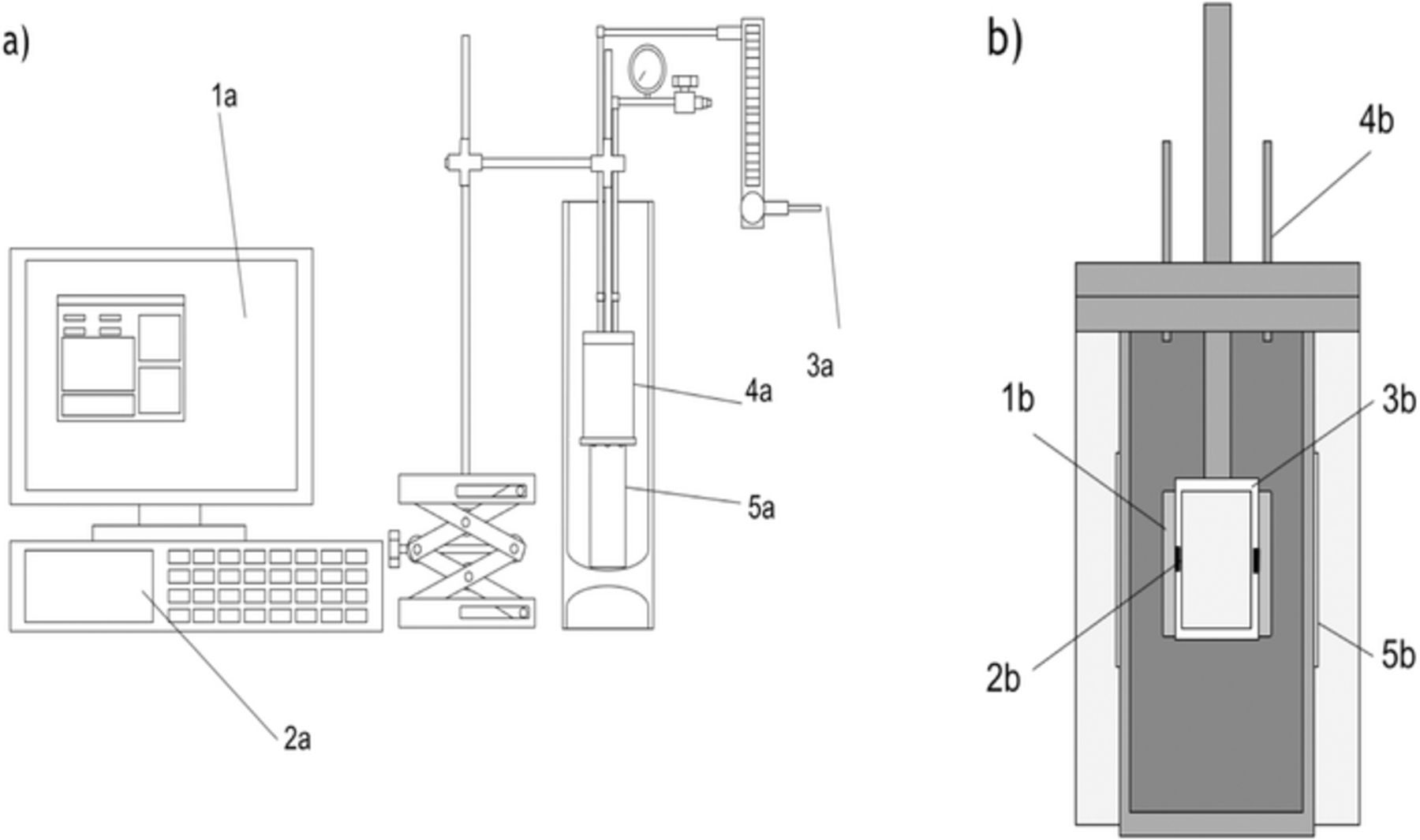
Figure 1. (a) Apparatus diagram. Control computer (1) programs Lakeshore 340 Temperature Controller (2) and collects temperature data from the device. (3) Helium flows through cryostat (4) to provide thermal contact with cells. Cryostat is coupled to cold reservoir via copper post submerged in LN2 (5). (b) Cross section of cryostat (4a). Pouch cells (1) mounted against RTD (2), embedded in plastic mount (3), suspended in cryostat. The sample and reference cells are mounted opposite one another. Helium (4) flows through lid of cryostat. Heater tape (5) wraps around cryostat, below insulating alumina wool.
For the LiPF6:EC:EMC systems considered here, the crystallization event is complete by −90°C and the onset of the solidus line in melting begins between −90°C and −80°C so a lower bound of −105°C was used. This accommodates the effects of thermal inertia at the beginning of a temperature ramp, allowing the system to reach a state of linearity before onset of thermal events. All data presented here was collected with a cooling rate of −2.5°C/min and a heating rate of 2.0°C/min. The two segments were separated by a 10 minute soak at the lower temperature setpoint to allow for thermalization of the system. A small flow of 85 ± 5 mL/min of He gas was maintained at an overpressure of 40 kPa throughout the experimental run to avoid fictitious crystallization and melting events near 0°C associated with water vapor, in addition to improving thermal homogeneity and contact within the cryostat. Consistency in the heating rate parameter is of utmost importance when comparing data sets in DTA. While a higher heating rate allows for a larger peak, it comes at the expense of sensitivity to features. It is important to emphasize that comparison of data with different rates is not as trivial as a simple scaling of data sets. This is most apparent in situations where the melt feature is not a straightforward eutectic, and consecutive events follow one another closely in temperature. With a choice of 2.0°C/min, most features can be well distinguished with exceptional signal-to-noise. Furthermore, data collection occurs on a practical time scale, allowing for a full experimental trial to be completed in approximately 2.0 hours. More complex apparatus designs allowing for simultaneous measurement of multiple cells are being developed to facilitate more efficient data collection.
The apparatus pictured was designed for use with 402035 pouch cells. These are provided dry (no electrolyte) from Li-Fun Technology (Xinma Industry Zone, Golden Dragon Road, Tianyuan District, Zhuzhou City, Hunan Province, PRC, 412000, China) and as suggested by the classification, measure 40 mm × 20 mm × 3.5 mm. In principle, analogous apparatus can be designed and constructed for arbitrary cell geometries, provided the cells themselves are of reasonably small size to allow for effective thermal conduction and homogeneity through the sample. An apparatus designed for 18650 cells has been constructed and experiments on those cells will begin shortly. While the work presented here uses a human machined polypropylene support to hold the cells and their sensors, 3D printed ABS-based supports for more intricate cell geometries have also been used.
The cells used in this study are composed of electrodes wound in a spiral orientation. A 20 μm thick polypropylene separator coated with Al2O3 on the positive electrode side, was used in these cells. The positive electrode measured 200 mm × 26 mm and the negative electrode 204 mm × 28 mm. In all cases, the negative electrode material was graphite, whereas the positive electrodes were all LiNixMnyCozO2-based. Specifically, this study employed LiNi0.33Mn0.33Co0.33O2 (NMC111) and LiNi0.4Mn0.4Co0.2O2 (NMC442) positive electrodes. NMC111 cathodes were composed of active material:carbon black:PVDF binder = 96.2:1.8:2.0 and graphite anodes were active material:carbon black:CMC:SBR = 95.4:1.3:1.1:2.2. The cathode coating had a thickness of 105 μm and was pressed via calender to a volumetric density of 3.55 g/cm3 and an areal density of 16 mg/cm2. The negative electrode coating had a thickness of 110 μm and was similarly pressed to a volumetric density of 1.55 g/cm3 and areal density of 9.5 mg/cm2. NMC442 cells used were of a comparable construction to these specifications.
The reference cell used throughout was identical in pouch construction to that of the sample, with the possible exception of the positive electrode NMC ratio. The electrolyte used in the reference cell was 1.0 M LiPF6 in methyl acetate (MA) (BASF), selected for its low freezing point; crystallization of this solution does not occur above −115°C in these pouch cells. The use of a reference cell for calculation of temperature differentials is imperative. Substitution of the reference cell temperature with the cryostat temperature was vastly inferior, as the cryostat was more susceptible to thermal fluctuations and did not follow the temperature profile of the sample cell as closely.
In order to validate the results from the Li-ion DTA system, DSC measurements of electrolyte samples were made using a TA-instruments Q-1000 DSC equipped with a refrigerated cooling system and a 49 sample automatic sample loader. Hermetic aluminum pans from DSC Consumables were prepared with a stack of electrode and separator material taken from a LiFun NMC/graphite pouch cell. This was done to mimic the conditions in the pouch cell and to minimize supercooling.12 A drop of electrolyte was deposited onto the stack before sealing the pan. All preparation of DSC samples was done in an argon-filled glove box.
Results and Discussion
1.0 M LiPF6 in EC:EMC (3:7 wt%) (BASF, < 20 ppm water) was chosen as the base, or control, electrolyte in these studies. This decision was not motivated by facility, and as suggested in the Experimental section, this chemistry does not fully crystallize above −90°C. Furthermore, the DTA melt signature is complex in nature. Before the formation step of the pouch cells, i.e. just after filling and vacuum sealing, this electrolyte displays three distinct features in the DTA experiment, shown clearly in Figure 2. By contrast, the mixed EC:EMC solvent system (No LiPF6) does not show the lowest temperature feature.10 The lowest temperature feature corresponds to the melting of a low temperature salt-solvent complex which is then followed closely by the second feature which is an EMC-dominated solidus feature. At higher temperatures, a broad onset EC-based liquidus feature is observed. The two higher temperature features match those reported by Ding et al.10 but with a significant melting point depression due to the LiPF6 salt.
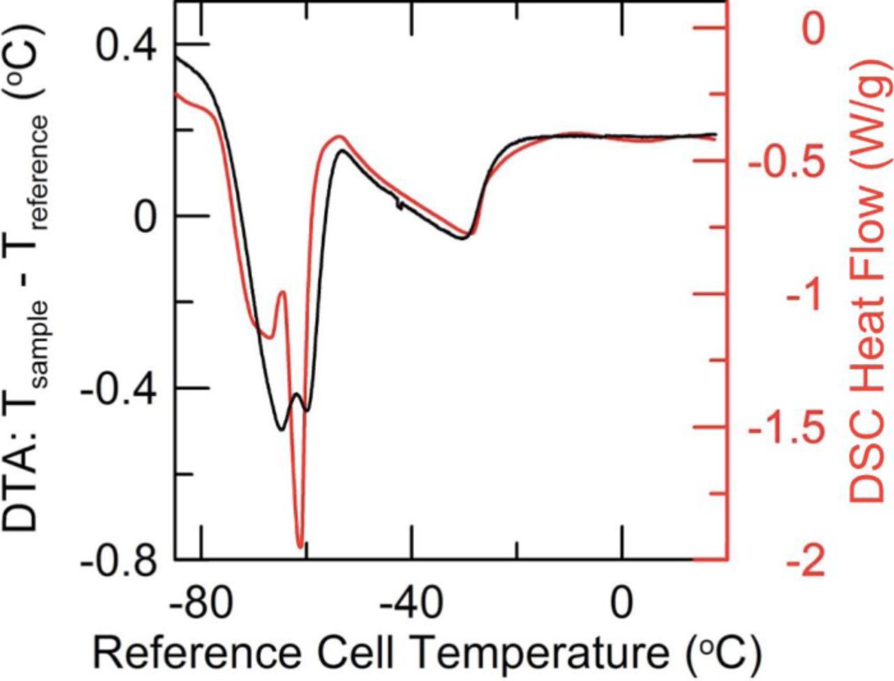
Figure 2. DTA (black) and analogous DSC (red) trace for 1.0 M LiPF6 in EC:EMC (3:7 wt%) in an NMC/graphite-based environment. The DTA curve was collected using full pouch cells, in contrast to the DSC trace, where a small cylindrical stack of electrodes and separator were placed in an hermetic aluminum pan with electrolyte. No background subtraction has been done on either data set.
Figure 2 also shows a DSC trace collected on the same electrolyte. Both DSC and DTA experiments confirm the existence of the lowest temperature feature due the salt-solvents complex. The existence of this feature has been confirmed for a number of salt concentrations at this EC:EMC ratio via DSC. In addition, the solidus and liquidus features as measured in Li-ion cell DTA and electrolyte DSC match very well. It is thus important to emphasize here the vast disparity in sample size. While a DSC pan holds 4 mg of electrolyte in a 65 mg cell (pan and lid with electrode), the Li-ion DTA apparatus measures the signal from 0.9 g of electrolyte in a 4.5 g pouch cell. Despite this incongruity, the ability of a "home made" DTA apparatus to produce data of comparable fidelity to a commercial DSC, in a sample orders of magnitude larger in size is suggestive of the capacity of the DTA method to detail the thermochemical properties of full Li-ion cells. At the same time, the relative ease and speed with which a full array of DSC samples may be prepared, covering the full phase space of the LiPF6:EC:EMC electrolyte system is suggestive of the ability to render DTA more quantitative. With a full understanding of the enthalpies of fusion associated with the various solidus and liquidus features of this system, the DTA peak areas can be linked quantitatively to the amount of each electrolyte component in the cell. This is the focus of ongoing work, as at this time the technique is limited to qualitative discussions of the electrolyte composition. Unless otherwise specified, the baseline of all DTA data presented here has been subjected to a cubic-spline background subtraction. No other data processing or smoothing has been done to these curves.
Before committing valuable aged cells to this novel scheme, it was important to establish the non-destructive nature of this method. As such, a group of dry 230 mAh LiNi0.33Mn0.33Co0.33O2/graphite (NMC111/graphite) pouch cells were prepared with 0.9 g of 1.0 M LiPF6 in EC:EMC (3:7 wt%) with 2% VC and cycled at C/5 and 40°C. Of the five cells prepared, one was measured with the DTA immediately following formation to 4.2 V. Two cells were periodically measured with the DTA a total of five times, and two others were simply left on the charger without being exposed to DTA. As displayed in Figure 3c, the cycling data for all five cells shows little differentiation. Over 160 cycles, there is no indication that the spread in capacities observed initially has changed. The data shows two points at which all capacities are observed to jump. This was a result of a prolonged pause in the cycling protocol and affected all cells similarly.
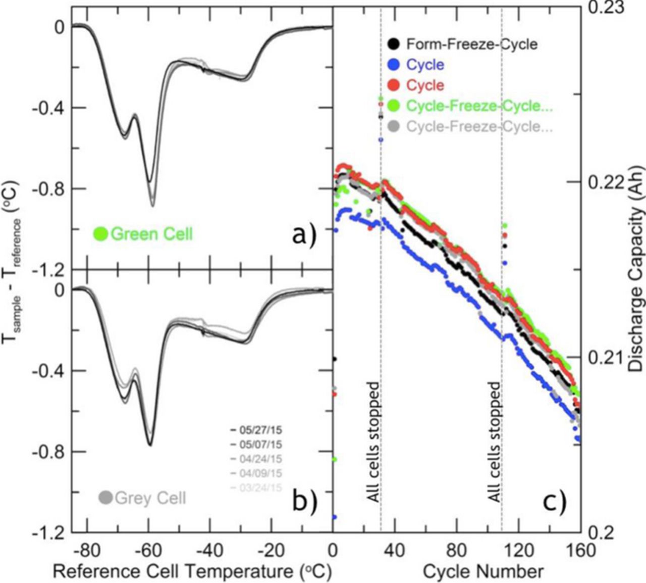
Figure 3. (a),(b): Repeated DTA measurements of 1.0 M LiPF6 in EC:EMC (3:7 wt%) with 2% VC during cycling. Cells are size 402035 NMC111/graphite from LiFun. Date of measurement is indicated in the legend of 3b. Over this period, little differentiation in the signal occurs. Earlier curves display a kink in data near −40°C. This results from use of unsuitable thermal compound for contact between cells and RTD which froze and melted near this temperature. Later trials display more smooth behavior in this region due to substitution with Apezion N, a cryogenic grease more appropriate for this application. (c): Discharge capacity data for the cells measured on DTA in 3a and 3b, alongside their pair cells which were exposed to DTA either once or not at all. Cells were cycled at C/5 between 2.8 V and 4.2 V at 40°C.
In the left hand panel of Figure 3, repeated DTA measurements are presented for the gray and green cells in Figure 3c, emphasizing the repeatability of this procedure. In agreement with the small 5–10% change in overall capacity during this cycling regime, the DTA curves display no substantive change in either peak depths, or onset temperatures. Together this implies a conservation of both electrolyte salt and solvent over the course of study.
To further illustrate the capacity of this tool to provide valuable information, we present evidence for the well-known phenomena of trans-esterification in EC:EMC blends.13,14 In the absence of stabilizing additives, about 50% of the EMC is converted to DEC and DMC during formation.4 DEC has a very low freezing point and work by Ding et al.10,11 shows that some solvent mixtures with DEC do not freeze even to −90°C before addition of salt. As such, under the experimental procedure detailed above, much of the liquid electrolyte will not crystallize, and is absent from the melt profile. Figure 4 shows DTA measurements for NMC/graphite pouch cells with control electrolyte before and after formation as well as for control electrolyte containing 2% VC after formation. The stark contrast between the pre-formation control cell or post-formation 2% VC cell when compared against the post-formation control cell is clearly apparent. Although largely preserved, the DTA feature of a cell with 2% VC is markedly different from the pre-formation control cell, emphasizing the impact of additives, and consequently the importance of establishing a suitable reference curve for the particular electrolyte chemistry. Eom et al.14 and Petibon et al.4 report only trace amounts of VC remaining after formation, suggesting near total consumption in the SEI. The differences between pre-formation control and the VC cell can be attributed largely to reactions happening during the formation process and small variations in salt concentration between the different cells. In order to track the evolution of cell chemistry with DTA, a fresh cell should be measured with DTA so as to establish a baseline from which to compare the aged cell.
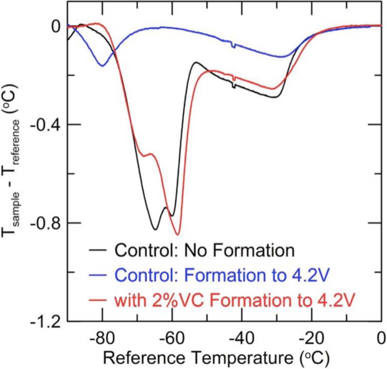
Figure 4. DTA curves for three different cells with similar electrolyte. The black curve shows control (1.0 M LiPF6 in EC:EMC (3:7 wt%)) before formation. After formation to 4.2 V and following transesterification of some of the EMC into DEC and DMC, the thermal signature is dramatically reduced. This is displayed in the blue curve. The red curve represents a cell with the same electrolyte, but with an additional 2% VC wt% where transesterification does not occur during formation.
The DTA technique can be applied to track and understand the evolution of the electrolyte after long periods of cycling, in order to diagnose the cause of cell breakdown and failure. Figure 5 shows the capacity versus cycle number for a LiNi0.4Mn0.4Co0.2O2/graphite (NMC442/graphite) pouch cell filled with 1.0 M LiPF6 in EC:EMC (3:7 wt%) and "PD211" additive blend (2% prop-1-ene sultone (PES) + 1% 1,3,2-Dioxathiane 2,2-dioxide (DTD) + 1% tris(trimethylsilyl) phosphite (TTSPi)). This additive blend has been observed to improve coulombic efficiency, reduce impedance during high potential cycling and lower gas evolution in NMC/graphite pouch cells.15,16 The cells were initially cycled for 16 times between 2.8 V and 4.4 V at C/10 and 40°C with a 10 hour storage period at the top of each charge. They were later switched to a more aggressive protocol of cycling between 2.8 V and 4.5 V at C/2.5 and 40°C for 500 cycles. Figure 5b displays the resulting substantive loss of capacity during the second set of cycles. At this point, the cell was measured with DTA, and compared to a fresh cell filled with the same electrolyte and formed. Figure 5a shows the DTA curves for the fresh cell and the cycled cell. There are dramatic differences in the curves which will now be considered.
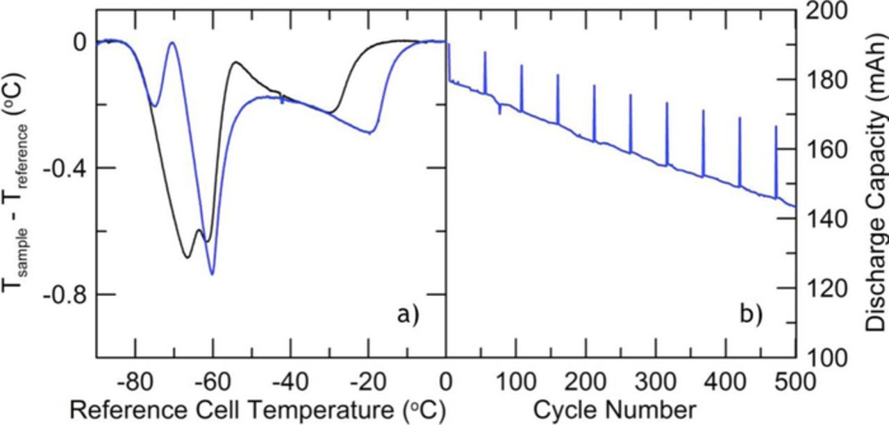
Figure 5. DTA curves for 1.0 M LiPF6 in EC:EMC (3:7 wt%) with PD211 before (black) and after (blue) cycling. (a) Discharge capacity data during cycling for the cell detailed in blue in 5a.
Figure 3 in the paper by Ding et al.10 shows the phase diagram of the EC:EMC solvent blend. The liquidus curve moves strongly to higher temperature as the EMC content is reduced. There are some data in Figure 3 of Ding et al.10 that show that the liquidus temperature is dramatically reduced as the LiPF6 content increases at EC:EMC = 1:1 mole ratio. (3:7 wt% corresponds approximately to 1:2 mole ratio EC:EMC). The solidus temperature is affected less dramatically with a change in the LiPF6 content. Thus, the changes in the liquidus feature (the highest temperature feature in Figure 5a) might be explained by either a reduction in salt content or an increase in the EC:EMC ratio.
To explore the viability of these hypotheses, Figure 6 shows the Li-ion DTA signals for fresh cells (both before and after formation) prepared with PD211 in EC:EMC (3:7 wt%) and varying concentrations of salt: 0.6 M, 0.8 M, and 1.0 M LiPF6. The features in Figure 5a for the cycled cell match those of the 0.8 M LiPF6 data in Figure 6 quite well, suggesting a consumption of LiPF6 salt during the aggressive cycling in Figure 5b.
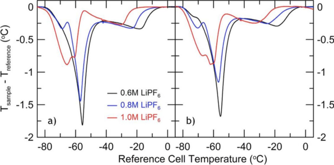
Figure 6. DTA curves for different concentrations of LiPF6 in EC:EMC (3:7 wt%) with PD211 before (6a) and after (6b) formation.
In order to confirm that these conclusions regarding the cell in Figure 5b are not misguided through convolution with effects of solvent evolution, e.g. EC:EMC ratio, GC/MS data was also collected on the electrolyte recovered from this cell. This followed the procedure outlined by Petibon et al.,4 and, as such, is insensitive to salt concentration. The GC/MS results indicate that the solvent was composed of 36.4% EC, 63.3% EMC and 0.3% DEC by weight. This suggests a small overall loss of the EMC component, having begun with EC:EMC:DEC = 30:70:0. According to the EC:EMC phase diagram of Ding et al.,10 this composition change could shift the liquidus temperature by at most about 3°C, much less than that observed in Figure 5a. Therefore, it can be stated confidently that the cycling procedure in Figure 5b has led to the consumption of about 0.2 M of LiPF6.
Through improved characterization of the phase diagram and the associated enthalpies of fusion for electrolyte systems of interest, a more quantitative understanding of the salt or solvent consumption through integration of the DTA signal can be gained. The purpose of this paper has been to introduce the Li-ion DTA method and to demonstrate the power of the method. It may be worth pointing out that this method, in principle, can be used to study the state-of-health of any electrochemical device with a liquid electrolyte.17
Conclusions
The viability of DTA on a full Li-ion cell as a non-invasive in situ method for characterization of the state of the liquid electrolyte in a Li-ion cell has been demonstrated. The thermal lag accumulated during a melting event of the electrolyte produces a repeatable and unique signature of the electrolyte without incurring damage to the cell.
In principle, this technique should allow for both qualitative and quantitative characterization of electrolyte evolution, indicative of the state of the health of the Li-ion cell. Changes in the DTA signal expected in canonical reactions in Li-ion cells have been observed, as well as those of significant salt consumption during aggressive cycling regimes. We are working toward application of this method to even more industrially pertinent cell geometries (such as 18650-size cells), as well as completing full DSC characterization of the related phase diagrams of relevant systems so as to improve the quantitative capacity of this tool.
Acknowledgments
The authors thank NSERC and 3 M Canada for funding this work under the auspices of the Industrial Research Chairs program. In addition, the authors thank Dr. Jing Li of BASF for providing the solvents, salts and some of the additives used in this work. Remi Petibon thanks NSERC and the Walter C. Sumner Foundation for scholarship support.