Abstract
In this study, the synthesis of ammonia (NH3) at ambient pressure using H2 and N2 is electrochemically achieved. The conducting and reaction media with molten salt consist of molten hydroxide as NaOH and KOH whereas the reaction temperature is varied in the range of 200°C to 255°C to investigate the impact of temperature on the ammonia production rate and hence performance. The porous nickel mesh electrodes having an area of 100 cm2 are used as cathode and anode where the supplied electricity is controlled using potentiostat/galvanostat. The maximum faradaic efficiency for ammonia synthesis is found to be 9.3% at 210°C corresponding to 6.53 × 10⁻¹⁰ mol/s cm2 ammonia evolution rate at 2 mA/cm2 current density with nano-Fe3O4 as the catalyst. Furthermore, the applied voltages and applied currents are varied to find the optimum experimental conditions for molten salt electrolyte based electrochemical ammonia synthesis.
Export citation and abstract BibTeX RIS

This is an open access article distributed under the terms of the Creative Commons Attribution Non-Commercial No Derivatives 4.0 License (CC BY-NC-ND, http://creativecommons.org/licenses/by-nc-nd/4.0/), which permits non-commercial reuse, distribution, and reproduction in any medium, provided the original work is not changed in any way and is properly cited. For permission for commercial reuse, please email: oa@electrochem.org.
Ammonia is expected to serve as a potential hydrogen carrier with high hydrogen content in the near future. In recent years, expectations have even further increased for hydrogen and hydrogen carriers as a medium for storage and transportation of energy in the mass introduction and use of renewable energy. Both storage and transport of hydrogen are considered an important issue since hydrogen is in gas form under normal temperature and pressure. Hydrogen carriers are mediums that convert hydrogen into chemical substances containing large amounts of hydrogen, to simplify storage and transport processes. Hydrogen carriers include ammonia synthesized from nitrogen and hydrogen that can be used for direct combustion, fuel cells, cooling, fertilizer, etc. Ammonia becomes an important hydrogen carrier due to the fact that it does not contain any carbon atoms and has a high hydrogen ratio. Therefore, it is evaluated as a clean power-generating fuel. Since ammonia produces mainly water and nitrogen on combustion, replacing a part of conventional fuel with ammonia will have a large effect in reducing carbon dioxide emissions. A most common ammonia synthesis technique is recognized as Haber-Bosch process in the world. Natural gas is the primary feedstock used for producing ammonia in worldwide which increases the fossil fuel dependence and greenhouse gas emissions. Therefore, alternative ammonia synthesis methods are in development stage such as electrochemical ammonia synthesis which can be integrated to solar energy applications for producing green ammonia.1
The electrochemical process can be carried out under ambient conditions or at higher temperatures depending on the type of the electrolyte material used. For high temperature electrolytic routes of ammonia production, the use of waste heat from thermal or nuclear power plants or heat from renewable energy sources like solar would make the overall process more environmentally friendly. Ammonia production from hydrogen and nitrogen is exothermic in nature and is facilitated by high pressures and low temperatures. Thus a balance between the operating temperature, pressure and the ammonia yield needs to be proven for electrochemical system in determining ammonia production rates. Among solid state electrolyte methods, there are studies available in the literature although maximum production rates are lower than molten salt electrolyte based methods. A study used a proton-conducting solid electrolyte at 450°C to 700°C with Ru based catalyst. They resulted that the conversion rates are lower compared to nitrogen or steam because of the low conductivity of the working electrode.2 In another study with a Nafion divider in aqueous 2 M KOH and a Ru on cathode, ammonia generation from water and nitrogen at a rate of 2.8 × 10⁻¹² mol NH3/s cm2 and coulombic efficiency of 0.9% at 20°C was achieved. Also, at 90°C, a maximum rate of 2.1 × 10⁻¹¹ mol /s cm2 at 0.2% efficiency was observed.3 Membrane based applications can be performed at quite lower temperatures than molten salt electrolyte based methods. Having Pt/C on a gas diffusion layer at both electrodes and room temperature, using Nafion as the electrolyte yielded NH3 at a higher rate corresponding to 1.1 × 10⁻⁹ mol/s cm2, which consumed water at the anode and air at the cathode with 0.6% coulombic efficiency.4 In addition, there is also a molten NaOH-KOH eutectic electrolyte based ammonia fuel cell studied by researchers which also confirm that molten salts can be used in the fuel cell applications.5 Licht et al.6 obtained about 35% faradaic efficiency where they supplied water and air to produce ammonia in molten salt electrolyte. In their further research Li and Licht7 reported that since they used water as hydrogen source, at 200 mA/cm2, over 90% of applied current generated H2, rather than NH3. In this case, hydrogen was cogenerated but required higher potentials because of essential water splitting voltage.
Numerous electrochemical methods have recently been developed for consideration as alternative syntheses of NH3.8–13 Furthermore, various production and utilization options of ammonia have been discussed in many studies.14–16 Kugler et al.17 studied to increase the NH3 generation rate by applying galvanic deposition of Rh and Ru on Ti felts in which they observed higher formation rates for Rh coatings. Kim et al.18 performed electrochemical synthesis of ammonia in molten LiCl-KCl-CsCl electrolyte by a mixture of catalysts as nano-Fe2O3 and CoFe2O4. Their maximum formation rate was 3 × 10⁻¹⁰ mol/s cm2 where they used water and nitrogen for the reaction.
Xu et al.19 investigated generation of ammonia at atmospheric pressure and low temperature electrochemically, using the SFCN materials as the cathode, a Nafion membrane as the electrolyte, nickel-doped SDC (Ni-SDC) as the anode and silver-platinum paste as the current collector. NH3 was produced from 25°C to 100°C temperature levels when the SFCN materials were utilized as cathode, with SmFe0.7Cu0.1Ni0.2O3 which gives the maximum rates of ammonia formation. Garagounis et al.20 summarized the test results of studies within the last 15 years using electrolyte cells. More than 30 electrolyte materials with 15 catalysts that were used as working electrodes (cathode) were tested. Nafion can be used as a proton conductor with and a Ru/C cathode which yielded NH3 from H2O and N2 at 90°C. These low operating temperatures are sought after when designing new systems because of the reduced energy input and lower rate of decomposition of the ammonia formed. As an alternative approach, the use of oxygen ion conductors where steam and nitrogen are introduced together at the cathode can be considered. The rate of NH3 production was however very small in a demonstration at 500°C but improved by up to two orders of magnitude at higher temperatures as reported by Skodra et al.21 Furthermore, NH3 synthesis using molten salt electrolyte based systems can yield high conversion ratios similar to that of polymer based membranes. Solid-state proton conductors (SSPC) denote a class of ionic solid electrolytes which have the capability to transfer hydrogen ions (H+).22 However, this method has some disadvantages such as high temperature requirement and formation of secondary phases.23–25 A variety of factors need to be analyzed when selecting the cell material such as system operating temperature, current density, pressure, and conductivity which affect the ammonia production rate. It is important to note that conductivity of a solid electrolyte increases exponentially with temperature and by reducing cell thickness as reported by Giddey et al.26 Kyriakou et al.27 recently reported extensive literature data about low temperature, medium temperature and high temperature electrochemical NH3 synthesis routes showing that the synthesis rates can reach up to 3.3 × 10⁻⁸ mol/s cm2. Shipman and Symes28 presented the recent developments in electrochemical NH3 production and they categorized the sources of proton as water, hydrogen and sacrificial proton donors. They resulted that the techniques keeping the temperatures in the range of 100°C and 300°C may well demonstrate to be the most efficient.
Although synthesis of NH3 using water as hydrogen source in electrochemical process is attractive and reduces additional step, for the cases where ammonia and hydrogen are individually required as alternative fuels, H2 can be directly utilized in the electrochemical NH3 formation as investigated in this study. Most of the literature used water as hydrogen source which also requires water splitting process at the same time with ammonia synthesis. Specifically, for solar energy storage applications, H2 can act as short-term storage whereas NH3 can serve as long-term storage medium which reduces the storage losses significantly. In this study, we report electrochemical synthesis of ammonia using H2 and N2 at ambient pressure in a molten hydroxide electrolyte with nano-Fe3O4 catalyst. The active surface areas of the Nickel mesh electrodes are increased to allow higher formation rates. The effects of various parameters such as applied potential and current density, reaction temperature on ammonia formation rate are investigated. The nickel mesh electrodes are utilized having large surface area of 100 cm2 and the reaction temperatures are quite lower than the conventional Haber-Bosch process.
Experimental Investigation and Analysis
In this study, H2 and N2 are directly used for electrochemical synthesis of ammonia at the electrodes. N2 receives the electrons from external power supply. Hence nitrogen gas sent via the porous nickel cathode is reduced to nitride according to the following equation:
![Equation ([1])](https://content.cld.iop.org/journals/1945-7111/164/8/H5036/revision1/d0001.gif)
It becomes N3− then after moves to the other electrode where H2 is being supplied. Hydrogen ions combine with nitrogen ions and form NH3 at anode electrode as illustrated in Fig. 1 and shown the following equation:
![Equation ([2])](https://content.cld.iop.org/journals/1945-7111/164/8/H5036/revision1/d0002.gif)
The anode reaction is also achieved on porous nickel electrode.
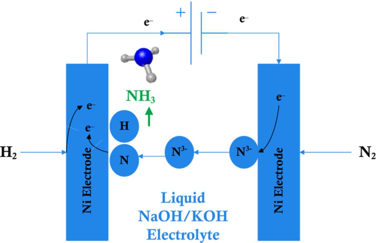
Figure 1. Electrochemical ammonia synthesis reaction in molten salt medium.
The overall reaction is:
![Equation ([3])](https://content.cld.iop.org/journals/1945-7111/164/8/H5036/revision1/d0003.gif)
Hydrogen and nitrogen are required separately to be produced and supplied to the ammonia synthesis reactor. To conduct the electrochemical reaction for ammonia synthesis, reactant nitrogen is supplied from then nitrogen tank. For the production of hydrogen, a separate electrode-electrolyte assembly was formed consisting of graphite rods and NaOH electrolyte. The volume of the electrolyte is 1 L whereas the molarity of NaOH solution is 1 M.
Nickel mesh is used for both electrodes each having an area of 100 cm2 as shown in Fig. 2. Nickel meshes have high melting point, non-corrosivity, high conductivity and good stability in molten salt medium. The area of 100 cm2 is used for faradaic efficiency calculations. The reactor, 500 mL crucible, is made of Alumina (Al2O3) being 99.6% pure, having high melting point, strong hardness, chemical stability and non-corrosivity. The cover plates are made of stainless steel (316 alloy) which withstand high temperatures.

Figure 2. Reactor design showing the nickel mesh electrodes, reactants & products tubing for the reactor.
The molten salt electrolyte is a mixture of 0.5 M NaOH and 0.5 M KOH. The mass of the NaOH is 221 g whereas KOH mass is 310 g. The total volume of the mixture is about 430 mL at 200°C. The mixture is originally prepared at room temperature, putting the salts into the reactor to melt in the crucible when heated up to 255°C.
Iron oxide (Fe3O4) as nano-powder (20–30 nm, 98+%) is used in the experiments as catalyst. The high surface area of the nano-Fe3O4 in the electrochemical synthesis is critical for the reaction to occur and to obtain higher ammonia evolution rates. Since ammonia is highly soluble in water, the molten salt electrolyte is not mixed with the water inside the reactor to allow higher ammonia capturing in the H2SO4 solution.
The ammonia electro-synthesis chamber comprises of a nickel mesh cathode and a nickel mesh anode immersed in molten hydroxide electrolyte containing 10 g suspension of the nano-Fe3O4 contained in alumina crucible sealed to allow gas inlet at the cathode and gas outlet from the exit tubes. The reactants, H2 and N2, are bubbled through the mesh over the anode and cathode, respectively. The combined gas products (H2, N2 and NH3) exit through two exit tubes in chamber head space. The exiting gases are firstly measured using flowmeters and bubbled through an ammonia water trap then analyzed for ammonia, and subsequently the NH3 scrubbed-gas is analyzed for H2 or N2 using hydrogen analyzer device (ABB Continuous gas analyzers model AO2020). In the alumina crucible cell, the anode consists of a pure Ni mesh with an area of 100 cm2 and the 100 cm2 cathode consisting of same material. These Ni meshes are stable in the molten 200°C–250°C hydroxide. The electrodes are connected externally by spot welded Ni wires. The reactor is kept at constant temperature using on/off type temperature controller and the internal temperature of the reactor is continuously measured using a Pt 100 temperature probe inside the reactor body.
As mentioned earlier, the product gases from the reactor is bubbled through an ammonia trap consisting of a dilute 500 mL 0.001 M H2SO4 solution, changed every 15 minutes for ammonia analysis. Ammonia concentration is determined using various techniques to confirm the results. The methods utilized are as follows: ammonia test strips, ammonia gas flowmeters, Arduino ammonia gas sensor and salicylate-based ammonia determination method as the experimental setup is shown in Fig. 3. For the salicylate-based method, two different solutions are used where one of them contains sodium salicylate and the other one contains sodium hydroxide and sodium hypochlorite. In each case, redundant measurements yield similar ammonia formation values, with the observed reproducibility of methodologies. In addition, the pH level of the dilute H2SO4 solutions are recorded before and after NH3 trapped in the solution in order to observe the dissolved ammonia. Ammonia formation rate is calculated by converting the measured NH3 to moles per seconds and considering the surface area of Ni electrodes as 100 cm2. The ammonia formation rate is calculated using the following equation:
![Equation ([4])](https://content.cld.iop.org/journals/1945-7111/164/8/H5036/revision1/d0004.gif)
where [NH+4] is the concentration of formed ammonia in mg/L, V is the total volume of H2SO4 for trapping ammonia in L and t is the time of collection.
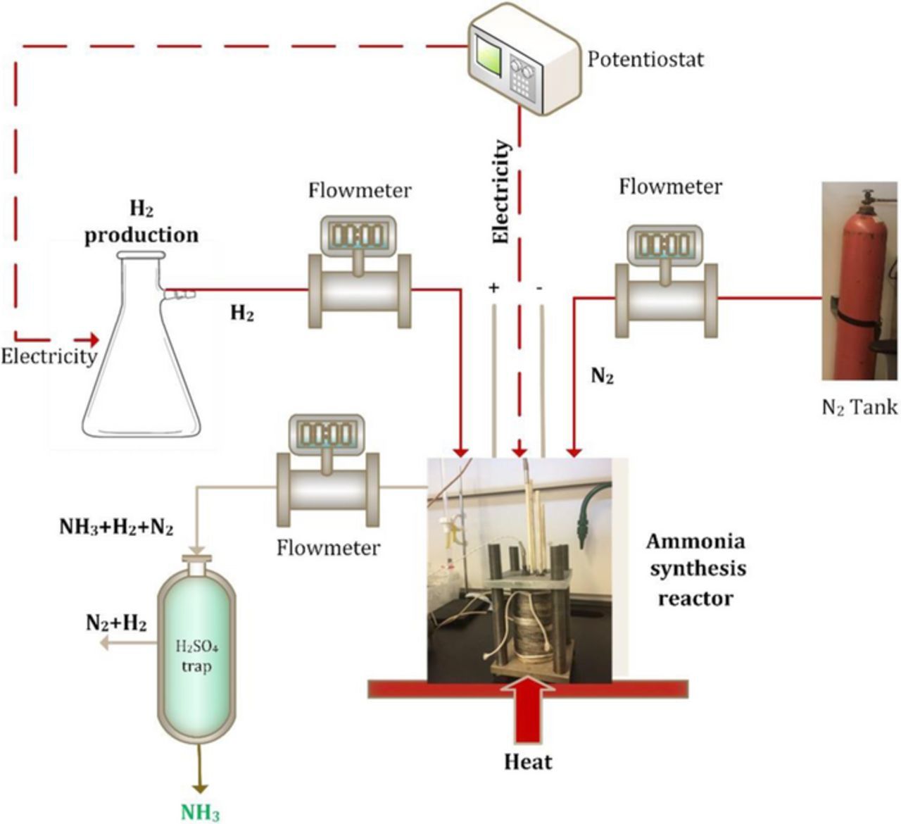
Figure 3. The complete sketch of the experimental setup for electrochemical ammonia synthesis.
The faradaic efficiency is calculated based on the moles of electrons consumed compared to the 3e−/NH3 equivalents produced. Thus, the faradaic efficiency of ammonia generation process is defined as follows:
![Equation ([5])](https://content.cld.iop.org/journals/1945-7111/164/8/H5036/revision1/d0005.gif)
where F is Faraday constant and i is the current density (A/cm2).
The energy efficiency of the ammonia production process is also calculated based on lower heating values of reacted hydrogen and ammonia, nitrogen enthalpy and electrical power input as follows:
![Equation ([6])](https://content.cld.iop.org/journals/1945-7111/164/8/H5036/revision1/d0006.gif)
where Wel is the total electricity input during the experiment calculated using the total charge, applied voltage and duration.
An uncertainty analysis for the experimental investigation is significant and necessary to understand and confirm the accuracy of the measured data and their results. In Table I, the measurement ranges and accuracies of all devices used in the experiments are listed based on the manufacturer datasheets.
Table I. The measurement range and accuracies of the measurement devices used in the experiments.
| Device | Measurement Range | Accuracy |
|---|---|---|
| Gamry Reference 30k Booster | ± 32 Volts and ±30 A | ±0.2% of scale ±0.2% of reading |
| OM-DAQPRO-5300 Thermocouple | −250 to 1200°C | ±0.5% |
| Omega FMA-1600A Flowmeter (for hydrogen) | 0–100 SCCM | ±(0.8% of reading + 0.2% full scale) |
| Omega FMA1700/1800 Flowmeter (for ammonia) | 0–500 SCCM | ±1.5% of full scale, ±3% of full scale |
| Omega FMA-1600A Flowmeter (for nitrogen) | 0–100 SCCM | ±(0.8% of reading + 0.2% full scale) |
Results and Discussion
The pure alkali hydroxides NaOH and KOH each melt only at temperatures above 300°C. The individual melting temperatures of NaOH and KOH are 318°C and 406°C, respectively. Among various alternatives, these two salts melt at quite lower temperatures which is a highly desired property in order to decrease external heat energy input. Based on common materials, the NaOH-KOH eutectic is of particular attention and melts at 170°C. Ammonia synthesis rates increase when the molten hydroxide (NaOH-KOH) electrolyte is mixed with high–surface area Fe3O4 to provide iron as a reactive surface and when nitrogen and hydrogen are present in the reactor. The molten salt medium is supplied electricity between two nickel anode and cathode electrodes. The mixture is prepared in the beginning by simply adding NaOH and KOH pellets in the reactor. After the salts melt, nano-Fe3O4 is added to the electrolyte and then stirred. When the mixture is ready, the lid is tightly closed and sealed. In order to yield NH3 in the reactor, H2, N2 and nano-Fe3O4 are simultaneously needed.
Table II shows the experimental conditions for four different runs. Experiment 2 is performed at constant applied potential of 1.5 V whereas the others are performed at constant current in galvanostatic mode. The temperatures given in the table are average temperatures because, the temperature controller is on/off type and keeping the temperature constant causes fluctuations. For each run, different ammonia trapping H2SO4 solution is used. The unreacted H2 is also measured using a hydrogen sensor embedded to Arduino board which shows the portion of H2 which does not react.
Table II. Experimental conditions for the NH3 synthesis process.
| Experiment # | Temperature (°C) | Duration (min) | Current density (mA/cm2) | Voltage (V) |
|---|---|---|---|---|
| 1 | 210 | 15 | 2 | 1.4 |
| 2 | 255 | 30 | 3 | 1.5 |
| 3 | 215 | 45 | 2 | 1.3 |
| 4 | 220 | 25 | 2.5 | 1.55 |
Note that water is not preferred to be added into the molten salt mixture because NH3 is soluble in water which may cause some of the formed ammonia to be dissolved in the eutectic mixture before arriving the ammonia collection tank.
The required cell voltage to initiate the reaction of nitrogen and hydrogen in molten hydroxide at 210°C in the existence of nano-Fe3O4 is measured to be on average 1.4 V when the applied current is 200 mA between the 100 cm2 Ni electrodes in the molten NaOH-KOH electrolyte. The potential increases to 1.54 V when the current density is increased to 2.5 mA/cm2 at 220°C as shown in Fig. 4. At 2 mA/cm2 and 210°C, ammonia is synthesized at a rate of 6.54 × 10⁻¹⁰ mol/s cm2. At 2.5 mA/cm2 and 220°C, the ammonia evolution rate decreases to 4.9 × 10⁻¹¹ mol NH3/s cm2. At 215°C in a eutectic Na0.5K0.5OH electrolyte with suspended nano-Fe3O4, it is observed that at 2 mA/cm2 applied current, NH3 is generated with a faradaic efficiency of about 6.3%, which declines to about 0.56% at 2.5 mA cm2 when the reactor temperature is 220°C. The constant current electrolysis at 2 mA/cm2 and 2.5 mA/cm2 are driven at 1.3 V and 1.54 V, respectively at different temperatures as depicted in Fig. 4.
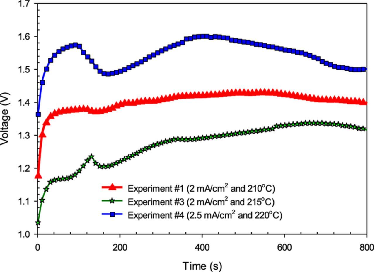
Figure 4. The relationship between voltage and time during several experimental runs at different applied currents and temperatures for electrochemical synthesis of NH3 using N2 and H2 with nano-Fe3O4 in a molten salt hydroxide electrolyte.
It is also observed in the experiments that even though the reactor temperature is below 200°C, ammonia is generated with a similar production rate to above 200°C. The fluctuations in the potentials are caused by the temperature on/off processes to keep the temperature constant during the experiments. When the heater is on, the required potential to drive the reaction decreases as seen in Fig. 4. The experimental runs (i.e., #3 and #4) are carried out in longer periods of time where they correspond to 2500 s and 1500 s for run #3 and run#4, respectively. The potential gradually declines from 1.6 V to 1.5 V during the experiment at constant current density of 2.5 mA/cm2. It is observed in the experiments that lower current density and lower temperature improve the stability of the rate of NH3 evolution.
Fig. 5 shows the current density across the electrodes of the reactor when constant voltage of 1.5 V is applied. In this case, on average 3 mA/cm2 current density is measured where the reaction temperature is considerably higher than other experiments corresponding to about 255°C. The greater ammonia generation rate at lower voltages can be because of the lower hydrogen ion stream at the cathode which provides more time for generation of ammonia according to reaction.
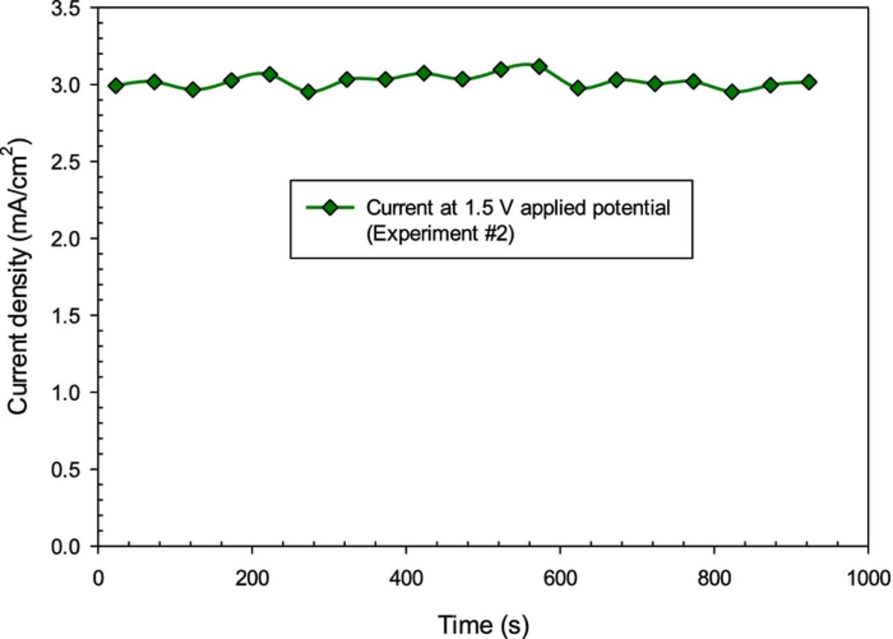
Figure 5. Current density at 1.5 V applied voltage for 100 cm2 Ni electrodes of electrochemical NH3 synthesis reactor.
Higher NH3 synthesis rates are obtained within the first hour of the experiments as seen in Fig. 6. By the end of the experiment which is close to about two hours, 5.69 mL of NH3 is formed. Further studies to enhance the stability of NH3 generation rate are considered for future work.
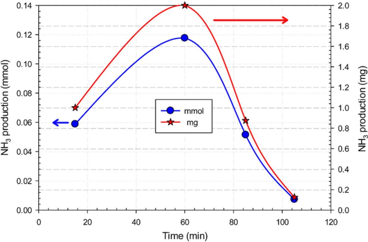
Figure 6. Cumulative NH3 production amount by electrochemical synthesis using N2 and H2 with nano-Fe3O4 in a molten salt hydroxide electrolyte.
The calculated faradaic and energetic efficiencies of ammonia evolution at different temperature levels and conditions in NaOH-KOH molten electrolyte are comparatively illustrated in Fig. 7. The generated NH3 is trapped and measured in a room temperature dilute H2SO4 trap. A non-dilute H2SO4 trap is also tried before the experiments reported here to understand the absorptivity of the solution. However, the ammonia readings were not successful in this case. Hence, dilute H2SO4 solutions are utilized for the reported experiments. The conversion efficiency is not only dependent on the hydrogen amount but also amount of catalyst available to stimulate the conversion of N2 and H2 into NH3. In order to make sure that there is enough N2 to be reacted with supplied H2, the supplied volume of N2 is kept quite higher than H2.
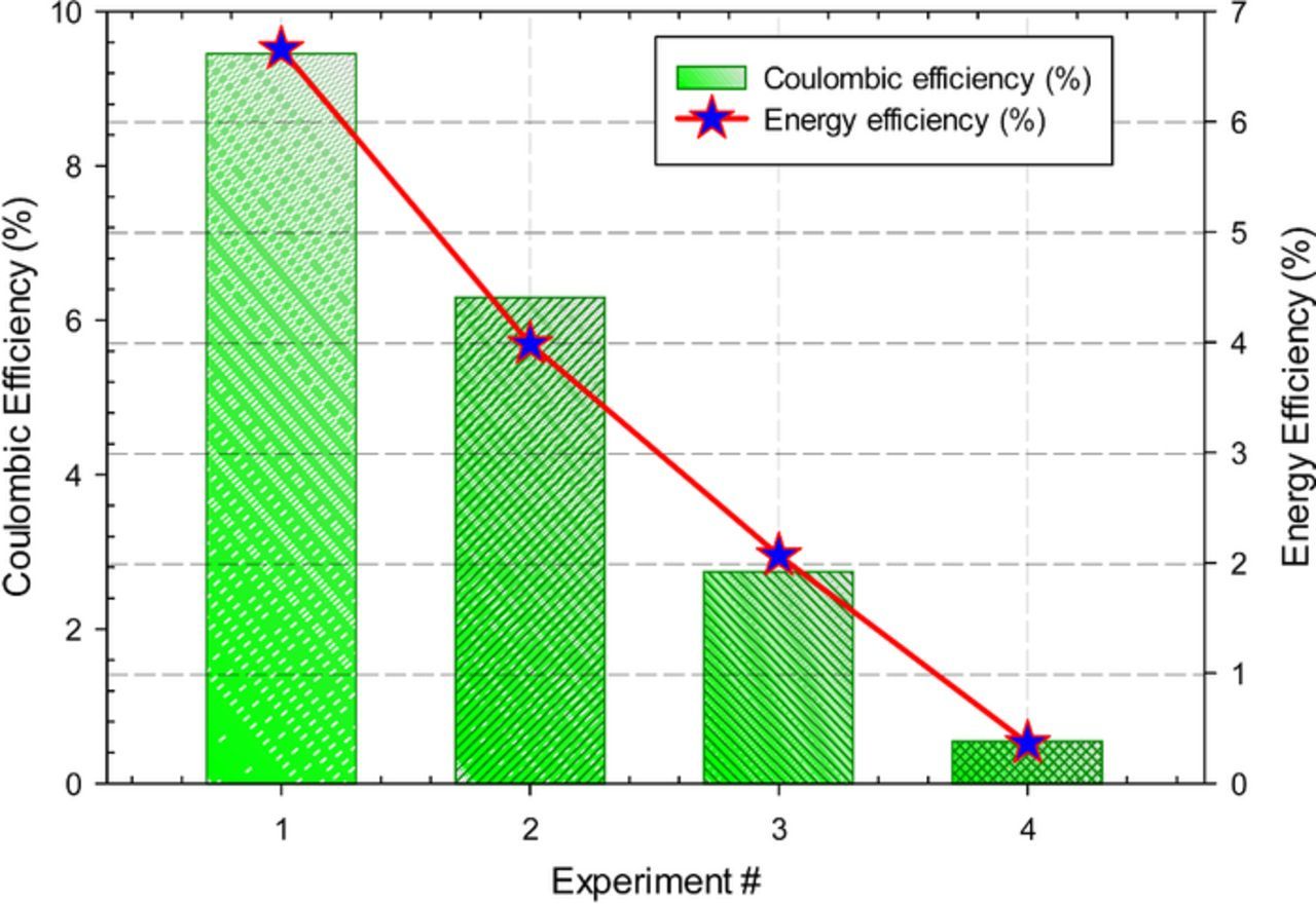
Figure 7. Faradaic and energy efficiencies of several experimental runs for electrochemical NH3 synthesis using N2 and H2 with nano-Fe3O4 in a molten salt hydroxide electrolyte.
In order to understand the current-voltage characteristics at lower temperature levels such as 200°C, the applied potentials are varied between 1.1 V and 1.5 V as shown in Fig. 8. At 200°C and 1.3 V, the average current density is 2.16 mA/cm2 whereas it is about 2 mA/cm2 at 215°C. The given temperatures and current densities are the average values where there are fluctuations because of the temperature controller.
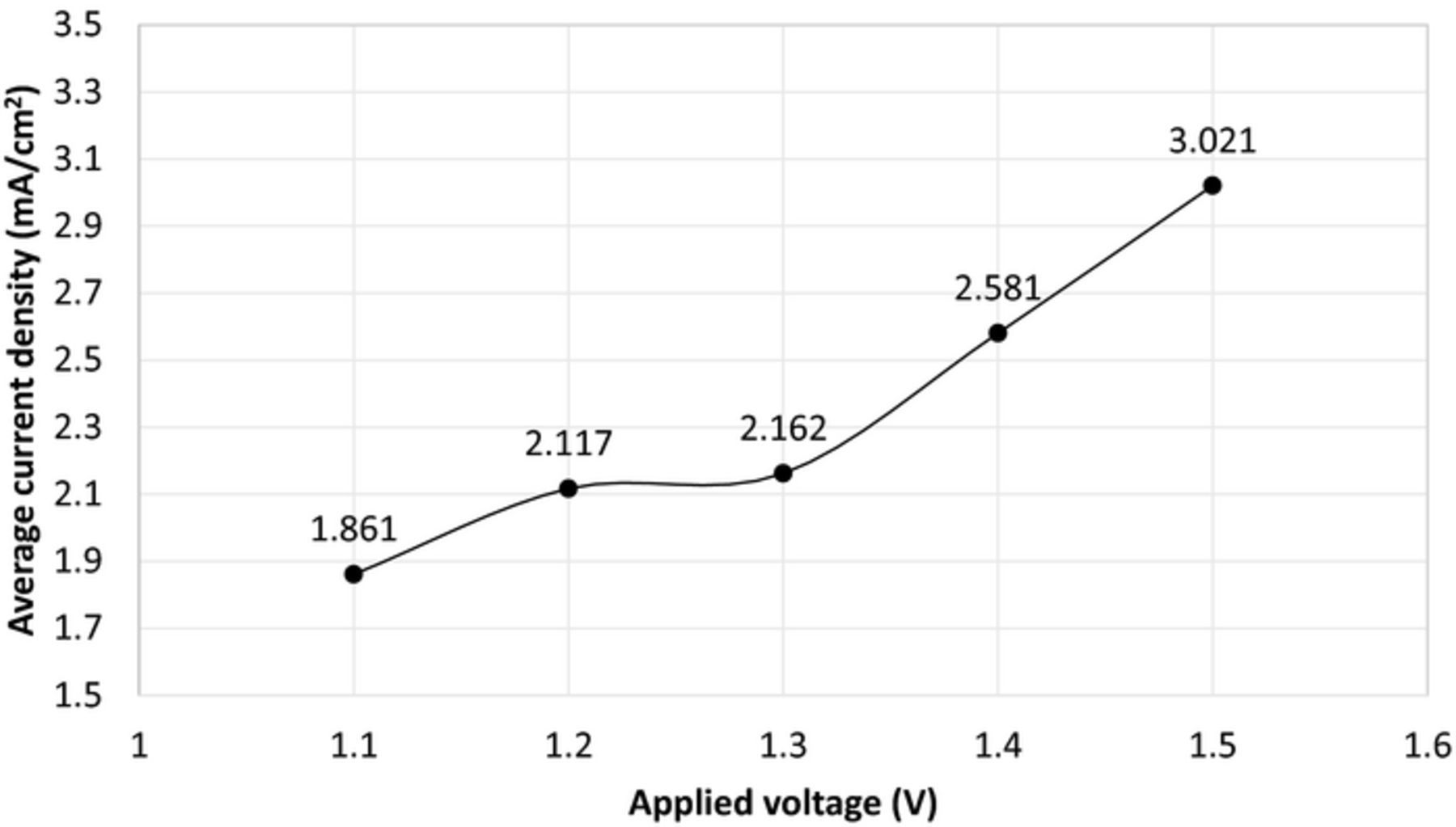
Figure 8. Applied potential-current density relations at 200°C for electrochemical NH3 formation using N2 and H2 with nano-Fe3O4 in a molten salt hydroxide electrolyte.
The variations of NH3 formation rates at different current densities and temperature levels are comparatively shown in Fig. 9. The figure reveals that the temperature and current density are not the sole parameters affecting the performance of the reaction. At higher current densities of 3 mA/cm2 and at higher temperatures of 255°C, the NH3 formation rate is high corresponding to about 6.6 × 10⁻¹⁰ mol/s cm2. The yielded efficiencies and production rates are summarized in Table III. The individual uncertainties of the components are obtained by means of the law of propagation of uncertainties. The calculated total uncertainties for each measurement parameter are shown in Table IV. Since the uncertainties are calculated based on the reference value, the values in the tables can be represented in percentage. Therefore, the total uncertainty for the faradaic efficiency is calculated to be about 1.6% whereas it is about 2% for energy efficiency. There are very minor changes in the uncertainty levels for different experimental runs because the uncertainty is mainly caused by the ammonia measurement flowmeter.
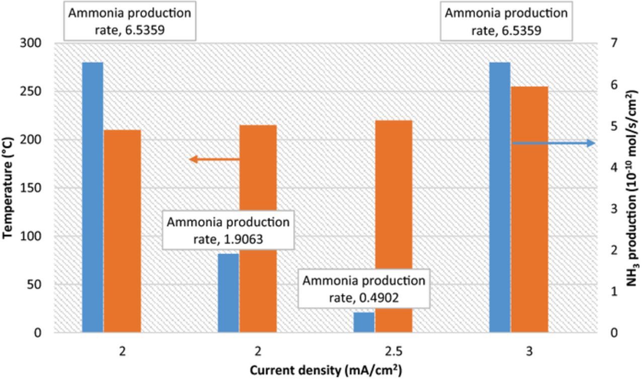
Figure 9. Change of electrochemical NH3 formation rates depending on the applied current densities and reactor temperature using N2 and H2 with nano-Fe3O4 in a molten salt hydroxide electrolyte.
Table III. Summary of the experimental results showing the NH3 formation rates and efficiencies.
| Experiment # | NH3 formation rate (mol/s/cm2) | NH3 mass flow rate (g/min) | Faradaic efficiency (%) | Energy efficiency (%) |
|---|---|---|---|---|
| 1 | 6.54 × 10⁻¹⁰ | 6.67 × 10⁻⁵ | 9.46 | 6.66 |
| 2 | 6.54 × 10⁻¹⁰ | 6.67 × 10⁻⁵ | 6.31 | 3.99 |
| 3 | 1.91 × 10⁻¹⁰ | 1.94 × 10⁻⁵ | 2.76 | 2.07 |
| 4 | 4.90 × 10⁻¹¹ | 5.00 × 10⁻⁶ | 0.57 | 0.36 |
Table IV. The uncertainty ranges of the experimental results.
| Measurement Parameter | Reference Value | Relative bias error | Relative precision error | Uncertainty |
|---|---|---|---|---|
| Voltage | 1.5 V | 0.2% | 0.022% | 0.2% |
| Current | 0.2 A | 0.2% | 0.013% | 0.2% |
| Temperature | 200°C | 0.5% | 0.008% | 0.5% |
| Volume flow rate (hydrogen) | 15 SCCM | 0.8% | 0.052% | 0.8% |
| Volume flow rate (ammonia) | 30 SCCM | 1.5% | 0.041% | 1.5% |
| Volume flow rate (nitrogen) | 80 SCCM | 0.8% | 0.014% | 0.8% |
Although the heating process is not taken into account in the efficiency calculations here, it is noted that the associated energy costs with medium/high temperature levels are also significant for this type of electrochemical ammonia synthesis systems. In order to reach the reaction temperatures, the heating tape (model number: STH051-080) used in the experiments is purchased from OMEGA Engineering Inc. having a power rate of 620 W and power density of 13 W/in2. After the temperature level is increased to the desired reaction temperature, the temperature controller turns on about 5 min intervals to maintain the temperature. In case the required heating could be recovered by excess or waste heat from any energy system (such as solar thermal or nuclear, the process would be more economic and effective.
The differentiations might be caused by the catalyst saturations as well as the changes in supplied H2 rates. The effects of catalyst quantity and type of electrodes are likely to be investigated in the future work. Furthermore, the electrochemical ammonia synthesis reactor is integrated to photoelectrochemical hydrogen production cell1 to develop a clean and environmentally friendly ammonia production technique.
Conclusions
The electrochemical synthesis of NH3 is a promising alternative to conventional energy intensive NH3 production plants. Using renewable energy resources to drive the electrochemical NH3 synthesis, the carbon footprint of current NH3 production industry can be significantly lowered. Electrochemical NH3 synthesis routes offer higher integrability to stand alone and distributed NH3 production which is important to provide a carbon free fuel for various sectors. In this study, NH3 is electrochemically generated at ambient pressure without a necessity of huge compressors, using H2 and N2 in a molten hydroxide medium with nano-Fe3O4 catalyst. The reaction temperature is varied in the range of 200°C to 255°C to investigate the impact of temperature on NH3 production rates. Having non-corrosive and high surface area nickel mesh electrodes allows to generate more NH3. The maximum faradaic efficiency is calculated as 9.3% with a reaction temperature of 210°C. The NH3 formation rate is determined to be 6.53 × 10⁻¹⁰ mol/s cm2 at 2 mA/cm2 current density. The lower current densities succeeded to generate higher NH3 and increasing the reaction temperature lowered the required potential to drive the reaction. The enhancements in the reactor design will allow better efficiencies in the near future. The possible issues being faced in the molten salt electrolyte based electrochemical NH3 synthesis is expected to further be resolved by way of not only the addition of more appropriate additives but also the continuous optimization of reactor configuration.
List of Symbols
| e | Charge of an electron (1.60217657 × 10¹⁹ C) |
| F | Faraday constant (C/mol) |
| h | Enthalpy (kJ/kg) |
| i | Current density (A/m2) |
| M | Molarity (M) |
 |
Mass flow rate (g/s) |
 |
Mol flow rate (mol/s) |
| t | Time (s) |
| V | Volume (L) |
 |
Work rate (W) |
Greek
| η | Efficiency |
Subscripts
| el | Electricity |
Acknowledgment
The authors acknowledge the support provided by the Natural Sciences and Engineering Research Council of Canada.