Abstract
In the current research, ruthenium stood a conspicuous dopant for TiO2 nanoparticles, to enhance its catalytic activity. The characterization of synthesized nanoparticles was accomplished by utilizing XRD, SEM, EDX and TEM analysis. The sensing surface morphology was studied by AFM analysis. Further, we established the electrochemical behavior and detection of flufenamic acid (FFA) by utilizing ruthenium doped TiO2 nanoparticles modified carbon paste electrode (Ru-TiO2/CPE) at pH 6.0 by employing different voltammetric techniques. Modification enhances the electro-oxidation of flufenamic acid with increased current intensity. The influence of parameters like scan rate, pH, accumulation time, amount of the modifier and concentration on the peak current of the drug were studied. The effect of FFA concentration variation was studied using square wave voltammetric (SWV) technique and got lowest detection limit compared to reported techniques. The fabricated sensor was employed for the determination of flufenamic acid in biological samples.
Export citation and abstract BibTeX RIS

This is an open access article distributed under the terms of the Creative Commons Attribution Non-Commercial No Derivatives 4.0 License (CC BY-NC-ND, http://creativecommons.org/licenses/by-nc-nd/4.0/), which permits non-commercial reuse, distribution, and reproduction in any medium, provided the original work is not changed in any way and is properly cited. For permission for commercial reuse, please email: oa@electrochem.org.
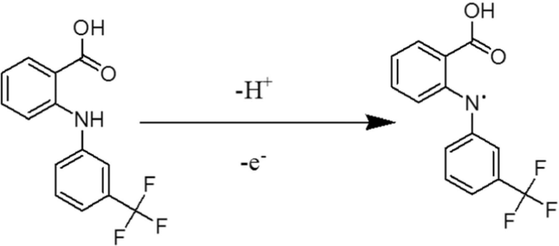
Flufenamic acid (FFA), N-(α,α,α-trifluoro-m-tolyl) an anthranilic acid derivative (Scheme 1), is an effective analgesic, an anti-inflammatory and antipyretic agent used for the relief of pain and inflammation associated with musculoskeletal and joint disorders, peri-articular and soft tissue disorders, antirheumatic therapy.1,2 Monitoring of therapeutic drug habitually necessitates its detection in biological fluids.
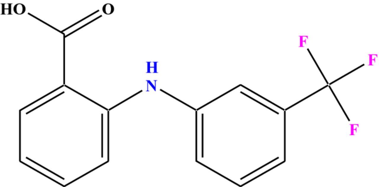
Scheme 1. Chemical structure of Flufenamic acid (FFA).
Many analytical methods based on different principles, such as spectrophotometry,3–6 spectrofluorimetry,5,11 fluorescence spectrometry,7–10 flow injection analysis,11,12 chromatography13–15 have been developed for the analysis of flufenamic acid along with its derivatives. Capillary electrophoresis16–18 is an alternative methodology for the separation and detection of FFA. However, these methods are well-demonstrated and broadly accepted, but they require moderately costly equipment, laborious sample pretreatment, specialized expertise, high cost and are time-consuming which make them unsuitable for routine analysis. Few voltammetric studies5,19 were also carried out by utilizing cyclic voltammetry and adsorptive voltammetry. Though, these sensors suffer from the less sensitive, poor long-term stability, lack of surface renewability, etc.
As of late, research developed, aiming at the construction and the characterization of the electrodes composed of carbonaceous materials because of their rich surface chemistry, lower background current, wider potential window, uncomplicated surface renewal and low detection limit properties.20–24 The fabrication of the working electrode with nanoparticles enhances peak current, sensitivity, reproducibility.25,26 In current science and technology, one of the crucial uniqueness is to survey and to discover the new efficient materials as electrode surface modifiers.
In general, new types of sensor devices are the outcome of the synthesis and preparation of innovative modifiers. In this regard, as electrode surface modifiers, TiO2 nanoparticles captured the copious interest of researchers and a considerable amount of research was executed in the previous decades, due to its photocatalytic effect, porosity, steadiness, crystallinity, widespread bandgap, high surface area and low toxicity.27–29 Nonetheless, the narrow photocatalytic area, large band hole and poor adsorption limit due to the short existence of electron-hole pairs are the significant drawbacks of TiO2 nanoparticles.30 The augment in the efficiency of TiO2 such as to entrap the charge carrier is achieved by doping with transition metals such as silver (Ag), copper (Cu), ruthenium (Ru) etc..31–33 Actually, on the semiconductor surface, dopants act as an electron sink which diminishes the electron-hole pair recombination.34–37 In this work, ruthenium was utilized as a dopant for TiO2 based nanoparticles to boost the area of the sensing surface, to reduce the recombination of the photogenerated e− and H+ and in the visible light region to extend the absorption of light.38
From the literature survey, we found that there is a gap in FFA determination in trace quantity. Therefore in this study, an incredible modifier i.e. ruthenium doped TiO2 nanoparticles (Ru-TiO2) was synthesized by liquid impregnation (LI) method, characterized by SEM, XRD, EDX and TEM to understand the fundamentals of the sensor material. This electrochemical study accentuates the enhanced sensing ability of ruthenium doped TiO2 nanoparticles modified carbon paste electrode (Ru-TiO2/CPE) compared to carbon paste electrode (CPE) and TiO2 nanoparticles modified carbon paste electrode (TiO2/CPE) toward FFA detection. The performance of Ru-TiO2/CPE is demonstrated by the determination of FFA in spiked human urine samples as well. We received excellent recoveries from urine and a good percentage of relative standard deviation (RSD) values indicate the supremacy with regard to reproducibility and repeatability of the Ru-TiO2 modified sensor.
Experimental
Instrumentation and chemicals
The crystal structure and particle size of Ru-TiO2 nanoparticles were determined by scanning electron microscope (SEM) (JEOL JSM-6360), transmission electron microscope (TEM) Philips (CM200), X-ray diffraction (XRD) analysis (Phillips PW1729, Cu kα). The surface morphology of the sensor was examined using atomic force microscopy (AFM). Voltammetric measurements were carried out in an electrochemical analyzer (CHI Company, D630, USA) with three electrode system, namely Ru-TiO2/CPE as the working electrode, a platinum wire as the counter electrode, and an Ag/AgCl (3.0 M KCl) as the reference electrode, respectively. Before each measurement, the modified and unmodified CPE surfaces were regenerated by renewing and polishing them on filter paper and washed with double distilled water. The pH measurements were performed using Elico pH meter (Elico Ltd., India).
FFA was purchased from Sigma-Aldrich and was used as received without any further purification. A stock solution of FFA (0.1 mM) was prepared by dissolving an appropriate amount of pure powdered sample in ethanol and stored at low temperature. Phosphate buffer saline (PBS) solution (I = 0.2 M) of different pH ranging from 3.0–11.2 was used as supporting electrolyte.39 Mineral oil (Nujol oil) was procured from Fluka. Double distilled water was used in this work. All other solvents and chemicals used were of analytical reagent grade.
Ru-TiO2 nanoparticles preparation
A simple liquid impregnation process was utilized to prepare the ruthenium (Ru) doped TiO2 nanoparticles (anatase). An accurate amount of (0.8%) RuCl3.3H2O (SRL, India) was weighed and dissolved in 100 ml of 0.2 M HCl solution in a clean beaker (500 ml), followed by the addition of 1.0 g TiO2 nanoparticles (Anatase). Then, the subsequent slurry was carefully stirred using a magnetic stirrer for 3 hours and kept for 24 hours until it settles. The slurry was dried for 24 hrs in an oven at 80°C and ground in a mortar to get fine powder. The nanoparticles were calcined at 400°C, which is below the phase transformation temperature of TiO2.40,41
Preparation of modified electrode
By using a mortar and pestle, the preparation of unmodified CPE was done via mixing graphite powder and mineral oil (7:3). For self-homogenization, the paste was allowed to stand for 24 hours. The CPE modified with 0.8% Ru-TiO2 was prepared by homogeneous mixing of an appropriate amount of graphite powder: Ru-TiO2 nanoparticles: mineral oil in an agate mortar. In a polytetrafluoroethylene tube (PTFE), the resulting paste was packed firmly and the surface was smoothened by polishing against the filter paper. To renew, the used paste was carefully detached from PTFE. Activation of the working electrode surface was done by recording cyclic voltammograms (CV) in PBS of pH = 6.0 between 0.0 V to 1.2 V until a steady voltammogram was obtained.
The dynamic surface area of the sensing platform was calculated by using Randles - Sevcik equation; area was investigated utilizing cyclic voltammetric technique, 1.0 mM K3Fe (CN)6 as a test solution and 0.1 M KCl as supporting electrolyte, at different sweep rates in.42 At T = 298 K and for a reversible process the equation is as follows:
![Equation ([1])](https://content.cld.iop.org/journals/1945-7111/164/5/B3036/revision1/d0001.gif)
The area of the electrode surface is signified as A, the diffusion coefficient as D0, i.e. 7.6 × 10⁻⁶ cm2 s−1, sweep rate as ν, and C0* is the concentration of K3Fe (CN) 6. From the slope of the plot of Ip vs. ν1/2, the surface area of the bare electrode was found to be 0.042 cm2 and for the modified electrode, the calculated surface area was 0.36 cm2.
Analysis of human urine samples
Urine samples were obtained from two healthy volunteers and at room temperature (25 ± 0.1°C) was centrifuged (4383 G) for 5 minutes. The obtained samples undergo two-fold dilution, using PBS of pH 6.0 and the test solution was prepared by spiking the filtrate with the known amount of FFA (0.1 mM).
Results and Discussion
Characterization of Ru-TiO2 nano particles
Surface characterization plays a very important role in our understanding of the fundamentals and performance of fabricated sensors. The characterization of the modifier; Ru-TiO2 nanoparticles was achieved by utilizing Scanning electronic microscopy (SEM), Energy-dispersive X-ray spectroscopy (EDX), X-ray diffraction (XRD), and transmission electron microscope (TEM). The morphology of the sensor platform was analyzed by utilizing atomic force microscopy (AFM) in air.
Figure 1A. and Figure 1B. represents the SEM images of the 0.8% Ru-TiO2 and TiO2 nanoparticles respectively, which describes the characteristic shape and size of the nanoparticles. It shows the haphazard aggregates of Ru-TiO2 nanoparticles, which results in a high surface area. The aggregate formation could be due to the incorporation of Ru in the starting solution during nucleation process.
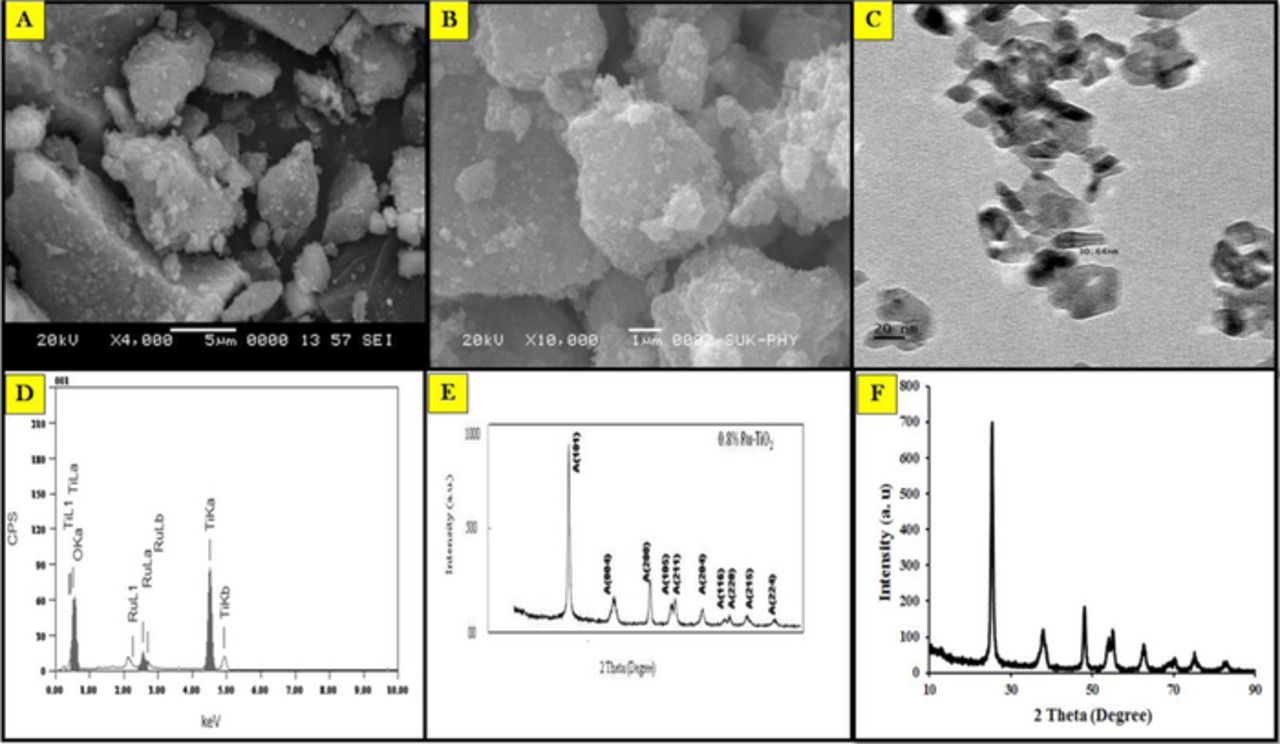
Figure 1. Characterization of nanoparticles: (A) SEM image Ru-TiO2 nanoparticles; (B) SEM imageTiO2 nanoparticles; (C) TEM image; (D) EDX spectrum of the synthesized Ru-doped TiO2 nanoparticles; (E) XRD pattern of Ru-TiO2 nanoparticles; (F) XRD pattern of TiO2 nanoparticles.
TEM images display the aggregates of Ru-TiO2 nanoparticles dispersed in a heterogeneous way. The barrel-shaped crystalline structures are clearly inspected in Figure 1C. The scattered dark minute spots observed were presumed to be Ru particles on TiO2 nanoparticles with a particular size of 10–15 nm breadth and length of 30–35 nm approximately.
The chemical composition of the modifier was studied by the EDX examination (Figure 1D). Three dissimilar X-ray forms related with O Kα, Ru Kα, and Ti Kα were detected in the EDX analysis.43 The peaks in the spectrum disclose that at 4.508, 0.525 and 2.558 keV, the existence of Ti, O, and Ru witnessed respectively. The atomic percentage (%) of Ti, O, and Ru was found to be 36.40, 62.79 and 0.81 correspondingly. The prepared nanoparticles were composed of Ti and O mainly with a little amount of Ru, exposed that the formation of non-stoichiometric Ru-TiO2 with oxygen vacancy, which leads to improved photo-catalytic activity.
The X-ray diffraction patterns of Ru-TiO2 and TiO2 nanoparticles (Figures 1E and 1F), shows as a function of reaction temperature. In the figure ten distinct peaks, equivalent to the (101), (004), (200), (105), (211), (204), (116), (220), (215), and (224) lattice planes, disclosing that the synthesized nanoparticles are in anatase form. Because of the low concentration of metal or may be due to the ultrafine dispersion of TiO2 nanoparticles, no metal peaks were observed. By applying Scherrer Equation the average particle sizes of prepared nanoparticles were calculated from full width half maximum of A (101) peak of anatase TiO2.44 The average particle size of TiO2 and 0.8% Ru–TiO2 were found to be 17.0 and 14.40 nm respectively.
In electroanalysis, the morphological study of the sensing base gives insight into the electrochemical properties of the electrode. The modified electrode characterization was done by using atomic force microscopy (AFM) in air. Figure 2. represents the AFM image of CPE and Ru-TiO2/CPE. The roughness of the electrode surface and delta Z value (Delta Z is the difference in the sample height between the start and the end point), were obtained from the AFM topological images. The analyzed surface morphological characteristics of both unmodified and modified electrodes were listed in Table I.
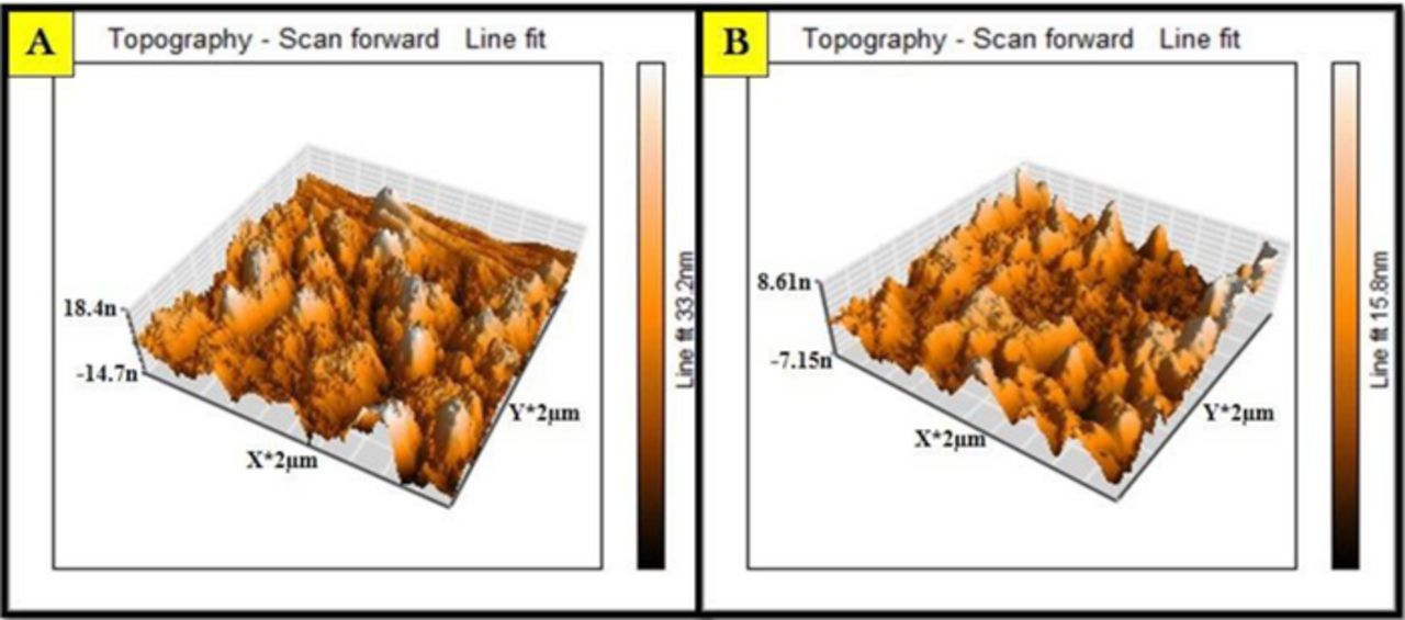
Figure 2. AFM image of (A) Unmodified carbon paste electrode; (B) Ru-TiO2 nanoparticles modified carbon paste electrode.
Table I. The surface morphological properties of CPE and Ru-TiO2/CPE by AFM analysis.
| Surface characteristics | CPE | Ru-TiO2/CPE |
|---|---|---|
| Scan size | 2.0 μm × 2.0 μm | |
| Total area roughness | 4.031 pm2 | 4.161 pm2 |
| Roughness average value (Sa) | 4.443 nm | 2219 pm |
| Root mean value (Sq) | 5.6043 nm | 2.901 nm |
| Peak value height (Sy) | 39.382 nm | 39.913 nm |
| Peak height (Sp) | 21.786 nm | 32.615 nm |
| Valley depth (Sv) | −17.596 nm | −7.297 nm |
| Mean value (Sm) | −2.873 fm | −2.872 fm |
| Delta z value (ΔZ) | 4.432 nm | 3.317 nm |
Effect of accumulation time
The accumulation time plays a significant role in the transport of analyte from the test solution to the modified electrode. Thus the impact of accumulation time was carried out for 0.1 mM FFA in a range of 0–120 s utilizing CV technique. There was a gradual increase in the accumulation time from 0 to 30 s and beyond 30 s peak currents were almost constant (Figure 3). The maximum peak current was observed at 30 s; hence it opted for further studies.

Figure 3. Variation of cyclic voltammetric anodic peak current for 0.1 mM FFA with accumulation time.
Effect of amount of Ru-TiO2 nanoparticles
The effect of the amount of 0.8% Ru-TiO2 nanoparticles as a modifier in CPE was investigated. It was found that the anodic peak current was increased by the amount of Ru-TiO2 nanoparticles up to 0.5% (Figure 4), further saturation occurred. The enlarged measure of modifier onto the sensing base may resist the easy electron transfer and as a result, the peak current of FFA was declined after addition of 0.5% modifier. Therefore, 0.5% Ru-TiO2 nanoparticles were preferred as the optimum amount for the preparation of the Ru-TiO2/CPE.
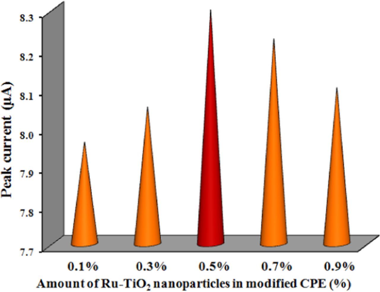
Figure 4. Variation of cyclic voltammetric anodic peak current for 0.1 mM FFA with the modifier amount in RuTiO2-CPE.
Augmentation of the quality of CPE with the modification
Figure 5 shows the cyclic voltammetric responses 0.1 mM FFA at the surface of unmodified and modified CPEs, which heightens the boosted catalytic activity of Ru-TiO2/CPE sensor compared to TiO2/CPE and CPE, toward FFA detection in pH 6.0 at a scan rate of 0.05 Vs−1. The key difference between these voltammograms was a slightly negative shift in the peak potential value and an enhanced magnitude of background current. The current system is reversible one, showing an anodic peak (Ep = 720 mV) as well as a cathodic peak (Ep = 322 mV). However, an extremely weak wide cathodic peak with slightly high potential and the low current was observed at the exposed surface of sensors utilized in this work such as TiO2/CPE and CPE. This mechanism is due to the sluggish electron exchange kinetics. The tailoring of CPE sensing base with Ru-TiO2 nanoparticles results fast electron transfer and consequently enrichment of the electrochemical reaction.45 Exploiting the high surface range provided by Ru-TiO2 nanoparticles and additionally FFA adsorption at the fabricated sensor.
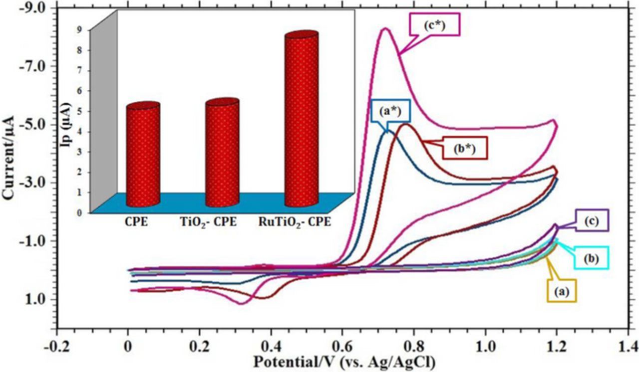
Figure 5. Voltammetric behavior of 0.1 mM FFA in pH 6.0, phosphate buffer (I = 0.2 M) at scan rate = 0.05 Vs−1; Acc. Time = 30 s: (a) blank CPE; (a*) CV of 0.1 mM FFA at CPE; (b) blank TiO2-CPE; (b*) CV of 0.1 mM FFA at TiO2-CPE; (c) blank RuTiO2-CPE; (c*) CV of 0.1 mM FFA at RuTiO2-CPE. Inset: Variation in peak current at different electrodes.
Effect of supporting electrolyte
The redox behavior of FFA was well allied with the pH medium of supporting electrolyte. To know the voltammetric response, the effect of pH solutions was studied at Ru-TiO2/CPE, in the range of 3.0–11.2 of 0.2 M PBS employing CV technique at 0.05 Vs−1scan rate (Figure 6). The study shows that the peak current is affected by the variation of solution pH (Figure 6B). The higher current intensity was observed at pH 6.0 and thus for further studies the working pH chosen was 6.0. In the reverse scan, one reduction peak was observed at lower pH. As the pH of the solution increased the magnitude of the cathodic peak decreased. The peak potential budged more negatively as the pH of the supporting electrolyte increases, which recommends the H+ ions involvement in the present system.46 The linear relationship between Ep and pH is expressed in Figure 6A.; with a regression equation Ep = −0.045 pH + 0.992; R2 = 0.985. From the equation, it can be seen that the slope value was nearly equals to 0.049, which demonstrates the Nernstian behavior for equal number of protons and electrons participation in the electro-oxidation of FFA.47 A probable reaction mechanism is proposed for an electrochemical oxidation of FFA at Ru-TiO2/CPE in PBS 6.0 pH.
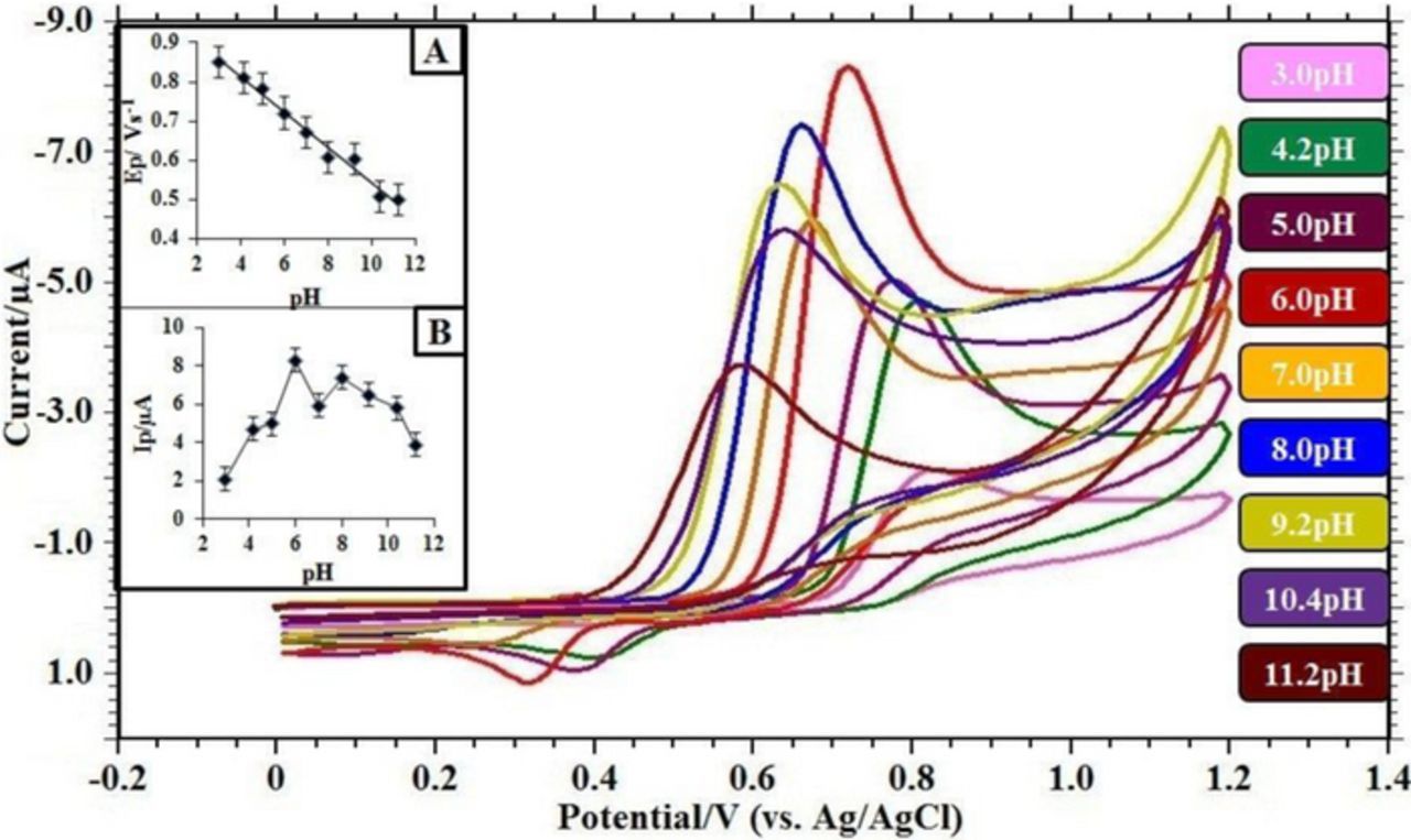
Figure 6. Cyclic voltammograms obtained for 0.1 mM FFA in buffer solution of different pH at Ru-TiO2/CPE; Scan rate = 0.05 Vs−1; Acc. Time = 30 s. (A) Variation of peak currents Ip/ μA of FFA with pH; (B) Influence of pH on the peak potential Ep/ V of FFA.
Effect of scan rate
To identify the clear electrochemical mechanism of this system, voltammograms were recorded on the new sensor surface, using CV technique by varying scan rates (Figure 7.). It was observed that the peak current (Ip) of the process varies linearly with the scan rate (ν) (Figure 7A). Further, the slope value of log Ip versus log ν, designates the electrode process found here is the mixed adsorption-diffusion controlled process (Figure 7B).48,49 This type of process may be associated to the adsorption of the analyte moiety i.e. FFA at the electrode base and then their diffusion through the bibulous sensing surface.50 The corresponding equation is as follows:


Figure 7. Cyclic voltammograms of 0.1 mM FFA in buffer solution of pH 6.0 (I = 0.2 M) at scan rate of: (1) blank; (2) 0.009; (3) 0.01; (4) 0.02; (5) 0.03; (6) 0.04; (7) 0.05; (8) 0.07; (9) 0.09; (10) 0.12; (11) 0.15; (12) 0.20; (13) 0.25 V s−1. Acc. Time = 30s. (A) Dependence of peak current Ip/ μA on the scan rate υ / Vs−1. (B) Plot of logarithm of peak current log Ip/ μA versus logarithm of scan rate log υ / Vs−1. (C) Plot of variation of peak potential Ep/ V with logarithm of scan rate log υ / Vs−1.
The relationship between peak potential (Ep) and log ν shows good linearity (Figure 7C) with the regression equation as follows:
The relationship between peak potential and scan rate for an electrode process can be expressed by Laviron's theory.51
![Equation ([2])](https://content.cld.iop.org/journals/1945-7111/164/5/B3036/revision1/d0004.gif)
Where α is the transfer coefficient, k° is the standard heterogeneous rate constant of the reaction; 'n' stands for a number of electrons transferred, 'υ' is the sweep rate and E° stands for the formal redox potential. Other symbols have their usual meaning. According to Bard and Faulkner,52 α can be calculated as,
![Equation ([3])](https://content.cld.iop.org/journals/1945-7111/164/5/B3036/revision1/d0005.gif)
Where Ep/2 is the potential where the current is at half the peak value. So, from this we got the value of α to be 0.5. k° was calculated to be 3.662 × 10³ s−1, from the intercept of Ep versus log υ. Further, the number of electron (n) transferred in the electro-oxidation of FFA was calculated to be 1.
Electrochemical mechanism
FFA showed one well-resolved anodic signal in all pH range studied. The pKa value of FFA is 6.8. Consequently, near pH 6.0 we can anticipate obtaining the oxidized form of FFA according to Scheme 2. In acidic medium, the oxidation of FFA undergoes a proton-dependent mechanism whereas, in abasic medium, no protons are involved in the rate determining step or before. As we know FFA is a diphenylamine which does not have substituent groups in the para position. The anodic peak could be attributed possibly due to the oxidation of the amine group contained in the structure of FFA. Based on all the observed results we postulated the probable mechanism as shown in Scheme 2.
Scheme 2. Possible electrode reaction mechanism of Flufenamic acid (FFA).
Analytical Applications
Effect of concentration variation
Figure 8 shows square wave voltammetry (SWV) curves of FFA at various concentrations from 3.0 × 10⁻⁶ M to 8.0 × 10⁻⁴M in PBS at pH 6.0. The SWV technique results in improved resolution because its charging current contribution to the background current is quite low. Under optimized conditions, the linear regression equation is Ip (μA) = 6.899 C (μM) + 1.204 with correlation coefficient of R2 = 0.987, indicates that the method can be applied in the FFA determination in different samples. The LOD and LOQ for the determination based on three and ten times of the blank standard deviation (3Sb, 10Sb) were 1.69 nM and 5.63 nM, respectively.53–55 Referring to the analytical performances of some recently published reports (Table II), the present work results very sensitive, selective method with low detection limit, which is possibly associated with high electrocatalytic and surface area effects of Ru-TiO2 modified CPE, suggesting that the developed sensor in this work can be served as a promising platform for FFA detection in low concentration.
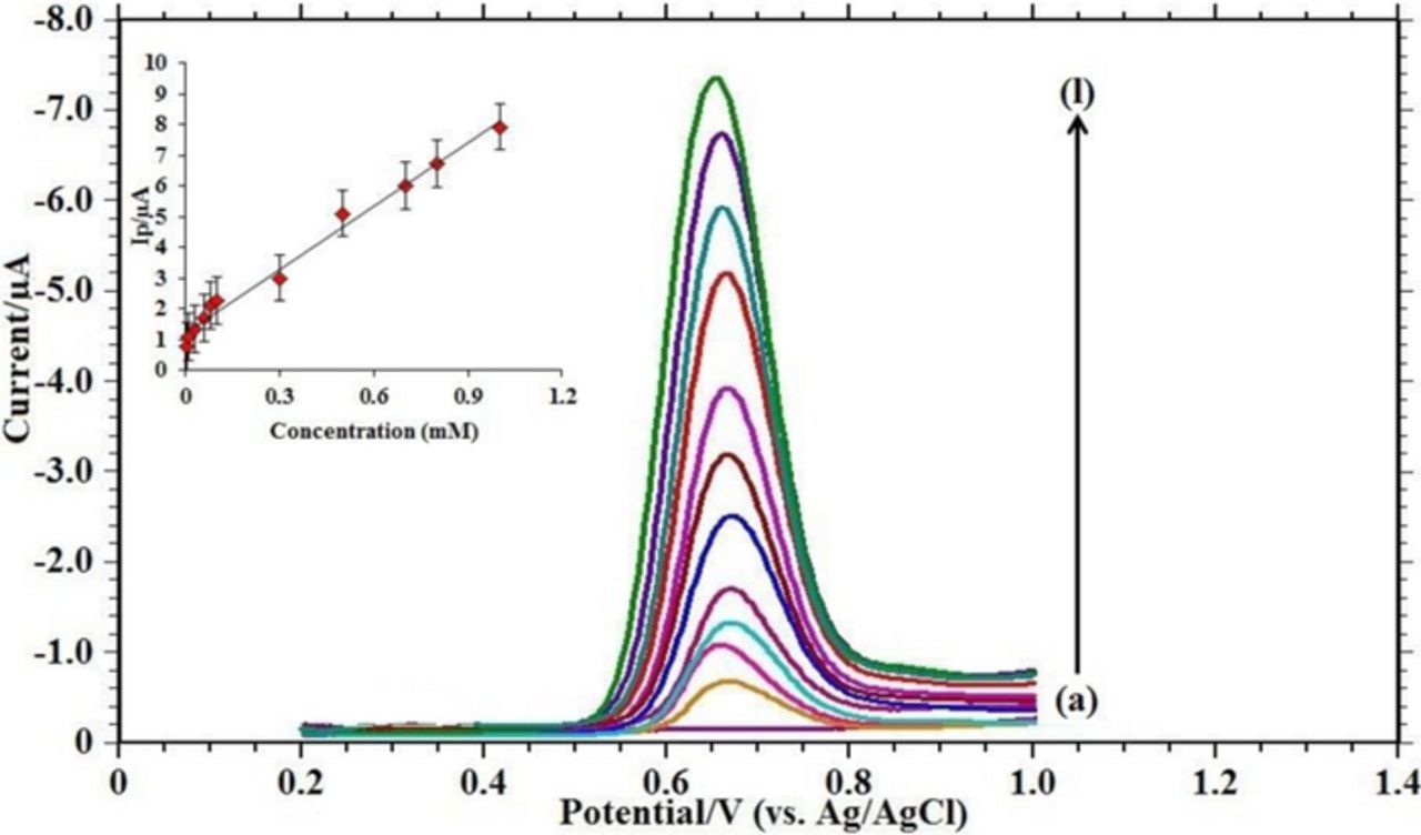
Figure 8. Square wave voltammograms with increasing concentrations of FFA in pH 6.0 phosphate buffer solution at Ru-TiO2/CPE with acc. time = 30s: (a) blank; (b) 5.0 × 10⁻⁶; (c) 1.0 × 10⁻⁵; (d) 3.0 × 10⁻⁵; (e) 6.0 × 10⁻⁵; (f) 8.0 × 10⁻⁵; (g) 1.0 × 10⁻⁴; (h) 2.0 × 10⁻⁴; (i) 5.0 × 10⁻⁴; (j) 7.0 × 10⁻⁴; (k) 8.0 × 10⁻⁴; (l) 1.0 × 10⁻³. Inset: Plot of concentration (mM) versus peak current Ip/ μA.
Table II. Comparison of detection limits of flufenamic acid by different reported methods.
| Techniques | LOD (nM) | Reference |
|---|---|---|
| Voltammetry using HMDEa | 3.24 | 5 |
| Spectrofluorimetry | 0.54 | 5 |
| Capillary Electrophoresis | 0.97 | 17 |
| Adsorptive differential pulse voltammetry using CPEb | 10.8 | 19 |
| Adsorptive differential pulse voltammetry using in situ DTACc modified CPE | 0.64 | 19 |
| Square wave voltammetry using Ru-TiO2 nanoparticles modified CPE | 1.69 | [Present work] |
aHanging mercury drop electrode. bCarbon paste electrode. cDodecyltrimethyl ammonium chloride.
Effect of interferents
To examine the cause of the common metabolites on the peak potential and the peak current of FFA, excipients study has been carried out using the present modified sensor. The results are evidently specified that the drug FFA voltammetric response, does not suffer from the existence of potentially interfering substance (Figure 9). Hence, the modified sensor can be efficiently utilized for the detection of FFA.
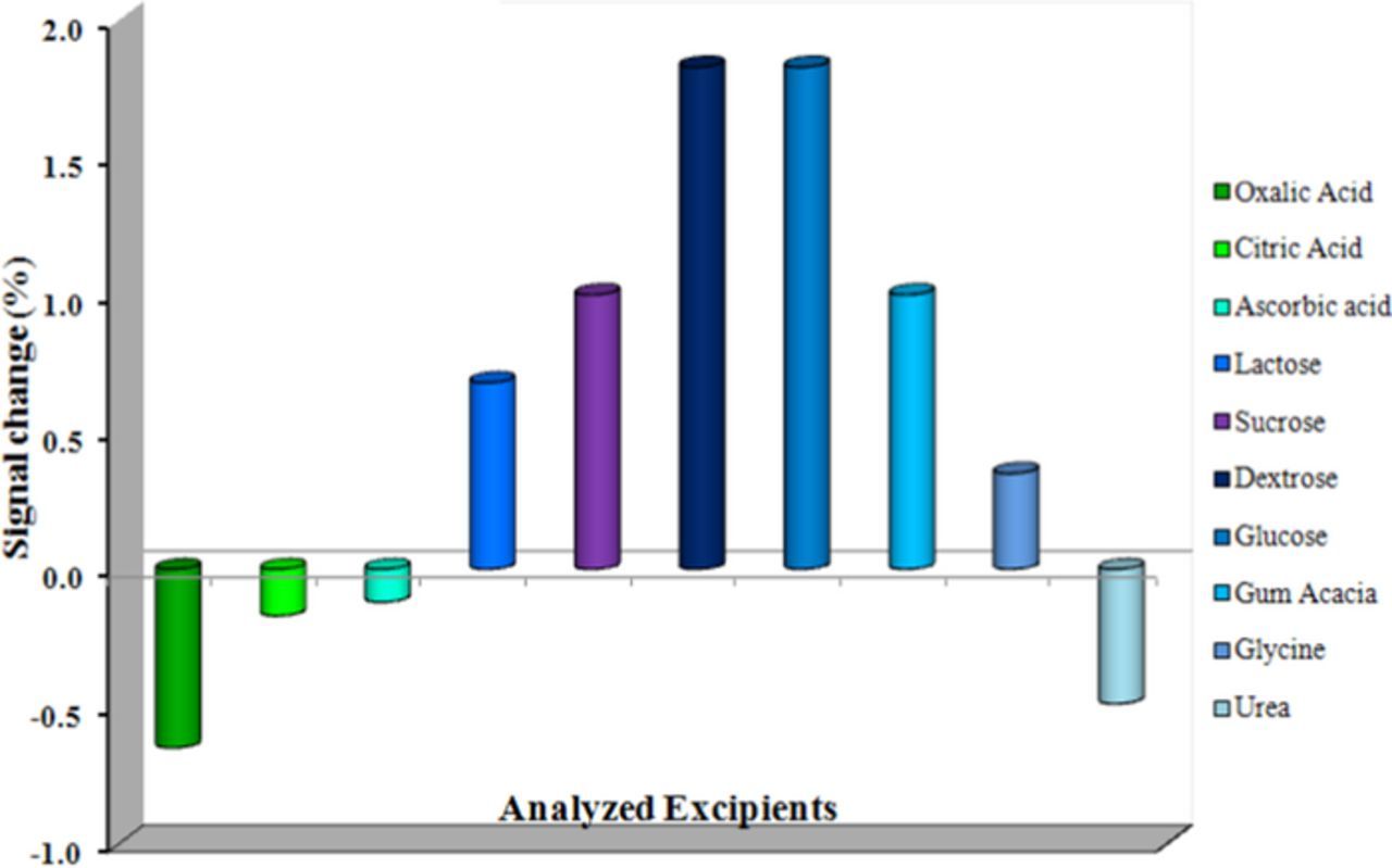
Figure 9. Influence of potential interferents on the voltammetric response of 0.1 mM FFA.
Detection of FFA in urine samples
No pre-extraction process was involved in urine sample analysis. The recovery studies were performed by spiking drug-free urine sample with known amount of FFA. The calibration plot was used for the determination of spiked FFA in a urine sample. The results showed that satisfactory recovery for FFA could be obtained (Table III).
Table III. Application of square wave voltammetry for the determination of flufenamic acid in spiked human urine samples.
| Urine | Spiked | Detected* | Recovery | ||
|---|---|---|---|---|---|
| Samples | (10−5 M) | (10−5 M) | (%) | RSD | % RSD |
| Sample 1 | 0.1 | 0.097 | 97.9 | 0.0185 | 1.85 |
| Sample 2 | 0.2 | 0.198 | 99.0 | 0.0183 | 1.83 |
| Sample 3 | 0.5 | 0.475 | 95.0 | 0.0190 | 1.90 |
Stability and reproducibility of Ru-TiO2/CPE
To assess the effectiveness of the fabricated electrode, steadiness, and repeatability studies were been carried out with 0.1 mM FFA. To check the stability, the prepared sensor conserved in an airtight container for fifteen days. The electrode retained 97.8% of its initial peak current response for a concentration 0.1 mM FFA. This discloses the long-term steadiness of the modified electrode.
The reproducibility of the electrode was as well investigated with the same sensor by the intra-day studies at a stable temperature. Five tedious measurements were recorded at a stable concentration of FFA (0.1 mM). Noticeable results with RSD % of about 2.52% suggested good reproducibility of the sensor for FFA detection. These results signify that the modified sensor has high stability and reproducibility in both the preparation procedure and determinations.
Conclusions
In the current research, Ru-TiO2 nanoparticles were synthesized by liquid impregnation method and characterized by XRD, SEM, TEM and EDX analysis. The prepared Ru-TiO2 nanoparticles were utilized for tailoring of modulated CPE. Thus formed sensor morphology was studied by AFM analysis and it displays an augmentation of selectivity and resolution in the voltammetric response for the determination of FFA at pH 6.0. From the obtained data, mixed adsorption-diffusion controlled process and one proton, one electron involvement was witnessed. A possible reaction mechanism was proposed. The present study is expedient due to the low detection limit, sensitivity, and selectivity, compared to earlier reports. This method has been successfully employed to analyze FFA in biological fluids. Furthermore, the analytical response was unaffected by the presence of common interfering agents in biological fluids.
List of Symbols
| A | surface area of the electrode (cm2) |
| C0* | concentration (mol dm−3) |
| D0 | diffusion coefficient (cm2s−1) |
| E0 | formal redox potential |
| Ep | peak potential (V) |
| F | faraday constant (C mol−1) |
| Ip | peak current (μA) |
| k° | standard heterogeneous rate constant (s−1) |
| m | slope of the calibration curve |
| n | number of electrons transferred |
| R | gas constant (J K−1mol−1) |
| S | standard deviation of the peak currents |
| T | temperature (K) |
Greek
| ν | scan rate (V s−1) |
| α | transfer coefficient |
Acknowledgments
One of the authors (Deepti S. Nayak) thanks, Department of Science and Technology, Government of India, New Delhi for the award of Inspire Fellowship in Science and Technology.