
Abstract
Sulfur-nickel foam cathode materials prepared by an in situ solution-based method were served as electrode of lithium-sulfur (Li-S) batteries. At the rate of 0.5 C, the Li-S cells deliver an initial discharge capacity of 1340 mAh g−1 and 493 mAh g−1 after 500 cycles. It is shown that these Li-S cells are of high rate stabilities with a nearly 100% stable coulombic efficiency at various rates from 0.1 C to 5 C. The electrochemical stability of Li-S batteries is mainly due to the strong binding between the highly dispersed sulfur and nickel foam skeletons.
Export citation and abstract BibTeX RIS

This is an open access article distributed under the terms of the Creative Commons Attribution 4.0 License (CC BY, http://creativecommons.org/licenses/by/4.0/), which permits unrestricted reuse of the work in any medium, provided the original work is properly cited.
Lithium-sulfur (Li-S) batteries have gained considerable attentions due to their high theoretical specific capacity (1675 mAh g-1), as well as abundant, cheap and environment friendly characters.1,2 However, the development of Li-S batteries is blocked by several problems such as the high solubility and mobility of lithium polysulfides in electrolytes. The diffusion of the dissolved polysulfides between the Li anode and cathode leads to shuttle between the two electrodes,3,4 which may cause the loss of active materials, low coulombic efficiencies and poor cyclability of Li-S batteries.5
Recent studies have shown that a metal can stabilize sulfur through chemical bonding6 and its metallic porous nanostructure can suppress the shuttle effect7 to attain the excellent coulumbic efficiency and cyclability. Based on the reactivity with sulfur,8 three-dimensional architecture and good electronic conductivity of nickel foam,9–11 here we present a sulfur-nickel foam cathode material for Li-S batteries. We will show that, since sulfur is highly and uniformly dispersed on nickel foam and bound in the interface of sulfur and nickel, cathode materials exhibit a stable electrochemical behavior. Moreover, the mechanism of nickel foam for optimization of the electrochemical performance is discussed.
Experimental
The sulfur-nickel foam cathode materials were synthesized by a facile in situ solution-based technique. Firstly, 10 g Na2S2O3 was dissolved in 50 mL water, in which nickel foam (120 PPI, 350 g m-2, 1.6 mm in thickness, and Φ10 mm in diameter) was added under ultrasonic action until it completely infiltrates. Then, hydrochloric acid aqueous solution (20 mL, 23%) was dropwise added, and the yellow sulfur precipitates formed immediately and stabilized on the surface of nickel foam. Here the content of sulfur was controlled by the amount of hydrochloric acid aqueous. After washing with water and further vacuum treated for 10 h at 40 °C, the sulfur-nickel foam cathode was obtained. The mass of sulfur was about 1.5-2 mg on each disc and 4.8–6.5 μm in thickness.
CR2025 coin cells were assembled with the sulfur-nickel foam cathode, and other configurations are the same as that in our previous work.12 The galvanostatic discharge/charge tests were carried out on a Neware Battery System at 1.0–3.0 V at room temperature. The specific capacities of all tested cells were calculated based on the mass of sulfur. The cyclic voltammetry (CV) was conducted in a CHI660 D electrochemical workstation at a scan rate of 0.1 mV s-1. Electrochemical impedance spectra (EIS) were measured on a three electrode cell with a lithium metal reference electrode, where the frequency range was from 1 MHz to 0.1 Hz and the signal amplitude was 5 mV.
Results and Discussion
As shown in Fig. 1a, the nickel foam has a three-dimensional porous structure. Large compact grains and crystal boundaries (see Fig. 1b) are formed through sintering during preparation.13 For the sulfur-nickel foam, some spheral particles with several micrometers in diameter are weakly adherent to sulfur (Fig. 1c), and a layer of continuous sulfur particles on the skeleton of nickel foam is seen in the element mapping of sulfur (Fig. 1d).
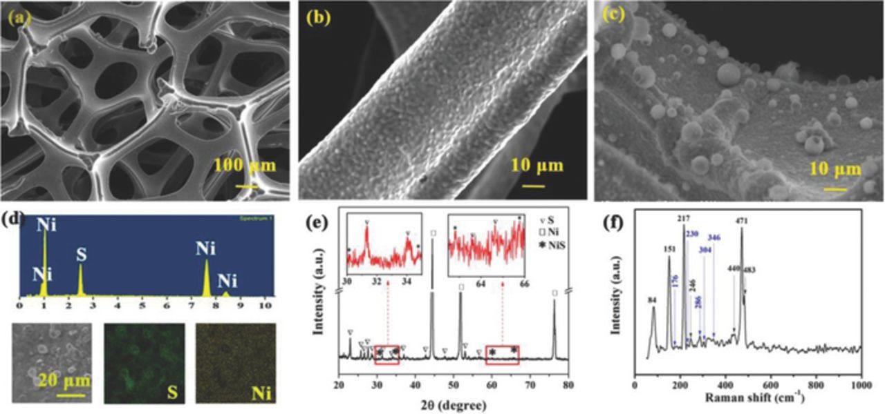
Figure 1. Scanning electron microscopy (SEM) images of nickel foam with (a) low and (b) high magnifications, and (c) SEM image, (d) energy-dispersive X-ray spectroscopy, (e) XRD pattern and (f) Raman spectrum of sulfur-nickel foam material.
To confirm the structure of sulfur on nickel foam, X-ray diffraction (XRD) and Raman spectrum were conducted (Fig. 1e-1f). Three significant diffraction peaks at 2θ = 44.4°, 51.7° and 76.4° correspond to nickel foam (JCPDS 4-850). All peaks of sulfur (JCPDS 08-0247) were indexed, and sulfur was detected from Raman spectrum. NiS can be identified by the diffraction peaks, as shown in the enlarged images in Fig. 1e, at 176, 230, 286, 304 and 346 cm−1 in Raman spectrum. Here, NiS may be formed through combining Ni2+ and S2−, which are produced by the oxidation of nickel with the high concentration of Cl− and disproportionation of thiosulfate, respectively. Thus, sulfur was obtained on nickel and the interface was sulfurized.
Fig. 2a displays the CV curves of sulfur-nickel foam cathode at a scan rate of 0.1 mV s−1. In the first cathodic scan, two weak and broad cathodic peaks at 2.35 V and 2.08 V are corresponding to the reduction of sulfur to long polysulfide chains and further to short polysulfide species, respectively. Here the cathodic peak (2.1 V) is nondetectable related to the electrical conductivity, the scan rate and the electrolyte system.4 The peaks located at 1.75 V and 1.27 V are related to a two-step reduction process (3NiS + 2Li → Ni3S2 + Li2S; and Ni3S2 + 4Li → Ni + 2Li2S).14–16 In the relevant anodic scan, anodic peaks at 2.45 V and 2.26 V are attributed to the oxidation process of Li2S/Li2S2 to sulfur. Other anodic peaks occur at 2.0 V and 1.40 V are due to the oxidation of Ni and Li2S to NiS, similar to that reported in previous work.15 There is no obvious change in the subsequent cathodic scan, except for a slight positive shift of the peaks at 2.35 V and 2.08 V, while the anodic peak at 2.45 V has a remarkable increase, indicating a certain polarization of the cathode.
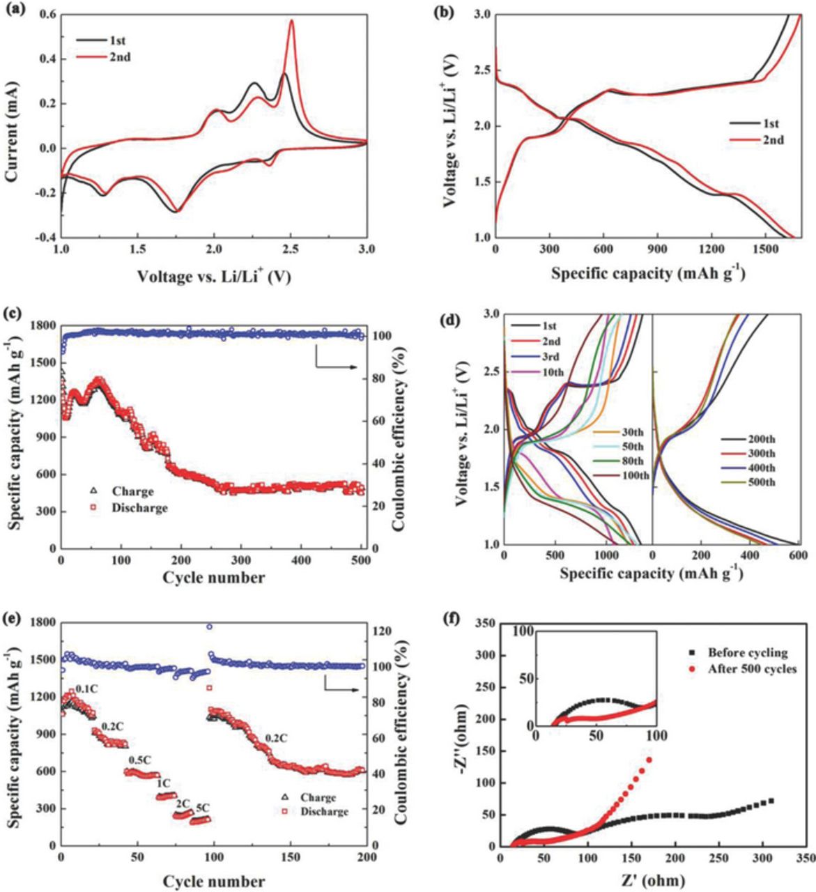
Figure 2. Electrochemical performance of sulfur-nickel foam cathode material: (a) CV curves at a scan rate of 0.1 mV s−1, (b) discharge/charge curves at 0.1 C, (c) the cycle performance and (d) corresponding discharge/charge curves at 0.5 C, (e) the rate capability at various rates and (f) EIS plots before cycling and after 500 cycles.
The discharge/charge curves of sulfur-nickel foam cathode at the rate of 0.1 C (1 C = 1675 mA g−1) are shown in Fig. 2b. The discharge plateaus at 2.38 V, 2.07 V, 1.82 V and 1.35 V followed by sloping potential ranges, namely 2.35–2.07 V, 2.05–1.82 V and 1.82–1.35 V, respectively, are consistent with the cathodic peaks in CV curves (Fig 2a). Similarly, the charge plateau at 1.92 V, 2.3 V and 2.4 V and a sloping potential range from 1.94 V to 2.3 V correspond to the anodic peaks. It is worth noting that, however, the discharge/charge curves are significantly different from the typical ones of sulfur observed in Li-S cells,4 because both sulfur and NiS are the active materials. The hysteretic slopes of the discharge potential may be due to the binding effect of nickel foam on sulfur,17–19 which causes good restraint of polysulfides within cathodes.3 An initial specific discharge capacity of 1340 mAh g−1 is obtained at the rate of 0.5 C, which retains at 493 mAh g−1 after 500 cycles (Fig. 2c). The overall coulombic efficiency is almost 100%. Thus, the sulfur-nickel foam cathode displays a good reversibility during a long term cycle.
To disclose the reason why the sulfur deposition on nickel foam can considerably improve the reversibility of the Li-S cells, the corresponding discharge/charge curves during the 500 cycle were analyzed (Fig. 2d). Only two charge/discharge plateaus at the 10th cycle that show typical plateaus of NiS are remarkably different from those at the first cycle, which implies that NiS becomes the main active material. From the 10th to 500th cycles, the plateaus at 2.07 V (Li2Sx, (8 ≤ x ≤ 3)→Li2S2/Li2S)4 become lower and shorter with a stable and sloping potential plateau range from 1.8 V to 1.3 V (NiS→Li2S)16 that delivers the main capacity, and NiS transfers to the main active material. Here it is noteworthy that the fast capacity decay observed from 60th to 200th cycles is due to the loss of electrical contact between active materials and nickel, which was caused by a huge volume change during Li+ intercalation/extraction.8
As shown in Fig. 2e, a discharge capacity of 1054 mAh g−1 is obtained at the rate of 0.1 C. At the rates of 0.2, 0.5, 1 and 2 C, the discharge capacities are 829, 567, 400 and 240 mAh g−1, respectively. At a high current rate of 5 C (8 A g−1), a capacity of 212 mAh g-1 is remained. However, the capacity of 610 mAh g−1 can be remained after 200 cycles when the current reduces from 5 C to 0.2 C, demonstrating a good abuse tolerance under various current densities. Also, the columbic efficiency is about 100%, except for the cycle of recovery from 5 C to 0.2 C. The overall rate property may benefit from the strong interface binding between sulfur and nickel and the three-dimensional porous structure of nickel foam.
EIS was carried out to investigate the internal resistance of the Li-S cells (see Fig. 2f). The semi-circle in the high and middle frequency ranges represents the charge transfer resistance (Rct), a resistance of the solid-electrolyte-interface layer of cell.20 Two depressed semi-circles are observed before cycling (inset of Fig. 2f), indicating the formation of a solid electrolyte interphase layer. The significant decrease of Rct is related to a better accessibility of the active material owing to the continuous immersion of electrolyte into the three-dimensional cathode.21 The less formation of non-conductive Li2S indicates the decrease of the capacity.20
The electrochemical evolution mechanism of sulfur-nickel foam cathode is schematically illustrated in Fig. 3. First, during the initial 10 cycles, the homogeneously dispersed sulfur particles are the main active material and the formed polysulfides are localized at cathode, keeping a high coulombic efficiency and capacity. Then, from 10 to 500 cycles, NiS plays a key role in the capacity, and more importantly, a small portion of Li2S is irreversible due to its poor electrical conductivity and the electrical contact loss between Li2S and nickel foam, leading to a gradual decrease of capacity. During the above process, the interconnected electrolyte-filled network and high electron transport pathways provided by the porous structure of nickel foam promise the efficient ion and charge transfer and reversible transformation of Li2S. Overall, combined the excellent interface binding between nickel foam and sulfur with the improved ion and electron conduction, the high stability and coulombic efficiency can be achieved in Li-S cells.
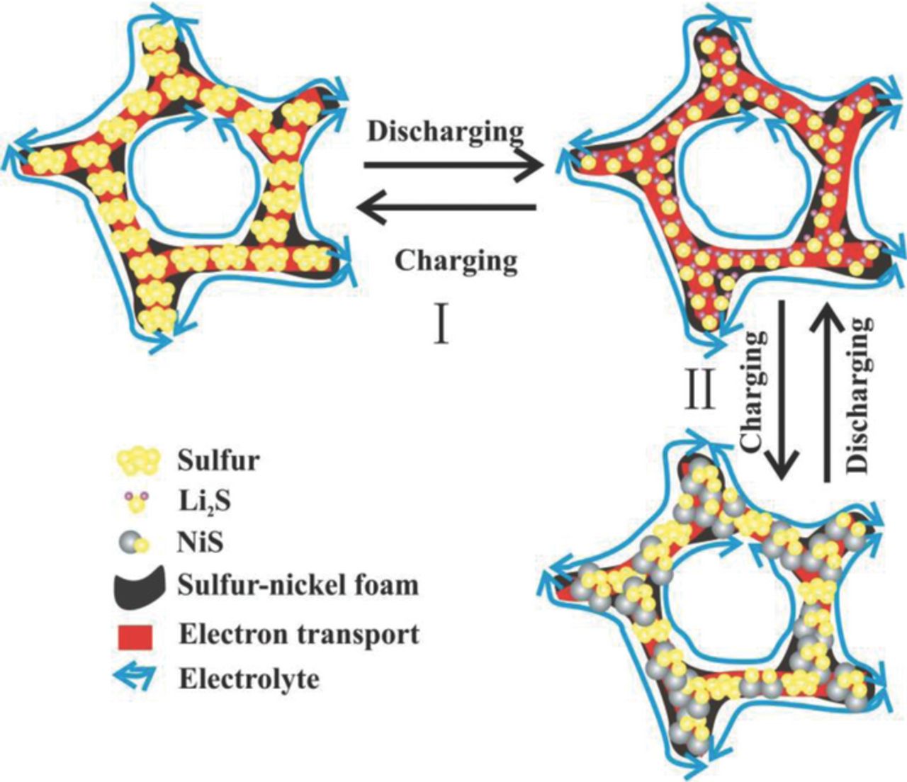
Figure 3. Schematic of the electrochemical evolution of sulfur-nickel foam cathode, where the symbols I and II represent the initial 10 cycles and 10 to 500 cycles.
Conclusions
In summary, we have demonstrated that a sulfur-nickel foam cathode can deliver a nearly 100% coulombic efficiency and a stable cycling during 500 cycles at the rate of 0.5 C. Furthermore, a recovered capacity of 610 mAh g−1 after various current rates is achieved. The nickel foam-sulfur cathode has the strong interface interaction between sulfur and nickel metal, which can localize sulfur in nickel foam and stabilize electrochemical reactions within the cathode region to form an inhibited shuttle. It is shown that such a cathode is very attractive for rechargeable batteries.
Acknowledgment
This work was supported by the National Natural Science Foundation of China (11372267 and 11102176), the Emerging Strategic Industries of Hunan Province (2012GK4075), the National High Technology Research and Development Program of China (863 Program) (2013AA032502), and the Graduate Innovation Program of Hunan Province (CX2013B258).