

Abstract
P2-type sodium transition metal oxide materials have a high theoretical capacity (∼170–210 mAh g−1) and exhibit high sodium-ion diffusion rates. In the present work, we report P2-type Sodium layered transition metal oxide Na0.67Mn0.5Fe0.5O2 material prepared by the simple solution combustion method followed by thermal treatment is studied as a promising cathode for Sodium-ion Batteries (SIBs). The formation of a pure hexagonal crystal system P2- Na0.67Mn0.5Fe0.5O2 with P63/mmc phase having plate-like morphology is confirmed. The electrochemical performance of the P2- Na0.67Mn0.5Fe0.5O2 as cathode for Sodium-ion Batteries shows an initial discharge capacity of ∼166 mAh g−1 with a moderate capacity retention of ∼111 mAh g−1 at a 0.1 C rate for 100 cycles. Further, the C rate performance of the material shows a reasonable capacity of >95 mAh g−1 at a 1 C rate. The slow decrease in performance during cycling of Na0.67Mn0.5Fe0.5O2 cathode is due to surface reconstruction, intragranular cracks, transition metal reduction and dissolution, and electrolyte decomposition which is evident from various surface studies. The P2-Na0.67Mn0.5Fe0.5O2 exhibits stable cycling and C-rate performance between 0.1C–1C which is superior to many of the literature results.
Export citation and abstract BibTeX RIS
The sodium-ion battery (SIB) has emerged as a potential energy storage device due to the economic efficiency resulting from the highly abundant and uniform geographical distribution of sodium resources in the Universe, ensuing in a reduction in cost concerning current Li-ion battery (LIBs)technology. 1,2 Especially, SIBs are getting more attention towards large-scale grid applications, where cost plays a major role in comparison to size. 3,4 Being a similar working principle of Li-ion batteries (LIBs), SIBs have advantageous in the transformation of synthetic strategies, and materials development methodologies utilized for LIBs to develop SIB electrochemistry. 5 However, the larger ionic radius (∼1.03 Å) and lower redox potential (−2.71 V vs SHE) of sodium in comparison to the Li (∼0.79 Å and −3.0 V vs SHE) result in severe challenges towards developing high-performance SIBs. 6,7
In recent times, several materials including layered transition metal oxides (Nax TMO2), polyanionic frameworks, and Prussian blue analogs have been investigated as potential cathodes for SIBs. 8–17 Transition metal layered oxides, Nax TMO2 (0 < x ≤ 1; TM = Fe, Cr, Co, Mn, Ni, V, Cu, and mixtures of them) are one of the most promising families of cathode materials due to their good cycling stability >200 cycles, and relatively high capacity of 120–210 mAh g−1. 18–25 Nax TMO2 layered oxides are mainly of two types, O3 and P2 according to the surrounding Na+ environment and the number of unique oxide layer stacking. 26,27 The P2-type materials show superior electrochemical performance (170–210 mAh g−1), exhibit high sodium-ion diffusion rates, and low phase changes (P2-O2) during the repeated sodiation/de-sodiation process as compared to those of O3-type materials (O3-P3-O3'-O3''). 23,28–31 Among various P2 type NaxTMO2, Na0.67Mn0.5Fe0.5O2 (NMF) is of great interest due to its high practical capacity (∼190 mAh g−1), and the economic feasibility, environmental friendliness of "Mn" and "Fe" based transition metal could play an important role for developing affordable high-performance SIBs. 32
Yabuuchi et al. reported the synthesis of Na0.67Mn0.5Fe0.5O2 cathode materials by solid-state method, which delivers an initial discharge capacity of 190 mAh g−1 in the potential range between 1.5 to 4.3 V at 12 mA g−1. 29 Similarly, Park et al. reported the synthesis of Na2/3[Fe1/2Mn1/2]O2 electrode material by chelating-assisted co-precipitation method. The material delivered an initial discharge capacity of 195 and 166 mAh g−1 at 0.1 C in the working potential window of 1.5–4.2 V, and 2.0–4.2 V, respectively. 21 Further, the hierarchical nanofibers of Na2/3[Fe1/2Mn1/2]O2 were prepared by the electrospinning method followed by step-wise calcination at various temperatures in a compressed air atmosphere. The Na2/3[Fe1/2Mn1/2]O2 nanofiber material could deliver a capacity of 195 mAh g−1 at 0.1 C in the potential window of 1.5–4.2 V. 33 Zhao et al. reported Mn-rich Na2/3Fe1/3Mn2/3O2 material synthesized by solid-state reaction, which could deliver 153 mAh/g discharge capacity after 40 cycles between 1.5 V and 4.3 V. 34 The electrochemical performance of NMF-based cathode materials is listed in Table I. Unfortunately, the cycling stability of this Na2/3[Fe1/2Mn1/2]O2 cathode is limited to 30–50 cycles. 33,35,36 The effective synthesis strategy with proper synthetic conditions could improve the material property towards better electrochemistry. In the present work, we report the synthesis of Na0.67Mn0.5Fe0.5O2 nanoplates using a solution combustion process followed by multistep calcination at various temperatures. Solution combustion is a simple, scalable self-sustained exothermic process, which promotes the formation of uniform nanoscale materials. In comparison to other synthesis methods, such as ball milling (need long milling time), co-precipitation (need to maintain temperature, pH, etc), this process is rapid and requires maintaining a fewer number of parameters. Further, the oxidant to fuel ratio, the final annealing temperature, and time could influence the particle size and morphology of the synthesized material. 37,38 Further, the reversible insertion/de-insertion of Na-ion into Na0.67Mn0.5Fe0.5O2 cathode is investigated in the potential range between 2.0–4.0 V unlike the literature reported cycling studies between 1.5 V and 4.3 V.
Table I. Comparison of Nax [FeyMn1−y]O2 cathode with the previously reported literature.
| Materials Composition | Synthesis Method | Calcination Time and Temperature | Working Potential Window | Current | Electrolytes | Capacity (initial Discharge) | Cycle Number | Capacity Retention (%) | References |
|---|---|---|---|---|---|---|---|---|---|
| Na2/3[Fe1/2Mn1/2]O2 | Solution-Combustion | 1000 °C for 6 h | 1.5–4.2 V | 0.1 C | 1 M NaPF6 in EC:PC | 210 mAh g−1 | 50 | 40 | 18 |
| Na2/3[Fe1/2Mn1/2]O2 | Co-precipitation | 850 °C for 12 hr. | 1.5–4.2 V | 0.1 C | 1 M NaPF6 in PC | 195 mAh g−1 | 30 | 82 | 21 |
| 2.0–4.2 V | 166 mAh g−1 | 94 | |||||||
| Na2/3[Fe1/2Mn1/2]O2 | Solid-state (Ball-mill) | 900 °C for 12 hr. | 1.5–4.3 V | 12 mA g−1 | 1 M NaClO4 in PC (fluorinated EC) | 190 mAh g−1 | 30 | 79 | 29 |
| Na2/3[Fe1/2Mn1/2]O2 | Electrospinning | 350 °C for 2 hr →500 °C for 2 hr →900 °C for 2 hr | 1.5–4.2 V | 0.1 C | 1 M NaClO4 in PC (with 2% FEC) | 195 mAh g−1 | 80 | 85 | 33 |
| Na2/3[Fe1/3Mn2/3]O2 | Solid-state (Ball-mill) | 900 °C for 12 h | 1.5–4.3 V | 12 mA g−1 | 1 M NaPF6 in PC | 193 mAh g−1 | 40 | 80 | 34 |
| Na2/3[Fe2/3Mn1/3]O2 | Solid-state (Ball-mill) | 1000 °C for 12 hr | 1.5–4.2 V | 0.1 C | 0.5 M NaPF6 in EC:DMC | 151 mAh g−1 | 15 | 81 | 35 |
| Na2/3 [Fe1/2 Mn1/2 ]O2 | Solution-Combustion | 800 °C for 4 h → 900 °C for 6 h | 2.0–4.0 V | 0.1 C | 1 M NaClO4 in EC: DEC | 166 mAh g−1 | 100 | 67 | This work |
Experimental
Materials synthesis
The synthesis of P2-type Na0.67Mn0.5Fe0.5O2 was carried out using a simple solution combustion process. In this process, a stoichiometric mixture of NaNO3 (99%), Mn(NO3)2.4H2O, Fe(NO3)2.6H2O is used as oxidants and glycine as fuel. The oxidant to fuel ratio was kept 1:1. All the chemicals used in the present work are of analytical grade, procured from Sigma-Aldrich, and used as received. The metal nitrates and glycine were dissolved in an appropriate amount of deionized water in a beaker, subsequently heated at 100 °C till a viscous slurry was formed. Then 2 ml of concentrated nitric acid was added, dried for some time, and placed in a preheated furnace at 400 °C for few minutes for auto-ignition to form amorphous Na0.67Mn0.5Fe0.5O2. Further, the as-prepared sample was kept at 400 °C for 30 min for the complete removal of organics impurities followed by annealing at 800 °C for 4 h and 900 °C for 6 h at a heating rate of 5 °C min−1 in an alumina crucible in the presence of air.
Materials characterizations
The phase structural analysis of the sample was carried out using a powder X-ray diffraction (PXRD) study. The PXRD measurements were performed by using an X'Pert Pro diffractometer (The Netherlands) (reflection θ–θ geometry, Cu Kλ radiation (λ = 1.5406 Å), receiving slit of 0.2 mm, scintillation counter, 30 mA, 40 KV). The diffraction data were collected at 0.03 step widths over a 2θ range from 10° to 80°. The structural parameters obtained from PXRD were refined by Rietveld refinement analysis using the Full Prof Suite program. The microstructure analysis of the sample was carried out using high-resolution transmission electron microscopy (HRTEM, Jeol JEM-2100 FX). The structural characterization of the material was further carried out using Raman spectroscopy analysis using a micro Raman spectrometer HR800 (Jobin Yovn Horiba, France), with He-Ne laser (excitation line 632.8 nm) and a microscope objective (50×, Olympus Mplan, 0.4 mm working, numerical aperture 0.75 in backscattering configuration). The morphology and elemental composition of the material were obtained by using scanning electron microscopy (ZEISS FESEM, Germany), and energy dispersive X-ray analysis (EDAX, Oxford Instruments), and detailed surface analysis and chemical composition samples were carried out using X-ray photoelectron spectroscopy (Thermo Fischer Scientific Pvt. Ltd. UK) respectively.
Electrochemical measurements
The electrochemical characterizations of the material were carried out by fabricating coin-type Na-ion half cells (CR2023) with sodium metal (Alfa Aesar) as the counter electrode, 1.0 M NaClO4 in 1:1 EC (ethylene carbonate), and DEC (Diethyl carbonate) as the electrolyte, and the glass fiber GF/D (Whatman paper) as the separator. The composite slurry for electrode fabrication was prepared by mixing the active material with the conducting additive carbon black and poly (vinylidene fluoride) (PVDF) (Kureha, Japan) binder in N-methyl pyrrolidinone (NMP) (Sigma Aldrich) in a mass ratio of 80:10:10. The composite slurry was uniformly coated on Al foil, dried overnight at 100 °C in a vacuum oven, and punched into electrodes of 10 mm diameter. The mass of active materials on the electrode disks was maintained to be ∼5 mg cm−2. Further, the Na-ion half cells were fabricated in a glove box (MBraun, Germany) filled with Ar gas having O2 and H2O levels of <0.1 ppm. The open-circuit voltage of the cell after the assembly of cells was about 2.7 V. The cells were given rest for about 24 h before electrochemical tests. The electrochemical performances of half cells were measured by using cyclic voltammetry, galvanostatic charge-discharge, and electrochemical impedance spectroscopy. All the electrochemical measurements were performed at room temp 25 ± 2 °C by using a Solartron cell test system consists of 1470E multi-channel potentiostat and multiple 1455 A series frequency response analyzers (FRAs) and the obtained data were analyzed using Corrware and ZPlot software from Scribner Associates. Charge-discharge cycling was carried out in the potential range between 2.0 V and 4.0 V using the CC (constant current) protocol. The first charge was carried out from the OCV of the cell. The impedance measurements were carried out in a frequency range between 1 MHz and 10 mHz.
Results and Discussion
The X-ray diffraction patterns of P2-type Na0.67Mn0.5Fe0.5O2 material along with the corresponding Rietveld refinement are shown in Fig. 1a. All the diffraction peaks obtained at 2θ = 15.8°, 31.9°, 35.4°, 38.9°, 43.0°, 48.3°, 61.6°, 63.6°, 66.1o, , 72.8°, 75.6°, and 77.8° are indexed to (002), (004), (100), (102), (103), (104), (106), (110), (112), (114), (201), and (108) planes. The structural refinement studies performed on the powder diffraction pattern of P2- Na0.67Mn0.5Fe0.5O2 confirm hexagonal P63/mmc space group with lattice parameter of a = b = 2.919034 Å; c = 11.289365 Å. In addition to PXRD, Raman spectroscopy was employed to find out the crystal chemistry of layered transition metal oxides for the structural analysis of the material. 39 All the Raman active modes of P2-Na0.67Fe0.5Mn0.5O2, such as A1g (666 cm−1), E1g (193 cm−1), E2g (480, 520, and 622 cm−1) can be identified from the obtained spectrum, as shown in Fig. 1b. The A1g and Eg are corresponding to the out-of-plane M-O stretching and in-plane O-M-O bending, respectively. 40
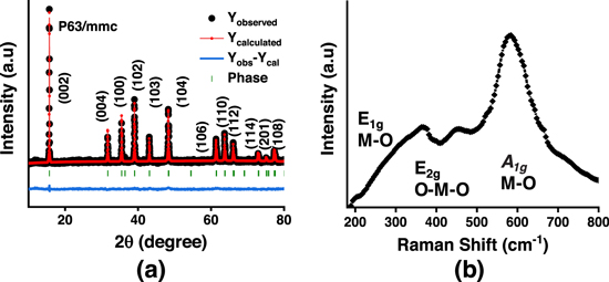
Figure 1. (a) PXRD and Rietveld refinement of Na0.67Mn0.5Fe0.5O2 sample. (b) Raman spectra of Na0.67Mn0.5Fe0.5O2.
Download figure:
Standard image High-resolution imageThe surface morphology and elemental composition of the as-prepared NMF sample were carried out using FESEM and EDS analyses (Figs. 2a–2c and 3). FESEM image of the well crystalline NMF sample shows the agglomeration of primary plates (∼1–2 μm) to form secondary particles (∼6–10 μm) of Na0.67Mn0.5Fe0.5O2 material, as shown in Figs. 2a–2c. As the morphology and particle size of the cathode material is the key to achieving good electrochemical performance for sodium-ion batteries, the synthesized material with a regular and homogeneous distribution of nanosized particles may have more advantages towards the electrochemical performance. Further, the microstructure analysis of the layered P2-type Na0.67Mn0.5Fe0.5O2 material carried out using HRTEM analysis, as shown in Figs. 2d–2f. The HRTEM image clearly shows the flaky-bundle morphology of the material with sharp edges having a particle size of around 2 μm (Fig. 2d). The crystalline nature of the sample was confirmed from the obtained lattice fringes and selected area electron diffraction (SAED) patterns (Figs. 2e–2f). The d spacing value of material obtained from the lattice fringes is 0.280 nm corresponds to the (004) plane which is in good agreement with the obtained XRD pattern (Fig. 1a). The SAED patterns (Fig. 2f) of the material are also matching perfectly with the XRD pattern as shown in Fig. 1a and confirm the formation of a single-phase hexagonal structure of the NMF sample. The elemental composition of the synthesized material was obtained from the EDS analysis and the corresponding elemental mapping results are given in Fig. 3.
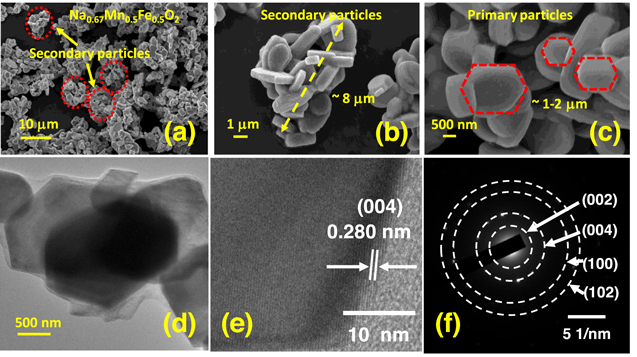
Figure 2. (a)–(c) FESEM images of the layered Na0.67Mn0.5Fe0.5O2 at various magnification; (d) TEM image shows the plate-like morphology with layer, (e) HRTEM image shows lattice fringes confirming the high crystallinity of the material, (f) SAED pattern shows single-phase layered structure of Na0.67Mn0.5Fe0.5O2.
Download figure:
Standard image High-resolution image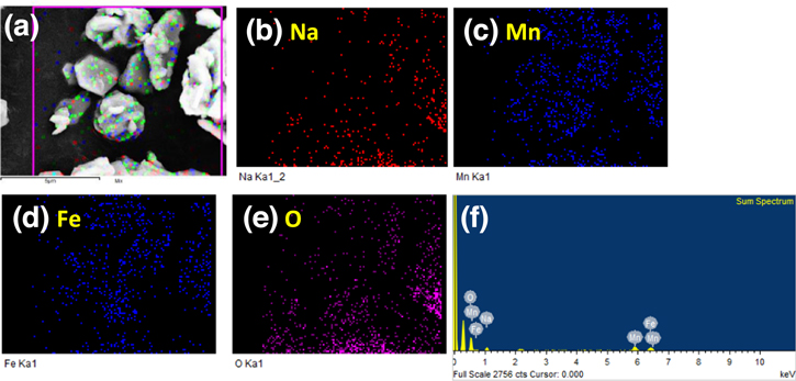
Figure 3. Elemental mapping of the layered Na0.67Mn0.5Fe0.5O2 material: (a) analysis area, and corresponding elements (b) Na, (c) Mn, (d) Fe, and (e) O, and (f) EDS mapping of the layered Na0.67Mn0.5Fe0.5O2 material.
Download figure:
Standard image High-resolution imageThe electrochemical changes (redox reactions) in terms of Na-ion storage behavior and the influence of Mn/Fe were studied using the cyclic voltammetry responses of NMF material recorded in the potential range between 2.0–4.0 V (vs Na/ Na+) at a scan rate of 0.05 mV s−1. The obtained voltammograms in Fig. 4a shows typical peaks associated with the electrochemical sodiation/de-sodiation processes. Two pairs of redox couples are observed, which are consistent with the working plateaus found in the voltage profiles. At low voltage range, the material exhibits a reversible redox process at about 2.03/2.25 V vs Na/Na+, i.e. higher sodium contents, due to the Mn3+/Mn4+ redox process and corresponding structural rearrangement of the layer because Mn4+ shows no electrochemical activity above 2.7 V in the layered oxide. 19,32,41 Additionally, the redox peaks at 3.8/4.0 V is due to the Fe3+/Fe4+ redox reactions. The redox activities of transition metal ions allow sodiation and de-sodiation into the host structure. On subjecting to repeated cycling, the intensity of current responses decreases a little, and the peak positions are slightly shifted initially and stabilize during later cycles. The obtained cyclic voltammetry results clearly show the potential of the Na0.67Mn0.5Fe0.5O2 material prepared by solution combustion as a cathode material for Na-ion batteries.
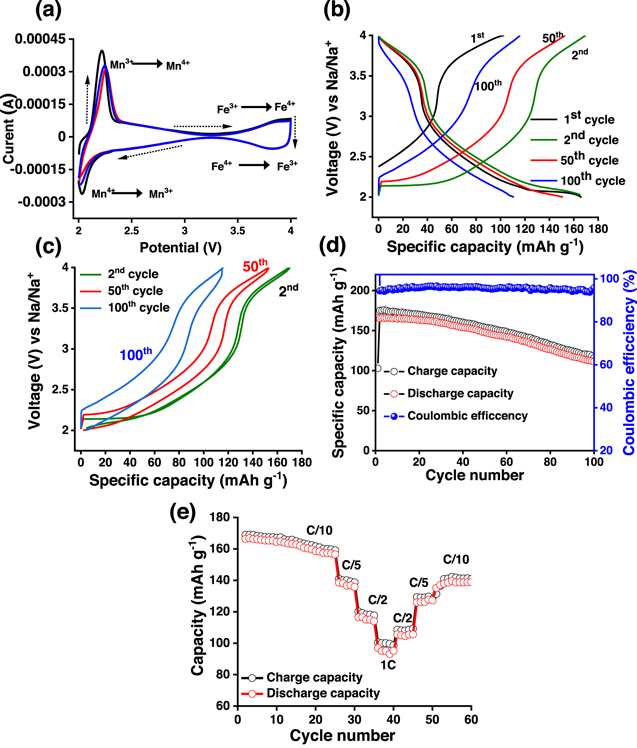
Figure 4. (a) Cyclic voltammograms of Na0.67Mn0.5Fe0.5O2 electrode vs Na/Na+ during the initial three cycles at a scan rate of 0.05 mV s−1 in the potential range between 2.0 and 4.0 V; (b) Charge-discharge voltage profiles during 1st, 2nd, 50th, and 100th cycles, (c) Hysteresis plot during 2nd, 50th, and 100th cycle, (d) Cycle stability and variation in coulombic efficiency at C/10 rate for 100 cycles, and (e) C-rate performance of Na0.67Mn0.5Fe0.5O2 composite electrode at various rates as shown in the figure.
Download figure:
Standard image High-resolution imageThe galvanostatic charge-discharge curves of the NMF material during the 1st, 2nd, 50th, and 100th cycles are shown in Fig. 4b. The obtained charge-discharge curves show good reversible capacity and smooth voltage profiles. The charge-discharge voltage plateaus are very similar to the Fe and Mn redox reactions explained in CV curves to Fig. 4a. This particular P2 type cathode shows two different discharge regions, 2–2.8 V and 3.5–4.0 V (confirmed by CV plots in Fig. 4a as well ). In the pristine material (before cycling), the majority of the "Mn" is present as Mn4+, to maintain the charge neutrality. Thus, during the 1st charging, full charge capacity was not observed (observed capacity is 102 mAh g−1). However, during discharge, the reduction of Mn4+ to Mn3+ is resulting in a discharge capacity of 166 mAh g−1. Besides, the lower region capacity (2–2.8 V) is contributing around 63%–68% of the capacity, suggesting better electrochemical activity of Mn-transition metal site in Na0.67Mn0.5Fe0.5O2 cathode. 42,43 Further, when we compared the charging capacity value corresponding to the 3.5–4.0 V region, during the 50th and 100th cycle, the value seems to be similar (36–40 mAh g−1) for Na0.67Mn0.5Fe0.5O2 cathode. This signifies the degradation of electrochemical performance of Na0.67Mn0.5Fe0.5O2 cathode is mostly originating from the Mn-dissolution, which is discussed later. This could impact the charge-discharge voltage profile at different cycling states.
Further, the round trip (hysteresis plot) charge-discharge profile of P2-type Na0.67Mn0.5Fe0.5O2 cathode, during 2nd, 50th, and 100th cycles is shown in Fig. 4c. The hysteresis plot shows a slight increase of round trip voltage difference from 0.01 V (during the 2n d cycle) to 0.16 V during the 50th cycle to 0.35 V in the 100th cycle (Fig. 4c). Also, there is a slight change in average voltage observed during cycling. The cycling studies of Na0.67Mn0.5Fe0.5O2 material at the C/10 rate within the potential range of 2.0–4.0 V for 100 cycles are shown in Fig. 4d. The material shows an initial discharge capacity of ∼166 mAh g−1 and was found to be decreased to ∼150 mAh g−1 at the 50th cycle. Further, the material was found to show a capacity of 111 mAh g−1 at the end of the 100th cycle. However, the coulombic efficiency of the material remains between 96%–94% throughout the cycle-life. The C-rate performance of the material at different rates such as C/10, C/5, C/2, and 1 C are studied and represented in Fig. 4e show that the material delivers a capacity of 166, 138, and 117 mAh g−1 at a rate of C/10, C/5, and C/2, respectively. Further, a capacity of about 95 mAh g−1 is observed when the cell was discharged at a 1 C rate (Fig. 4e). After C rate performance when the cells are cycled back to the C/10 rate, there is a loss of capacity w.r.t. to C/10 rate of initial. The slow decrease in performance after C rate cycling of Na0.67Mn0.5Fe0.5O2 cathode is due to phase transformation, transition metal reduction and dissolution, and electrolyte decomposition which is discussed later. The cycling performance and specific capacity of this work are superior to many of the literature results shown in Table I.
The decrease in capacity of the material upon cycling is attributed to the structural instability of the material and it was further confirmed from the (dQ/dV) plots. The (dQ/dV) plots of the material at 1st, 50th, and 100th cycles are shown in Fig. 5a. The (dQ/dV) plots show the degradation of the Mn-redox peak during cycling suggesting the high manganese dissolution while cycling. To understand the polarization effects during cycling, the electrochemical impedance spectroscopy (EIS) measurements are carried out before cycling, after the 1st cycle, and after 100 cycles. The corresponding Nyquist plots of the NMF sample measured at full discharge condition (up to 2.0 V) are shown in Fig. 5b. All the plots are consisting of two semi-circles in the high to mid-frequency region and mid to low frequency domain. Equivalent circuit Ro(R1Q)(R2Q) is used for fitting these Nyquist plots. Where Ro is the combined solution (series) resistance; R1 is the surface layer resistance and R2 is the charge-transfer resistance; Q1 and Q2 are the constant phase element associated with surface film capacitance and double-layer capacitance, respectively. 44–46 The solution resistances (Ro) and R2 values are around 8, and 1744 Ω cm2, respectively, before cycling. The value of Ro and R2 after 1st and 100th are 10.7, 12.6, and 1069, 3050 Ω cm2, respectively. The R1 and R2 value is decreased after 1st cycles, suggesting the lower resistance at the electrode-electrolyte interface, due to activation of NMF electrode material and better wettability of the electrode at the same time. However, the diameter is increased after 100 cycles, which suggests an increase in charge transfer resistance and the slow degradation of the electrode material due to the formation of an undesired insulating surface layer on the electrode material.
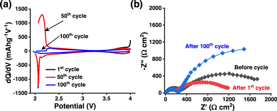
Figure 5. (a) dQ/dV plots Na0.67Mn0.5Fe0.5O2 of during 1st, 50th and 100th charge-discharge cycles. (b) Nyquist plots of Na0.67Mn0.5Fe0.5O2 electrode at different cycles.
Download figure:
Standard image High-resolution imageFurther, to identify the morphological and structural changes in the electrode during cycling, FESEM, and XRD of the electrode after 100 cycles are evaluated. After 100 cycles, the cell was disassembled, followed by washing the electrode in dimethyl carbonate (DMC) solvents to remove the presence of NaClO4 salt followed by drying under vacuum overnight. The FESEM images of the cycled electrode at various magnifications are shown in Figs. 6a–6d. It is observed that the morphology of the Na0.67Mn0.5Fe0.5O2 materials in the cycled electrode (Fig. 6b) remains similar without degradation (inset: Fig. 6b). The presence of surface cracks and surface reconstruction is evident from the FESEM image (Figs. 6c–6d). This could be a result of the electrolytic degradation at the cathode surface and Mn-dissolution, resulting from the undesirable reactions at the electrode-electrolyte interface. 47,48 The X-ray diffraction pattern suggests structural changes in the Na0.67Mn0.5Fe0.5O2 material with cycling. As shown in Figs. 6e–6f, the intensity of XRD peaks after 100 cycles become weaker. Besides, the peak positioned at 72.8 degrees (2θ value) is disappeared and one new peak at 26.5 degrees seems to appear after cycling. Further, the peaks positioned at 15.8, and 31.9 degrees are shifted to a lower angle. All these phenomena are dictating the evolution of new phases in the materials. It has been established that Mn3+ is a Jahn-Teller distorted ion, 49 which promotes the disproportionate reaction of Mn3+ to Mn4+ and Mn2+, and Mn2+ is prone to dissolute in the ester-based electrolytic medium, 50–52 which could be further responsible for the slow degradation in electrochemical performance of these electrode materials. The negative shift of XRD peaks demonstrates that the new phase has a larger interlayer distance, because of transition interlayer shrinkage upon cycling, favoring the dissolution of Mn2+. 53
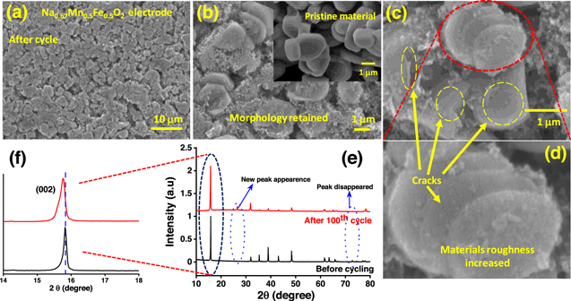
Figure 6. (a)–(d) FESEM images of cycled Na0.67Mn0.5Fe0.5O2 electrode at various magnifications (Fig. 6(b) inset: scale pristine Na0.67Mn0.5Fe0.5O2 material); (e)–(f) X-ray diffraction pattern of Na0.67Mn0.5Fe0.5O2 electrode before and after cycling.
Download figure:
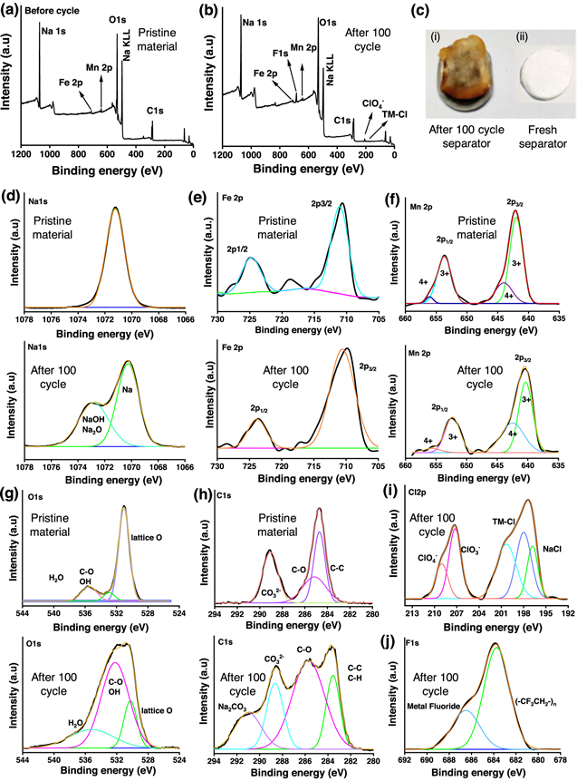
Standard image High-resolution imageTo study the interfacial surface changes taking place while operating P2-type Na0.67Mn0.5Fe0.5O2 cathode materials, XPS studies were performed for pristine and cycled electrode materials, as shown in Figs. 7a–7b. In the earlier reports, the performance degradation of O3-NaNi1/3Fe1/3Mn1/3O2 cathode operating between 2.0–4.0 V is attributed to several factors, such as surface reconstruction, intragranular cracks, transition metal reduction and dissolution, and electrolyte decomposition. 54,55 As mentioned earlier, the possibility of oxygen loss associated with surface reconstruction may further promote the transition metal dissolution and reduction. 54 Besides, the continuous capacity fading in P3 type Na2/3Mg1/3Mn2/3O2 cathode is attributed to the gradual degradation of Mn3+/Mn4+ and O2−/O− redox behavior. 56 Thus, with prolonged cycling the possibility of surface oxygen evolution enhances, resulting in structural deterioration and electrolyte oxidation. 54,56–58 The transition metal dissolution is further spotted on the cycled separator (Fig. 7c). Na1s spectra of the cycled electrode are indicating the formation of NaOH/Na2O species with cycling (Fig. 7d). Fe2p (Fig. 7e) and Mn2p (Fig. 7f) spectra of pristine and cycled material showing similar nature with the partial shift towards lower binding energy in case cycled material, suggesting the partial reduction of transition metal oxide. Further, the presence of metal chloride/fluoride (Figs. 7i and 7j) on the cycled electrode predicts the possibility of the formation of electrolytic decomposition products such as metal chloride/fluoride on the surface of the cathode material. 59 Besides the presence of C–O/C=O based organic species, and Na2CO3 group from O1s and C1s spectra (Figs. 7g and 7h) at cycled electrode materials signify the electrolytic reaction products and surface reconstruction that takes place at the cathode-electrolyte interphase. 60,61 The chemical environment at the cathode-electrolyte interphase could influence the electrochemical performance of Na0.67Mn0.5Fe0.5O2 cathode material. Thus, the careful designing of Na-ion battery cathode by reducing the transition metal dissolution, electrolytic decomposition, and structural instability is desired for the long-term operation of Na-ion batteries.
Figure 7. X-ray Photoelectron spectroscopy of pristine and cycled Na0.67Mn0.5Fe0.5O2 electrode materials. (a) Survey scan of the pristine material, (b) survey scan of the cycled electrode, (c) Photograph of cycled and fresh separator, (d) Na1s, (e) Fe2p, (f) Mn2p, (g) O1s, (h) C1s (i) Cl2p, (j) F1s spectra.
Download figure:
Standard image High-resolution image
Conclusions
P2-type Na0.67Mn0.5Fe0.5O2 having platelet-like morphologies have been synthesized through a simple solution combustion method followed by multistep thermal treatment and studied as a cathode material for Na-ion storage. The cathode material consists of secondary particles of 6–10 μm having primary plate-like morphologies of ∼1–2 μm. The material showed an initial discharge capacity of ∼166 mAh g−1 with good capacity retention even after 50 cycles (90% at the 50th cycle). The material retained a specific capacity of 111 mAh g−1 after 100 cycles. The capacity loss could be due to an increase in Na-ion diffusion resistance and Mn-dissolution upon cycling. The presence of surface cracks and surface reconstruction is observed from the FESEM image. This could be a result of the electrolytic degradation/reaction at the cathode surface and Mn-dissolution, resulting from the undesirable side reactions at the electrode-electrolyte interface. Besides, XPS of the cycled electrode materials signifies the electrolytic reaction products such as metal halides, C–O/C=O based organic species, and Na2CO3 that slowly grows on the surface of the cathode. This leads to surface reconstruction at the cathode-electrolyte interphase. The chemical environment at the cathode-electrolyte interphase could influence the electrochemical performance of Na0.67Mn0.5Fe0.5O2 cathode material. In comparison to the earlier reports, herein we have extended the cycling and C-rate performance studies and exhibited the solution combustion method as a versatile route for the preparation of Na0.67Mn0.5Fe0.5O2 cathode materials for SIB applications.
Acknowledgments
VKK acknowledges UGC-NET, Govt. of India. SKM acknowledges Research Center Imarat (DRDO), Hyderabad under grant no. RCI/CAAT/8151/CARS-358 for financial support. We thank Shri. K. Rambabu, Dr. T. S. Balasubramanian, Dr Shalabh Mehta, Shri D. S. Reddy of RCI (DRDO), and Dr. Pratyay Basak of IICT, Hyderabad for various suggestions.