
Abstract
Surface Sb/Ni and Sn/Ni alloys were found to efficiently minimize the negative effects of sulfur on the performance of Ni/zirconia anode-supported solid oxide fuel cells (SOFC). Prior to operating on fuel gas containing low concentrations of H2S, the nickel/ zirconia anodes were briefly exposed to antimony or tin vapor, which only slightly affected the SOFC performance. During the subsequent exposures to 1 and 5 parts per million H2S, increases in anodic polarization losses were minimal compared to those observed for the standard nickel/zirconia anodes. Post-test x-ray photoelectron spectroscopy analyses showed that Sb and Sn tended to segregate to the surface of Ni particles, and further confirmed a significant reduction of adsorbed sulfur on the Ni surface in Ni–Sn and Ni–Sb samples compared to the Ni. The effect may be the result of weaker sulfur adsorption on bimetallic surfaces, adsorption site competition between sulfur and Sb or Sn on Ni, or other factors. The use of dilute binary alloys of Ni–Sb or Ni–Sn in the place of Ni, or brief exposure to Sb or Sn vapor, may be an effective means to counteract the effects of sulfur poisoning in SOFC anodes and Ni catalysts. Other advantages, including the suppression of coking, are also expected.
Export citation and abstract BibTeX RIS
Deleterious effects of hydrogen sulfide, an ubiquitous impurity in synthesis gas derived from coal and biomass, on the performance of a Ni-based solid oxide fuel cell (SOFC) anode have been extensively investigated.1–7 It has been well established that Ni is very sensitive to the presence of sulfur even in low amounts of H2S, 0.1–1 parts per million (ppm). Rather than form solid phases with Ni at these concentrations, hydrogen sulfide affects performance through chemisorption onto Ni surfaces: anode performance losses have been directly related to the sulfur coverage of nickel.6 The Ni-based anode is able to fully recover when no sulfur is present in the feed gas after exposures to H2S concentrations below ∼2 ppm4, 8 and the recovery becomes much slower after exposures to higher H2S concentrations.9 Improvement in nickel/yttrium-stabilized zirconia (Ni/YSZ) sulfur tolerance is desired as an alternative to thorough sulfur cleanup to mitigate the potential impact of H2S exposure.
To improve the sulfur tolerance of SOFCs, alternative anode compositions have been proposed. Copper/ceria/zirconia anodes were reported to be stable in fuel gases containing up to 450 ppm H2S.10 At higher H2S concentrations, anode deactivation accompanied by the formation of Ce2O2S was reported at 800°C.10 Other anode compositions showing good sulfur tolerance include a lanthanum-doped strontium titanate,11 titanate/ceria composits,12 Pd-impregnated titanate/cerate composition,13 lanthanum molybdate,14 gold/molybdenum disulfide,15 Ni/YSZ modified with niobia,16 and lanthanum vanadium oxide.17, 18 For considerations including cost, processability, and stability, minor modifications to the widely used Ni/YSZ anode may be preferred to more exotic compositions and forms.
In this study, the addition of minor amounts of tin and antimony to the nickel/yttrium-stabilized zirconia (YSZ) anode by pre-expositing to the metal vapor were assessed as a means of suppressing nickel– sulfur interactions. Both Sb and Sn are well-known passivating agents for nickel catalysts,19–26 through the formation of solid solutions or through the formation of surface alloys. The formation of similar bimetallics has been shown to be useful for controlling or preventing sulfur poisoning of Pt catalysts27 as well as in suppressing coke formation on Ni.28–31
Experimental
Button cell configurations
Cell tests were conducted using Ni/YSZ anode-supported button cells with an active area of 2 cm2. Cells were fabricated as described previously.32 The Ni/YSZ support was approximately 0.9 mm thick and was comprised of a Ni/YSZ bulk layer with a 40/60 vol % solids ratio and approximately 30 vol % porosity, and an approximately 5-µm-thick active Ni/YSZ electrode layer with 50/50 solids vol % Ni/YSZ. The electrolyte was 8 mol % YSZ, approximately 4.5 μm in thickness. A 2.8 µm-thick samaria-doped ceria barrier layer was applied to the presintered at 1375°C anode-electrolyte structure by screen printing followed by sintering at 1200°C. A 20 µm-thick (La0.80Sr0.20)0.98MnO3 (LSM-20) cathode was applied in the same manner and sintered at 1100°C for 2 h. A NiO paste grid was screen-printed onto the anode to serve as the anode current collector and fired at the time as the ceria layer together with electrical leads pressed against the anode. The cathode current collector was Ag foil grid impregnated with Ag paste and sintered in situ during seal curing. Cells were sealed to alumina test fixtures with a barium aluminosilicate glass by heating to 800°C in air.
Cell testing
Cell tests were performed at 0.7 V at 800°C. Fuel gas was hydrogen buffered with 10% CO2. Prior Sb, Sn, and H2S additions cells were preconditioned to obtain stable baseline characteristics. All experiments were performed at low fuel utilizations <10%. Tin or antimony vapor was added using a stable thermal evaporation source as described previously.33 A small alumina reservoir was filled with Sb or SnCl2 powders and inserted inside the alumina tube to which a fuel cell was attached. The reservoir temperature was constantly monitored by a thermocouple attached to the reservoir bottom and protected with a glass coating from any undesired interactions with Sb or Sn. The measured temperature of the reservoir was used to calculate the total Sb and Sn vapor pressure in the gas using a HSC Chemistry, v. 6.12.34 In the beginning of all tests, the reservoir was held at temperatures below 90°C until the baseline cell performance on clean fuel gas was obtained. To add Sb or Sn, the position of the reservoir was changed by elevating it into the hot zone and held for 1 h, then lowered down to temperatures below 90°C to terminate the Sb or Sn dosage. H2S was added from a cylinder using a calibrated mass-flow controller and was injected near the anode bypassing the Sb and Sn reservoirs.
The electrochemical cell characteristics were monitored using Arbin potentiostat and a Solartron 1260/1287 electrochemistry system. The cathode was supplied with pure oxygen from a pressure swing adsorption unit to minimize the cathodic polarization contribution.
Post-test analyses
Following termination of electrochemical tests, cells were cooled down to room temperature in dry hydrogen without H2S and analyzed by scanning electron microscopy with energy dispersive spectrometry (SEM/EDS) and by high energy resolution x-ray photoelectron spectroscopy (XPS) to evaluate whether anode interactions with Sn, Sb, and S led to the alteration phase or surface adsorption layer formation.
Thermochemical calculations
Phase boundaries for the formation of Ni–Sb and Ni–Sn solid solutions versus temperature were calculated using HSC Chemistry 6.12.34
Results
Effect of Sb on H2S poisoning
During the addition of 1 ppm Sb to the fuel gas, the current density measured at a constant voltage of 0.7 V almost immediately decreased, indicating that minor anode poisoning by Sb took place. Consequently, the area-specific resistance (ASR) of the cell slightly increased (Fig. 1). This is consistent with our earlier findings reporting a rapid but minor current drop observed on the anode-supported cells in the presence of small concentrations of Sb.33 Following Sb exposure, the anode was allowed to operate in hydrogen for up to 5 h. During this period, a slight improvement in the cell performance was noticed that could be indicative of Sb diffusion into Ni bulk or to Sb desorption. When 1 ppm of H2S was added to buffered hydrogen, yet another cell performance drop (an ASR increase) due to sulfur poisoning was observed. The response to 1 ppm H2S was larger than that to 1 ppm Sb, but still by a factor of 3–4 less than the performance loss of the standard Ni/YSZ anode (Fig. 1). Electrochemical impedance spectra were obtained at the same bias and are illustrated in Fig. 2. As seen in Fig. 2b, a cell resistance increase in the presence of either Sb or H2S was due to an increase in the electrodic resistance, as evidenced by an increase in the low frequency intercept with the x axis. The ohmic resistance, i.e., a high frequency intercept with the x axis, did not change during this test.
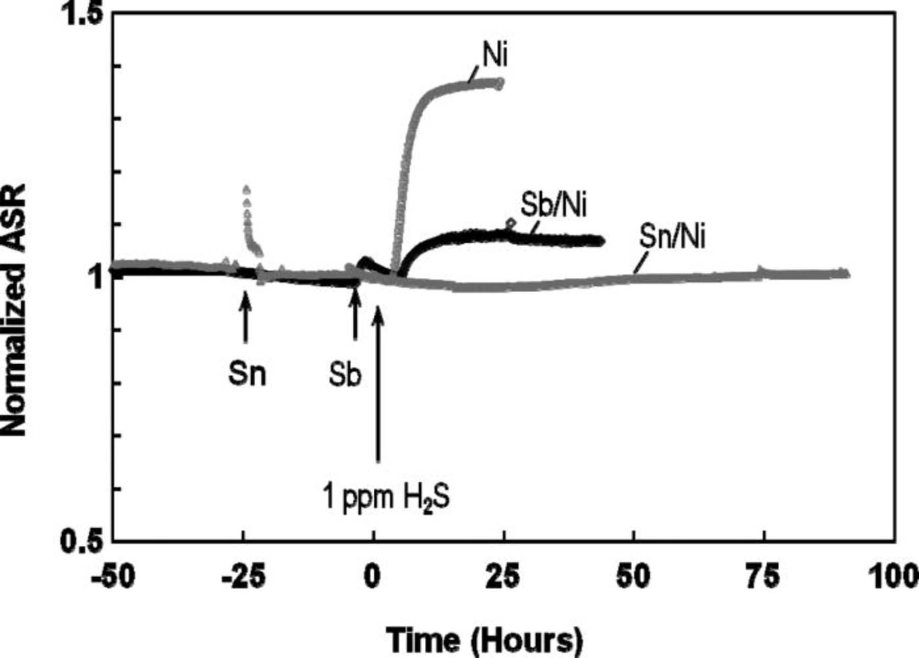
Figure 1. Change in area specific resistances (ASR) of cells with a standard Ni/YSZ anode (Ni) and anodes pretreated with 1 ppm Sb (Sb/Ni) and 10 ppm Sn (Sn/Ni) in the presence of 1 ppm H2S in moist hydrogen. All tests were performed at a constant voltage of 0.7 V at 800°C. The time when H2S was added was moved to the origin.
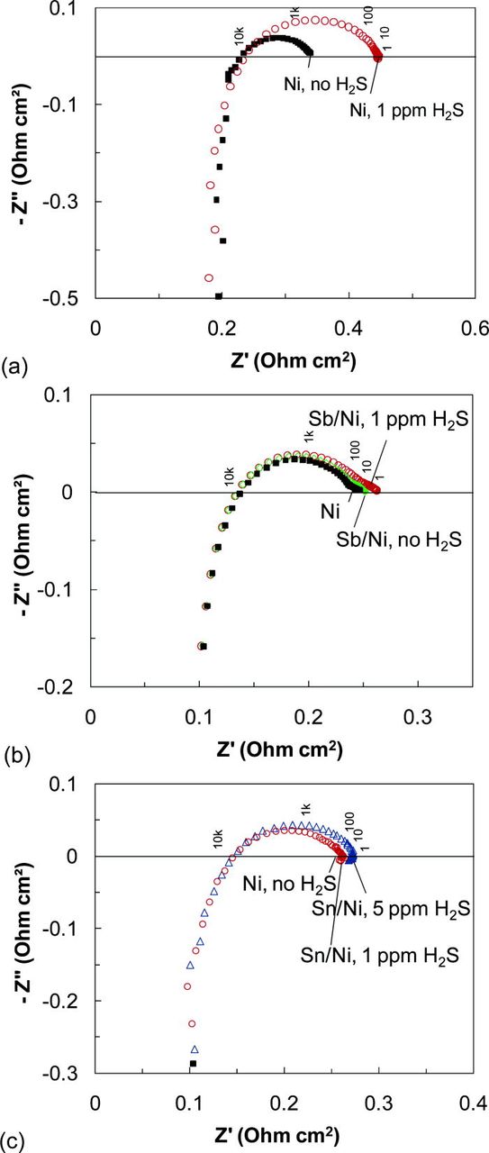
Figure 2. (Color online) Complex impedance spectra of (a) the Ni/YSZ anode-supported cell and cells with the Ni/YSZ anode pretreated for 1 h with (b) 1 ppm Sb and (c) 10 ppm Sn. Spectra were obtained in moist hydrogen at 800°C at a bias voltage of 0.7 V.
Neither Sb, nor S were detected on the anode surface by post-test SEM/EDS analyses, indicating minimal diffusion of either into the bulk Ni and no formation of higher order binary solid phases under the mild exposures used in this study. However, both Sb and S were found to be present on the Ni surface using XPS, which is sensitive to the outer-few atom layers of the sample surface. High energy resolution spectra of Sb 3d obtained from the SbNi/YSZ surface are shown in Fig. 3. Antimony was present on the nickel surface in both metallic and oxidized states, and only metallic Sb was found in the bulk following removal by sputtering of approximately the outer ∼20 nm layer. No special care was taken to isolate the anode surface from the environment (air) at room temperature after cooling the anode down in hydrogen, so the appearance of an oxidized form of Sb may be the result of air exposure. The Sb (oxidized and metallic)-to-Ni ratio was 0.32 ± 0.03 on the surface, and 0.19 ± 0.03 after sputtering. It is recognized that sputtering of these porous composites is certainly not uniform; the latter value is influenced by higher surface concentrations of Sb.
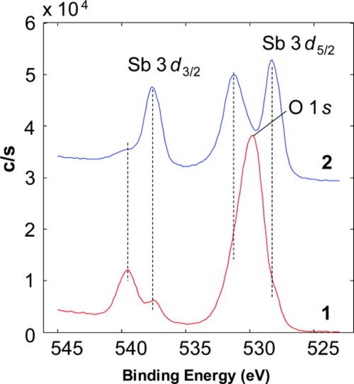
Figure 3. (Color online) High resolution photoemission spectra of the Sb 3d and O 1s region (1) before and (2) after 5 min 2 kV Ar+ sputter (sputter ∼ 20 nm) obtained from the SbNi/YSZ surface.
For Sb-treated Ni surfaces, the amount of sulfur was considerably less than that found on Ni/YSZ surfaces (the relative quantification included Ni, Sb, and S only) (Fig. 4). About 3.4 ± 0.3 atom % of S, established from the S 2p peaks, was determined on the Sb-pretreated Ni/YSZ surface that decreased to 1.6 ± 0.2 atom % after sputter and 14.9 ± 2 atom % of sulfur was found on the the Ni/YSZ anode without Sb pretreatment that decreased to 6.5 ± 0.7 atom % after sputter. That is, the amount of adsorbed S was reduced by more than a factor of 4 by exposure of Ni to Sb.
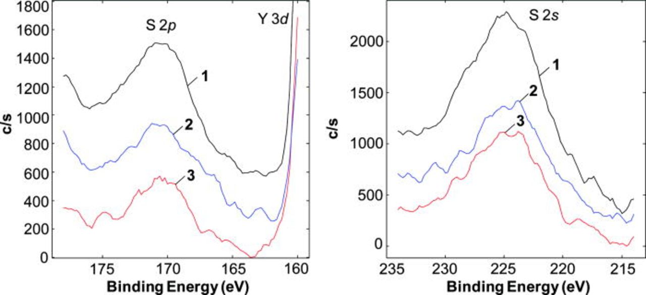
Figure 4. (Color online) High resolution photoemission spectra of the S 2p and S 2s regions obtained from (1) Ni/YSZ, (2) SnNi/YSZ, and (3) SbNi/YSZ surfaces.
Effect of Sn on H2S poisoning
When 10 ppm Sn was added to the fuel gas for 1 h, the cell resistance noticeably increased, and then fully recovered within a few hours after Sn exposure ceased. An initial performance loss due to Sn was expected, as more Sn would be initially present on the surface after exposure. The cell performance improved once the Sn excess (i.e., excess beyond that needed to form an adsorption layer) diffused into the bulk Ni. When 100 ppm Sn was added, a much larger performance loss was observed and no full performance recovery was attained in clean fuel gas. Therefore, such cells were not further tested with sulfur.
Subsequent addition of 1 ppm H2S to the fuel gas did not affect the cell voltage, and a steady performance close to that without H2S was observed during a 90-h test, as shown in Fig. 1. When the H2S concentration was increased to 5 ppm, the cell performance rapidly decreased by approximately 10% to a new steady state. As revealed by electrochemical impedance spectroscopy, the change in performance was electrodic in nature, as only the electrodic resistance was increased (Fig. 2c). This overall cell performance loss was substantially smaller than that normally observed for the Ni/YSZ in the presence of 1 ppm H2S under the same conditions (Fig. 2c).
Post-test SEM/EDS analyses were unable to detect any Sn in the SnNi/YSZ. XPS analyses of the SnNi/YSZ anode surfaces were performed to identify the Sn/Ni ratio, Sn oxidation state, and whether there was any sulfur adsorbed. Tin on the Ni surface appeared in both metallic and oxidized states and only metallic Sn was found following removal of the outer ∼20 nm by sputtering. As given in Fig. 5, the amount of Sn on the surface was higher compared to that in the bulk: A Sn/Ni atom ratio was 0.38 ± 0.04 before and 0.19 ± 0.03 after sputter. A small amount of sulfur was still detected on the anode surface (Fig. 4). A sulfur concentration of 3.9 ± 0.4 atom % (determined using the relative concentration of Ni, Sn, and S) before and 2.1 ± 0.3 atom % after sputter was determined. Bulk compounds with sulfur were neither detected by SEM/EDS, nor were they expected to be formed under the experimental conditions.

Figure 5. (Color online) High resolution photoemission spectra of the Sn 3d and O 1s region (1) before and (2) after 5 min 2kV Ar+ sputter (sputter ∼20 nm) obtained from the Sn/Ni/YSZ surface.
The high temperature stability of anodes prepared from a Ni–3% Sn solid solution was assessed in separate tests. These anodes were exposed to a synthesis gas with a composition of H2–CO–CO2–H2O = 33–22–23–22 vol %, quenched, and the Sn/Ni ratio on the surface and in the bulk was determined by XPS. It was found that Sn was mostly present in the oxide state on the surface and in the metallic state in the bulk, although this may be the result of air exposure prior to XPS analysis. The Sn/Ni ratio at the surface was determined to be 0.08 ± 0.01 and 0.03 ± 0.005 in the bulk, considerably lower than obtained in tests where the anode was exposed to Sn vapor, but consistent with observations of Sn surface segregation on Ni. Surface and bulk Sn/Ni ratios did not change with time during the whole test up to 870 h.
Effect of Sb on coke formation
The resistance of Ni/YSZ anodes to coking after Sb pre-exposure was evaluated while operating on moist hydrogen with 2 and 5 vol % methane added. After Ni was treated with 1 ppm Sb for 2 h, CH4 was introduced and cells were held at 0.8 V and the current density was monitored. No degradation over the 340 h test was observed (Fig. 6). The impedance data confirmed no change in the electrodic polarization. Post-test SEM analyses found no coke anywhere in the anode support.
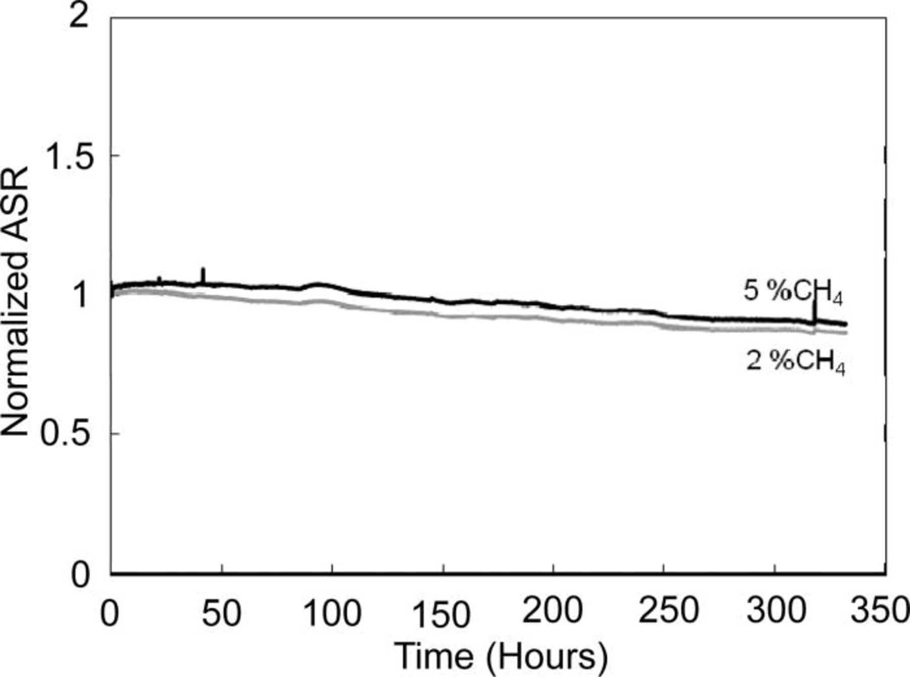
Figure 6. Area specific resistances (ASR) of cells during operation on fuel gas containing 2 and 5% methane. The slow ASR improvement is irrelevant to the present experiment and is a long-term drift, because a similar behavior was observed in the control cell operated simultaneously, but without methane.
Discussion
Sn and Sb surface segregation and stability
Brief exposures of Ni/YSZ anode-supported cells to small amounts of antimony or tin were found to result in rapid, although minor, losses in SOFC performance. Those losses, as identified by impedance spectroscopy, were mostly electrodic, which implies that Sb and Sn reached the active anode/electrolyte interface and slightly lowered the electrocatalytic activity for the hydrogen oxidation. When the concentrations of Sb and Sn were low, ∼1 and 10 ppm, respectively, and exposure times were short, ∼1 h, such poisoning was reversible and the cell performance recovered within several hours of operation on the clean fuel gas. No new solid Ni–Sb or Ni–Sn phases were found anywhere within the anode support or a functional anode by the post-test SEM analyses. The presence of adsorbed Sb and Sn on Ni/YSZ was verified by XPS. Based on these findings it is reasonable to suggest that surface adsorption of Sb and Sn onto nickel surfaces at the active anode/electrolyte interface was responsible for those small losses in SOFC performance.
The maximum quantity of Sb and Sn that may have deposited onto the anode surfaces in these tests was on the order of a few monolayers (ML). Assuming a 500 µm-thick anode support including the current collecting layer, a 1/1 Ni/YSZ volume ratio with 30% porosity, an average Ni particle diameter of 2 μm, half of which is exposed to fuel gases, a gas flow rate of 100 cm3/min cm2 containing 1 ppm Sb, and a saturation coverage of 0.33 Sb/Ni (Ref. 24), approximately 2 ML could be deposited in 1 h. Taking into account the structure of the Ni(111)(√3 × √3)R30°C–Sn surface,35 up to 20 ML of Sn could be deposited onto Ni in a similar time from a fuel gas stream containing 10 ppm Sn. Because the solubility of both Sb and Sn in Ni solid solution is significant, some of this material is expected to diffuse into bulk Ni grains. Thus, the quantity of Sb and Sn that was added to the anode was quite small.
The results of XPS analyses indicate that the concentrations of Sb and Sn remained enriched on the surface of Ni even after extended periods of operation at elevated temperatures. The Sb/Ni ratio near the active interface was 0.32 ± 0.03 following more than 100 h of operation at 800°C, which is consistent with saturation coverage of Sb on Ni surfaces reported by Krupski and Mroz.24 Similarly, the Sn/Ni ratio near the active interface was 0.38 ± 0.04 following similar operation times, which is consistent with saturation surface coverage of Sn on Ni reported by Soares et al.35 Following removal of the outer ∼20 nm by ion sputtering, the concentrations of both Sb and Sn decreased to 0.19 ± 0.03. These sputter depths are qualitative because of the uneven nature of the anodes. Surface concentrations of both Sb and Sn are well above those expected in solid solutions with Ni: at 800°C the solubility of Sb in Ni, according to Okamoto,36 is 8.5 atom %, whereas the solubility of Sn in Ni is 7.5 atom %, as given by Schmetterer et al.37 This is consistent with the previous findings where Sb and Sn exhibited the tendency to segregate to both surfaces19, 20, 23, 25, 26, 30, 38, 39 and grain boundaries.40–42 In particular, White and Padgett40, 41 have shown using Auger electron spectroscopy that segregation of antimony to the nickel grain boundaries was confined within a few atom layers. Some redistribution of both Sb and Sn is likely to have occurred after the initial exposure, however. Evidence for some redistribution includes observations that cell performance fell upon initial exposure to Sn and Sb, and substantially recovered within a few hours after exposure. Thus, initial surface coverages were likely to have been higher than those described previously.
The experimental times in this work were considerably longer than those needed for Sb and Sn to diffuse from the surface into the grains, so it is clear that enhanced surface concentrations of Sb and Sn are favored thermodynamically. Diffusion parameters for Sb diffusion in Ni (D0 = 1.8 × 10− 5) cm2/s and E = 113 kJ/mol) and for Sn diffusion in Ni (D0 = 0.83 cm2/s and E = 243 kJ/mol) have been given by Askill.43 If x ≈ (Dt1/2 ) is used as an estimate of the diffusion distance, Sb and Sn should migrate nearly 7 and more than 45 μm, respectively, in 100 h at 800°C, much more than the diameter of Ni particles. The fact that Sb and Sn did not dissipate is good evidence for stable surface segregation.
Although new Sb–Ni and Sn–Ni phases were not observed in post-test analysis by electron microscopy, thermodynamic stability calculations suggest that such products should be formed if exposure times were extended at similar concentrations. Figure 7 summarizes pertinent phase boundaries in coal gas as calculated using HSC Chemistry 6.12.34 At 800°C, solid products NiSb, Ni3Sn, and Ni3Sn2 are expected to form at Sb and Sn concentrations less than 0.01 ppm. For the low Sb and Sn dosages used in this study, however, reaction products were limited to surface adsorption layers and solid solution formation.
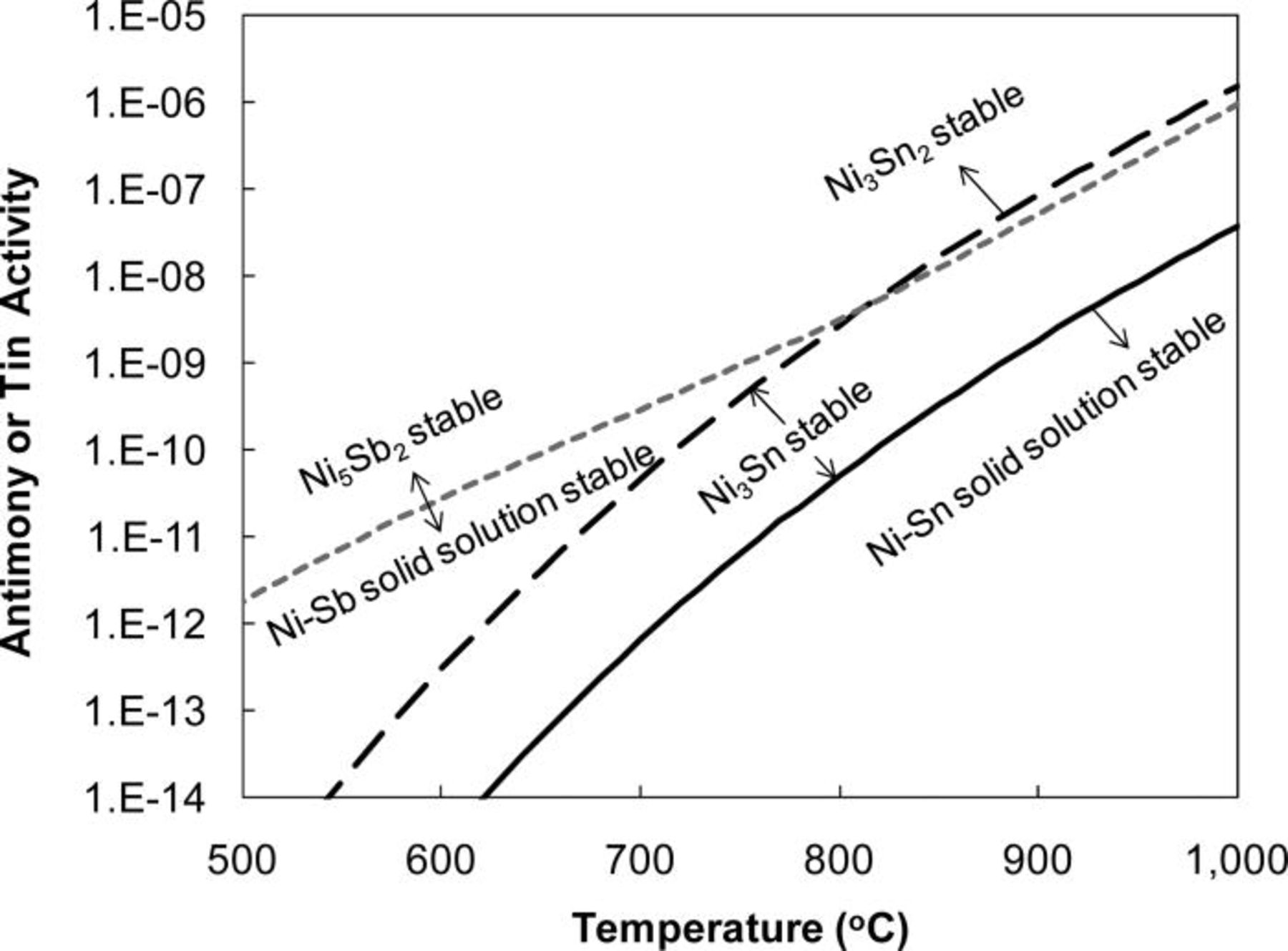
Figure 7. Predicted activities of gas-phase antimony and tin species in synthesis gas vs temperature. The formation of Ni3Sn and Ni3Sn2 phases is possible above corresponding lines. The formation of Ni3Sb, Ni5Sb2, and NiSb has been discussed in the previous study (Ref. 33).
XPS spectra indicate that adsorbed Sb and Sn were present in the oxidized state, and metallic peaks emerged at lower binding energy only after sputtering. For a solid solution of Sn and Sb in Ni, both should clearly be in the metallic form. As all of the XPS analyses were performed ex situ with no special care taken to protect the surface from environmental exposures (air) at room temperature, Sb and Sn oxidation most probably occurred post-experiment. During the in situ tests, at least at low fuel utilizations and low anode polarizations, only metallic Sb and Sn should have been present on the anode surface. This is in agreement with Li et al. ,38 who observed surface Ni–Sn alloys when Sn was adsorbed on each of three Ni, (100), (110), and (111) surfaces.
Improved resistance to sulfur poisoning
Hydrogen sulfide poisoning of nickel catalysis and nickel-based anodes is well documented to occur via the H2S dissociative adsorption on the nickel surface, and the formation of Ni–S bonds both reduces the H2 and CO chemisorption and decreases the Ni anode electocatalytic activity.1–7, 27, 44 In agreement with the previous findings,1–7 the presence of 1 ppm H2S in the fuel gas also decreased the activity of the Ni/YSZ anode in the present work (Fig. 1). Sulfur poisoning is generally explained by a combination of steric or structural (blocking of active sites) and electronic (charge redistribution or hybridization) effects.27, 44
The results of this work suggest that sulfur poisoning could be effectively inhibited by alloying the nickel with Sb or Sn, or by forming at least 1 ML of Sb or Sn on the nickel surface at the triple-phase boundary. When tin or antimony was added to the Ni/YSZ anode, the poisoning effect of sulfur was significantly diminished and in some cases was totally suppressed (Fig. 1). As determined by electrochemical impedance spectroscopy, the changes in the electrodic resistance of the Ni–Sb/YSZ and Ni–Sn/YSZ anodes were minimal compared to that of the Ni/YSZ anode (Fig. 2). The XPS results established lower relative concentrations of sulfur on both alloys compared to those on unaltered nickel: 3.4 atom % on Ni–Sb/YSZ and 3.9 atom % on Ni–Sn/YSZ compared to 14.9 atom % on Ni/YSZ. Thus, Ni surface enrichment with Sb or Sn suppresses reversible sulfur adsorption by a factor of approximately 4. Sulfur remained concentrated on the surface rather than having diffused into the Ni grains: in all cases, the concentration of sulfur was reduced by half following sputtering to a depth of ∼20 nm.
Several factors could contribute to increased tolerance of Sb- and Sn-modified SOFC anodes to sulfur. Site competition between sulfur and Sb or Sn at the active anode/electrolyte interface may be responsible, supported by findings described above that less sulfur remained on modified Ni surfaces. Other possibilities include weakened sulfur adsorptive bond strengths and a greater tendency for sulfur oxidation, particularly at high current densities. The possibility of new solid phase formation is considered as well.
Weakened reversible sulfur adsorption on Sb- and Sn-modified Ni surfaces may be a contributing cause of diminished SOFC performance losses due to sulfur exposure. Rodriguez et al.27 reported a substantial weakening in the Pt–S bonds on Sn/Pt and attributed this effect to the formation of Pt–Sn bonds and Sn/Pt alloy resulting in both electronic and geometric effects. Menegazzo et al.45 found that the presence of gold in Pd improved sulfur tolerance by a factor of 2; this was also attributed to the geometrical constrain in the bimetallic catalyst that was not suitable for the Pd4S formation. This was recently supported by Gan et al.46 first-principles calculations who predicted higher sulfur poisoning resistance of the bimetallic PdAu compared to the monometallic surfaces.
Another possible explanation to the improved sulfur resistance is site competition between preadsorbed Sb or Sn and sulfur, which could help to preserve the electrocatalytic activity of Ni. Given the strong tendency for Sb and Sn to segregate to the Ni surface or/and grain boundaries, either is likely to occupy the "reactive" surface adsorption sites, especially on stepped surfaces. There are many examples in the literature where the presence of one adsorbate hinders the adsorption of others. This explanation is commonly used to explain decreased adsorption of H2 and CO in the presence of S on the metal surface.44
In this study, we observed that the nickel activity toward the hydrogen oxidation was somewhat decreased once small quantities of Sn and Sb were added to the fuel gas, but then recovered after Sn and Sb diffused into the bulk. When the amount of tin was increased by a factor of ten (that is from 10 to 100 ppm), the cell performance significantly decreased likely due to Sn occupying the electrocatalytically reactive sites. A similar conclusion was made by Kan and Lee47 where the excessive Sn on the nickel surface lead to the significant decrease in cell power densities. Further, the activity toward the water gas-shift reaction, H2 + CO2 = H2O + CO, was observed experimentally to be suppressed on both Ni–Sb and Ni–Sn electrocatalysts. Such a conclusion was made from the fact that an open-circuit potential (which is directly related to the pH2/pH2O via the Nernst equation) increased when the cell was operated on the CO2 buffered hydrogen gas, indicating a higher pH2/pH2O compared to that in the absence of Sb or Sn. This is in agreement with previous studies where the catalytic properties of nickel have been shown to be altered by antimony and tin additions.20, 30, 39, 48–50 Dreiling and Schaffer51 predicted that Sb would alter the catalytic behavior of Ni due to both geometric and electronic effects. Goldwasser et al.49 reported decreased H2 and CO chemisorption on the Ni–Sb alloy and also attributed this to site blocking of nickel and weakening of the Ni–C bond. Parks48 also observed hydrogen chemisorptions poisoning on the surface segregated Ni–Sb alloy (NiSb). Similarly, Huber et al.39 observed that the addition of Sn to the Raney Ni weakened CO chemisorption. In each of these cases, the lowering of catalytic activity due to Sb or Sn adsorption was considerably less than that resulting from sulfur adsorption.
It also could not be excluded that Sn and Sb at the active interface are present in the oxidized or suboxidized state. In particular, Zhang et al.52 found that Sb impurities in stainless steels after heating to 800–850°C in moist hydrogen were present on the surface and grain boundaries in the oxide state. Because the oxides or suboxides have different affinity for sulfur than the metals, this would inhibit sulfur poisoning. Tin is among the metals least stable against oxidation. Although antimony is expected to be more stable than tin, the predominance diagrams calculated using HSC Chemistry 6.1234 indicate that both Sb and Sn are likely to be oxidized to Sb2O3 and SnO2 at high current densities and/or high fuel utilization (Fig. 8). At low fuel utilizations both Sn and Sb are stable in coal gas and are present as metals.
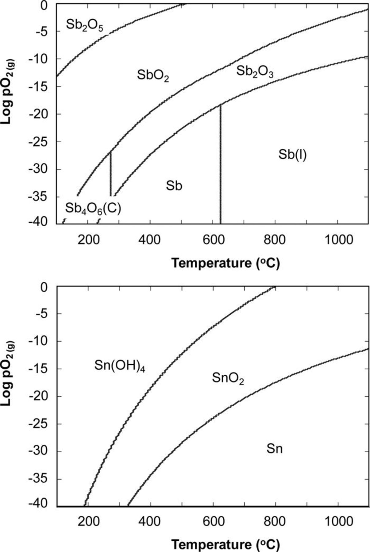
Figure 8. Predominance diagrams for Sb–H–O and Sn–H–O systems calculated at a fixed pH2 = 0.5 atm.
It is possible that sulfur is much easier to oxidize and remove, e.g., in the form of SO2 (Ref. 4), by O2− during the anode polarization on the Ni–Sn/YSZ and Ni–Sb/YSZ than on the Ni/YSZ. This mechanism has been described previously.4, 9 Because no high current densities that could lead to locally oxidizing conditions were used in this work, this is unlikely to contribute to the above-mentioned observations.
Suppressing of coke and recommendations
The addition of Sn and Sb weaken CO chemisorptions and, as a result, the use of bimetallic anodes may be beneficial in the suppression of coking when operating on the hydrocarbon fuel. Carbon deposition occurs mainly on Ni ensembles consisting of several neighboring Ni atoms. To prevent the formation of a Ni ensemble, Ni may be alloyed with another metal and Ni–Sb and Ni–Sn alloys have been shown to suppress the nickel activity for coke formation.19–21, 28–30 In the present work the stability of the Ni–Sb/YSZ electrodes for coking in the presence of methane was demonstrated. Tests with the NiSn/YSZ anodes were not conducted, because of the extensive prior art indicating the stability of Ni–Sn to coking.19, 21, 28–30 Very recently, Kan and Lee47 reported that Ni/YSZ anodes doped with Sn at low levels exhibited long-term stability when operated on nearly dry methane. The quantity and distribution of Sn on the anode surface remained unchanged over the course of operation. Higher levels of Sn doping resulted in the occupation of most catalytic active sites, causing poorer performances. It is possible that NiSb electrodes would exhibit long-term stability in dry hydrocarbons as well, and this could be suggested as an area for future studies.
Summary
The Ni/YSZ anode resistance to sulfur poisoning was enhanced by brief pre-exposures of the anode-supported SOFCs to metallic Sb and Sn vapor. Although only a minor effect on the hydrogen oxidation was observed, the sulfur tolerance of such anodes was substantially improved. X-ray photoelectron spectroscopy was used for characterizing the Sn–Ni and Sb–Ni interactions and the obtained results indicated the Ni–Sn and Ni–Sb alloy formation as well as surface enrichment with Sn or Sb. Both Ni–Sn and Ni–Sb alloys were suggested to play an important role in weakening sulfur adsorption on nickel. Results of this work indicate that bimetallic surfaces maybe effective in controlling or preventing sulfur poisoning in the SOFC anodes and Ni catalysis. It is also possible that low level exposure to impurities, such as P and As would have a similar sulfur poisoning suppressing effect.
ACKNOWLEDGMENTS
The technical contributions of J. F. Bonnett, G. W. Coffey, C. N. Cramer, Dr. D. J. Edwards, Dr. P. Nachimuthu, A. L. Schemer-Kohrn, and E. C. Thomsen are gratefully acknowledged. This work was supported by the U.S. Department of Energy, Office of Fossil Energy, National Energy Technology Laboratory through the SECA Coal-Based Systems Core Research Program. A portion of this research was performed using EMSL, a national scientific user facility sponsored by the Department of Energy's Office of Biological and Environmental Research and located at Pacific Northwest National Laboratory. Pacific Northwest National Laboratory is operated for the U.S. Department of Energy by Battelle under Contract No. AC06-76RLO 1830.
Pacific Northwest National Laboratory assisted in meeting the publication costs of this article.