
Abstract
Electrochemical production of hydrogen from water requires the development of electrocatalysts that are active, stable, and low-cost for water splitting. To address these challenges, researchers are increasingly exploring binder-free electrocatalytic integrated electrodes (IEs) as an alternative to conventional powder-based electrode preparation methods, for the former is highly desirable to improve the catalytic activity and long-term stability for large-scale applications of electrocatalysts. Herein, we demonstrate a laser-induced hydrothermal reaction (LIHR) technique to grow NiMoO4 nanosheets on nickel foam, which is then calcined under H2/Ar mixed gases to prepare the IE IE-NiMo-LR. This electrode exhibits superior hydrogen evolution reaction performance, requiring overpotentials of 59, 116 and 143 mV to achieve current densities of 100, 500 and 1000 mA·cm−2. During the 350 h chronopotentiometry test at current densities of 100 and 500 mA·cm−2, the overpotential remains essentially unchanged. In addition, NiFe-layered double hydroxide grown on Ni foam is also fabricated with the same LIHR method and coupled with IE-NiMo-IR to achieve water splitting. This combination exhibits excellent durability under industrial current density. The energy consumption and production efficiency of the LIHR method are systematically compared with the conventional hydrothermal method. The LIHR method significantly improves the production rate by over 19 times, while consuming only 27.78% of the total energy required by conventional hydrothermal methods to achieve the same production.
Highlights
Electrodes with NiMoO4 nanosheet arrays were fabricated by rapid laser scanning over nickel foam in a precursor solution.
The LIHR method significantly increased the production rate 19 times faster, using only 27.78% of the energy compared to conventional hydrothermal methods.
The integrated electrode IE-NiMo-LR exhibits superior hydrogen evolution reaction performance, requiring low overpotentials to achieve high current densities and maintaining stability over 350 h.
The IE-NiMo-LR/IE-NiFe-L pair efficiently splits water, needing only 1.55 V to reach 100 mA·cm−2 in 1 M KOH electrolyte.
Export citation and abstract BibTeX RIS

Original content from this work may be used under the terms of the Creative Commons Attribution 4.0 license. Any further distribution of this work must maintain attribution to the author(s) and the title of the work, journal citation and DOI.
1. Introduction
Electrochemical water splitting for hydrogen production with renewable power sources has been considered as a promising and environmentally friendly technology for energy conversion and storage [1–3]. However, its large-scale practical utilization is hindered by the high cost of electricity and the need for catalysts that play a critical role in overcoming the kinetic energy barriers for hydrogen evolution reaction (HER) and oxygen evolution reaction (OER). Currently, platinum group metals and their oxides are widely used to lower the overpotential of water electrolysis and exhibit high catalytic activities for HER and OER [4–6]. Due to their scarcity, high cost and poisoning by chemicals, their uses as electrode materials in the mass production of hydrogen are limited [7, 8]. Therefore, the development of highly active, stable, cost-effective and robust electrocatalysts is needed to minimize the electricity consumption and reduce the overall cost.
In the past few decades, numerous efforts have been devoted to the research and development of alternatives to Pt-based electrocatalysts, including earth-abundant elements like transition-metals [9] and their oxides [10–12], carbides [13], and composites [14]. Among these candidates, nickel-based catalysts, particularly Ni–Mo catalysts, have gained widespread recognition for alkaline HER [15, 16]. This recognition is primarily attributed to their enhanced electrocatalytic activity compared to pure Ni, suitable binding energy to intermediates, and good resistance to harsh electrolyte environments [17–20]. On the other hand, layered double hydroxides (LDHs) based on transition metals (Fe, Co, Ni) have been also reported to be one of the most active OER catalysts in alkaline media due to their unique two-dimensional structure and excellent physical and chemical properties [21, 22]. In addition to the development of highly efficient electrocatalyst materials, the fabrication of electrocatalytic electrodes is also critical to accelerating the commercialization of electrocatalysts as well as energy conversion devices. Currently, most of the electrocatalysts are powder-based. Electrode preparation follows a coating route involving the use of low conductive polymeric binders, which may elevate resistance levels, block active sites, impede mass transport and consequently lead to a degradation in catalytic performance [23, 24]. Additionally, continuous gas evolution during electrochemical reactions may also result in detachment of the electrocatalysts. Recently, various binder-free integrated electrocatalytic electrodes have been reported, including electrocatalysts that directly grow on conductive substrates [25, 26] or generate free-standing films [27, 28]. In comparison with the conventional powder-based electrodes, the integrated electrodes (IEs) with convenient and time-efficient preparation procedures have shown excellent activity and stability [24, 25]. Among various fabrication methods, a hydrothermal method is well-recognized. For example, Chen et al prepared a binder-free MoNi4/MoO3−x nano-array electrode via solvothermal reaction followed by subsequent annealing under a reducing atmosphere [29]. The resultant electrode exhibited remarkable HER activity with an overpotential of 114 mV at 500 mA·cm−2. Stable overall water splitting was achieved in a water-alkaline electrolyzer using MoNi4/MoO3−x as the cathode with a low cell voltage of 1.6 V at a current density of 30 mA·cm−2. However, hydrothermal or solvothermal synthesis typically requires a long reaction time, and high energy consumption, and is carried out within pressurized vessels that may raise safety concerns [30]. Therefore, it is highly desirable to develop a fabrication method for electrocatalytic electrodes which is time-efficient, versatile, green, low-cost, and suitable for large-scale production.
In the past decade, considerable interest has been attracted to the development of the rapid synthesis of catalysts. Methods including microwave synthesis [31, 32], Joule heating [33–35], and induction heating [36] have been investigated. For example, Zhong et al developed a fast and efficient method for the preparation of uniformly dispersed metal oxide nanoparticles on a 3D carbonized wood (C-wood) using 3D microwave heating [32]. Firstly, the C-wood with highly porous structures was obtained via high-temperature furnace treatment of basswood, which is beneficial for mass transfer and loading of metal salts. Then, 3D C-wood with well-dispersed metal oxide nanoparticles was rapidly prepared under an air atmosphere by microwave heating. Yang et al used a 3D carbonized wood as the substrate to in situ synthesize CoFeOx nanoparticles by the Joule heating method [35]. This was achieved by joule heating of the carbonized wood loaded with metal salt precursors under the Ar atmosphere, and the resultant CoFeOx nanoparticles were directly used as an OER electrocatalyst. Xiong et al synthesized various electrocatalysts on Ni foam (NF) via induction heating [37]. Although these methods have demonstrated great potential in the large-scale synthesis of nanomaterials, there are still some limitations. For instance, microwave synthesis, induction heating and Joule heating can only be carried out on specific substrates with good conductivity or polar molecules, which narrows the range of catalysts that can be synthesized [38].
Recently, lasers used as a synthetic technique provide an alternative route for nanomaterial fabrication [39]. Compared with the synthesis techniques described above, laser-assisted techniques enable the direct preparation of nanomaterials in both gas [40] and liquid environments [41], and the morphologies of nanomaterials like nanostructured metal oxides are determined by the choice of laser wavelength, pulse width, repetition rate, and processing media [41]. The laser synthesis enables an in-situ and site-specific oriented growth of nanomaterials via laser-induced thermo-chemical reactions and demonstrates a unique feature of spatially confined reactions and 3D compatibility. Sha et al proposed a strategy based on phase separation and laser-induced methods to prepare integrated catalyst electrodes [25]. Firstly, a 3D interconnected porous catalyst precursor layer was obtained by the phase separation between a polybenzimidazole solution and a coagulation bath containing salt precursors. After drying, IEs were fabricated via laser irradiation in an ambient atmosphere, which simultaneously converted polybenzimidazole (PBI) into hierarchically porous laser-induced graphene and reduced salt precursors into tiny nanoparticles. In addition, lasers have been also applied to grow nanostructured metal oxide thin films on various substrates by laser irradiation of a substrate immersed in a liquid containing metal salt precursor. It was believed that the laser beam interaction at the interface between the liquid and substrate generated a condition of high temperature and high pressure, which satisfies the requirement of metal oxide growth on the substrate through hydrothermal reaction mechanism. Therefore, it is termed a laser-induced hydrothermal reaction (LIHR). Rajab et al successfully grew various ZnO nanostructures including nanorods, nanosheets, and nanoflowers on substrates by adjusting laser settings and chemical environments and achieved the same efficacy as a traditional hydrothermal reaction but with a remarkably short period of time [42]. Similarly, Yeo et al synthesized ZnO nanowires via LIHR [43]. However, up to date, very limited nanostructured metal oxides, such as ZnO [42] and MnO2 [44], were synthesized by LIHRs, and their potential for the fabrication of electrocatalysts and IEs has not been explored. In addition, most LIHR-related processes were static, and the irradiation time required for reactions to take place was up to several minutes. Therefore, it limits the processing efficiency and its potential for roll-to-roll manufacturing of electrocatalytic IEs in the future.
In this work, a new method of LIHR was developed. Electrodes with NiMoO4 nanosheet arrays were obtained after rapid laser scanning on the bare nickel foam immersed in a small amount of precursor solution. The electrodes reduced after calcination under H2/Ar mixed gas exhibited superior HER performance and stability compared to electrodes prepared by traditional hydrothermal reaction. In addition, the electrode was further used as a cathodic electrode in alkaline water splitting, while an electrode with NiFe LDH nanosheet arrays fabricated by LIHR was used as an anodic electrode. The whole water-splitting reaction showed excellent performance and durability. Finally, the production efficiency and energy consumption related to CO2 emission between laser hydrothermal reaction and traditional thermal reaction were compared in detail.
Therefore, this method is rapid, versatile, and cost-effective, and opens up a new avenue towards rapid synthesis of electrocatalytic electrodes.
2. Experimental section
2.1. Chemicals and materials
Chemicals, including ammonium molybdate [(NH4)6Mo7O24 · 4H2O, Sigma Aldrich], nickel nitrate hexahydrate [Ni(NO3)2 · 6H2O, Sigma Aldrich], iron(III) nitrate nonahydrate [Fe(NO3)3 · 9H2O, Sigma Aldrich], ammonium fluoride (NH4F, Alfa Aesar), potassium hydroxide (KOH, Sigma Aldrich), platinum carbon (Pt/C, nominally 20% on carbon black, Alfa Aesar) and Nafion solution (5% in lower aliphatic alcohols and water, Sigma Aldrich), were used as received without further purification, except dilution using deionized water (15 MΩ cm). NF was applied as substrate material.
2.2. Synthetic procedures
2.2.1. Preparation of IE-NiMo-L or IE-NiFe-L.
The fabrication of catalytic IEs based on LIHT is illustrated in figure 1(a). Firstly, a piece of NF (purity >99.99%, 15 mm × 15 mm × 1 mm) was cleaned with 3 M HCl solution for 30 min to remove the surface oxide layer and then washed with deionized (DI) water and ethanol for three times respectively.
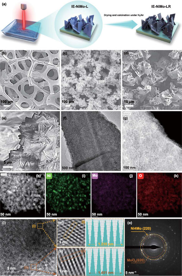
Figure 1. Fabrication of NiMo/NF by laser-induced hydrothermal reaction and characterization of the resultant products. (a) Schematic illustration of the preparation of IE-NiMo-LR via LIHR and subsequent hydrogen–argon reduction. (b)–(e) Corresponding SEM images at different synthetic stages. (f) TEM image, (g) HAADF-STEM image of NiMoO4 nanosheet of IE-NiMo-L. (h)–(k) HAADF-STEM image of Ni4Mo/MoO2 nanosheets of IE-NiMo-LR and corresponding EDS mapping of elements (i) Ni, (j) Mo, (k) O. (l)-(n) HRTEM image and (o) SAED image of Ni4Mo/MoO2 nanosheets of IE-NiMo-LR.
Download figure:
Standard image High-resolution imageFor IE-NiMo-L, 5 mmol (NH4)6Mo7O24 · 4H2O and 20 mmol Ni(NO3)2 · 6H2O were dissolved homogeneously in 20 ml DI water in a glass bottle. The NF was immersed in the mixed solution before LIHR. During the LIHR period, NF was placed at the bottom of a crucible and dipped with 1 ml mixed solution to keep the NF fully wetted and provide enough reactants. The solution level above the sample was about 1 mm. Then, a pulsed fibre laser (ytterbium single-mode fibre laser (YLP-500-WC, IPG) with 1070 nm of wavelength and a maximum power of 500 W) was used, and an over-focus laser beam setting with a spot size of 1 cm in diameter was applied. The raster laser scanning controlled by computer numerical control (CNC) was carried out under ambient conditions with a laser fluence 191.1–636.9 mJ·cm−2, a pulse repetition rate of 100 Hz, a scanning rate of 10 mm·s−1 and a hatch distance of 5 mm. One side of NF took 7 s for LIHR treatment. Therefore, both sides took 14 s in total. The laser operation time was measured via Mach 3 CNC software. The light-green IE-NiMo-L was obtained after drying.
For IE-NiFe-L, 5 mmol Fe(NO3)3 · 9H2O and 20 mmol Ni(NO3)2 · 6H2O were dissolved homogeneously in 20 ml DI water in a glass bottle. Similar to the previous procedure, the NF was immersed in this solution before LIHR. The raster laser scanning controlled by CNC was carried out under ambient conditions with a laser fluence of 382.2 mJ·cm−2. The pulse repetition rate, scanning rate and hatch distance were also consistent with those employed for IE-NiMo-L. The NF was subjected to 7 s of LIHR treatment on each side, totalling 14 s for both sides. The laser operation time was measured using the Mach 3 CNC software. Following the drying process, the yellow IE-NiFe-L was obtained.
2.2.2. Preparation of IE-NiMo-H or IE-NiFe-H.
To distinguish the IE-NiMo-L and IE-NiFe-L prepared by LIHR, the corresponding IE synthesized by traditional hydrothermal method using autoclaves is represented by IE-NiMo-H and IE-NiFe-H. Firstly, a piece of NF (purity >99.99%, 40 mm × 60 mm × 1 mm) was cleaned with 3 M HCl solution for 30 min to remove the surface oxide layer and then washed with DI water and ethanol for three times respectively.
For IE-NiMo-L, 0.6 mmol (NH4)6Mo7O24 · 4H2O and 2.4 mmol Ni(NO3)2 · 6H2O were dissolved homogeneously in 60 ml DI water. Finally, the above solution and NF were transferred to a Teflon-lined stainless-steel autoclave (100 ml). CARBOLITE PF30 (200) furnace system with a maximum temperature of 300 °C was used for traditional hydrothermal reaction. The heating procedure had four stages according to the safety instructions of using an autoclave for hydrothermal reaction. At stage I, the temperature was raised from 21 °C to 120 °C. This temperature was maintained for one hour at stage II. After that, the temperature was raised to 160 °C at stage III. Finally, the temperature was kept for 6 h for stage IV. After naturally cooling down, the light-green IE-NiMo-H can be obtained.
For IE-NiFe-L, 0.6 mmol Fe(NO3)3 · 9H2O and 2.4 mmol Ni(NO3)2 · 6H2O were dissolved homogeneously in 60 ml DI water. Similar to the previous procedure, the NF was immersed in this solution before the hydrothermal reaction. Finally, the above solution and NF were transferred to a Teflon-lined stainless-steel autoclave (100 ml). The furnace heating procedure was the same as that of IE-NiMo-H.
2.2.3. Preparation of IE-NiMo-LR or IE-NiMo-HR.
The IE-NiMo-L or IE-NiMo-H was placed in a tube furnace. Then Ar was introduced for 30 min to remove air and heated up to 500 °C with a rate of 5 °C·min−1. After that, a reductive atmosphere composed of a mixture of Ar (95%) and H2 (5%) was employed. The IE-NiMo-H was annealed at 500 °C under this reductive atmosphere for 2 h to prepare IE-NiMo-HR. Finally, the gas valve was switched to Ar, and the furnace was cooled to room temperature. The resultant black IE-NiMo-LR or IE-NiMo-HR was obtained after naturally cooling down.
2.2.4. Preparation of Pt/C or RuO2.
To prepare the Pt/C or RuO2 catalytic electrode, commercial Pt/C or RuO2 catalysts were deposited onto NF. The procedure involved mixing 20 mg of 20 wt% Pt/C or RuO2, 0.02 ml of 5% Nafion solution, 0.49 ml of isopropanol, and another 0.49 ml of isopropanol. The resulting mixture was ultrasonicated for 1 h to obtain a uniform ink. Then, the ink was coated on clean NF with a controlled loading of 2 mg·cm−2.
2.2.5. Materials characterization.
The morphology and elemental distribution of as-prepared materials were comprehensively analysed by scanning electron microscopy (SEM) on a field-emission Zeiss Merlin SEM equipped with an extreme energy-dispersive x-ray spectroscopy (EDS) detector, operating at 3 kV. The high-resolution transmission electron microscopy (HRTEM) images, high-angle annular dark-field scanning transmission electron microscopy (HAADF-STEM) images and EDS analysis were carried out on a field emission FEI Talos F200 X S/TEM equipped with a high-efficiency Super-X EDS detector, operating at 200 kV. X-ray diffraction (XRD) was used to determine the crystalline structures by using Bruker D8 discover x-ray diffractometer with a Cu anode ((λ = 1.5418 Å), operating at 40 kV. X-ray photoelectron spectroscopy (XPS) was performed by using a high-throughput Scienta Omicron XPS system; the XPS spectra were corrected with respect to the C 1s peak at 284.8 eV and fitted by CasaXPS software.
2.2.6. Electrochemical characterization.
Electrochemical measurements of the as-prepared catalyst electrodes were carried out on a potentiostat (VersaSTAT4 Potentiostat Galvanostat, AMETEK). In a typical three-electrode configuration, the as-prepared IEs, with the geometric surface area of each IE in the electrolyte is 0.5–1 cm2, the graphite rod and Hg/HgO electrode with 1 M KOH filling solution were applied as working, counter and reference electrodes, respectively. The 1 M KOH was used as an electrolyte. The measured electrode potentials corresponding to the Hg/HgO reference electrode were concerted to the reversible hydrogen electrode (RHE) potentials according to the following Nernst equation:

where ERHE is the potential in the RHE scale, and E(Hg/HgO) is the measured potential against the Hg/HgO reference electrode, E0 (Hg/HgO) = 0.098 V at 25 °C.
The scanning rate for linear sweep voltammetry (LSV) tests was 5 mV·s−1 and 90% iR compensation was used for all electrochemical measurements. The HER or OER polarization curves were collected after at least 100 cyclic voltammetry (CV) cycles of activation and stabilization. Before each test, the electrolyte was bubbled with Ar for 15 min to remove dissolved oxygen in the solution. The Tafel slope (b) was calculated using the equation η = a + b log (j), where η is the overpotential and j is the current density. Electrochemical impedance spectroscopy (EIS) was tested at a constant potential of −0.05 V vs RHE (overpotential of 50 mV for HER) in 1 M KOH with a frequency range from 100 kHz to 0.01 Hz.
Chronopotentiometry measurements were performed at current densities of 100 and 500 mA·cm−2 in 1 M KOH for 300 h. Overall water splitting was performed in an H-type electrolyzer with IE-NiMo-LR as the cathodic electrode, IE-NiFe-L as an anodic electrode and an anion-exchange membrane as separator (Alkymer®, EVE Institute of New Energy Technology).
2.2.7. Calculation of specific activity.
Specific activity quantifies the current density relative to the electrochemical surface area (ECSA). The ECSA of IEs was estimated by the double-layer capacitance of electrodes. The ECSA was calculated by the following equation:


where Cdl represents the double-layer capacitance of electrodes in a non-Faradic potential range, and Cs is the specific capacitance of the sample. The Cs of platinum and IEs were assumed as 62 μF·cm‒2 and 40 μF·cm‒2, respectively. Cdl is the slope of the charging current ic, with respect to scan rate v. The ECSA has a linear relation with the double-layer capacitance (Cdl). The Cdl value can be subtracted from CV curves against different scan rates. The selected potential window for CV was beyond the possible Faraday region of the materials. Thus, the AECSA of NF, IE-NiMo-L, Pt/C, IE-NiMo-HR, and IE-NiMo-LR were calculated as 160, 140, 687.5, 3400, and 6675 cm2. The specific activity was then obtained by normalizing the current density to the ECSA value.
2.2.8. Calculation of TOF.
The turnover frequency (TOF) value of HER was estimated using the following equation:

The total number of hydrogen turnovers:

We estimated the number of active sites as the total number of the surface sites from the roughness factor together with the unit cell of the catalysts, which will underestimate the actual TOF. Taking IE-NiMo-LR or IE-NiMo-HR as an example, the active sites were from the multiphase of Ni4Mo and MoO2. Thus, the number of active sites (all Ni, Mo, and O atoms were included as active sites) per unit of actual surface area can be calculated below:
Therefore, the number of active sites for IE-NiMo-LR is around 1.92 × 10¹⁵ atoms cm−2. The number of active sites for other catalysts is calculated as below,
The plots of current density can be converted into TOF plots using the following formula:
2.2.9. Unit process carbon footprint.
The energy consumption of the furnace and each component of the laser system, including laser generator, water chiller, CNC system, functional generator, and computer control system, was measured using a Fluke 434 power/energy analyser. The carbon emissions of each processing system were calculated using the following equation:
where  (kgCO2) is the carbon emission of total electricity used.
  (kJ) is the total energy usage during the whole process.
  is the carbon emission signature calculated from the energy mix that supplies electrical power.
3. Results and discussion
The morphology of IE-NiMo-L was characterized by SEM first, showing the dense microarrays composed of nickel molybdate nanosheets uniformly grow on NF after the rapid LIHR process (figures 1(c), (e), and S1). Transmission electron microscopy (TEM) characterization shows that the NiMo precursor nanosheet of IE-NiMo-L has a thin porous 2D nanosheet structure with lateral size in a micrometre scale (figure 1(f)). Such morphology is different from the widely investigated NiMoO4 microrods obtained by the traditional hydrothermal method (figure S2). HAADF-STEM images also indicate that the NiMo precursor nanosheets have a rough surface with dense pores (figure 1(g)). This is beneficial for thoroughly reacting with H2/Ar mixed gases during the subsequent reduction and also exposing more active sites during HER. As shown in figure S3, the uniform distributions of elemental Ni, Mo and O in NiMo precursor nanosheet were confirmed by STEM-energy dispersive spectroscopy (EDS) mapping. The XRD results indicate the successful synthesis of NiMoO4 precursor (figures S4(a)). Figure S4(b) shows the selected area electron diffraction (SAED) pattern of the NiMoO4 precursor. The diffraction rings correspond to (1 1 0) and (−1 3 1) planes of NiMoO4, which further confirms the polycrystalline nature of NiMoO4 and is consistent with the XRD results. For LIHR processing, the effect of laser fluences on the preparation of IE-NiMo-L was investigated. Compared with IE-NiMo-L prepared under laser fluence of 382.2 mJ·cm−2, fewer NiMoO4 nanosheets were sparsely distributed on electrodes obtained under lower laser fluences (figures S5(a) and (b)). As can be seen from figures S5(d) and (e), only big metal oxide clusters can be obtained under higher laser fluences (above 382.2 mJ·cm−2) due to melt coalescence caused by high laser fluence synthesis in liquid. Therefore, the optimal laser fluence of 382.2 mJ·cm−2 was used in this study to ensure the dense and uniform growth of NiMoO4 precursor nanosheet arrays on the NF substrate.
As shown in figure 1(d), the features of nanosheet arrays are well maintained after subsequent annealing under a reductive atmosphere. HAADF-STEM image shows that the dense and tiny nanoparticles anchored on the surface of nanosheets and 3D hierarchical porous structures and channels are newly formed due to the loss of water molecules and partial removal of oxygen atoms during thermal reduction under the H2/Ar gas flow (figure 1(h)). Such open 3D microstructures are expected to facilitate electrolyte diffusion and expose more active sites during HER. According to the STEM-EDS mapping, Mo and O are evenly dispersed through the nanosheet while Ni mainly exists granularly on the surface of nanosheets (figures 1(i)–(k)). HRTEM was also conducted to identify the lattice plane structures. The nanosheet exhibits an amorphous state in some regions, while the (220) plane of Ni4Mo and (020) plane of MoO2 correspond to typical lattice spacings of 0.20 nm and 0.24 nm, respectively (figures 1(l)–(n)). In addition, characteristic diffraction rings of the facets, including (220) of Ni4Mo and (020) of MoO2 can be indexed from the SAED pattern (figure 1(o)). As indicated in figure 2(a), the XRD results of IE-NiMo-LR also confirm the existence of Ni4Mo and MoO2 phases, which is consistent with the samples prepared with traditional hydrothermal reaction and subsequent reduction calcination [45]. Therefore, it can be concluded that the multiphase product consisting of Ni4Mo/MoO2 and porous Mo oxide matrix is successfully synthesized after reduction. This is consistent with the previous studies. The mechanism of structural transfer under reductive annealing was revealed by Patil et al by using in situ environmental TEM [46]. The reduction is preferential to occur on Ni sites, and Mo oxide is partially reduced by gas spillover from Ni, leading to the phase separation between metallic Ni-rich alloy nanoparticles and Mo-rich oxides. The surface elemental composition and chemical states were further characterized by XPS. The prominent peaks in the survey spectrum were identified as Ni 2p, Mo 3d, C 1s and O 1s (figure S6). The high-resolution XPS spectrum of Ni 2p and Mo 3d were also investigated. As shown in figure 2(b), two spin–orbit peaks around 855.8 eV and 873.4 eV corresponding to Ni2+ can be observed in both samples. After reduction, metallic Ni0 at 853.4 and 870.6 eV emerged in IE-NiMo-LR. The relatively low intensity of the Ni0 peak is ascribed to surface oxidation after exposure to an air atmosphere. Similarly, high-valence Mo (Mo3+ at 230.0 and 233.1 eV, Mo4+ at 231.3 and 234.2 eV, Mo6+ at 232.6 and 235.7 eV) exists in NiMoO4 precursor of IE-NiMo-L (figure 2(c)). After reduction, corresponding Mo peaks were negatively shifted and tiny Mo0 peaks were observed, confirming a partial reduction of Mo.
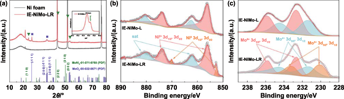
Figure 2. XRD and XPS analysis of IE-NiMo-L and IE-NiMo-LR. (a) XRD patterns of IE-NiMo-LR and Ni foam along with standard PDF cards for MoNi4 and MoO2. High-resolution XPS spectra of (b) Ni and (c) Mo for IE-NiMo-L and IE-NiMo-LR.
Download figure:
Standard image High-resolution imageThe HER performance of as-prepared IE-NiMo-LR was measured by using it directly as a working electrode in a typical three-electrode electrolytic cell with 1 M KOH as electrolyte. For comparison, NF, Pt/C catalyst, IE-NiMo-L and IE-NiMo-HR were also investigated under the same conditions. The HER LSV curves were obtained at a scanning rate of 5 mV·s−1. As shown in figure 3(a), IE-NiMo-LR requires the lowest overpotentials (η) of 59, 116 and 143 mV to achieve current densities of 100, 500 and 1000 mA·cm−2, which are marginally lower than IE-NiMo-HR (73, 153 and 193 mV) and much lower than those for IE-NiMo-L (299, 401 and 450 mV), NF (396, 541 and 615 mV) and Pt/C (203, 467 and 567 mV), indicating excellent HER activity of IE-NiMo-LR. In addition, the HER kinetics of the catalysts were studied by Tafel slope, which exhibits consistent trends. As shown in figure 3(b), IE-NiMo-LR has a Tafel slope of 36.4 mV·dec−1, which is significantly smaller than those of Pt/C, IE-NiMo-L, IE-NiMo-HR and NF. The low overpotential and Tafel slope of IE-NiMo-LR outperform the majority of literature values (figure 3(c) and table S1, supporting information). The poor performance of Pt/C for HER is ascribed to a weakened adhesion between Pt/C and Ni form, which can be traced back to the ink coating process.

Figure 3. HER performance of NiMo/NF in 1 M KOH. (a) Polarization curves and (b) corresponding Tafel plots of IE-NiMo-LR, IE-NiMo-HR, IE-NiMo-L, NF and Pt/C. (c) Comparison of HER catalytic activity between IE-NiMo-LR and other catalytic electrodes. (d) and (e) Chronopotentiometric tests of IE-NiMo-LR and Pt/C at constant current densities of 100 and 500 mA·cm−2. (f) Overall water splitting performance of IE-NiMo-LR, IE-NiFe-L pairs and Pt/C, RuO2 in 1 M KOH. (g) Comparison of water splitting voltage at 100 mA·cm−2 between IE-NiMo-LR and IE-NiFe-L pair with other electrocatalytic electrodes. (h) Chronopotentiometric tests of IE-NiMo-LR and IE-NiFe-L pairs at current density of 500 mA·cm−2.
Download figure:
Standard image High-resolution imageTo better understand the origin of the enhanced electrocatalytic performance of IE-NiMo-LR, the electrochemically active surface area (ECSA), EIS and TOF analysis were conducted. ECSA is strongly related to the number of active sites and has a linear relationship with double-layer capacitance (Cdl). As shown in figure S7, IE-NiMo-LR has a larger Cdl (275 mF·cm−2) than IE-NiMo-HR (136 mF·cm−2) and is significantly bigger than Pt/C, IE-NiMo-L and NF (figure S7). When the current density is normalized by ECSA, IE-NiMo-LR shows similar results to IE-NiMo-HR, indicating these two IEs have similar intrinsic activity (figure S8). According to the Nyquist plots, IE-NiMo-LR also has a similar charge-transfer resistance (Rct) as that of IE-NiMo-HR (figure S9). In addition, the TOF value of IE-NiMo-LR is calculated to be 0.417 s−1 at the potential of −0.18 V versus RHE, which is marginally bigger than that of IE-NiMo-HR (0.377 s−1) (figure S10). Therefore, it is notable that the excellent HER performance originated from its large specific surface area in addition to its good intrinsic activity. The 2D and porous structures of NiMoO4 nanosheets of IE-NiMo-L prepared by LIHR facilitate the ultimate contact between alloy oxide and reductive gas flow, thus enhancing the structural transfer and generating hierarchical porous channels after thermal reduction. In contrast, NiMoO4 precursors obtained by the traditional hydrothermal process have relatively thick microrod-like structures and smooth surfaces (figure S2), which is not beneficial for electrolyte transfer into the core part of microrods and gas driving off from the inner part. Therefore, microstructural construction is equally important for improving catalytic activity in the catalyst design and preparation process. In addition to the catalytic activity, long-term durability is critical for practical application. As shown in figure 3(d), the stability test of the IE-NiMo-LR was recorded at constant current densities of 100 and 500 mA·cm−2 for 350 h. The potential fluctuation at 100 mA·cm−2 was negligible after 350 h chronopotentiometry test. Even under industrial current density, the potential fluctuation range was less than 60 mV after the same-period stability test, showing great promise for practical application. The XPS spectrum of IE-NiMo-LR following a stability test of 350 h at a constant current density of 100 mA·cm−2 also revealed a similar peak pattern as observed in IE-NiMo-LR before the HER test (figure S11). This observation serves as an indication of the stable nature of the catalyst materials. In contrast, the Pt/C electrocatalyst significantly degraded after a very short period of time under the same measurement conditions. After the stability test, the morphological and compositional changes were further investigated. According to SEM images in figure S12, structural features were mostly reserved, even though some nanomaterials were peeled off from substrates after continuous durability tests of around two weeks. The structural stability was also confirmed by TEM (figure S13) and XRD (figure S14). Such excellent HER performance is superior to the majority of self-supported catalysts (figure 3(c) and table S1).
To further extend the applications of IE-NiMo-LR as a cathodic electrode in overall water splitting, IE grown with NiFe-LDH (IE-NiFe-L) was fabricated with the LIHR method and used as an anodic electrode. SEM images in figure S15 show typical nanosheet array structures of NiFe-LDH on NF substrate. However, the size of nanosheet arrays on IE-NiFe-L is finer than those on IE-NiFe-H. The SEM-EDS mapping demonstrates Ni, Fe and O are evenly distributed throughout the skeleton of IE-NiFe-L (figure S16). Compared to IE-NiFe-H, the size and thickness of nanosheets on IE-NiFe-L are smaller and thinner due to extremely short time-period reactions (figure S15). In addition, HRTEM was conducted to evaluate the lattice structure of NiFe-LDH of IE-NiFe-L. The lattice spacing of 0.217 nm corresponds to (0 1 0) of NiFe-LDH was observed (figures S17(b)–(d)). STEM-EDS mapping exhibits a uniform elemental distribution of Ni, Fe and O through the whole nanosheets (figures S17(e)–(h)). XRD results show obvious broad diffraction peaks for NiFe-LDH of IE-NiFe-L due to the low crystallinity of NiFe-LDH prepared by the LHTR method (figure S18). XPS was also used to study the chemical states of elements, and the results are consistent with the results of NiFe-LDH obtained by the traditional hydrothermal method (figure S19). Therefore, all the above characterization results confirmed the successful synthesis of NiFe-LDH by the LIHR method. The OER performance of IE-NiFe-L, IE-NiFe-H and RuO2 were also tested, and IE-NiFe-L showed decent OER catalytic activity close to IE-NiFe-H and better than RuO2 (figure S20).
In the overall water splitting, IE-NiMo-LR was coupled with IE-NiFe-L in an H-type electrolyzer with an anion exchange membrane (Alkymer®, EVE Institute of New Energy Technology) between two separate electrolytic cells (figure S21). As shown in figure 3(f), the IE-NiMo-LR/IE-NiFe-L pair has impressive water-splitting activity, which is much better than the Pt/C/RuO2 pair. To achieve the current densities of 100 mA·cm−2 in 1 M KOH electrolyte, it only needs 1.55 V, exhibiting excellent catalytical activity, which is superior to the majority of reported catalysts for overall water splitting (table S2, supporting information). Stability at high current densities relevant to industrial production is another key factor in addition to catalytic activity. The long-term durability of the IE-NiMo-LR/IE-NiFe-L pair was tested under 500 mA·cm−2. As can be seen from figure 3(h), although some obvious potential fluctuations caused by water consumption can be observed, the electrolyzer worked smoothly for over 100 h without significant degradation, showing remarkable durable performance. However, the Pt/C/RuO2 pair electrolyzer degraded significantly after a 25 h stability test at a smaller current density of 100 mA·cm−2 (figure S22). The activity and stability of this IE-NiMo-LR/IE-NiFe-L pair electrolyzer also outperform the majority of literature values (figure 3(g), table S2, supporting information).
Therefore, the above experimental results demonstrate the feasibility and efficacy of the LIHR method in the preparation of catalytic electrodes for overall water electrolysis. Although many rapid synthetic methods have shown great promise in catalyst preparation, very few researchers have conducted systematical investigations to compare the practical energy consumption with traditional methods. To further confirm the sustainability and low cost of the LIHR method, the production efficiency, energy consumption and related CO2 emission normalized by production efficiency were systematically compared. The energy consumption of the laser processing system and furnace processing system were measured via Fluke 434 power/energy analyser based on ISO 14955–1:2017 standard. The furnace with an inner size of 30 cm × 29.2 cm × 32 cm can fit a maximum of nine 100 ml hydrothermal autoclaves at a time. To comply with the safety instructions, the 100 ml PTFE container can be filled with a maximum of 60 ml solution. In every autoclave, one piece of NF with the size of 4 cm × 6 cm was vertically immersed in precursor solution to ensure uniform growth on NF substrates. Therefore, the furnace hydrothermal reaction can fabricate a catalytic electrode of 216 cm2 at a time. In this experiment, a furnace system (CARBOLITE PF30 (200)) with a maximum temperature of 300 °C was used. According to safety guidance from the autoclave manufacturer, the autoclave needs to be heated to 120 °C and stabilized for 1 h. After that, the furnace was heated to the targeted temperature of 160 °C and held under constant temperature for 6 h, which was in good consistency with the general procedure for NiMoO4 precursor preparation by traditional hydrothermal reaction. The detailed heating process and different stages were recorded in table S3. During stage I, the temperature gradually rose from 21 °C to 120 °C over a period of 560 s. This temperature lasted for one hour at stage II. After this, the temperature was raised to 160 °C, which took 220 s. Finally, at stage IV, this temperature was kept for 6 h until the process was finished. The power consumption as a function of time for furnace treatment was recorded and shown in figure 4(a). The total electricity consumption was calculated to be 8258.205 kJ. The laser processing system includes a laser cell, water chiller, CNC system functional generator and computer control system. The laser can be used directly without a warm-up period. According to the experiment, the laser was able to process 15 mm by 15 mm NF immersed in precursor solution containing Ni and Mo salts in 14 s (To simulate an automatic roll-to-roll processing scenario, only duration when the laser was active was accounted for). As can be seen from figure 4(b), the record power profile of the LIHR process indicates the real-time power consumption of every component of the laser processing system as a function of time. Therefore, the processing of NF with a size of 2.25 cm−2 consumed electricity energy of around 19.6 kJ. Hence, to produce the same size of IE as the furnace, the total processing time was 1344 s, as shown in table S4. The time period was significantly less than the furnace treatment. Thus, there was an improvement of 94.83% regarding total processing time, and the production rate was improved by over 19 times. In addition, total energy consumption was also reduced significantly from 8258.205 kJ for furnace processing to 1881.6 kJ for laser processing due to the reduced processing time in laser processing. There was a 77.22% improvement in the total energy consumption.

Figure 4. Active power profile for (a) furnace and (b) laser system, and corresponding energy profiles for (c) furnace; (d) laser system.
Download figure:
Standard image High-resolution image
The carbon factor for electricity in the UK is 0.255 6 kgCO2·kWh−1 [47]. Therefore, the total carbon emission can be calculated, which was 133.59 gCO2 for laser processing and 586.333 gCO2 for furnace processing (Calculation details can be found in supporting information). It shows that laser processing had a 77.22% reduction in carbon emission as well. The specific energy consumption for preparing IE with a unit size of 1 m2 is around 2.42 kWh for laser processing and 10.62 kWh for furnace processing. The electricity saved by the LIHR method for preparing unit size of IE can serve a typical UK family use for one day. In addition, the corresponding specific carbon emission was 0.618 kg CO2 for laser processing and 2.71 kg CO2 for furnace processing. The rate of improvement was over 77% for both specific energy consumption and specific carbon emissions. Figures 4(c) and (d) illustrate the energy consumption profile for each processing system to produce IEs. In the laser processing system, the chiller consumed most of the energy than other components, which was 76.71%, as shown in figure 4(d). It is promising to further reduce energy utilization and CO2 emission by developing energy-saving chilling technology. As for the furnace processing system, stage IV consumed most of the electric energy, which was 78.19%, due to longer processing time. With a significant reduction in total processing time, the laser processing system was able to simultaneously reduce the environmental impact without sacrificing processed material quality, which complies with the consensus of sustainable development of human society.
4. Conclusions
The production of highly purified hydrogen via water splitting requires the development of active, stable, and low-cost electrocatalysts. In this study, we demonstrated the use of the LIHR technique to synthesize NiMoO4 nanosheets on nickel foam, resulting in an IE (IE-NiMo-LR) that surpasses the performance of commercial catalysts and catalysts prepared with the conventional hydrothermal method. The IE-NiMo-LR electrode needs low overpotential to achieve high current densities, making it ideal for large-scale applications. During our extensive 350 h chronopotentiometry test, the overpotential remained essentially unchanged at current densities of 100 and 500 mA·cm−2. Furthermore, we showed that coupling IE-NiMo-LR with NiFe-LDH grown on Ni foams via the same LIHR method achieved excellent durability under industrial current density for water splitting. We compared the energy consumption and production efficiency of the LIHR method with conventional hydrothermal methods and found that LIHR significantly improved the production rate while consuming less energy. Overall, our results demonstrated the potential of LIHR as a viable method for synthesizing binder-free electrocatalytic IEs for large-scale water-splitting applications.
Acknowledgments
Y S thanks financial support from The University of Manchester to cover his PhD tuition fees for him to carry out this work. The authors would like to thank China National High-end Foreign Experts Recruitment Plan Project (G2023018001L) for partially supporting the work. This work made use of the facilities at The University of Manchester Electron Microscopy Centre. The authors acknowledge the use of X-ray Diffraction Suite, Department of Materials at The University of Manchester.
Supplementary data (15.3 MB DOCX)