

Abstract
Scalable processing of thin and robust solid-electrolyte (SE) separators is key for the commercialization of high-energy all-solid-state batteries (ASSBs). Herein, we report the preparation of Li6PS5Cl-based thin SE separators incorporating suitable binders for potential use in ASSBs by two scalable wet processing techniques: tape-casting with nitrile-butadiene rubber (NBR) and calendering with carboxylated nitrile butadiene rubber (XNBR). By means of tensile testing and electrochemical impedance spectroscopy, the influence of processing on the mechanical as well as the electrochemical properties of the resulting thin SE separators is investigated. A trade-off between the mechanical and electrochemical properties is observed, which is due to the inextricably linked microstructures (particle size, binder content and distribution, and porosity) induced by the two different processes. Thin SE separators prepared using the tape-casting method with the more well-distributed binder network demonstrate superior tensile mechanical properties compared to the ones prepared by the calendering method. The results provide insights into the processing-structure-property relationships of the thin SE separators, which will contribute to advancing the application of practical thin solid electrolytes in ASSBs.
Export citation and abstract BibTeX RIS

Original content from this work may be used under the terms of the Creative Commons Attribution 4.0 license. Any further distribution of this work must maintain attribution to the author(s) and the title of the work, journal citation and DOI.
1. Introduction
As a promising alternative energy storage technology to conventional Li-ion batteries (LIBs), all-solid-state batteries (ASSBs) have attracted much attention due to their higher energy density and superior safety characteristics [1, 2]. By enabling the reliable use of lithium (Li) metal anodes, ASSBs have the potential to realize improved performance with specific energy > 500 Wh kg−1 and energy density > 1500 Wh L−1 [3]. To unlock their full potential, replacing a thick pelletized solid-electrolyte (SE) separator with a thin and robust one with the following requirements is key: (1) reducing SE separator thickness to ∼30 μm while maintaining an acceptable and moderate ionic conductivity to shorten Li-ion transport distance and reduce internal resistance [4–6]; (2) sufficient mechanical strength to resist fracture or Li dendrite penetration over long-term ASSB cycling. However, processing such thin and robust SE separators at the scale required for practical ASSBs is still challenging.
A number of different processing methods have emerged for thin solid-electrolyte (TSE) separators. For example, the commercialized lithium/lithium phosphorus oxynitride (LiPON)/lithium cobalt oxide thin film ASSB contains a 1–2 μm thick amorphous LiPON SE [7]. However, these thin films typically exhibit poor ionic conductivity and are fabricated using vacuum-based deposition methods, such as chemical and physical vapor deposition which are not cost-effective for industrial-scale cell manufacturing [8–10]. Dry processing is also being developed as an alternative, more sustainable technique to produce electrodes and SE separators as it avoids the use of toxic and hazardous solvents [11]. However, this methodology is still at an early stage of development and incompatible with current LIB manufacturing processes. In comparison, by exploiting well-established wet processing methods such as tape-casting or calendering [4, 12–14], flexible TSEs incorporating suitable binders can be continuously fabricated using existing roll-to-roll LIB manufacturing equipments. This will facilitate the faster commercialization of ASSB technology. Although promising, the effect of processing on the properties of the TSE (structural, electrochemical, and mechanical) still requires careful evaluation.
While most work has focused on investigating the ionic conductivity and electrochemical performance of TSEs incorporating suitable binders, there has been minimal focus on understanding their processing-dependent mechanical properties. This is important since the microstructure and mechanical properties of the TSEs can affect the following manufacturing process and the final performance of ASSBs. From a manufacturing perspective, it is vital that the fabricated TSEs are flexible for roll-to-roll manufacturing and malleable for the subsequent mechanically demanding steps like slitting, integrating, and dense packing with cathode and anode layers requiring no high-temperature sintering which may trigger thermal decomposition of the binder. The sulfide electrolyte Li6PS5Cl (LPSCl), possessing a relatively high room-temperature ionic conductivity of ∼1 mS cm−1 and favorable mechanical ductility [15], is a suitable SE for use in TSEs as it can be densified at room temperature. Regarding the performance of ASSBs, the TSEs should have sufficient mechanical strength to withstand prolonged cell cycling without mechanical damage (e.g. fracture or plastic deformation) near the interface due to the stress and strain associated with cyclical volume changes in the electrodes or penetration by Li dendrites.
Consequently, the evaluation of the mechanical properties of different TSEs is essential to develop a complete understanding of these systems. Previous mechanical analysis has mainly focused on bulk SE pellets [16–18], there are few reports for ceramic-rich TSEs. Uniaxial tensile testing is the most common mechanical test and the technique can easily be applied to TSEs due to their high degree of processability and provides a rapid evaluation of important mechanical properties such as tensile modulus. However, only a few research papers have reported the use of tensile testing in the mechanical evaluation of TSEs with a significant or predominant inorganic content due to the difficulty of sample preparation with high ceramic loadings [19–22].
Here, to evaluate the impact of processing on TSEs, we investigate the structural, mechanical, and electrochemical properties of LPSCl-based TSEs prepared using two scalable processing methods: tape-casting with nitrile-butadiene rubber (NBR) and calendering with carboxylated nitrile butadiene rubber (XNBR). These techniques were chosen as tape-casting is known among wet processing methods to be able to produce particularly thin films at high rates and with low surface roughness [23–25]. Calendering is a viable and often preferred alternative to tape-casting as it does not require high-speed and high-energy mixing to prepare the slurry and is up to two to three times faster than tape-casting [26]. The different microstructures (particle size, binder content and distribution, and porosity) that resulted from the two different processes were first examined, and then the corresponding mechanical properties (tensile modulus, tensile strength, and elongation at failure) and ionic conductivity were investigated by means of tensile testing and electrochemical impedance spectroscopy (EIS). A trade-off between the mechanical and electrochemical properties was found and correlated with the processing-dependent microstructures, which will inform research into the optimization of TSEs manufacturing for the mass production of ASSBs.
2. Results and discussion
2.1. Microstructure characterization
As shown in figure 1, the TSE separators were prepared by tape-casting (T) and calendering (C) processes with two binder contents (5 and 10 wt.%) and three densification pressures (0, 100, and 200 MPa) and are denoted as T5/10-0, T5/10-100, and T5/10-200 or C5/10-0, C5/10-100, and C5/10-200, respectively. The TSE with a binder content of 20 wt.% was also prepared and tested, and as it followed the same trends discussed here, the corresponding data are included in the supporting information (SI) for conciseness.
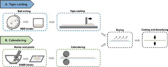
Figure 1. Schematic illustration of the thin solid electrolyte separator fabrication processes (A) tape-casting and (B) calendering. For tape-casting, the Li6PS5Cl, NBR, and toluene are mixed by planetary ball milling, and then the prepared slurry is coated on a silicone-coated polyester substrate. For calendering, the Li6PS5Cl, XNBR, and toluene are mixed using mortar and pestle, and then the formed 'rubbery' composite is calendered to a free-standing thin separator. After drying at room temperature for 12 h, the obtained thin SE separators by the two processing methods are cut and compressed under a uniaxial press (100 and 200 MPa).
Download figure:
Standard image High-resolution imageNBR is a commonly used binder for sulfide-based electrolytes. XNBR is a functionalized NBR, characterized by the addition of a polar functional group (–COOH). In addition to their similar chemical structures and comparable tensile moduli (2.15 and 1.55 MPa, respectively) [27, 28], NBR and XNBR were selected due to their solubility in toluene, a nonpolar solvent that has good chemical compatibility with sulfide LPSCl solid electrolyte. Moreover, choosing XNBR for calendering is due to its tendency to form a complex and 'rubbery' composite with LPSCl that enables calendering but prevents tape-casting, whereas NBR is selected for tape-casting because LPSCl and NBR can be mixed in toluene to form a tape-casting slurry [26]. For the component mixing in the tape-casting process, high-speed and high-energy ball milling is used, which could break down the large LPSCl particles and agglomerates, ensuring the uniform dispersion of materials in the T-TSEs and making it easier to control TSE thickness precisely in the following tape-casting step. Regarding the calendering process, the low-speed and low-energy mechanical mixing could reduce the damage to the LPSCl particles, which in turn decreases the resistance stemming from an increased number of particle interfaces and defects.
Figure 2 shows the influence of the densification on the cross-sectional microstructure of the samples with 5 wt.% binder content characterized by focused ion beam-scanning electron microscopy (FIB-SEM) and the corresponding porosities for the samples with both 5 and 10 wt.% binder contents.
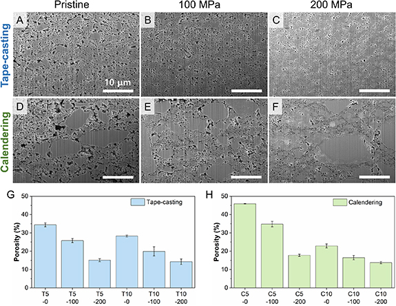
Figure 2. Cross-sectional SEM images of thin solid-electrolyte separators with 5 wt.% binder content prepared by (A)–(C) tape-casting and (D)–(F) calendering processes as a function of densification pressure (A) and (D) pristine, (B) and (E) 100 MPa and (C) and (F) 200 MPa. All the scale bars are 10 μm. Porosity of the thin solid electrolyte separators prepared by (G) tape-casting (T) and (H) calendering (C) processes as a function of densification pressure (0, 100, and 200 MPa denoted by X-0, X-100, and X-200, respectively) and binder content (5 or 10 wt.% denoted by X5 or X10, respectively).
Download figure:
Standard image High-resolution imageCompared to the pristine powder (figure S1), the LPSCl particles in C-TSEs maintain a similar morphology (figures 2(D)–(F)), with small particles < 3 μm in size and larger particles/agglomerates reaching sizes of 10 μm or more. However, the ball milling step for T-TSEs appears to have broken up these large LPSCl particles/agglomerates, resulting in a different morphology (figures 2(A)–(C)) with reduced particle size and an average particle size of ⩽ 2 μm. The reduction in size of the LPSCl particles can be mainly attributed to the high-energy mechanical mixing step involved in the slurry processing and partially due to the NBR binder functioning as a surfactant [12]. The packing of the LPSCl particles becomes much denser as the densification pressure increases. Figures 2(A) and (D) show loosely packed LPSCl particles with an interconnected open-pore network in the pristine T- and C-TSEs. After densification at 200 MPa, only isolated voids are left and parts of the LPSCl particles underwent plastic deformation to some extent that allowed them to aggregate into larger domains with indistinct boundaries between them (figures 2(C) and (F)).
As shown in figures 2(G) and (H), an increase in binder content or densification pressure leads to a reduction in porosity. The porosity of the TSEs with 10 wt.% binder is lower than the one with 5 wt.% binder at the same densification pressure, more significant for C-TSEs, as the binder can fill the voids between the particles. For the T-TSEs, the reduction in porosity with densification appears to follow an approximately linear trend from 0 to 200 MPa, however, this is not the case for the C-TSEs. Notably, there is a more pronounced reduction in porosity when going from C5-100 to C5-200 compared to that from C5-0 to C5-100, as well as going from C10-0 to C10-100. The above observation could be attributed to the more homogeneous microstructure in the T-TSEs compared to the C-TSEs, resulting in a more consistent and uniform densification process. Although a higher degree of densification (> 200 MPa) is expected to result in lower porosity and higher ionic conductivity [12], the resulting TSEs proved too brittle to allow meaningful tensile tests. This brittleness renders such high densification pressures undesirable for our investigation aimed at linking processing, microstructure, and the mechanical and electrochemical properties. Therefore, higher densification pressures are beyond the scope of this work.
The above results of the densification effect on porosity suggest a more homogeneous distribution of binder in the T-TSEs than the C-TSEs. Further, energy-dispersive x-ray spectroscopy (EDX) was performed on the T- and C-TSEs with 5 wt.% binder content after densification at 200 MPa (figures 3(A) and (B)). The sulfur and carbon signals were used to identify the LPSCl and the binder locations, respectively. The relatively homogeneous sulfur signal in both is as expected. The carbon distribution map gives a qualitative indication that the NBR binder within the T-TSEs is homogeneously wrapping the LPSCl particles, whereas in the C-TSEs the higher intensity of carbon signal in certain areas demonstrates random distribution or agglomeration of XNBR binder at the boundaries of LPSCl particles. This provides further evidence of the more homogeneous microstructure of the T-TSEs in terms of both particle size and binder distribution.
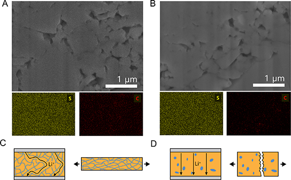
Figure 3. Magnified cross-sectional SEM images and EDX mapping results of polymer binder distribution in thin solid-electrolyte separators with 5 wt.% binder content prepared by (A) tape-casting and (B) calendering processes. Schematic illustration of the structures of the thin solid-electrolyte separators prepared by (C) tape-casting and (D) calendering processes along with the trade-off relationship between the mechanical and electrochemical properties.
Download figure:
Standard image High-resolution image2.2. Mechanical properties
Tensile testing is carried out under Ar atmosphere to understand the mechanical properties of the T- and C-TSEs. The recorded stress-strain curves for the corresponding T- and C-TSEs with different binder contents (5 and 10 wt.%) and densification pressures (0, 100, and 200 MPa) are shown in figures 4(A) and (B). There is a clear difference between the T- and C-TSEs. The stress-strain curves of T-TSEs present a steep linear-elastic region followed by a plateau in which the plastic elongation of the T-TSEs takes place. In comparison, the stress–strain curves of C-TSEs have a very different shape without clear yield points or elongation plateau.
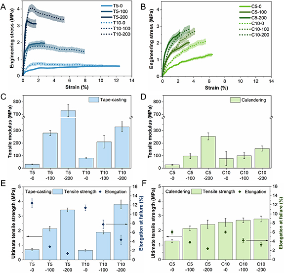
Figure 4. (A) and (B) Representative stress-strain profiles, (C) and (D) tensile modulus, (E) and (F) ultimate tensile strength and elongation at failure of the thin solid-electrolyte separators prepared by (A), (C) and (E) tape-casting (T) and (B), (D) and (F) calendering (C) processes as a function of densification pressure (0, 100, and 200 MPa denoted by X-0, X-100, and X-200, respectively) and binder content (5 or 10 wt.% denoted by X5 or X10, respectively). Error bars are presented as shaded areas around the curves.
Download figure:
Standard image High-resolution imageFor a quantified comparison, the tensile modulus and ultimate tensile strength (UTS) were determined from the stress-strain curves. For all the samples under investigation, the UTS was defined as the maximum stress before failure. Figures 4(C) and (D) show the tensile moduli of the tested samples. At the same binder content and densification pressure, T-TSEs with the more well-distributed binder network demonstrate a higher tensile modulus compared to the counterparts prepared by the calendering method with the binder partially covering LPSCl particles. Despite the porosities of the T5-200 and C5-200 or T10-200 and C10-200 samples are comparable, the tensile modulus of the T-TSEs is nearly twice that of the C-TSEs. Both T- and C-TSEs displayed an obvious increase in tensile modulus upon densification for both binder contents. For pristine TSEs higher tensile modulus values are observed with higher binder loadings, however, this effect is reversed after densification. The tensile modulus of the T5-200 and C5-200 are approximately double the values for their 10 wt.% counterparts.
Figures 4(E) and (F) show the UTS and elongation at failure of the tested samples. For T-TSEs, as the densification pressure increases, the UTS increases whereas the elongation at failure decreases. The binder content has a significant impact on the UTS and elongation at failure of the densified samples, with the elongation at failure more than doubling when going from 5 to 10 wt.% binder content for both the 100 and 200 MPa densified samples. For C-TSEs, the change in both UTS and elongation at failure with the densification and binder content is much less pronounced. Interestingly, the UTS of T- and C-TSEs are comparable to or higher than the reported values for dry-processed LPSCl-based SEs with a fibrous PTFE binder which possesses a significantly higher tensile strength than NBR or XNBR [21, 29, 30].
The above differences between the T- and C-TSEs could be due to the difference in the LPSCl particle size and binder distribution induced by processing. It has been shown in the literature that the difference in tensile modulus of ceramic-polymer composites is independent of the particle size, but rather depends on the adhesion between the two phases present and stress transfer between phases [31–33]. Therefore, the binder distribution must play the dominant role. As shown in figures 3(C) and (D), a more homogeneous distribution of binder surrounding the smaller LPSCl particles in the T-TSEs enables a more efficient transfer of local stresses between the LPSCl and binder, enhanced by the high adhesion between NBR and sulfide particles [32], which accounts for the higher tensile modulus, UTS, and failure strain in these systems. In comparison, the larger LPSCl particles and less well-dispersed XNBR binder in C-TSEs result in a reduced area for adhesion between the binder and LPSCl particles, leading to lower strain to failure, UTS, and tensile modulus.
From the above, it can be found that the difference in mechanical properties is strongly correlated with the microstructure achieved after the processing and densification. The change in microstructure due to densification significantly influences the mechanical properties in both the T- and C-TSEs, rendering them stiffer and less deformable. At the same binder content and densification pressure, it seems that the mechanical properties are more dependent on the binder distribution.
2.3. Electrochemical properties
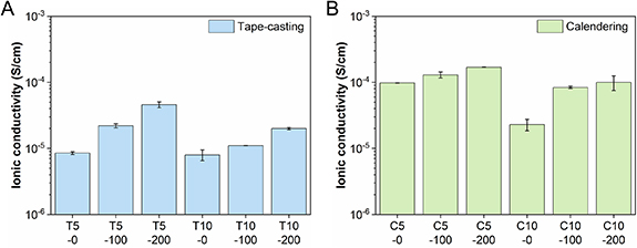
Lithium-ion conductivity is the other important property of a TSE. To evaluate this, EIS was performed using custom SSB testing cells under practical operating conditions (stack pressure of 2.5 MPa, 298 K). Figures 5(A) and (B) show the ionic conductivities of the T- and C-TSEs with different binder contents (5 and 10 wt.%) and densification pressures (0, 100, and 200 MPa).
Figure 5. Ionic conductivity of the thin solid-electrolyte separators prepared by (A) tape-casting (T) and (B) calendering (C) processes as a function of densification pressure (0, 100, and 200 MPa denoted by X-0, X-100, and X-200, respectively) and binder content (5 or 10 wt.% denoted by X5 or X10, respectively) measured by electrochemical impedance spectroscopy (EIS) under 2.5 MPa operating pressure.
Download figure:
Standard image High-resolution image
TSEs prepared using both processing methods were found to show improved ionic conductivities with lower binder contents and higher densification pressures. As the binder is non-ionically conductive and would cover parts of the LPSCl particles, a higher proportion of it would reduce the overall conductivity of the TSEs while also reducing the effective contact area between the LPSCl particles and increasing the tortuosity of the Li+ pathways [34]. On the other hand, the higher ionic conductivities with higher densification pressures arise from the reduced porosity, creating more ion-transport pathways and reducing the tortuosity across the TSEs.
Comparing the two processing methods, C-TSEs have significantly higher ionic conductivities. T-TSEs all show ionic conductivities below 10−4 S cm−1 with the highest coming from the T5-200 sample (4.6 × 10⁻⁵ S cm−1), whereas ionic conductivities close to 10−4 S cm−1 are obtained for C-TSEs with the highest one coming from the C5-200 sample (1.7 × 10⁻⁴ S cm−1). As we use a practical stack pressure of 2.5 MPa, the obtained ionic conductivities are lower than the theoretical value of LPSCl (∼1.0 × 10⁻³ S cm−1) and some other reported values for similar systems, which are usually measured using impractical stack pressures (e.g. > 20 MPa) [34].
Additionally, the ionic conductivities of the C-TSEs are less sensitive to the densification pressure increase than the counterparts of T-TSEs. Specifically, although the porosities of T-TSEs (T5-0, T5-100, and T5-200) are lower than C-TSEs (C5-0, C5-100, and C5-200), the ionic conductivities of C-TSEs are much higher, indicating other factors apart from porosity are the key. The higher ionic conductivities of the C-TSEs can be explained by the following: with the short mixing step in the calendering method, the LPSCl particles were subjected to much less time of the interaction between toluene and LPSCl, which has been observed to have a detrimental effect on the total ionic conductivity of LPSCl powders [35]. Without the high-energy mechanical mixing step used in the tape-casting method, larger LPSCl particles remained in the C-TSEs, which provide longer uninterrupted ion-transport pathways and less interfacial resistance between particles. The XNBR binder in the C-TSEs also tends to randomly distribute at the boundaries of LPSCl particles but does not form a thin insulating layer around the particles, providing fewer barriers and more continuous ion-transport pathways (figure 3(D)). From the above, it is found that the difference in conductivity is not only a function of the binder content but also relies on the SE particle size and binder distribution.
3. Conclusions
In summary, we have compared two practical processing methods which can be used to manufacture TSE separators. The processing of the LPSCl/binder composite has a clear impact on both the mechanical and electrochemical properties of the TSEs, with various microstructural features including particle size, binder content and distribution, and porosity (densification pressure) all playing important roles. TSEs prepared using the tape-casting method yield overall lower ionic conductivities but demonstrate superior tensile mechanical properties, including tensile modulus, tensile strength, and elongation at failure due to the more well-distributed but non-ionically conductive binder network, compared to TSEs prepared by the calendering method. In contrast, TSEs using the calendering method show much higher ionic conductivities but compromised tensile mechanical properties due to the remaining binder partially covering large LPSCl particles with longer undisturbed ionic pathways. The calendered TSE with 5 wt.% XNBR binder densified to 200 MPa is presented as a potential compromise between having an adequately high ionic conductivity for low internal resistance of the ASSB and acceptable mechanical properties for practical use of the separators. This work demonstrates the importance of understanding the processing-structure-property relationships in TSEs, which need further investigation to facilitate the practical manufacture and application of thin SEs.
4. Experimental methods
4.1. Materials
Li6PS5Cl (LPSCl) SE powder (99.9%, ∼10 μm, Ampcera Inc., density: 1.64 g cm−3), nitrile butadiene rubber (NBR, Krynac 3345F, Arlanxeo, density: 0.97 g cm−3), carboxylated nitrile butadiene rubber (XNBR, Krynac X750, Arlanxeo, density: 0.98 g cm−3) and anhydrous toluene (99.8%, Sigma Aldrich).
4.2. TSE separators preparation
For tape-casting TSEs, the slurries with three compositions (LPSCl and NBR at a weight ratio of 95:5, 90:10, and 80:20) were prepared. Firstly, 500 mg of NBR polymer was fully dissolved in 10 ml of anhydrous toluene. To prepare the slurry, LPSCl was weighed into a ball milling jar before the polymer solution was added. After ball milling for 30 min at 600 rpm in a planetary ball mill (Fritsch Pulverisette 7), the slurry was then coated on a silicone-coated polyester film using the doctor blade technique. After drying at room temperature for 12 h, the TSE was peeled off the substrate, cut, and compressed with stainless steel plungers (10 mm diameter) under a uniaxial press (100 and 200 MPa). The thickness of TSEs with 5 wt.% binder as a function of densification pressure (0, 100, and 200 MPa) is 117 ± 8, 113 ± 7, and 80 ± 5 µm respectively. The thickness of TSEs with 10 wt.% binder as a function of densification pressure (0, 100, and 200 MPa) is 82 ± 6, 75 ± 2, and 64 ± 3 µm respectively. All processes were carried out in an Ar-filled glove box (MBRAUN, MB 200B, H2O < 0.1 ppm, O2 < 0.1 ppm).
Calendered TSEs were prepared by previously reported procedures [26]. LPSCl powder and XNBR binder (5, 10 and 20 wt.%) were combined in anhydrous toluene and mixed using agate mortar and pestle or a vortex mixer for 3 min. The composite was placed between silicone-coated polyester films and calendered to a free-standing thin film. The thickness of the prepared TSE was controlled by setting the gap distance of the calendering machine's rollers (MTI Corp., MSK-2150). After drying at room temperature for 12 h, the TSE was cut and compressed with stainless steel plungers (10 mm diameter) under a uniaxial press (100 and 200 MPa). The thickness of TSEs with 5 wt.% binder as a function of densification pressure (0, 100, and 200 MPa) is 111 ± 11, 93 ± 9, and 97 ± 7 µm respectively. The thickness of TSEs with 10 wt.% binder as a function of densification pressure (0, 100, and 200 MPa) is 100 ± 15, 93 ± 3, and 70 ± 9 µm respectively. All processes were carried out in an Ar-filled glove box (MBRAUN, MB 200B, H2O < 0.1 ppm, O2 < 0.1 ppm).
4.3. Characterization
Porosity of the TSEs was determined using equation (1). Samples of the TSE were punched (10 mm diameter) and their weight (Sartorius Cubis II Ultra Micro Balance) and thickness (Mitutoyo, 293–344 External Micrometer) were measured. WTSE and VTSE are the weight and volume of the TSEs, respectively.
 a and ρa are the weight fraction and density of component a in the composite [26],

Tensile testing was performed using a DEBEN Microtest tensile, compression and horizontal bending stage (MT5000 Dual Leadscrew Tensile Tester H-550 Controller) equipped with a 1 kN load cell operating at 50× gain and with a digital extensometer. Experiments were visually monitored and recorded using a digital camera connected to the ThorCam software. Rectangular-shaped TSE specimens of fixed width and length (0.8 × 3.0 cm) were punched using a die cutter. Their thickness was individually evaluated using a digital screw micrometer gauge with 0.001 mm sensitivity and averaged from three different locations of the specimen. Carefully aligned TSEs were monotonically loaded in tension (extension rate = 1.0 mm min−1) while measuring the resulting force until rupture occurred. At least three specimens were tested for each composition to achieve statistical validation. All the handling and analyses have been carried out in an Ar-filled glove box (H2O < 0.1 ppm, O2 < 0.1 ppm) to avoid any possible degradation of the TSEs. Error bars on the stress-strain curves were computed as a relative error considering the average fluctuations in the force recorded by the DEBEN stage to account for the instrumental sensitivity in the employed force range.
Ionic conductivity of the SE (circular disk, 10 mm diameter) was measured by EIS using a VMP-3 potentiostat (Biologic, France) with a voltage amplitude of 10 mV in the frequency range of 1 MHz to 0.01 Hz with the cell-configuration (carbon-coated Al foil/SE/carbon-coated Al foil). The measurement was carried out using a custom-made battery testing cell under a stack pressure of ∼2.5 MPa at 298 K.
Microstructure characterization of the TSE was carried out using plasma focused ion beam scanning electron microscopy (PFIB-SEM) sectioning. PFIB sectioning was performed using a Thermo Fisher Helios G4-CXe Plasma-FIB. The samples were transferred to the PFIB using an airless transfer vessel (Gatan), then milled and polished using a constant voltage of 30 kV and a current down to 15 nA.
Acknowledgments
This work was supported by the Faraday Institution LiSTAR (Grant No. FIRG014) and SOLBAT (Grant No. FIRG026) programs and the Henry Royce Institute (through UK Engineering and Physical Science Research Council Grant No. EP/R010145/1) for capital equipment. The authors are grateful to Arlanxeo for providing the NBR and XNBR samples. Moreover, the authors express gratitude to Ed Darnbrough and Camilla Hurst for their contributions to optimizing the experimental setup for tensile testing.
Data availability statement
All data that support the findings of this study are included within the article (and any supplementary files).
Author contributions
Junhao Li, Lorenzo Mezzomo, and Soochan Kim: conceptualization, methodology, investigation, writing (original draft), reviewing, and editing. Yvonne Chart: writing, second draft, reviewing, and editing. Jack Aspinall: writing, reviewing, and editing. Riccardo Ruffo: conceptualization, methodology, writing, reviewing and editing, supervision, project administration, and funding acquisition. Mauro Pasta: conceptualization, methodology, writing, reviewing and editing, supervision, project administration, and funding acquisition.
Conflict of interest
The authors declare no competing interests.
Supplementary data (5.7 MB DOCX)