
Abstract
There is a growing consensus that future specific energy improvements in Li–ion batteries may not ever be sufficient to allow mass market adoption of electric vehicles, as we approach the physical limits of storage capacity of current Li–ion batteries. Several 'beyond li-ion' (BLI) chemistries are being explored as possible high-energy-density alternatives to Li–ion batteries. In this article, we focus on analyzing three BLI battery systems: Li–air, Li–sulphur and Na–air. We present a comprehensive discussion of the fundamental material challenges associated with these chemistries and document the progress being made in translating next-generation battery systems from the lab to the market. We also carry out a critical examination of the hype surrounding emerging battery technologies. We report, for the first time, a hype chart for batteries akin to those popularized by Gartner, Inc. for emerging technologies. We expect this hype chart to give us better insights on the respective standings of the current BLI technologies.
Export citation and abstract BibTeX RIS
1. Introduction
The electrification of road transport is a societal goal of utmost importance. There are several key factors driving this change: (i) a move to shift away from oil, which has often been a major source of political instability, (ii) an effort to curb CO2 emissions, one third of which is contributed by vehicular transportation, (iii) an attempt to improve air quality, especially in densely populated cities. Air quality concerns in major cities around the world are so alarming that it has led to a major push in emerging economies towards electric vehicle adoption in an effort to improve purity of breathable air and curb levels of particulate matter, especially the PM2.5 levels.
The major hurdle for widespread adoption of electric vehicles (EVs) was highlighted in a quote in the Washington Post, 'Prices on electric cars will continue to drop until they're within reach of the average family'. This quote was actually featured in the newspaper in 1915, and a century later, we are still facing the same issue. The main culprit here is the insufficient storage capacity of current batteries, severely limiting the range of practical EVs. The importance of developing better batteries for road transportation has been emphasized over the past few years, with several leading research programs emerging in the last 5 years. The aim of this article is to present a focused discussion of a few next-generation battery technologies that can meet these ambitious targets. The concepts and principles presented here are expected to be broadly useful in critically analyzing 'beyond Li–ion' battery chemistries.
1.1. Need for high-energy-density rechargeable batteries: beyond Li–ion
Over the past ∼5 years, an opinion has evolved that future specific energy improvements in Li–ion batteries may not ever be sufficient to allow for mass market adoption of EVs, as the amount of lithium that can be stored in optimized active cathodes and anodes is nearing physical limitations. As a result, several battery chemistries are being explored as possible high-energy-density alternatives to Li–ion batteries (the so-called 'beyond Li–ion' (BLI) chemistries). There are a number of competing BLI chemistries and in this work, we will focus on analyzing three systems, Li–air, Li–sulphur and Na–air.
This article will begin by introducing the three battery systems, followed by a critical examination of the hype surrounding emerging battery technologies. We report for the first time, a hype chart for batteries akin to those popularized by Gartner, Inc. for emerging technologies. This is followed by a discussion of the fundamental material challenges associated with these chemistries, and a documentation of the progress being made in translating next-generation battery systems from the lab to the market.
1.2. Battery design 1: lithium–air
The Li–air battery is an open-system high energy density battery. A typical Li–air cell consists of pure lithium metal as the anode, an organic electrolyte, and a carbon cathode. During the discharge process, lithium from the metal anode travels in the form of Li+ ions to the carbon cathode, where it reacts with the incoming oxygen to form lithium peroxide Li2O2 at a carbon binding site. The main discharge product, Li2O2, builds up in the form of nanometer sized thin layers, and also as toroids which are of micron size, as shown in figure 1(a). A typical galvanostatic plot for the Li–air chemistry, in figure 1(b), shows minor deviations from the average discharge potential  , but features a precipitous drop in voltage at the end of the discharge cycle often termed as 'sudden death'. During the charging process, there is significant increase in inefficiency owing to electrolyte degradation. Two major electrochemical routes for the discharge processes have been identified: the surface process and the solution process, as outlined in figure 1(c). In the surface process, lithium ions and oxygen combine with electrons at the carbon cathode, to eventually lead to the formation of crystalline Li2O2, as shown in blue in figure 1(c). In the solution process, the temporarily adsorbed
  is dissolved and the generated
  diffuses to an existing toroidal discharge feature or a fresh nucleation site, and leads to toroidal discharge product growth. When the insulating discharge product film becomes too thick to support the operational current, the battery shuts off, experiencing sudden death.

Figure 1. The lithium–air battery. (a) The main discharge product, Li2O2, building up as micron sized toroids. (b) The galvanostatic charge–discharge plot for the Li–air chemistry shows various losses during cycling. (c) Two major electrochemical routes for the discharge processes have been identified: the surface process and the solution process. (a) Discharge product. (b) Charge–discharge curve. (c) Major chemical processes.
Download figure:
Standard image High-resolution imageThe externally supplied oxygen at the cathode comes from the air handling unit, a processing unit that separates oxygen from air. During the charging process, the lithium peroxide layer is dissolved, and the free lithium ions migrate back to the lithium metal anode, where they are reduced and redeposited. The Li–air battery chemistry is described in the following reactions [1]:
At the anode:

At the cathode:

Current Li–ion batteries have a specific energy of approximately 100–200 Wh kg−1 [2]. The Li–air battery, being an open system, i.e. air-breathing, demonstrates a significantly higher specific energy than Li–ion batteries, which are closed systems in that they must pack in the active ingredients. The carbon based cathodes in Li–air battery are lighter than the intercalation material based cathodes of Li–ion batteries, and thus, the Li–air system has a significantly higher specific energy. The Li–air design offers a practically achievable specific energy of approximately 1.0 kWh kg−1 [3], which is comparable to the specific energy of gasoline, approximately 1.7 kWh kg−1 [4].
It is important to realize that Li–air batteries need an accompanying air handling system to separate the O2 from atmospheric components, such as CO2, dust, and water, which are detrimental to battery operation. While such systems exist for industrial applications, the specific challenge in electrical vehicle context is the need for an efficient and lightweight air handling system that delivers pure O2 at sufficient rates. Lithium is the economically limiting raw material for the Li–air battery system. Elemental lithium is relatively abundant on earth, occurring in many mineral compounds, with a global distribution estimated to be around 28–39 million tons, but only 10–13 million tons are considered to be economically extractable [5]. Currently, the world lithium production is around 36 thousand tons/year, and is expected to increase significantly in the coming years. The costs of the lithium metal as anode material is not expected to form a significant part of the total battery costs [6].
The Li–air battery is still in the phase of early laboratory development. However, to realize practicable Li–air batteries, certain materials issues must be solved to allow for sufficiently high discharge capacities and adequate rechargeability at practical current densities. These issues include degradation of the electrolyte, stability of the cathode, and formation of dendrites at the anode.
1.3. Battery design 2: lithium–sulfur
The lithium–sulfur (Li–S) battery is a closed high energy density battery system, which does not depend on any external material supply, unlike the Li–air and Na–air chemistries. The Li–S cell is usually composed of a lithium metal anode, an organic electrolyte, and sulfur composite cathode. During the discharge reaction, lithium metal is oxidized at the anode, releasing lithium ions, which are transported across the electrolyte to the cathode, as given by:

The discharge process at the cathode begins with the opening of the cyclo-S8 ring upon reduction, as shown schematically in figure 2(c). This leads to the formation of high-order Li–S polysulfides of various moieties, marked by the region I in the galvanostatic discharge-charge plateau in figure 2(b). This plateau has an equilibrium potential of  V versus Li/Li+ electrode. Upon continuation of the discharge process, the higher-order polysulfides are reduced to intermediate and lower-order polysulfides, marked by region II, which has an equilibrium potential of
  V versus Li/Li+ electrode. In real systems, regions I and II overlap each other. The overall reaction of sulfur reduction for producing lithium sulfide (Li2S) upon lithium ions and electrons is given by:

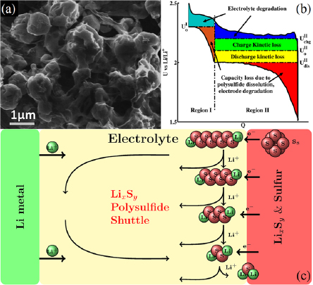
Figure 2. The lithium–sulfur battery. (a) High-magnification SEM image [7] of a graphene–sulfur composite cathode. (b) The galvanosttic charge–discharge plot for the Li–S battery chemistry, showing various losses. (c) Schematic showing the dissolution of the intermediate polysulfides in the electrolyte and their migration to the anode, where they are reduced to lower order polysulfides. These then migrate back to the cathode, where they are converted to higher order polysulfides again. (a) Discharge product. (b) Charge–discharge curve. (c) Major chemical processes.
Download figure:
Standard image High-resolution imageDuring the charging reaction, sulfur in Li2S is oxidized, and releases the lithium ions back into the electrolyte, which travel back to the anode to meet the externally fed electrons. Based on these electrochemical reactions, the Li–S cell has a theoretical capacity of 1.167 Ah g−1 [8]. The average voltage of the discharge reaction is 2.15 V, which translates to a theoretical gravimetric energy density of ∼2500 Wh kg−1 or a volumetric energy density of 2800 Wh L−1 [9–11]. While the challenges associated with obtaining metallic lithium remain the same as in the Li–air cell, sulfur is one of the most abundant elements on earth, with excellent geographic distribution, and is not environmentally toxic [12]. The prices for sulfur globally range from $60–$100 ton−1, indicating that it is extremely inexpensive to obtain sulfur [13]. Battery grade pure sulfur is estimated to cost around $220 ton−1, which is still quite inexpensive [14].
Although the Li–S chemistry can potentially lead to the desired high energy density rechargeable battery, several major challenges need to be overcome before the battery can be employed in practical applications. The issues observed in the Li–S battery are associated with large volume changes during cycling, limited cycle life, the insulating nature of both sulphur and Li2S, and low efficiency due to dissolution and migration of lithium polysulfides, as shown schematically in figure 2(c), which leads to a lowering of the Coulombic efficiency of the battery [15, 16].
1.4. Battery design 3: sodium–air
The Na–air battery is a very recent development with the first major report of this battery published in 2012 [18]. The maximum theoretically achievable specific energy for the Na–air battery has been reported as 1105 Wh kg−1 for NaO2 discharge product, and 1602 Wh kg−1 for Na2O2 discharge product [17]. This is a significantly lower theoretical specific energy than the 3458 Wh kg−1 reported for idealized Li–air cells with Li2O2 discharge product [18], but is also significantly higher than currently available lithium–ion intercalation-based batteries, like the LiCoO2 and LiFePO4 cells [17].
During the dischrage, at the anode, sodium ions are produced from the oxidation of sodium metal, given by,

The sodium ion then travels to the surface of the carbon cathode, where it reacts with an O2 molecule forming sodium superoxide as the main discharge product in form of cubic crystals, as shown in figure 3(a), according to the reaction,


Figure 3. The sodium–air battery. (a) The discharge product forms cubic crystals [17] of sodium superoxide, NaO2, with an edge length on the order of microns. (b) The galvanostatic charge–discharge plot shows minor deviations open circuit potentials for most of the cycle and the associated losses. (c) Two major electrochemical processes have been identified in this battery: the surface process and the solution process. (a) Discharge product. (b) Charge–discharge curve. (c) Major chemical processes.
Download figure:
Standard image High-resolution imageThe galvanostatic charge–discharge plot for this battery, as shown in figure 3(b), features a precipitous drop in voltage at the end of discharge, and an abrupt rise in voltage at the end of charge. Two major electrochemical processes have been identified in this battery: the surface process and the solution process, as outlined in figure 3(c). The surface process temporarily adsorbs a sodium ion and an oxygen molecule on the carbon cathode, to ultimately transfer an electron to the oxygen molecule, transforming it into a superoxide radical. The solution process re-adsorbs the superoxide radical, together with a new sodium ion, on the surface of a cubic discharge product crystal of NaO2.
The Na–air battery has a much lower theoretical energy density than the Li–air battery, so it may seem to be a less promising development to pursue. However, it has promise in the long-term, as sodium is far more abundant than lithium, and its yearly production is far greater [19]. Sodium is also attractive in the short-term economy due to its geographical distribution and comparatively lower price of purification. The availability and ease of access are strongly reflected in the bulk purchase prices of the two metals. The current price for bulk lithium metal is quoted at over $5000–$6000 per ton, while the bulk sodium metal price is under $440 per ton [20, 21].
2. Beyond lithium–ion: current state of affairs
2.1. The hype cycle
The categorization of emerging technologies is a challenging task. The hype cycle chart developed by the Gartner, Inc. advisory firm [22] has served as an important guide to calibrate the development and maturity status of emerging technologies. It comprises of 5 major phases of development, as shown in figure 6. The first phase is the Innovation Trigger, which begins when a new invention or breakthrough makes a technology immensely promising, and there is a high level of interest both from the media and the scientific community. Eventually, the technology's popularity reaches a peak, as failures begin to outweigh the initial seemingly promising successes. This phase is known as the peak of inflated expectations. As the technology development continues, more difficulties are encountered and there is a growing sense of discouragement about the merits of the technology. Consequently, it falls out of favor in the public view because of its failure to live up to the initial promises and the technology is now in the Trough of Disillusionment. It is possible that at this stage, some technologies will become obsolete because they will be surpassed by better competing solutions aimed at the same challenges. However, a small group of researchers may continue to work on further development and eventually find solutions to the problems that had been plaguing earlier efforts, thus bringing the technology to the slope of enlightenment. Now, the technology is ready for application and more researchers join the development and optimization period. Eventually, through industrial involvement and continued research, the technology may become widely accepted, and reach the plateau of productivity. This is the last phase accounted for in the Gartner hype chart, and is assumed to be the phase the technology occupies until it is supplanted by something better that can take over its market niche.
To identify the position of BLI chemistries in the hype cycle chart, we made extensive use of the year-by-year publication statistics for each of these BLI battery chemistries from the Thomson Reuters web of knowledge [23], as shown in figure 5 and table A1. Complete search queries and data are provided in the supporting information. A characteristic plot of publication history over the years is presented for the Li–ion battery in figure 4. We fit an exponential function to this data:  . In this scheme, the exponential growth coefficient a is the relevant metric to compare the publication rate of various batteries, while coefficient b is effectively a normalizing parameter, depending on how many papers were published in total. Because the Li–ion battery is so widely used today, it is safe to assume that it has gone through all of the phases in the hype Chart, and thus we can use its history as a base case example for this analysis. We identify two distinct regions in the available publication history, with distinct fitting parameters a. The first region shown in blue with a = 0.184 can be attributed to the earlier years of development, 1996–2006. This early phase can be identified as the region leading up to the peak of inflated expectations. We do not identify an initial Innovation Trigger in this timeframe, as is to be expected. After the initial exponential growth, there are several years where the publication rate flatlines, which could be loosely identify as a trough of disillusionment in the development of the Li–ion battery. There is no widespread additional interest for the battery seen in these years in the scientific community. However, around 2009, the publication rate again begins to increase exponentially, with an even higher growth coefficient of 0.333, almost double that of the initial phase. Judging from the higher growth coefficient, and its onset after a flatline period, we identify this second exponential as the slope of enlightenment leading into the Plateau of Productivity.
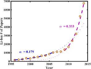
Figure 4. Number of papers about the Li–ion battery published each year between 1996 and 2014. Two distinct trends can be identified, separated by a flat-line region lasting several years. The first exponential region has a fitted growth exponent of 0.184, compared with the second region's growth exponent of 0.333. The faster exponential growth of the second phase is identified as indicative of the Plateau of Productivity.
Download figure:
Standard image High-resolution image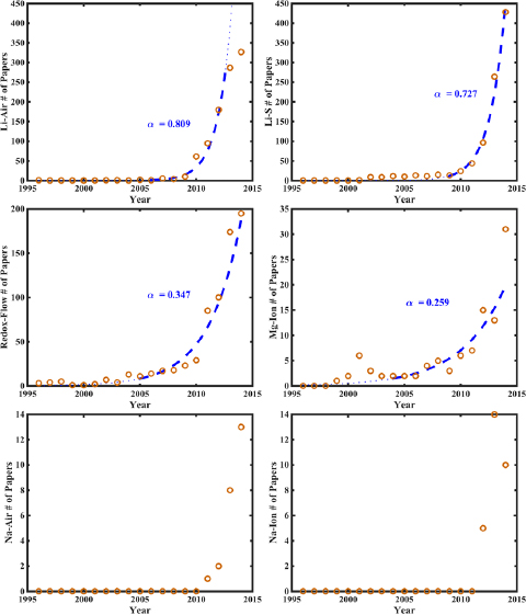
Figure 5. Number of papers published each year on the six different beyond-lithium–ion battery chemistries between 1996 and 2014, plotted as a function of the year. The years relevant to the exponential fit, marked by the thick, dashed lines, as well as the growth exponents for the different batteries, are specified. Li–S: 2009–2014, 0.73. Li–air: 2006–2013, 0.81. Redox-flow: 2005–2014, 0.35. Mg–ion: 2004–2014, 0.26
Download figure:
Standard image High-resolution imageThe same analysis was applied to a number of other battery chemistries, and their fitted growth exponents, a, as well as hype chart positions were estimated, as shown in table 1. Some chemistries do not yet have sufficient publication history, being extremely novel developments and they are placed in the Innovation Trigger phase. An important distinction to make here is that the analysis of the publication statistics for the BLI chemistries has been done in order to understand the variation in the growth exponents, dependent on the amount of research carried out in each of these. The representations of publication statistics in figure 5 for each of these BLI chemistries are not intended to be compared with the hype cycle by themselves alone.
Table 1. Fitted growth exponents for selected market and prospective rechargeable batteries.
| Chemistry | Growth exponent | Hype phase |
|---|---|---|
| Li–ion | 0.33 | Plateau of productivity |
| Li–air | 0.81 | Trough of disillusionment |
| Li–sulphur | 0.73 | Peak of inflated expectations |
| Redox-flow | 0.35 | Innovation trigger |
| Peak of Inflated expectations | ||
| Mg–ion | 0.26 | Innovation trigger |
| Na–air | — | Innovation trigger |
| Na–ion | — | Innovation trigger |
From the data presented in the table, we can identify a number of critical points. The rate of publication after the trough of disillusionment is higher than before for a given technology. The individual rates of publication differ from battery to battery, and appear to depend on the battery's promise of economic return on the invested research: the Li–air battery offers the highest theoretical energy density currently known, and its pre-trough publication rate is even higher than the Li–ion battery's post-trough publication rate. The pre-trough publication rates for other batteries, such as Li–sulphur, are likewise higher than that for Li–ion. We believe this is due to the fact that the Li–ion battery was in many ways the first of its kind of marketable high-energy-density rechargeable battery. Once the principle had been demonstrated as economically feasible and profitable in the mass market, researchers began to pay closer attention to novel chemistries, and thus their growth exponentials are significantly higher. Based on this analysis, we develop a qualitative version of the hype cycle chart placing the various batteries technologies according to the fitted growth exponents and is shown in figure 6.
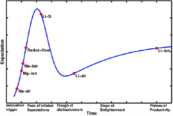
Figure 6. Gartner type hype chart for battery technologies. A typical technology goes through five phases: (i) innovation trigger, (ii) peak of inflated expectations, (iii) trough of disillusionment, (iv) slope of enlightenment and (v) plateau of productivity. Na–air, Mg–ion, Na–ion and redox-flow batteries are still in the innovation trigger phase. Li–S and Li–air have moved past the innovation trigger and it is still debated which one of the two will emerge as a practical battery. Li–ion batteries are well into the plateau of productivity, with the costs of these cells decreasing substantially.
Download figure:
Standard image High-resolution imageIn order to develop a more quantitative framework for the hype chart, meta-analysis was done on the published papers, to study the relationship between the growth exponent and the overall number of published papers on a specific battery. The highest exponents were found for battery chemistries with just over 900 publications: Li–air, with 971 publications and a growth exponent of 0.809, and Li–S, with 949 publications and a growth exponent of 0.727. Chemistries with lower numbers of publications were found to have lower growth exponents: for instance, the redox-Flow battery has 694 publications, and its growth exponent is just 0.347. The magnesium–ion battery yielded a tolerable fit with a growth exponent of 0.238, but as it only has 92 publications as of the end of 2014, indicating that the fit value may not be truly characteristic. The Li–ion battery, with over 28 000 publications, also has a lower growth exponent, at 0.333, but as mentioned earlier, its innovation trigger exponent was even lower than that, at 0.184. This forms a quantitative version of the hype chart and is shown in figure 7 and the conclusions remain largely similar to those found in our qualitative analysis. Note that in this plot, the growth exponent for Li–air is that of 2013, and hence it appears that it is near the peak of inflated expectations. It is important to note here that in this quantitative version, the chart was fit to the data and not the other way round. The similar placement of different BLI chemistries in the quantitative version of the hype chart in figure 7 valiadtes the qualitative version of the hype chart as shown in figure 6.
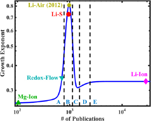
Figure 7. Growth exponent plotted as a function of the number of published papers in each type of battery. Five distinct regions are identified, which correspond to the five phases of the hype cycle: A is the innovation trigger phase, B is the peak of inflated expectations, C is the trough of Disillusionment, D is the slope of enlightenment, and E is the plateau of productivity.
Download figure:
Standard image High-resolution image3. Battery development: fundamental materials challenges
The three battery designs described above currently remain largely a subject of laboratory research due to a number of yet unsolved issues regarding the specific electrode and electrolyte materials used. Most of these material problems are specific to each individual battery type, but a few are common to all designs. One such particular widespread problem is the formation of dendrites, common to all metal–anode batteries.
When the battery is recharged, metal ions are drawn back to the source anode where they are typically not re-deposited back in an orderly, flat, smooth arrangement. Instead, the incoming ions selectively redeposit on specific nucleation and growth sites, and grow out in form of long, branching filaments from those sites. These filaments, or dendrites, are very damaging to the battery because they can compress, deform, and push away the separator between the anode and cathode. This increases the effective anode–cathode separation, places the cell electrodes out of parallel alignment and damages the separator surface. Furthermore, the dendrites can pierce into the separator, thus causing extensive internal structural damage, and if left unchecked they can grow all the way through the separator and reach the cathode, which can result in a lethal short-circuit within the battery.
The underlying mechanics of dendrite formation and growth are not well understood and no practical solutions to avoid dendrite growth exist. A number of solutions have been proposed to avert the damage the dendrites inflict, if their formation proves to be unavoidable for a pure-metal anode of any geometry [24]. One promising solution in this area is to protect the anode side of the separator with an engineered material which would conduct the metal ions, but have sufficient mechanical hardness to block the growth of dendrites [25].
3.1. Lithium–air battery
3.1.1. Rechargeability
Rechargeability over a large number of cycles is required for high overall efficiency. The best Li–air cells today are only rechargeable over a few cycles, and can be operated only at low current rates [26–29]. Rechargeability is affected by multiple concurrent phenomena, such electrolyte decomposition, and the degradation and passivation of the electrodes [30].
Low rechargeability of Li–air batteries is characterized by rapidly increasing overpotentials during cycling, which ultimately reduce the battery's Coulombic efficiency, and passivation of the electrodes by electrolyte decomposition and carbonate formation, which limits the number of cycles due to an increasingly reduced cathode surface area upon cycling. The two effects are closely related to each other because the passivation of the cathode occurs partly due to electrolyte decomposition. Similar electrolyte decomposition at the anode, leading to SEI formation, also contributes to the overpotential increase.
In the nonaqueous Li–air battery, the electrolyte suffers electrochemical and chemical degradation in the environment of Li2O2, and forms insoluble fluorides, carbonates, alkyl carbonates, and other species [2]. The highest occupied molecular orbital (HOMO) level was identified as the key descriptor for the oxidative stability of non-aqueous solvents [31], with a deeper HOMO level of the solvent indicating better resistance against oxidative degradation. Additionally, solvated  anions are known to induce proton/hydrogen abstraction from nonaqueous solvents, which are generally weakly acidic, through a nucleophilic attack process. This severely undermines solvent stability in the battery [32]. It has been shown that the propensity of a solvent to resist proton/hydrogen abstraction, via nucleophilic attack or electrochemical adsorption at the surface, is dependent on its acid dissociation constant, pKa, in its own environment [33]. The higher the pKa, the higher the resistance of the solvent against proton/hydrogen abstraction. However, it has been found that most solvents obey an anticorrelation between the HOMO level and the pKa of a solvent [33]. This implies that a solvent with higher pKa, which implies more stability against proton/hydrogen abstraction, will also have a higher HOMO level, implying more susceptibility towards oxidative degradation. Thus, the ideal solvents desired must be anomalies to this fundamental trade-off between oxidative stability and proton/hydrogen abstraction.
In the early years, carbonate-based solvents were widely investigated with salts like LiPF6 and these solvents are unstable and form insoluble Li2CO3 during discharge instead of the cyclable Li2O2, resulting in loss of active components [34, 35]. Ethers and glymes are more stable, have low volatility and low polarity. However, ethers and glymes wet the carbon cathode to reduce the O2 transport, and also decompose to form Li2CO3, HCO2Li, CO2, and H2O [36–38]. Ionic liquids have been proposed as strong candidates for the role of electrolytes, due to their low vapour pressure, high ionic conductivity, wide electrochemical window and stability against  [39–41]. Ionic liquids of the piperidinium and pyrrolidinium families have demonstrated excellent lithium metal cyclability [42]. To avoid problems associated with volatility and electrochemical stability of liquid electrolytes, solid electrolytes based on ceramics and solid polymers have also been explored [43–45]. However, their rechargeability has not been demonstrated.
There is a large number of constraints on the electrolytes needed for the practical Li–air battery. The electrolyte must be stable in the electrochemical environment, must be able to withstand temperature fluctuations, dissolve O2, have high ionic conductivity, and resist degradation via the various mechanisms described above. It is a formidable task to find an electrolyte which simultaneously satisfies all these requirements. To enable the discovery of such electrolytes, several groups have developed a large database of electrolytes with all the relevant properties. These databases can be easily queried, and will help researchers not only discover better electrolytes, but also discover various trends in electrolyte properties. A broader search for the ideal electrolyte includes electrolyte mixtures, as their combined properties and interaction with each other can produce novel behavior, not possible in pure electrolytes.
Another major challenge with the development of materials for the Li–air battery is to find suitable electrode materials. The highly investigated graphite cathodes are a major source of carbon that form lithium carbonates. These carbonates deposit over the cathode and inhibit charge transport, which causes an increase in the overpotentials, and in turn significantly reduces the efficiency of the battery [30]. Various metal oxides of Mn, Fe, Cu, Pd, Ru, Ir have been explored to search for materials that possess better rechargeability [46–49].
3.1.2. Deep discharge
The Li–air battery, as it stands today, cannot be fully discharged to the extent of its theoretical energy density. The primary reason for this limitation is the formation of the insulating, insoluble discharge product Li2O2 in form of thin passivating layers over the cathode, thus shutting off the charge transport. Pore blockage by lithium oxides and other parasitic products at the beginning of the discharge limit the O2 transport at the cathode could also limit the battery capacity.
To produce innovative, functional designs that would prevent electrode passivation and pore blocking, it is important to know the ways in which the cathode microstructure affects discharge performance. Hence, it is necessary to characterize the porous structure of the cathode and relate it to observed electrochemical performance. One solution is to use nanostrucured materials like graphene, nanotubes, foams, and nanofibres, to increase the surface area and lower the charge transfer resistance [50, 51]. However, just increasing the surface area is not sufficient to achieve higher capacity. The cathode structure should also be highly porous, with pore sizes larger than 20 nm to be able to sustain O2 mass transport [52]. Mesoporous carbon-cathode based Li–air batteries have been shown to have a significantly higher capacity [53, 54].
At higher currents, the capacity is limited by O2 transport. It is dependent on solubility of O2 in the electrolyte and its diffusion in the electrode microstructure. O2 solubility in inorganic solvents is low but it can be enhanced by choosing appropriate salts [55, 56]. The transport of O2 can also be enhanced by creating gas diffusion channels in the cathode microstructure [57].
Another potential solution to improve battery discharge capacity is to use electrolytes that dissolve the insulating Li2O2 film, and re-deposit the compound to form large toroidal deposits by themselves, in the absence of a passivating film [58]. This solution process can be activated by either choosing an electrolyte with a high Gutmann donor number (DN), to stabilize the Li+ , or an additive with a high acceptor number (AN), like H2O, to stabilize  . It has already been shown that choosing a high-DN solvent results in increased discharge capacity [59]. However, activating the solution process results in an increase in the formation of
  , which leads to H-abstraction, as discussed above. Thus, there exists a trade-off between rechargeability and discharge capacity, as has been explained recently [32]. Increasing the DN of the electrolyte also stabilizes dissolved Li+ , by forming solvation complexes. The formation of these bulky solvation complexes may decrease the ionic mobility of Li+ , which might limit the maximum achievable operating current. Although the solution process leads to an increase in capacity, it is rate-limited by the diffusion of
  , and hence the increase in capacity will only happen at low current densities [58]. The challenge of improving the discharge capacity at higher currents, without affecting the rechargeability of the battery, still remains an open question.
3.2. Lithium-sulphur battery
3.2.1. Polysulfide dissolution
Sulfur exists as homoatomic rings of various sizes, the orthorhomibic α—S8 being its most stable allotrope at room temperature [60]. The desired end product of the discharge reaction, Li2S, forms as a result of a series of reactions which begin with the opening of the cyclo-S8 ring upon reduction. This leads to the formation of high-order Li–S polysulfides of various moieties [12, 61]. Upon continuation of the discharge process, the higher-order polysulfides are reduced to intermediate and lower-order polysulfides (e.g. Li2S2) as given by:


One of the fundamental issues plaguing Li–S batteries is the decay in capacity contributed by the solubility of high-order polysulfides Li2Sx (6 < x <= 8), in several organic liquid electrolytes [11, 62]. After their dissolution, these intermediate polysulfides have been found to migrate to and react with the lithium metal anode to form low-order polysulfides, which then migrate back to the cathode and form high-order polysulfides again. This process effectively works as an internal redox 'shuttle', which lowers the Coulombic efficiency of the cell [63], and leads to (i) a severe loss of active material in the cathode and (ii) lithium corrosion in the anode [61].
A critical result of polysulfide dissolution is also the problem of self-discharge. Practical energy storage devices must posses low self-discharge characteristics, which serve as a marker of high Couloumbic efficiency. Li–S batteries, however, are known to demonstrate a high degree of self-discharge, like conventional batteries. This is due to the continuous and slow dissolution of higher order polysulfides in nonaqueous electrolytes in the system, even in the resting state, because of the presence of gradients in the chemical potential of the active material. This process leads to severe loss of the active material from the cathode, and eventually results in a lowered open-circuit voltage and decreased discharge capacity. Moreover, the diffusion of the dissolved material outside of the cathode region renders it permanently unusable. The amount of self-discharge has been found to depend on the type of current collectors employed in the system [64], necessitating the search for better current collectors at the electrodes.
In recent years, researchers have attempted to improve the utilization and cycling life of active materials by adding additives into the electrolytes. Using LiNO3 as an additive, it has been shown to improve the performance of Li–S batteries [65]. LiNO3 was found to react with the electrolyte, and lithium polysulfides have been found to form a protective passivation layer on the surface of the lithium anode. Another additive, P2S5, was found to promote dissolution of polysulfides, and at the same time, passivate the lithium metal surface. This yielded a structure that was conductive for lithium ions, but prevented the access of polysulfides to metallic lithium [66]. Adding Li–S polysulfides themselves to the organic electrolyte has been found to limit their migration from the cathode, due to the common-ion effect [12].
Another popular approach to suppress the shuttle mechanism is the encapsulation of the polysulfides within the cathode structure. Encapsulation of sulfur into hierarchically porous carbon nanoplates, and microporous carbon polyhedrons derived from a metal-organic framework, has been reported to exhibit improved specific capacities and rechargeability [67–69]. Additionally, polymer materials such as sulphur-polypyrrole, -polyaniline, and -polyacrylonitrile composites, have been developed, with the target of reducing dissolution and the shuttle effect of polysulfides, as well as improving electronic conductivity [70–72].
3.2.2. Insulating sulphur cathode
The insulating nature of both sulphur and Li2S necessitates the inclusion of conductive additives and binder materials into the electrodes, so that the derived structures can shorten the transport pathway for both ions and electrons during prolonged cycling. Sulphur encapsulated into hierarchically porous carbon has been shown to have good conductivity, with porous channels effectively adsorbing the active materials through physical adsorption. This leads to improved performance of Li–S batteries [67, 73, 74]. Conducting polymers are also known to form facilitating coating layers, which demonstrate optimum electrochemical performance [72, 75].
3.2.3. Massive volumetric changes
The conversion reaction during electrochemical discharge in the Li–S battery is accompanied by unfavourable morphological changes in the cathode that lead to volumetric changes of approximately 80% [8]. Due to the stresses induced by such large volume changes, this leads to an unstable electrode morphology, which is extremely detrimental for long term cycling. Therefore, flexible and robust conductive matrices are indispensable to accommodate the Li–S discharge products. Several modifications to the cathode material have been proposed to absorb the strain from cycling-induced volume changes. Graphene and graphene-oxide based materials with high surface area, superior electronic conductivity, high mechanical strength, and flexibility, have been found to be suitable to confine the polysulfides, accommodate the volume changes during discharge, and provide stable cycling [7, 76]. Apart from these, sulphur–metal–oxide core–shell and yolk–shell materials have also been devised, to provide extra void space to cushion the volume expansion of the active material. Such a solution would allow the battery to retain its structural integrity, and also assist with the retention of polysulfides [77, 78], although sulphur loading in such materials needs to be increased for practical applications.
3.2.4. Electrolyte stability
The primary functions of electrolytes in the Li–S battery are to efficiently transport lithium ions between the electrodes and protect the metallic lithium anode, through the formation of a lithium ion conductive solid electrolyte interphase (SEI). At the same time, it is required that the electrolyte is physically and chemically stable under the operating temprature and pressure, and also electrochemically stable within the working voltage window. The electrolyte has a critical effect on the discharge reaction mechanisms and the solubility of the formed products. Several electrolyte schemes have been applied to Li–S batteries, such as ether- and carbonate-based organic electrolytes [62, 79], ionic-liquid-based electrolytes [80], and polymeric and non-polymeric solid electrolytes [61, 81].
While an immense amount of effort has been invested in the design of new cathodes, in order to counter the insulating nature of sulphur and accommodate massive volumetric changes, the other longstanding problem, the dissolution of polysulfides, can be addressed by electrolyte engineering. A particular advantage of liquid electrolytes is that an optimum balance of desired properties can be achieved by taking various blends of solvents, salts and electrolyte additives, and combining them in a synergistic manner. Chain-ether-based liquid solvents, such as dimethoxyethane (DME), polyethylene glycol dimethyl ethers (PEGDME), and tetraethylene glycol dimethyl ether (TEGDME), have been the most commonly used solvents, due to their inhibition of polysulfide dissolution, high ion conductivity, low viscosity, and good wettability [82, 83]. At the same time, lithium salts in the electrolyte require expeditious solubility, a high degree of dissociation, and good compatibility with the liquid electrolyte. Salts such as LiTFSI and LiTf have been the most popular, due to their thermal stability and high dissociability [81]. The emergence of solid electrolytes has shown promise as the next breakthrough in electrolyte systems, largely by eliminating the polysulfide shuttle mechanism, and making the battery intrinsically safer; however, a number of challenges regarding ionic conductivity, efficiency of the discharge mechanism, and interfacial resistance, need to be solved [61, 81].
3.3. Sodium–air battery
3.3.1. Rechargeability
The most severe drawback faced by current Na–air battery is that they generally exhibit poor capacity retention upon cycling [17, 18, 84]. This issue is believed to be primarily caused by the properties of the battery's discharge product, sodium superoxide (NaO2) [17]. Typical rechargeable batteries, such as the Li–air battery, form a thin film of discharge product on the cathode, just a few nanometers in thickness. Such a film covers much of the cathode's available area, and has few large features, unless operated at exceedingly low currents, at which point large, 3-dimensional features of the order of microns start to appear [58]. In the Na–air battery, on the other hand, the discharge product builds up in the form of very large localized cubes of sodium superoxide, which have been observed to reach sizes as large as 50 microns on a side, with no film-like discharge product observed at all. This is markedly different behavior from that of the Li–air battery, both in the pattern of deposition and the stoichiometry of deposition: Li2O2 versus NaO2. Preliminary suggestions to explain this difference relate the energies of formation of nanoscale Na2O2 and NaO2, but a significantly more in-depth study of this is necessary [85].
The mechanism of the growth process of these large crystals is not fully understood. Recently, it has been suggested that the major mechanism responsible for both the growth and dissolution of the NaO2 crystals is phase-transfer catalysis, akin to the solution process, where in  anions are transported being bound temporarily in a HO2 unit, where the H+ proton is donated by the electrolyte [86]. It has been observed that upon cycling, the cubic crystals of NaO2 do not decompose completely, but prefer to dissolve only at the corners and edges and the charging overpotential increases steadily.
3.3.2. Electrolyte decomposition
Another major issue concerning Na–air battery development is closely related to the first issue of rechargeability. The decomposition of the electrolyte and salt start to occur at high recharging voltages, which are required to decompose the discharge product. This decomposition leads to the formation of passivating compounds which are harmful to the battery, including various carbonates and complex molecules containing fluorine and sulphur when sodium triflate (NaSO3CF3) was used as the salt [17]. These compounds formed due to parasitic reactions have been observed to coat the remaining discharge product crystals as thick, wispy, impenetrable layers, with measured thicknesses on the order of microns, which decrease the battery's ability to successfully be cycled by shielding the remaining NaO2 from external electrochemical reactions. This shielding effectively passivates the entire cathode, cutting off both the open carbon cathode, as well as the remaining undissolved NaO2 cubes [17]. These parasitic processes lower the Coulombic efficiency of the battery.
There exists a similarity between the insulating deposits in the Na–air battery and the carbonate formation in the Li–air battery. Both are mainly caused by electrolyte decomposition, and both eventually form impenetrable and insulating deposits that inhibits subsequent battery cycling. Whereas in the Li–air battery the carbonates form largely uniform and featureless layers, the insulating deposits on the Na–air discharge product crystals have a pronounced, disordered, wispy structure. It has also been found in measurements that while the Na–air battery produces negligible amounts of carbonates during the charge cycle, it produces a larger amount of carbonates during the discharge cycle, when compared with the Li–air battery [87]. The exact mechanism of formation of these complex deposits is not well understood, and is an important issue that needs to be solved, if the Na–air battery is to be developed into a practicable system.
4. Battery development: production and scale-up issues
4.1. Materials abundance
To adequately quantify the economic footprint of these new battery technologies, it is important to account for the fact that some of the materials used in the batteries are relatively scarce, or very costly to purify up to the required standards. Furthermore, both anode metals, lithium and sodium, are highly reactive and require the use of expensive packaging and handling equipment and methods, which drive the resulting material price further up.
Lithium is found in only a few locations, and may not be a dependable resource in the long term. Industrially, lithium is predominantly mined from lithium containing brines, which account for an estimated two-thirds of the world's lithium supplies. The brines are cheaper to process than lithium containing pegmatites and sedimentary rock deposits, because the solid mineral deposits must be pulverized, heated to a higher temperature, and treated with a number of chemicals to extract the lithium. The price of Li2CO3 extracted from solid minerals per unit mass is nearly twice as expensive as Li2CO3 extracted from brines [5]. There are few economically viable brines in the world, and virtually all of them are located in remote areas like the Atacama Desert or Tibet. The brine Salar de Atacama is responsible for almost half of the world's lithium production and is located in the Atacama Desert, the world's driest non-polar desert [5]. Besides, many lithium sources are uneconomical to process due to high concentrations of impurities like magnesium. One such contaminated potential source of lithium is Bolivia's Salar de Uyuni, which believed to hold the largest known deposit of lithium in the world: between 40% and 70% of the world's known supply [88]. The combined effects of material scarcity, difficult global distribution and costly handling makes lithium an expensive resource to use. The current price for bulk lithium metal is quoted at over $5000–$6000 per ton [21].
For the sodium–air battery, Sodium is the bottleneck material, since, even though it is incredibly abundant and inexpensive to produce, it is very costly to safely maintain pure. The industrial process of choice for producing metallic sodium is the Downs cell electrochemical production process. In this process, NaCl is mixed with additives like CaCl2, heated to a liquid state around 700–800 °C and electrolyzed and separated into pure sodium and chlorine, as the two isolated elements float to the surface. The efficiency of this process, as well as the abundance of sodium, allow the price of bulk sodium metal to be as low as $440 per ton [20]. While the price per unit mass for sodium is quoted at significantly higher values for small quantities, it should be noted that the a major part of the price increase comes from the expenses associated with transport and handling of the metal as pure sodium is a hazardous material, which reacts explosively with water and thus requires specialized packaging.
Estimates show that the currently known lithium metal world reserves, if entirely used for batteries, would provide just over 100 TWh of energy storage potential (ESP), while the reserve base of sodium can provide orders of magnitude more ESP [19]. Likewise, the 2011 estimate for the annual production of lithium, for all purposes, was just below 1 TWh of ESP, while the annual production of sodium that same year was over 100 TWh of ESP, on the order of all currently known lithium metal reserves. It is clear from these numbers that sodium based batteries offer a significantly more robust and reliable long-term solution for electrical energy storage, and of the sodium based batteries, the Na-O2 or Na–air battery holds the highest currently known energy density.
4.2. Air handling units for metal–air batteries
Another major difficulty associated with open system air-breathing batteries is the need to deliver oxygen of extremely high purity to the cathode. It is particularly important to remove impurities such as water from the air, since water is detrimental to the performance and lifetime of the batteries by reacting with the pure metal anode. It is also critical to filter out airborne CO2, dust particles, and other pollutants that can severely damage battery components and leads to parasitic reactions. The task of purifying the air is accomplished by dedicated air handling units (AHU) [2].
AHUs are used to separate O2 from ambient air and send it along with safe inert gases to the cell stack. The air separation technologies used in a given AHU depend on required purity of O2. The technologies which are appropriate for vehicle power are membranes, pressure-swing adsorption and temperature-swing adsorption [89]. In principle, the impact on net system efficiency of using one separation process versus another should be minimal, but in practice, some designs require high energy input to achieve the gas separation. The first step to reduce the concentration of contaminants from intake air is the membrane separation process, which is able to lower the concentration of H2O and CO2 to below 4000 ppm and below 200 ppm, respectively. An additional step which is required to further reduce the concentration of contaminants is adsorption. Zeolites can be used for H2O adsorption, while a diamine-functionalized silica gel can be used for CO2 adsorption [90]. These adsorption units can be regenerated, although the battery cannot be operated during the regeneration period. Finally, the partial pressure of the purified O2 has to be increased once the purification processes are complete, so a compressor unit is also required in the system.
4.3. Production
4.3.1. Laboratory development
A critical part of battery development is the laboratory experimental stage, as it is during this phase that the fundamental electrochemical processes and mechanisms are identified and characterized. Experiments typically study the discharge behavior of the battery, the effects of doping the anode and cathode with additional materials, the effects of certain additives on the electrolyte that improve battery reliability and capacity. Proper, thorough experimentation paints a complete picture of battery dynamics, and allows to choose optimal materials for most efficient performance.
One of the main types of battery cells used in laboratory research for BLI chemistries is the Swagelok cell [91]. When used to study the Li–air battery, the Swagelok cell is constructed from a lithium metal foil anode and a porous carbon cathode, in between which lies a separator soaked in electrolyte. The cell is provided pure O2 gas, flowing to the cathode, to avoid contamination and parasitic reactions from other atmospheric gases. An additional feature used in the study of oxygen-breathing batteries is a mass spectrometer, to study the consumption and production of oxygen during the discharge-charge cycle, using a method called differential electrochemical mass spectroscopy [91]. This addition allows researchers to relate the chemical measurements (oxygen consumption and production) to the electrical measurements (voltage and current) of the battery, and provides a deeper understanding of the processes taking place within the battery.
Another type of cell used in laboratory investigation of batteries is the bulk electrolysis cell, used to characterize the fundamental electrochemistry associated with the battery [91]. Such a cell differs from the Swagelok cell primarily by the addition of a third electrode, used for reference. Also, the porous carbon in the cathode is replaced by a layer of glassy carbon, and the electrolyte-soaked separator is replaced by a reservoir of liquid electrolyte, with the gaseous oxygen pumped directly into the liquid. As the cell is cycled, the liquid is stirred, to speed up transport of lithium ions and oxygen [91]. The bulk electrolysis cell has been used to successfully understand the fundamental electrochemistry of Li–air batteries [91].
4.3.2. Manufacturability
The manufacturing processes available for the production of battery components can be separated into high-temperature and low-temperature processes. High-temperature processes are undesirable because of the associated energy costs and emissions. More than 400 kWh of energy can be required to produce a single 1 kWh Li–ion battery, a process that emits 75 kg of CO2 [92]. Thus, low-temperature production methods are important to develop. Three metrics have been identified in efficient process development: economy of atoms, economy of energy, and control of size, shape, and texture. One efficient process for producing electrode materials that performs well on these metrics is Ionothermal Synthesis, which has enabled researchers to manufacture phosphates and silicates around 200 °C, rather than the 700 °C required for standard high-temperature ceramic processes [92, 93]. Even lower manufacturing temperatures can be attained by using biological processes. These can be used for a surprising variety of products: the Bacillus pasteurii bacterium has been used for biomineralization of calcite, and the tobacco mosaic virus has been used as a template for nanostructured V2O5 cathodes [92]. If the right species of bacteria can be identified, or grown, mass-production of Li-based electrodes could be carried out at room temperature.
In recent years, with the rise of affordable and widespread additive manufacturing equipment, experiments have begun with less conventional manufacturing techniques for batteries, such as 3D Printing and ink-printing of battery components, or even entire batteries [94, 95]. Such experimental techniques allow to create battery geometries that are impossible to replicate with traditional manufacturing methods, and may prove to be a practical solution to yet unsolved difficulties in the development of robust metal–air batteries. Another deviation from standard battery design is the introduction of ionic liquids as the battery reaction media [92]. These are cheaper to produce than complex anions, such as TFSI, can be easily reused or recycled, and use biomass precursors, which can be easily created in bulk. The need for electrolytes stable against parasitic processes such as nucleophilic attack by  could be solved by using ceramic membranes in two-compartment cells, which would improve overall electrochemical stability [92]. Manufacturing methods being explored today avoid many of the limitations of earlier manufacturing paradigms, which suffered from high energy consumption and low thermal efficiency.
4.3.3. Mass-production
To be practical for worldwide application, the production of new batteries will have to be scaled up to industrial output quantities. This will require the development of a proper and efficient mass-production system and process flow. An obvious starting point for battery manufacturers in the near future is to modify their current manufacturing processes to fit the requirements of the new batteries. The battery industry, as well as the fuel cell industry, is rich with proven and perspective manufacturing techniques, many of which can be adapted, modified, or combined to answer the production needs of novel battery designs. This is likely to save a significant investment of time and funding, especially as many stages of the manufacturing process do not involve the fundamentals of battery performance, but rather superficial details like packaging. An example of a suggested process flow, modified for beyond-lithium–ion battery assembly is discussed below.
Process flow
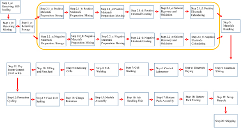
The specific process used for battery production plays a significant role in determining the resultant cost of battery manufacturing, as shown in figure 8. The production process begins with the acquisition of raw materials. Materials necessary for the production of the positive and negative electrodes, and the electrolyte, make up the highest raw material purchase costs. In this analysis, the solvent to be used for the battery electrolyte is chosen as 1,2-dimethoxyethane (DME). The price of DME is $134 l−1, which is cheaper than ethylene carbonate but costlier than propylene carbonate. Li and TiC are chosen as the anode and cathode materials for the process flow diagram. The TiC-based cathode exhibits an energy storage capacity comparable to the graphite cathode, but suffers from significantly lesser parasitic reactions. It also serves as a more reliable base for the formation-decomposition of Li2O2 than pure graphite. After initial electrode preparation, the coated electrode foils are cut into strips and dried by heating under vacuum. This is one of the critical stages of battery manufacturing as moisture must be eliminated during this process to prolong battery life. The control laboratory is then used to verify the quality of raw materials and the produced electrodes.
The next phase, assembly, involves stacking the cells, welding the current collectors and placing the cell inside an enclosed container to be filled with electrolyte and sealed. The sealed container is placed into a dry-room atmosphere, kept at a maximum dew-point temperature of −40 °C. Sealed cells are monitored in this environment as they are cycled and tested for charge retention through a full charge-discharge-recharge cycle. Defective cells are rejected and recycled, and the accepted cells are passed on to the AHU, where they are exposed to pure oxygen. The oxygen in this AHU is purified of contaminants by means of an Air Products Dehydration Membrane composed of hollow polymeric fibers, chosen here as the Prism Cactus membrane (model PC4030-D2-6A-20). The unit price of this membrane is between $4000 and $7000. Once the cells are processed with purified oxygen, they are finally assembled into battery packs. The battery packs are discharged to verify overall impedance, and then recharged to a stable level for long-term storage and shipping.
Figure 8. The modeled manufacturing process flow for the lithium–air battery consists of 20 key stages outlined here. Special attention is directed to the stages involved with the production of the cathode and the anode. These stages are outlined within the yellow bounding box in the diagram.
Download figure:
Standard image High-resolution image
4.3.4. Battery management system
The battery management system (BMS) is critical for controlling the charging and discharging of the battery and maintaining its overall safety and reliability. The BMS also handles cell balancing and thermal management of the battery pack, which is necessary to avoid reduction in performance and ensure safety against explosion of batteries due to overcharging or abuse, and is expected to predict the behavior of the battery over its lifetime [96–98]. The BMS consists of sensors, actuators and controllers which monitor and control the battery state [96]. BMS has a distributed architecture comprising of the battery control unit (BCU) and the battery measurement unit (BMU). The BCU is used to compute the battery parameters and send control order to BMU. The BMU is responsible for measuring cell votages, total voltage, current, insulation resistance and temperature [99, 100]. Power and energy prediction is required to calculate the available energy for functioning at the given point of time and maximum power that is instantaneously available if required at that time. For power and energy prediction, a good BMS should also be able to predict the degradation of battery components over time. Power and energy prediction is done by monitoring the bulk state of charge (SOC) and surface SOC [101]. The bulk SOC is calculated by integrating the measured current over time. Safety and reliability is monitored by measuring and controlling the voltage and temperature of the battery and a quantity called state of health (SOH). The SOH is a figure of merit of present condition of battery compared to its ideal conditions. The SOH quantifies the degradation of the battery over time [98, 102]. In addition to this, the BMS also calculates various model parameters like film resistance, diffusion coefficients, etc, to maintain the accuracy of the model used for prediction.
For controlling the battery efficiently, a good model for the battery is required. Various models have been used to predict the battery behavior. The most typical BMS employ equivalent circuit models, which are based on representing the battery in term of an electric circuit based on resistors and capacitors whose resistance and capacitance is fitted using experiments [103–105]. Alternatively, physics based electrochemical models have also been developed to overcome the limited prediction capability of equivalent circuit models. Physics based electrochemical models are based on the electrochemical equations describing the battery dynamics and hence are far more accurate in spite of the assumptions and approximations made [97]. The electrochemical models are one dimensional and assume the electrodes to be comprised of spherical particles whose size varies with material deposition/removal during charging/discharging and a separator between the electrodes to describe the diffusion of cations across the electrodes [106–108]. The equivalent circuit models are computationally inexpensive but have low accuracy over a wide range of electrochemical potentials and don't capture degradation effectively. The physics based models are quite accurate, but computationally quite expensive as they involve solving a set of non-linear PDEs. The complexity of the controller also depends on the complexity of the model used. Thus a computationally cheap model that captures the physics of the battery has to be developed.
One major challenge for BMS is accurate and synchronous measurement of the battery current and the voltage of the pack cells, along with data communication over a number of voltage domains and fulfillment of ASIL-C safety requirements. Voltage accuracy of 1–2 mV at the cell level and 0.1% at the pack level, current measurement with an accuracy of 0.5–1% upto 450 A and temperature accuracy of 1°C for −10 to 100 °C is required [99, 100, 109]. SOC, SOH and other battery parameters need to be predicted with an accuracy of 5%. Other challenges for the development of BMS include building an analytically tractable model for capturing the physics of the batteries, building efficient methods for determining and calculating battery state variables as bulk SOC, surface SOC and SOH in real time and designing quick offline estimation strategies for identifying the battery model parameters. A few physics-based models have been developed for Li–air batteries and however, these are still in the nascent stage and require further validation [110–112].
5. Conclusions
The most critical near-term challenges for all presented BLI chemistries concern the materials used in these batteries. New materials and mechanisms are required to address issues of dendrite formation, prevention of electrolyte breakdown, or improvement of electrode stability. Efforts will have to be expanded to consider the benefits of using blends and additives, particularly for the electrolyte. The properties of the observed discharge products have to be completely characterized to allow for a predictive analysis of battery operation. Detailed study of material properties of the batteries may also shed light on potential solutions that would not necessitate selection of a new material base. For instance, the knowledge of the mechanism of dendrite formation may allow for an ion conductor to be simultaneously used as a mechanical block against dendritic growth. We have provided a comprehensive discussion of the fundamental material challenges that face the BLI chemistries.
Finally, as new battery technologies mature, it will be important to project their potential market performance both in terms of available material supply and expected market demand. As BLI batteries are developed to practicable standards in manufacturer R&D laboratories, it is vital to study and gauge the market and probe for the most effective time and environment where the new designs can be introduced. The reliance of modern electronics and vehicular transportation on rechargeable batteries does not guarantee the acceptance of any new system, even if it is more energy-dense. Cooperation between battery manufacturers and device manufacturers will be important, as will be the creation and support of a dependable supply chain to ensure consistent and sustainable delivery raw materials of high quality.
The world is increasingly reliant on electricity for everyday tasks. From computers and cellular phones to electric cars and aircrafts, compact high-energy density batteries are a vast and growing market in need of more sustainable, cheaper solutions. As the importance of electrical energy storage grows, so do the long-term challenges related to resource availability and widespread affordability. Current batteries work very well, but further improvements are necessary as lithium is ultimately a limited resource and needs to be used as efficiently. Recent surge in the scientific endeavors in BLI technologies looks promising, and it seems likely that a number of them may be developed to a marketable stage within the next decade.
Finally, we have introduced a novel method of quantification of the hype surrounding emerging rechargeable battery technologies, based on their apparent popularity within the scientific community. The method is a quantitative approach, relying only on statistics of periodic paper publications, and not on subjective opinions. We believe that this method is applicable to a wide range of academic topics going through early stages of development, and is a more reliable marker of development than popular media, because it reflects the interest of actively working researchers rather than passive consumers. As we observe the continued development of high-energy-density rechargeable batteries, we believe we will be able to map all of the stages of the cycle more precisely, which will help forecast the timeline of development for subsequent designs.
Appendix.: Battery publications
A.1. Figures and fits
Table A1. Papers published each year on lithium–ion and beyond-lithium–ion batteries between 1996 and 2014, inclusive.
| Year | Li–air | Na–air | Li–sulf | Redox Fl | Mg–Ion | Na–ion | Li–ion |
|---|---|---|---|---|---|---|---|
| 1996 | 1 | 0 | 0 | 3 | 0 | 0 | 162 |
| 1997 | 0 | 0 | 0 | 4 | 0 | 0 | 192 |
| 1998 | 0 | 0 | 0 | 5 | 0 | 0 | 259 |
| 1999 | 0 | 0 | 0 | 1 | 1 | 0 | 365 |
| 2000 | 0 | 0 | 0 | 1 | 2 | 0 | 343 |
| 2001 | 0 | 0 | 1 | 2 | 6 | 0 | 474 |
| 2002 | 1 | 0 | 9 | 7 | 3 | 0 | 512 |
| 2003 | 1 | 0 | 9 | 4 | 2 | 0 | 657 |
| 2004 | 0 | 0 | 11 | 13 | 2 | 0 | 683 |
| 2005 | 2 | 0 | 10 | 11 | 2 | 0 | 841 |
| 2006 | 1 | 0 | 13 | 14 | 2 | 0 | 1035 |
| 2007 | 6 | 0 | 11 | 17 | 4 | 0 | 1123 |
| 2008 | 4 | 0 | 15 | 18 | 5 | 0 | 1138 |
| 2009 | 10 | 0 | 13 | 23 | 3 | 0 | 1372 |
| 2010 | 61 | 0 | 24 | 29 | 6 | 0 | 1691 |
| 2011 | 95 | 1 | 44 | 85 | 7 | 0 | 2401 |
| 2012 | 180 | 2 | 97 | 100 | 15 | 5 | 3195 |
| 2013 | 287 | 8 | 264 | 174 | 13 | 14 | 5249 |
| 2014 | 327 | 13 | 428 | 195 | 31 | 10 | 6769 |
Note: The numbers were retrieved using the web of knowledge: web of science database, with the search queries listed out below. Li–air: 'lithium–air' OR 'lithium–oxygen' OR 'lithium–o' OR 'Li–air' OR 'li–oxygen' OR 'li–o' AND 'battery'. Li–ion: 'lithium–ion' OR 'Li–ion' AND 'battery'. Li–s: 'lithium–sulphur' OR 'lithium–sulphur' OR 'lithium-s' OR 'Li–sulphur' OR 'Li–sulphur' OR 'Li-s' AND 'battery'. Mg–ion: 'magnesium-ion' OR 'mg–ion' AND 'battery'. Na–air: 'sodium–air' OR 'sodium–oxygen' OR 'sodium–o' OR 'Na–air' OR 'na–oxygen' OR 'na–o' AND 'battery'. Na–ion: 'sodium–ion' OR 'na–ion' AND 'battery'. Redox flow: 'redox flow' AND 'battery'.
Biographies

Oleg Sapunkov Mechanical Engineering Ph.D. Student at Carnegie Mellon University B.A. in Physics, Psychology from University of California, Berkeley Current focus of research: Rechargeable Metal-Air Batteries

Vikram Pande Mechanical Engineering Ph.D. Student at Carnegie Mellon University B.Tech. and M.Tech. in Mechanical Engineering from Indian Institute of Technology, Bombay Current focus of research: Rechargeable Li-Air and Lithium-ion batteries

Abhishek Khetan Doctoral Student at Institute for Combustion Technology, RWTH Aachen University M.Tech/B.Tech in Mechanical Engineering from Indian Institute of Technology, Kanpur, India Current focus of research: Rechargeable Metal-Air Batteries and Materials for SCR

Chayanit Choomwattana Energy Science, Technology, and Policy concentrated on Chemical Engineering a Master Student at Carnegie Mellon University B.E. in Chemical Engineering from Chulalongkorn University Current focus of research: Lithium Extraction

Professor Venkatasubramanian Viswanathan Assistant Professor of Mechanical Engineering at Carnegie Mellon University Ph.D. in Mechanical Engineering from Stanford University M.Tech/B.Tech in Mechanical Engineering from Indian Institute of Technology, Madras